THE DESIGN OF THE MOTIVE POWER EQUIPMENT
|
|
|
- Nathaniel Grant
- 6 years ago
- Views:
Transcription


1


2 4* -4. ^ 1^


3
4


5 THE DESIGN OF THE MOTIVE POWER EQUIPMENT FOR AN ELECTRIC STREET-CAR BY HAL EDMUND ERCANBRACK THESIS FOR THE DEGREE OF BACHELOR OF SCIENCE IN RAILWAY ELECTRICAL ENGINEERING IN THE COLLEGE OF ENGINEERING OF THE UNIVERSITY OF ILLINOIS Presented June, 1909

6


7 UNIVERSITY OF ILLINOIS June 1, i9o9 THIS IS TO CERTIFY THAT THE THESIS PREPARED UNDER MY SUPERVISION BY HAL EDIOTD IROANBRACK ENTITLED THE DESIGN OF THE MOTIVE POWER EQUIPMENT FOR AN ELEO- TRIO STREET-CAR!S APPROVED BY ME AS FULFILLING THIS PART OF THE REQUIREMENTS FOR THE DEGREE OF Baohelop of Science in Railway Electrical Engineering APPROVED: HEAD OF DEPARTMENT OF Railway Engineering

8


9 IND EX INTRODUCTION - PACxE 1 PRINCIPLE OF DESIGN " 1 DESIGN " 4 DESCRIPTION " 8 METHOD OF OPERATION " 11


10 Digitized by the Internet Archive in


11 THE DESIGU OF THE MOTIVE POVJER EQ.UIPMENT FOR AN ELECTRIC STREET-CAR Int rodu_c1; i_on. ^ In the oporaticn of city railway cars, an averaf^e of about nine-tenths of the pov/er consumption is used in their acceleration. That is, in acceleration, the energy curve rises to an excessive height immediately at the start of the car and gradually becomes lovier until it forms a straight line when the speed of the car is uniform. From a study of curves of this kind, it is seen that a cutting off of the upper parts of the curves during acceleration would result in a great saving in the current consumption and cost of plant installation and operation. In bringing the car to rest, energy is dissipated at the brake shoes and nothing is realized from this wasted energy. By designing a machine which would utilize this energy which is ordinarily v/asted in bringing the car to rest and give it forth again in accelerating the car, v/e have a means of eliminating the excessive consumidtion due to acceleration. PrinGi_ple of ne3^i n_ The main feature of this thesis, therefore, is the design of a reversible air machine, i.e., one which can be operated as a compressor in one case and which can also be changed to operate as a compressed air engine in the other case, by a system of cams and connections. This s^'-stem, of course, necessitates a reservoir for holding the com-

12


13 2 pressed air. The ordinary electrical eq-uipment will be installed on the car ^ith the exception that t7/o motors will be used instead of four as on the larger city cars at present, or if the system should bo installed on the smaller two truck cars, where two motors are ordinarily used, two motors will be used but of smaller capacity. Considering single truck cars, one electric motor will be used and one air machine; and one the double truck cars, one motor and one air machine will be placed on each truck. This thesis, hov^ever, will be confined to the large "Pay as you Enter" type of car such as are used in Chicago at present. The tractive power of electric cars used in the United States usually runs from 30 to 35 percent of the weight on the car wheels. Considering this, the first part of this design will bo to select the body and trucks of the car which will have a known weight, from which can be calculated the maximum allowable tractive power. Prom the formula L X 350 X Jlfi\ 8 - T ttd where L = length of compression stroke in feet, 250 = pounds gauge pressure used in the reservoir which is used in connection with the compression, d = diameter of compressor cylinders in inches, T = tractive power delivered to the rails, D = Divametcr of car wheels in feet, and 8 = number of cylinders in the two air machines.
14


15 3 we arrive at T = 50q_L ^ By subtracting the tractive power v/hich the chosen motors v/ill give from the total tractive pov/er necessary to move ths car under all conditions for rated speed and capacity, we obtain the tractive power which the air machines must give in accelerating the car. Having deteriainod this, by substitution in the above formula, we are able to choose the size of the cylinders, the ratio of the stroke to the diameter depending, however, on the conditions as to space on the trucks. If a reduction gearing is used, the formula will read T = ^ 500 L ji X Gr v/here G = gear ratio. D Then with the size of the cylinders knovm and ths average length for bringing the car to rest known or assumed, the size of the reservoir can be calculated which will bring the pressure up to that assumed at the beginning, 350 pounds per square inch. Prom test books, we know that when the temperature of a volume of gas remains constant, we have. the relation P V = P, V, where P and V represent the pressures and volumes of the gas. Or V - P/ V/ P where V, = volume of all the air compressor cylinders for one stroke each. Then

16


17 4 365 where 15 = the normal atmospheric pressure and 365 = the absolute pressure in the reservoir v/hen the gauge reads a pressure of 350 pounds per square inch. Then V times the numbex of strokes which the compressor pistons make Trhile the car is being brought to reat, results in the volume of the reservoir, from Trhich, its proportions can be assumed according to conditions. Of course, if the average length for bringing the car to rest is not long enough to fill the reservoir at 350 pounds pressure v/hich is sufficient to start the car for a desired distance, tho air compressors may be connected while the car is being run by the motors and a larger reservoir used. Or if there is not sufficient tractive pov;er developed by the engines, a higher gear ratio may be used when there is not roora enough to make the cylinders larger. The motors and air machines will be used together in tho acceleration of the car and when it is well under way, the motors V7ill be used alone and their size '.vill depend upon the desired maximum speed of the car. The compressors will be put into use while the car is being brought to reat and pump air into the reservoir, thus utilizing the energy otherwise dissipated at the brake shoes. Deoi_gn In starting the design according to the foregoing
18


19 5 principles, the follov;ing assumptions are made: The averae;;e weight on the '.vheols of the "Pay as you Enter" t^'-pe of cars is 30 tons;- tv7o-50 horse power motors will "oe used;- 250 pounds pressure in reservoir;- tv/o air machines - 4 cylinders each -.vill be used;- SS-inch car v/heels;- 150 feot for bringing the car to rest. Then considering 35^ of the weight on the car wheels as the tractive pov/er to be used on the car, we have, 35^ of 60,000 = 15,000 pounds allowable tractive power. Then allowing the compressed air engines to take care of half of the tractive p07;er, we have 7500 pounds tractive power for the engines and 7500 pounds tractive power for the two electric motors, the capacity of each motor being the sai.ie as on the original car. In the formula - T L d^ let T = 7500 and D = 3.75 feet. Then a A 3.75 and L d^ = Let L = 5/6 feet and. d = 49.5 d = 7 inches = diameter of cylinders.
20


21 6 Then taking 150 feet as the average distance for bringing the car to rest; 150 feet ~ 7300 inches. A 35-inGh wheel travels 53 x tt inches in one revolution. Then 33 XTT = 6S.5 or 70 revolutions in 150 feet of travel. Then?/ith a gear ratio of 1 : 1, the piston strokes for a single acting engine are the same. Considering the reservoir, V = V X ll7ith X 10" cylinders, V, = 384 cubic inches - volume of one cylinder, V = ^.,5_15» 31,8 cubic inches ~ volume of 365 the air under pressure of 350 pounds guage. Then since there are eight cylinders in the t'.vo engines, 70 X 8 X 31.8 = cubic inches or 7 cubic feet which is the volume of the air compressed with the car traveling 150 feet. This, then, equals the size of the reservoir. Due to the fact that only about 50 per cent efficiency Ccin be realized from an engine of this sort, a gear ratio of 2 : 1 may bo used with the sa:::e size of cylinders. Then the number of strokes would be 140 in bringing the car to rest and the capacity of the reservoir v/ould be doubled also. Now considering 35 miles per hour as the average maximum speed of city cars between stops, the strokes per min-
22


23 7 ute of the pistons would equal l^_jl_?30q - 35 X strokes when a 1 : 1 gear ratio is used. But with a gear ratio of 2 : Ij this speed of strokes would ho too nigh since about 300 strokes per minute is the most practical speed to operate engines of this sort. Since the size of cylinders is about as large as can be conveniently put on trucks whore four cylinders are used, a compromise may be arrived at, which will take care of this 50 per cent efficiency of the air machines by leaving the size of the reservoir as 14 cubic feet and the gear ratio as 1 : 1 without changing the size of the cylinders. This size of reservoir is better since with a small one of 7 cubic feet, aft or the first few strokes of the pistons, the pressure in the reservoir would be so reduced as to lower the power of the engines by more than half. This size of reservoir with the original size of cylinders as chosen, necessitates running the compressors for about 300 feet instead of 150 feet. This may be done while the motors are running without much more current consumption. In this manner, the pressure in the reservoir can be brought up to such a point that in bringing the car to rest in the remaining 150 feet as allowed, the final pressure will be brought up to.350 pounds. This can be done to a great degree of accuracy v/ith but little practice. Therefore, Gear ratio 1 : 1 will be used,
24
 ^^^^ 38.")

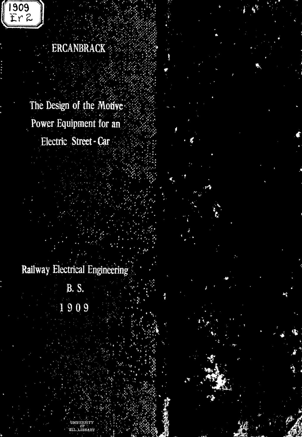
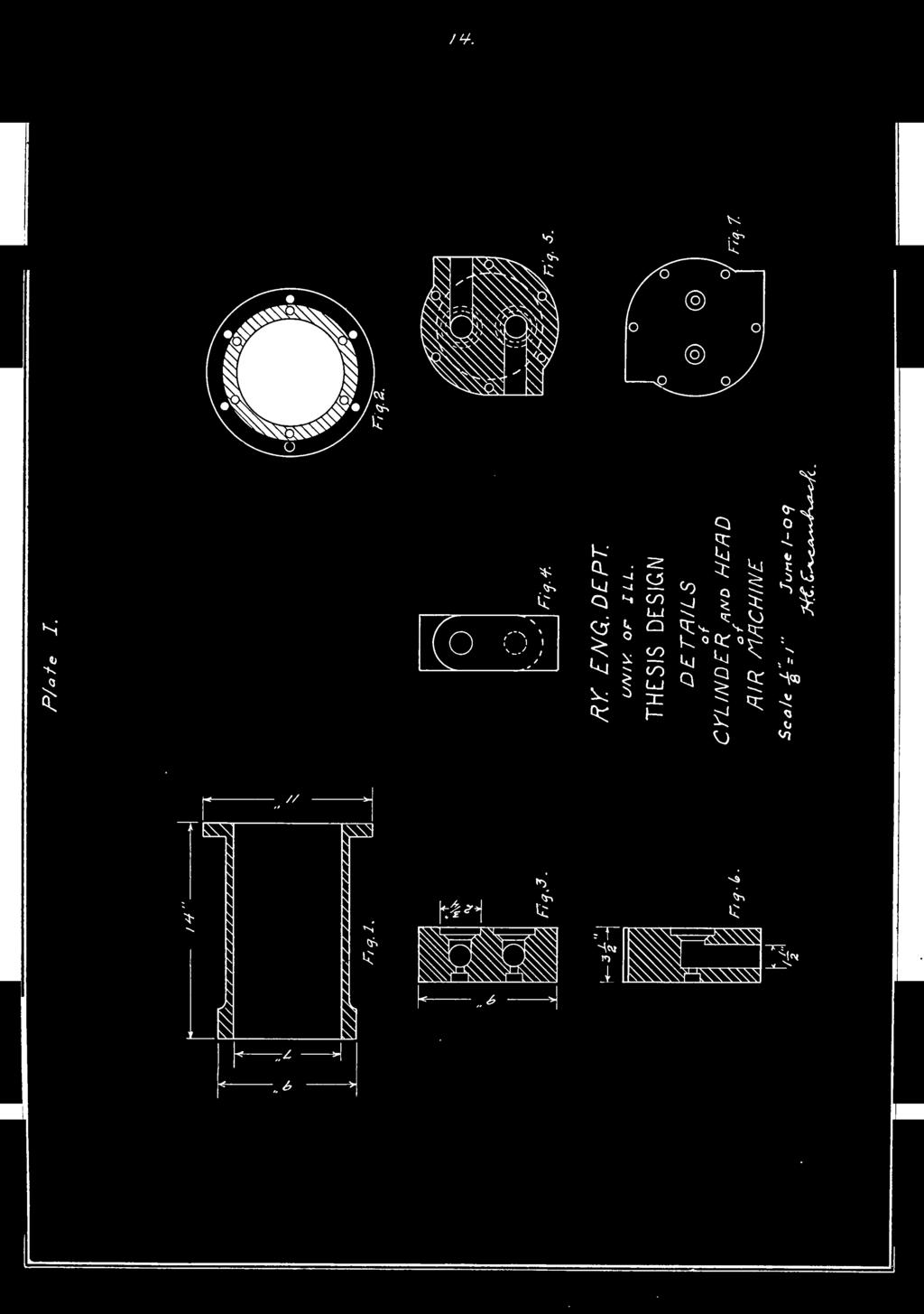
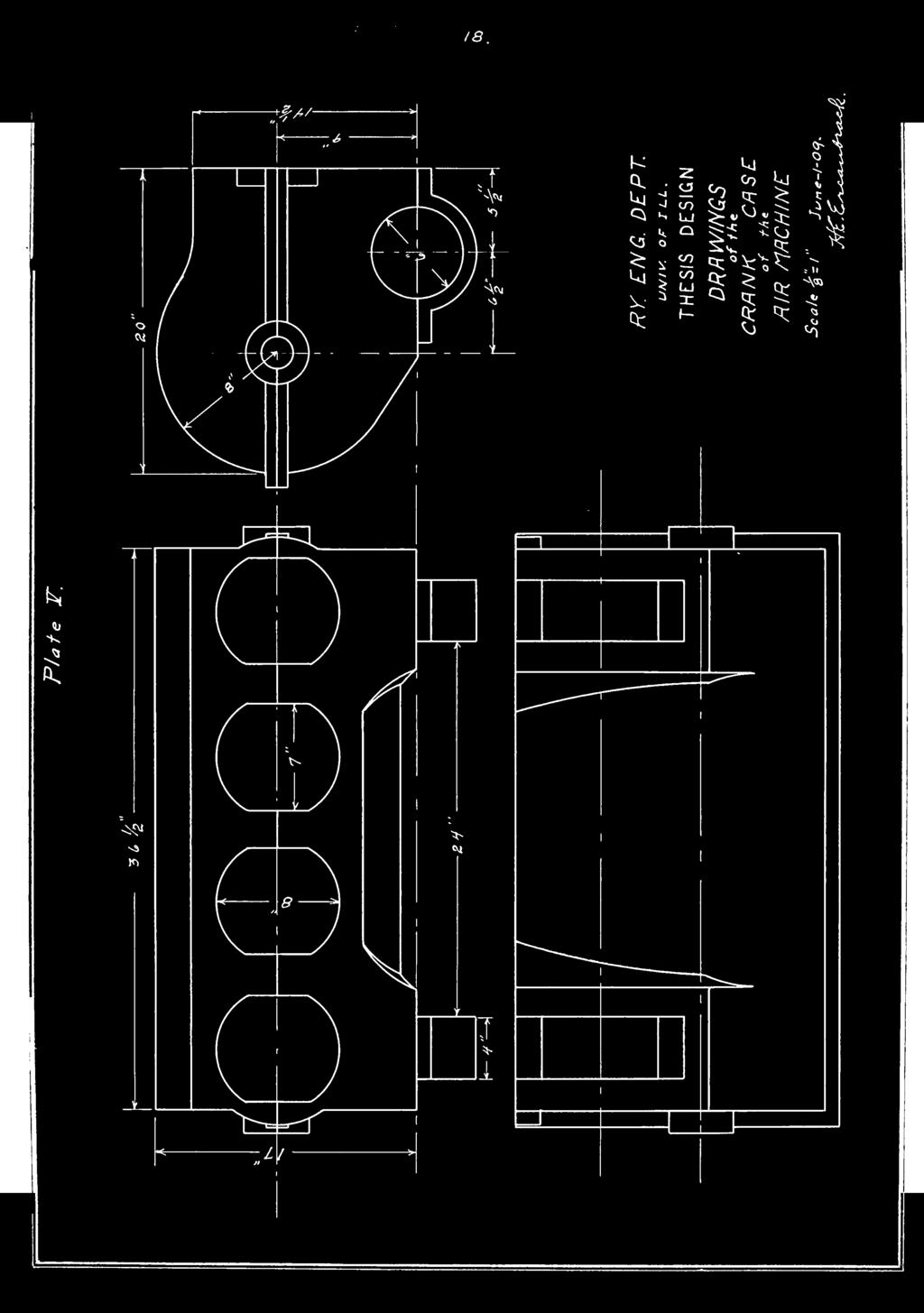
25 7" X 10" cylinders will be used, and 14 cubic feet reservoir. In calculating the valve lift, 6000 feet per minute is used as the velocity of tho air. On this assumption, L 2 RPM «iz^x 10 X 355 = cubic inches per minute through the = 57 cubic feet nor minute = velocity of air cylinders. Then ^'^ = X (area of po rt) ^^^^ 38.5 (area of cylinder) Then X ==».36 square inches. Assuming 1-1/3 inch poppet valves, from formula area of opening = circur.f erence x valve lift x.71, we have.36 = 4.71 x X x.71, X = =.108 inches or 1/8 inch lift _Deacript ion_ Plate 1 shows the cross-section view and head end view of the cylinders, Fig. 1 and 3, and also various views of the cylinder head, Fig, 3, 4, 5, 6 and 7, which contain the valve seats and air inlets and outlets. Plate 3 shows three views of the piston. Fig. 1, 3 and 3, showing tho general construction. The poppet valves

26


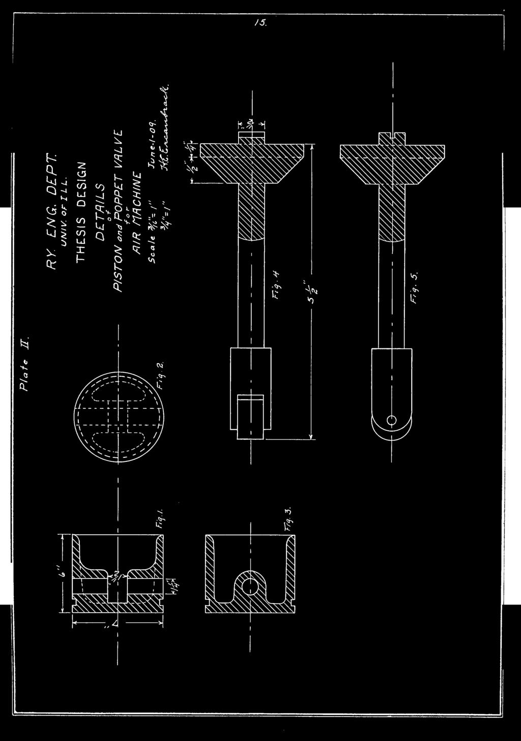
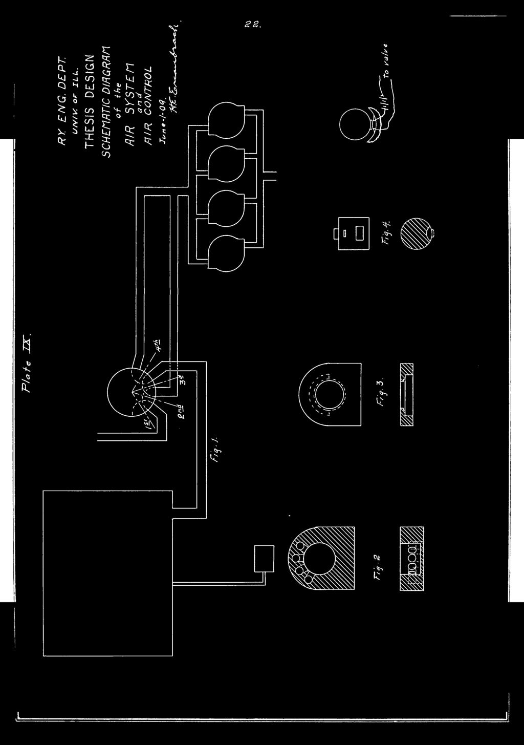
27 9 which are the t3'pe chosen are shown on this plate, Fig. 4 and 5. Plate 3 shows the crank and connecting rod construction. The figures on Plate 4 are partly dravm to scale and partly schematically. Figure 1 represents the cam rod and bevel gear arrangement. This shows the scheme used for changing the set of cans so that the machine will act as a compressor or as an engine. Figure 3 is a schematic diagram of the elect ricall3'' operated air valve which admits air from the reservoir to the cylinder at the end of the cam rod. This air valve is the standard type of valve now used in e- lectrioally operated work. The air works against the spring as shown and forces the cam rod over so that another set of cams is brought against the poppet valve sterns thus changing the action of the machine from that of a compressor to that of an engine. The spring shovm in the figure holds the rod so that normally with no air pressure in this cai:: rod cylinder, the machine works as a compressor, A 7/orm gear is used to transmit the crank action to the cam rod. This rod is a hollow tube, feather keyed to a smaller rod over 'Thich it slides in making the changes. The smaller rod receives power or motion from a set of bevel gears and the hollo?; rod carries the cams proper. Fig. 3 represents the cam on the cam rod working a- gainst the poppet vala'^e roller. This also shows the cam construction as well as the roller, Plate 5 shows various outside views of the crank case

28


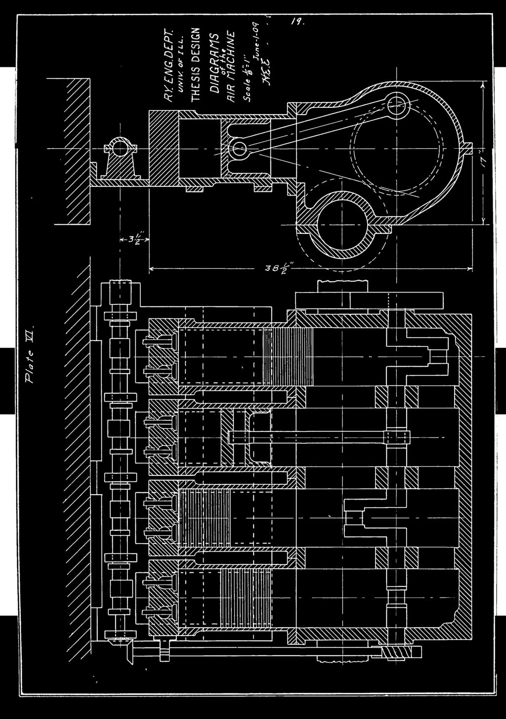
29 10 in Y/hich ohg axle supports can be seen. Plate 6 Gho77S the side elevation of one cylinder working and also a plan vier; of all cylinders and the respective positions of the pistons in the different cylinders. The cair. rod supports and the rear beam support of the r.achine are also shovm here. Plate 7 shows the front vie'.r of the car truck and the air machine in position. This also gives a good idea as to the support on the car axle and the relative size of the machine and truck, Plate 8 shov/s a top vicv^ of the niachine in place on the truck. This viev; also sho'7s the beam support to good advantage and the position of the air valve and earn rod cylinder. The electric motor is net shown but -vill be placed on the other car axle. The sarae system will be carried out in the other car truck. Plate 9 shov/3 a schematic vie\7 of the air system and the air control valve. Other views of the control are shown in figures 2, 3 and 4. Figure 2 represents the outside or bottom part of the control v/ith the air pipe connection arrangements. Figure 3 represents the top which bolts to the one shown in figure 3 and holds the movable part in place. Figure 4 shows the movable part of the control which is operated by a handle the same as all controls. The circular recess cut in the side of this part is the connecting part between the different pipes so that the air can pass from the two adjacent pipes in that position of the control. Above this recess is shown a brush contact which closes the circuit

30


31 11 to the electrically operated air valve for the car.- rod shifting operation. The two brushes 3ho\7n in figure 5 ^hich run to the air valve are fastened in the piece shovm in figure 3 and set in such a position that \7hen the control handle is in the air engine position, the circuit is closed and the cams are shifted. _M thod of_02oration_^ In the schematic diagram are shovm the various control positions. First position is the one in which the air connections to the cylinders are closed and the pistons are v;orking against the air as a cushion which forms a sort of final braking. This position of the control will not be used much since the volume of the air in the pipes \7ill allo\7 for too much elasticity. The car will also be equipped with the regular air brake system for the final braking of the car. Second position is the neutral position in v.'hich the cylinders are open to the air and no work is being done on or b]"" the air. This is the position in which the controller v;ill normally bo set for running between stops after the car is brought up to speed and before it is being brought to rest. Third position is the one in which the machine is working as an air compressor with the car;, rod in its normal position. Fourth position is tho one in which the nachin'= is working as a compressed air engine with the air supply com-

32


33 ing from the redervoir and. the contact made to close the circuit to the air valve for shifting the cam rod. to the other position. Sup-pose the c.^r is at rest and the reservoir full of air at 350 pounds guage pressure. To start the car, the brakes are first released as usual. Then the air controller is switched froin the 3d position to the 4th position which may or may not start the car in motion according to existing circumstances. Ilext, v;hether the car is in motion or not, the electric controller is turned and the motors "brought into use. After the speed of the car has become uniform, the air cont roller is switched back to the 3d position and air is pumped into the reservoir until the pressure reaches a point at which it is kno^;m that the bringing of the car to rest in the stated 150 feet T;ill bring it up to 350 pounds,?jhen the pressure has reached this critical point as v;e vrill call it, the air controller is switched back to the 2d or neutral position and left there until within 150 feet froi.: the next stop. The electric controller is shut off if not a.lready in that position and the air controller is again switched over to the 3d position and left there until the final stop is made and then put back to neutral. The final stop is made by the air brake. It is best to watch the reservoir guage during acceleration and always manage to keep it about 50 pounds so as to allow for sudden braking as the air brake system suppl3'- is taken from this reservoir.
34 I i. r i

35 13 A little practice in the operation of this car will enable one to do it v;ith ease notv/ithstanding the extra control handle as compared with the ordinarv eloctric car.
36

37


38

39 /5.

40


41 /i>. 2 CJJ -J 00 Ci s UJ Q Q 02 CO U X 1- Q <o Cir J
42

43
44 i

45
46

47

48

49 ' 2 0. o o JO o 1 ^nnnm' I UUUUI

50

")
51 SI. to Or Vo 5^ 6 ( ) ( ) O ( )
52 I I

53


54
55


56
VAN GUNDY & FICK. ELgcirical Lngmeermg. Raisers' ^l:t.s-s ilegd&lw: D. p. DNIV.OV ' OIL 1*;. ;,,; I; 'i. / v- ''UK ','.!'
 I ' i ' I; 'i VAN GUNDY & FICK ','.!' if / v- ''UK Raisers' ^l:t.s-s ilegd&lw: ELgcirical Lngmeermg P C D. p. 1912 1*;. ;,,; DNIV.OV - I CAJJtiTO MS a V.UUf./UVV". "I*. ' OIL THE UNIVERSITY OF ILLINOIS
Air Brakes From Real Trains
 Air Brakes From Real Trains Real Trains has been producing air brake systems for our 1 1/2 scale trucks for more than seventeen years. In this time over 100 pairs of trucks equipped with air brakes have
Al- Ameen Engg. College. Fluid Machines. Prepared by: AREEF A AP/ ME AL AMEEN ENGINEERING COLLEGE Shoranur.
 Fluid Machines Prepared by: AREEF A AP/ ME AL AMEEN ENGINEERING COLLEGE Shoranur Classification of hydraulic machines HYDROULIC MACHINES (I) Hydraulic Turbines A hydraulic machine which converts hydraulic
Common Terms Selecting a Turbocharger Compressor... 4
 TURBOCHARGERS Common Terms... 2 Adiabatic Efficiency... 2 Pressure Ratio... 2 Density Ratio... 2 Turbine... 2 A/R Ratio... 2 Charge-Air-Cooler... 2 Boost... 3 Waste Gate... 3 Turbo Lag... 3 Boost Threshold...
Applied Fluid Mechanics
 Applied Fluid Mechanics 1. The Nature of Fluid and the Study of Fluid Mechanics 2. Viscosity of Fluid 3. Pressure Measurement 4. Forces Due to Static Fluid 5. Buoyancy and Stability 6. Flow of Fluid and
LogSplitterPlans.Com
 Hydraulic Pump Basics LogSplitterPlans.Com Hydraulic Pump Purpose : Provide the Flow needed to transmit power from a prime mover to a hydraulic actuator. Hydraulic Pump Basics Types of Hydraulic Pumps
CHAP: MACHINES Q: 1. Q: 1(Numerical) Answer Total length of crowbar =120 cm Load arm =20 cm Effort arm = =100 cm Q: 2
 Answer Total length of crowbar =120 cm Load arm =20 cm Effort arm = =100 cm Q: 2") CHAP: MACHINES Ex: 3A Q: 1 A machine is a device by which we can either overcome a large resistive force at some point by applying a small force at a convenient point and in a desired direction or by which
CHAP: MACHINES Ex: 3A Q: 1 A machine is a device by which we can either overcome a large resistive force at some point by applying a small force at a convenient point and in a desired direction or by which
Cast Steel Tilting Disc Check Valve
 ast Steel Tilting heck Valve Typical Tilting heck Valve Tilting heck Valves consist of a cylindrical housing, with a pivoted circular disc. The pivots are located just above the center of the disc, and
ECH 4224L Unit Operations Lab I Fluid Flow FLUID FLOW. Introduction. General Description
 FLUID FLOW Introduction Fluid flow is an important part of many processes, including transporting materials from one point to another, mixing of materials, and chemical reactions. In this experiment, you
Driver Driven. InputSpeed. Gears
 Gears Gears are toothed wheels designed to transmit rotary motion and power from one part of a mechanism to another. They are fitted to shafts with special devices called keys (or splines) that ensure
12/25/2015. Chapter 20. Cams. Mohammad Suliman Abuhiba, Ph.D., PE
 Chapter 20 Cams 1 2 Introduction A cam: a rotating machine element which gives reciprocating or oscillating motion to another element (follower) Cam & follower have a line constitute a higher pair. of
Technical Math 2 Lab 3: Garage Door Spring 2018
 Name: Name: Name: Name: As you may have determined the problem is a broken spring (clearly shown on the left in the picture below) which needs to be replaced. I. Garage Door Basics: Common residential
& 9. Š. Aerary 4. Morazzzzzok. May 19, : 1,538,208. INVENTORS INTERNAL COMBUSTION MOTOR. atz Aazzzz c1. A1arclaezzf H. A. NORDWICK E. A.
 May 19, 1925. :. H. A. NORDWICK E. A. INTERNAL COMBUSTION MOTOR Filed Oct, l9, 1923 2. Sheets-Sheet. & 9. Š W S A. SSS S S R Sr. SS SS INVENTORS Aerary 4. Morazzzzzok atz Aazzzz c1. A1arclaezzf. ar a ATTORNEY
CHAPTER 6 GEARS CHAPTER LEARNING OBJECTIVES
 CHAPTER 6 GEARS CHAPTER LEARNING OBJECTIVES Upon completion of this chapter, you should be able to do the following: Compare the types of gears and their advantages. Did you ever take a clock apart to
TAN OEM' TRACTORS. ~GRtCULTURE LIBRARY. Extension Service in Agriculture and Home Economics UNIVERSITY OF ILLINOIS COLLEGE OF AGRICULTURE
 CIRCULATING COpy UNIVERSITY OF IlUNOIS IGRICULlURE LIBRARY ~GRtCULTURE LIBRARY TAN OEM' TRACTORS Wendell Bowers and B. J. Butler I r 7 ' _"..-1 Circular 829 UNIVERSITY OF ILLINOIS COLLEGE OF AGRICULTURE
INDIAN INSTITUTE OF TECHNOLOGY KHARAGPUR NPTEL ONLINE CERTIFICATION COURSE. On Industrial Automation and Control
 INDIAN INSTITUTE OF TECHNOLOGY KHARAGPUR NPTEL ONLINE CERTIFICATION COURSE On Industrial Automation and Control By Prof. S. Mukhopadhyay Department of Electrical Engineering IIT Kharagpur Topic Lecture
May 8, ,668,927
 May 8, 1928. J. STUMPF NONCONDENSING STEAM ENGINE Filed Nov. 0, 920 4. Sheets-Sheet A y Ál /Zevorrey. May 8, 1928. J. STUMPF NONCONDENSING STEAM ENGINE Filed Nov. O, 1920 4 Sheets-Sheet 2 D/ May 8, 1928.
Feb. 23, F.. rayfield 1,846,656 SINGLE STAGE COMPRESSOR. Fied Nov. 15, Sheets-Sheet. l. -1. s s. AederacA /ARa%e?ad. 27 (6.
 Feb. 23, 1932. F.. rayfield 1,846,656 Fied Nov. 15, 1929 3. Sheets-Sheet. l. -1. s s AederacA /ARa%e?ad 27 (6.44% as near-sell -ress Feb. 23, 1932. F. J. RAYFIELD 1846,656 Filed Nov. 15, 1929 5. Sheets-Sheet
Introduction: Electromagnetism:
 This model of both an AC and DC electric motor is easy to assemble and disassemble. The model can also be used to demonstrate both permanent and electromagnetic motors. Everything comes packed in its own
Roehrig Engineering, Inc.
 Roehrig Engineering, Inc. Home Contact Us Roehrig News New Products Products Software Downloads Technical Info Forums What Is a Shock Dynamometer? by Paul Haney, Sept. 9, 2004 Racers are beginning to realize
[P F/A] CHAPTER ,' II ' Hydraulic Actuators. cylinders. what cylinders consist of.
![[P F/A] CHAPTER ,' II ' Hydraulic Actuators. cylinders. what cylinders consist of.](/thumbs/82/85096254.jpg "[P F/A] CHAPTER ,' II ' Hydraulic Actuators. cylinders. what cylinders consist of.") CHAPTER 6 Hydraulic Actuators Hydraulic actuators convert hydraulic working energy into mechanical working energy. They are the " intswhere all visible activity takes place and one of ttlls first things
CHAPTER 6 Hydraulic Actuators Hydraulic actuators convert hydraulic working energy into mechanical working energy. They are the " intswhere all visible activity takes place and one of ttlls first things
Moments. It doesn t fall because of the presence of a counter balance weight on the right-hand side. The boom is therefore balanced.
 Moments The crane in the image below looks unstable, as though it should topple over. There appears to be too much of the boom on the left-hand side of the tower. It doesn t fall because of the presence
SHREE RAMCHANDRA EDUCATION SOCIETY S LONIKAND, PUNE DEPARTMENT OF MECHANICAL ENGINEERING LAB MANUAL. Applied Thermodynamics (ATD) Semester-IV
 Semester-IV") SHREE RAMCHANDRA EDUCATION SOCIETY S SHREE RAMCHANDRA COLLEGE OF ENGINEERING, LONIKAND, PUNE 412 216 DEPARTMENT OF MECHANICAL ENGINEERING LAB MANUAL Applied Thermodynamics (ATD) Semester-IV Prepared by
SHREE RAMCHANDRA EDUCATION SOCIETY S SHREE RAMCHANDRA COLLEGE OF ENGINEERING, LONIKAND, PUNE 412 216 DEPARTMENT OF MECHANICAL ENGINEERING LAB MANUAL Applied Thermodynamics (ATD) Semester-IV Prepared by
SIDEWINDER COURSE PREREQUISITE MANUAL
 SIDEWINDER COURSE PREREQUISITE MANUAL The S&S engine class is designed for the seasoned tech or shop owner. A certain level of knowledge and understanding is required for your success. We will be covering
2,042,301. VALVE SEAT FOR AIR BLAST WALVES Filled May 3, Sheets-Sheet. By??????r /7
 May 26, 1936. G. FOX VALVE SEAT FOR AIR BLAST WALVES Filled May 3, 1934 2 Sheets-Sheet 11 -W + By??????r /7 May 26, 1936. G. FOX WALWE SEAT FOR AIR BLAST WALWES Filed May 3, 1934 %22&zzzzzzzzº2zzzzzzzzzzzzzzzzzzzzzzzzzzzzzzzzzzzzzzzzzzzzzzzzzzzzzzzzz
SAE Mini BAJA: Suspension and Steering
 SAE Mini BAJA: Suspension and Steering By Zane Cross, Kyle Egan, Nick Garry, Trevor Hochhaus Team 11 Progress Report Submitted towards partial fulfillment of the requirements for Mechanical Engineering
B.TECH III Year I Semester (R09) Regular & Supplementary Examinations November 2012 DYNAMICS OF MACHINERY
 Regular & Supplementary Examinations November 2012 DYNAMICS OF MACHINERY") 1 B.TECH III Year I Semester (R09) Regular & Supplementary Examinations November 2012 DYNAMICS OF MACHINERY (Mechanical Engineering) Time: 3 hours Max. Marks: 70 Answer any FIVE questions All questions
1 B.TECH III Year I Semester (R09) Regular & Supplementary Examinations November 2012 DYNAMICS OF MACHINERY (Mechanical Engineering) Time: 3 hours Max. Marks: 70 Answer any FIVE questions All questions
MOREHOUSE INSTRUMENT COMPANY, INC. 60,000 LBS CAPACITY AIRCRAFT PART NUMBER SCALE S FORCE CALIBRATION PRESS PART NO.
 INDEX 1. GENERAL SPECIFICATION AND DRAWING 804000-03... 2 2. ASSEMBLY INSTRUCTIONS... 5 3. OPERATING INSTRUCTIONS... 6 4. MAINTENANCE INSTRUCTIONS... 7 5. CERTIFICATE OF CAPACITY LOAD TEST AND OVERLOAD...
Air Cylinders Drive System Full Stroke Time & Stroke End Velocity. How to Read the Graph
 1-1 Best Pneumatics Air Cylinders Drive System Full Time & End Velocity How to Read the Graph This graph shows the full stroke time and stroke end velocity when a cylinder drive system is composed of the
Carburetor Instructions
 Carburetor Instructions for HUDSON SUPER SIX ESSEX SIX CYLINDER Hudson Motor Car Co. DETROIT, U.S.A. Carburetor The carburetor is a device for metering correct amounts of fuel and air for the various
United States Patent (19)
") United States Patent (19) Ogasawara et al. (54) 75 RDING LAWN MOWER Inventors: Hiroyuki Ogasawara; Nobuyuki Yamashita; Akira Minoura, all of Osaka, Japan Assignee: Kubota Corporation, Osaka, Japan Appl.
United States Patent (19) Ogasawara et al. (54) 75 RDING LAWN MOWER Inventors: Hiroyuki Ogasawara; Nobuyuki Yamashita; Akira Minoura, all of Osaka, Japan Assignee: Kubota Corporation, Osaka, Japan Appl.
Air Cylinders Drive System Full Stroke Time & Stroke End Velocity. How to Read the Graph
 1 Best Pneumatics Air Cylinders Drive System Full Time & End Velocity How to Read the Graph This graph shows the full stroke time and stroke end velocity when a cylinder drive system is composed of the
158 PURDUE ENGINEERING EXTENSION DEPARTMENT
 158 PURDUE ENGINEERING EXTENSION DEPARTMENT repaired. With regular maintenance and a small amount of stone added each year, these roads have held up much better than we anticipated. The cost of this type
UNIT IV INTERNAL COMBUSTION ENGINES
 UNIT IV INTERNAL COMBUSTION ENGINES Objectives After the completion of this chapter, Students 1. To know the different parts of IC engines and their functions. 2. To understand the working principle of
THE AUXILIARY EQUIPMENT OF THE CHICAGO, MILWAUKEE AND ST. PAUL LOCOMOTIVES
 952 GENERAL ELECTRIC REVIEW THE AUXILIARY EQUIPMENT OF THE CHICAGO, MILWAUKEE AND ST. PAUL LOCOMOTIVES By L. W. WEBB. RAILWAY EQUIPMENT DEPARTMENT, GENERAL ELECTRIC COMPANY The auxiliary equipment of locomotives
NOTICE. The above identified patent application is available for licensing. Requests for information should be addressed to:
 Serial No.. Filing Date July Inventor Richard Bonin NOTICE The above identified patent application is available for licensing. Requests for information should be addressed to: OFFICE OF NAVAL RESEARCH
SD Bendix E-12 & E-15 Dual Brake Valve DESCRIPTION
 SD-03-6 Bendix E- & E-15 Dual Brake Valve TREADLE UPPER BODY ASSEMBLY PRIMARY DELIVERY ( ) 1 SECONDARY DELIVERY ( ) LOWER BODY ASSEMBLY MOUNTING PLATE PRIMARY SUPPLY ( SUP-1) PRIMARY SUPPLY ( SUP-) PRIMARY
Development of High Power Column-Type Electric Power Steering System
 TECHNICAL REPORT Development of High Power Column-Type Electric Power Steering System Y. NAGAHASHI A. KAWAKUBO T. TSUJIMOTO K. KAGEI J. HASEGAWA S. KAKUTANI Recently, demands have increased for column-type
Hours / 100 Marks Seat No.
 17412 16117 3 Hours / 100 Seat No. Instructions (1) All Questions are Compulsory. (2) Answer each next main Question on a new page. (3) Illustrate your answers with neat sketches wherever necessary. (4)
EFFICIENCY OF A FAIRBANKS - MORSE HORIZONTAL GAS ENGINE A. S. BERGBOM R. J. HOFFMAN ARMOUR INSTITUTE OF TECHNOLOGY
 EFFICIENCY OF A FAIRBANKS - MORSE HORIZONTAL GAS ENGINE A. S. BERGBOM R. J. HOFFMAN ARMOUR INSTITUTE OF TECHNOLOGY 1910 Iiiiiaoj!& Instittise of Technology UNIVERSITY LIBRARIES AT 172 Bergbom, A. S. Effect
Principles of Electrical Engineering
 D.C GENERATORS Principle of operation of D.C machines, types of D.C Generators, e.m.f equation of D.C Generator, O.C.C of a D.C Shunt Generator, Load characteristics of D.C.Generators GENERATOR PRINCIPLE:
FUNDAMENTAL OF AUTOMOBILE SYSTEMS
 Prof. Kunalsinh Mechanical Engineering Dept. FUNDAMENTAL OF AUTOMOBILE SYSTEMS Prof. Kunalsinh kathia [MECHANICAL DEPT.] UNIT-2 [ENGINES] PART-1 Prof. Kunalsinh kathia [MECHANICAL DEPT.] Internal combustion
CONTENT. 1. Syllabus 2. Introduction 3. Shaft 4. Coupling. Rigid coupling. Flange coupling. Sleeve (or) muff coupling Split muff coupling
 muff coupling Split muff coupling") UNIT II 1. Syllabus 2. Introduction 3. Shaft 4. Coupling Rigid coupling CONTENT Flange coupling Protected flange coupling Unprotected flange coupling Marine type flange coupling Sleeve (or) muff coupling
UNIT II 1. Syllabus 2. Introduction 3. Shaft 4. Coupling Rigid coupling CONTENT Flange coupling Protected flange coupling Unprotected flange coupling Marine type flange coupling Sleeve (or) muff coupling
Syslog Technologies Innovative Thoughts
 HYDRO-PNEUMATIC VICE WITH PRESSURE BOOSTER SYNOPSIS This project deals with the design and fabrication of the hydro pneumatic vice with an air-to-hydraulic pressure booster, the hydro pneumatic vice is
Design and Modeling of Fluid Power Systems ME 597/ABE 591
 Systems ME 597/ABE 591 Dr. Monika Ivantysynova MAHA Professor Flud Power Systems MAHA Fluid Power Research Center Purdue University Systems Dr. Monika Ivantysynova, Maha Professor Fluid Power Systems Mivantys@purdue.edu
ME 6503 DESIGN OF MACHINE ELEMENTS Mechanical Engineering Fifth Semester UNIT - 4 Part A
 ME 6503 DESIGN OF MACHINE ELEMENTS Mechanical Engineering Fifth Semester UNIT - 4 Part A 1. State any two functions of springs. (N/D 16) i) To provide cushioning effect or reduce the effect of shock or
Section Va: Valve Actuators
 Valve and Actuator Manual 977 Actuator Basics and Sizing Information Section Engineering Data Book Va Issue Date 0592 Section Va: Valve Actuators Pneumatic Actuators Page 3 Electric Actuators 5 Maximum
(12) Patent Application Publication (10) Pub. No.: US 2016/ A1
 Patent Application Publication (10) Pub. No.: US 2016/ A1") US 2016O230738A1 (19) United States (12) Patent Application Publication (10) Pub. No.: US 2016/0230738A1 Koehler (43) Pub. Date: Aug. 11, 2016 (54) ENGINE STARTER ATTACHMENT FOR (52) U.S. Cl. BATTERY OPERATED
US 2016O230738A1 (19) United States (12) Patent Application Publication (10) Pub. No.: US 2016/0230738A1 Koehler (43) Pub. Date: Aug. 11, 2016 (54) ENGINE STARTER ATTACHMENT FOR (52) U.S. Cl. BATTERY OPERATED
ME6401 KINEMATICS OF MACHINERY UNIT- I (Basics of Mechanism)
") ME6401 KINEMATICS OF MACHINERY UNIT- I (Basics of Mechanism) 1) Define resistant body. 2) Define Link or Element 3) Differentiate Machine and Structure 4) Define Kinematic Pair. 5) Define Kinematic Chain.
ME6401 KINEMATICS OF MACHINERY UNIT- I (Basics of Mechanism) 1) Define resistant body. 2) Define Link or Element 3) Differentiate Machine and Structure 4) Define Kinematic Pair. 5) Define Kinematic Chain.
Flow direction is reversed by tilting the swash plate to the opposite side of the neutral or zero displacement position.
 General Description Axial piston variable displacement pumps, Series 20, are of swash plates construction with variable flow capability suitable for hydrostatic transmission with closed loop circuit. The
DHANALAKSHMI COLLEGE OF ENGINEERING
 DHANALAKSHMI COLLEGE OF ENGINEERING (Dr.VPR Nagar, Manimangalam, Tambaram) Chennai - 601 301 DEPARTMENT OF MECHANICAL ENGINEERING III YEAR MECHANICAL - VI SEMESTER ME 6601 DESIGN OF TRANSMISSION SYSTEMS
470 Series Piston Actuators
 January 000 Bulletin 61.:470 470 Series Piston Actuators The 470 Series pneumatic piston actuators (figure 1) are used in either throttling or on-off applications with control valves having 90.5 mm (3-9/16
BULLETIN 507. Mechanical Forging Presses
 BULLETIN 507 Mechanical Forging Presses...-. ~ " The Erie Foundry Company designs and manufactu res quality machine tools that are used around the world. Erie presses have been built to stamp, cut, blank,
Pump ED 101. Variable, Fixed Speed Control - - Float Switch Activation. Introduction
 Pump ED 11 Variable, Fixed Speed Control - - Float Switch Activation Joe Evans, Ph.D http://www.pumped11.com Introduction It has been said that there is more than one way to skin a cat. In fact, there
LOCOMOTIVE ENGINEER TRAINING HANDBOOK
 LOCOMOTIVE ENGINEER TRAINING HANDBOOK February, 2006 Locomotive Control Stand Orientation An important part of your Locomotive Engineer training will be operating locomotive simulators, and your first
Comparative Study Of Four Stroke Diesel And Petrol Engine.
 Comparative Study Of Four Stroke Diesel And Petrol Engine. Aim: To study the construction and working of 4- stroke petrol / diesel engine. Theory: A machine or device which derives heat from the combustion
PATENT: ARTICULATED RHOMBIC PRISM PISTON FOR THERMAL MACHINES Filed in Italy on 18/11/2008 N TO 2008 A Inventor: Vittorio Scialla -
 PATENT: ARTICULATED RHOMBIC PRISM PISTON FOR THERMAL MACHINES Filed in Italy on 18/11/2008 N TO 2008 A 000847 Inventor: Vittorio Scialla - Nationality: italian - Resident: Via Cibrario 114, Torino (TO),
St.MARTIN S ENGINEERING COLLEGE Dhulapally, Secunderabad
 St.MARTIN S ENGINEERING COLLEGE Dhulapally, Secunderabad-500 014 Subject: Kinematics of Machines Class : MECH-II Group A (Short Answer Questions) UNIT-I 1 Define link, kinematic pair. 2 Define mechanism
SAE Baja - Drivetrain
 SAE Baja - Drivetrain By Ricardo Inzunza, Brandon Janca, Ryan Worden Team 11 Engineering Analysis Document Submitted towards partial fulfillment of the requirements for Mechanical Engineering Design I
ME6601 DESIGN OF TRANSMISSION SYSTEMS
 SYED AMMAL ENGINEERING COLLEGE (Approved by the AICTE, New Delhi, Govt. of Tamilnadu and Affiliated to Anna University, Chennai) Established in 1998 - An ISO 9001:2008 Certified Institution Dr. E.M.Abdullah
BASIC HYDRAULICS PRINCIPLES OF HYDRAULIC PRESSURE AND FLOW LEARNING ACTIVITY PACKET BB831-XA03XEN
 BASIC HYDRAULICS LEARNING ACTIVITY PACKET PRINCIPLES OF HYDRAULIC PRESSURE AND FLOW TM BB831-XA03XEN LEARNING ACTIVITY PACKET 3 PRINCIPLES OF HYDRAULIC PRESSURE AND FLOW INTRODUCTION Previous LAPs discussed
MECHANISMS. AUTHORS: Santiago Camblor y Pablo Rivas INDEX
 MECHANISMS AUTHORS: Santiago Camblor y Pablo Rivas INDEX 1 INTRODUCTION 2 LEVER 3 PULLEYS 4 BELT AND PULLEY SYSTEM 5 GEARS 6 GEARS WITH CHAIN 7 WORM GEAR 8 RACK AND PINION 9 SCREW AND NUT 10 CAM 11 ECCENTRIC
M'0 4,- UNIVERSITY OF ILLINOIS LIBRARY my. Volume. Book. Class. M rlo-20m A: ^
 M'0 '4 4,- UNIVERSITY OF ILLINOIS LIBRARY my Class Book Volume M rlo-20m 4 4 A: ^ , - ' > + 4 1- ^ -f- # f -I f f f t t f i 4- -C -i. -f 4 f 4 -ff-» f i f -f -f + ^ *^ f > f ^ 4 4^ f 4^ ^- 4- f^ 4 + 4
BRAKE SYSTEM DESIGN AND THEORY
 RAKE SYSTEM DESIGN AND THEORY Aircraft brake systems perform multiple functions. They must be able to hold the aircraft back at full static engine run-up, provide adequate control during ground taxi operations,
Technical Guide No. 7. Dimensioning of a Drive system
 Technical Guide No. 7 Dimensioning of a Drive system 2 Technical Guide No.7 - Dimensioning of a Drive system Contents 1. Introduction... 5 2. Drive system... 6 3. General description of a dimensioning
INFORMATION. covering use of Ammeter and Voltmeter ON and 1915 Model Six-54 Electrical System
 INFORMATION covering use of Ammeter and Voltmeter ON- 1914 and 1915 Model Six-54 Electrical System Hudson Motor Car Company Detroit, Michigan, IX S. A USE OF AMMETER ON 1914 AND 1915 MODEL SIX-54 With
CONCEPTUAL DESIGN OF A NEW TYPE OF ENGINE FOR VARIOUS APPLICATIONS WITH EXPECTED 10% HIGHER OVERALL EFFICIENCY
 International Journal of Mechanical and Production Engineering Research and Development (IJMPERD ) Vol.1, Issue 2 Dec 2011 58-65 TJPRC Pvt. Ltd., CONCEPTUAL DESIGN OF A NEW TYPE OF ENGINE FOR VARIOUS APPLICATIONS
UNIT -I. Ans: They are specified by the no. of strands & the no. of wires in each strand.
 VETRI VINAYAHA COLLEGE OF ENGINEERING AND TECHNOLOGY, THOTTIAM, NAMAKKAL-621215. DEPARTMENT OF MECHANICAL ENGINEERING SIXTH SEMESTER / III YEAR ME6601 DESIGN OF TRANSMISSION SYSTEM (Regulation-2013) UNIT
Code No: R Set No. 1
 Code No: R05222106 Set No. 1 II B.Tech II Semester Supplimentary Examinations, Aug/Sep 2007 MECHANISMS AND MECHANICAL DESIGN (Aeronautical Engineering) Time: 3 hours Max Marks: 80 Answer any FIVE Questions
A PORTABLE HEEL BOOM LOADER. A Thesis. Harley E. Horn. Oregon State College. Presented to the Faculty. School of Forestry. Bachelor of Science.
 A PORTABLE HEEL BOOM LOADER by Harley E. Horn A Thesis Presented to the Faculty of the School of Forestry Oregon State College In Partial Fulfilinient of the Requirements for the Degree Bachelor of Science
Test Which component has the highest Energy Density? A. Accumulator. B. Battery. C. Capacitor. D. Spring.
 Test 1 1. Which statement is True? A. Pneumatic systems are more suitable than hydraulic systems to drive powerful machines. B. Mechanical systems transfer energy for longer distances than hydraulic systems.
SD Bendix BP-R1 Bobtail Proportioning Relay Valve DESCRIPTION
 SD-03-1067 Bendix BP-R1 Bobtail Proportioning Relay Valve CONTROL SERVICE SERVICE CONTROL SUPPLY DELIVERY SUPPLY DESCRIPTION The BP-R1 bobtail proportioning relay valve is a combination of two individual
Infinitely Variable Capacity Control
 Purdue University Purdue e-pubs International Compressor Engineering Conference School of Mechanical Engineering 1972 Infinitely Variable Capacity Control K. H. White Ingersoll-Rand Company Follow this
An Analysis of Electric Inertia Simulation Method On The Test Platform of Electric Bicycle Brake Force Zhaoxu Yu 1,a, Hongbin Yu 2,b
 Advanced Materials Research Submitted: 2014-05-28 ISSN: 1662-8985, Vols. 989-994, pp 3335-3339 Accepted: 2014-05-30 doi:10.4028/www.scientific.net/amr.989-994.3335 Online: 2014-07-16 2014 Trans Tech Publications,
PREVIEW COPY. Basic Hydraulics. Table of Contents. Principles of Hydraulics...3. Lesson Four Reservoirs and Accumulators...49
 Basic Hydraulics Table of Contents Lesson One Lesson Two Lesson Three Principles of Hydraulics...3 Hydraulic Fluids...17 Strainers and Filters...33 Lesson Four Reservoirs and Accumulators...49 Lesson Five
The University of Melbourne Engineering Mechanics
 The University of Melbourne 436-291 Engineering Mechanics Tutorial Twelve General Plane Motion, Work and Energy Part A (Introductory) 1. (Problem 6/78 from Meriam and Kraige - Dynamics) Above the earth
DESIGN AND DEVELOPMENT OF TREADMILL TO GENERATE ELECTRICITY BY USING MECHANICAL ENERGY
 DESIGN AND DEVELOPMENT OF TREADMILL TO GENERATE ELECTRICITY BY USING MECHANICAL ENERGY AMIT GAIKWAD 1, AJAY JADHAV 2, PRASAD DHAGE 3, MR. SOURABH BORCHATE 4 1,2,3B.E. Student, Dr.DYPIEMR, Akurdi, Pune,
Investigating the impact of track gradients on traction energy efficiency in freight transportation by railway
 Energy and Sustainability III 461 Investigating the impact of track gradients on traction energy efficiency in freight transportation by railway G. Bureika & G. Vaičiūnas Department of Railway Transport,
Seals Stretch Running Friction Friction Break-Out Friction. Build With The Best!
 squeeze, min. = 0.0035 with adverse tolerance build-up. If the O-ring is made in a compound that will shrink in the fluid, the minimum possible squeeze under adverse conditions then must be at least.076
16.682: Technology in Transportation - Pset #2 Issued: Wednesday, February 16th, 2011 Due: Thursday, February 24th, 2011
 16.682: Technology in Transportation - set #2 Issued: Wednesday, February 16th, 2011 Due: Thursday, February 24th, 2011 Topics Covered: Thermodynamics Internal Combustion Engines Road Vehicle Engineering
Hydraulic Calculations
 Hydraulic Calculations Target Hydraulics make a list here for you learn and check when you design your hydraulic system/hydraulic power pack unit or hydraulic components. Target hydraulics assumes no liability
(Fromn the Department of Physiology of Columbia University at
 AN APPARATUS FOR ARTIFICIAL RESPIRATION AND FOR OTHER PURPOSES. BY JOHN T. HOYT. (Two Figures in Text.) (Fromn the Department of Physiology of Columbia University at the College of Physicians and Surgeons,
~11. H. J. WEBER & co W. CHICAGO AVENUE CHICAGO 51, ILLINOIS COLUMBUS MACHINE TOOLS - FABRICATING EQUIPMENT
 ~11 H. J. WEBER & co. 5722 W. CHICAGO AVENUE CHICAGO 51, ILLINOIS COLUMBUS 1-56 MACHINE TOOLS - FABRICATING EQUIPMENT c D PO ER PRESSES OPEN BACK INCLINABLE The SIXTY SERIES of C leveland Inclinable Open
Dynamics of Machines. Prof. Amitabha Ghosh. Department of Mechanical Engineering. Indian Institute of Technology, Kanpur. Module No.
 Dynamics of Machines Prof. Amitabha Ghosh Department of Mechanical Engineering Indian Institute of Technology, Kanpur Module No. # 05 Lecture No. # 01 V & Radial Engine Balancing In the last session, you
three different ways, so it is important to be aware of how flow is to be specified
 Flow-control valves Flow-control valves include simple s to sophisticated closed-loop electrohydraulic valves that automatically adjust to variations in pressure and temperature. The purpose of flow control
I) Clamping the work piece II) Drilling the work piece. III) Unclamping the work piece. 10
 Clamping the work piece II) Drilling the work piece. III) Unclamping the work piece. 10") Seventh Semester B.E. III IA Test, 2014 USN 1 P E M E PES INSTITUTE OF TECHNOLOGY (Bangalore South Campus) (Hosur Road, 1KM before Electronic City, Bangalore-560 100) Department of Mechanical Engineering
Seventh Semester B.E. III IA Test, 2014 USN 1 P E M E PES INSTITUTE OF TECHNOLOGY (Bangalore South Campus) (Hosur Road, 1KM before Electronic City, Bangalore-560 100) Department of Mechanical Engineering
III. United States Patent (19) Barefoot 5,507,368. Apr. 16, Patent Number: (45) Date of Patent:
 Barefoot 5,507,368. Apr. 16, Patent Number: (45) Date of Patent:") United States Patent (19) Barefoot 54 RAILWAY CAR TRUCK MOUNTED BRAKE ASSEMBLY WITH MULTIPLE PSTON AIR CYLNDER 75 Inventor: Richard Barefoot, Greenville, S.C. 73) Assignee: Ellcon National, Inc., Greenville,
United States Patent (19) Barefoot 54 RAILWAY CAR TRUCK MOUNTED BRAKE ASSEMBLY WITH MULTIPLE PSTON AIR CYLNDER 75 Inventor: Richard Barefoot, Greenville, S.C. 73) Assignee: Ellcon National, Inc., Greenville,
(12) Patent Application Publication (10) Pub. No.: US 2012/ A1
 Patent Application Publication (10) Pub. No.: US 2012/ A1") (19) United States (12) Patent Application Publication (10) Pub. No.: US 2012/0018979 A1 McCoy et al. US 201200 18979A1 (43) Pub. Date: Jan. 26, 2012 (54) (76) (21) (22) (60) FIFTH WHEEL HITCH ISOLATION
(19) United States (12) Patent Application Publication (10) Pub. No.: US 2012/0018979 A1 McCoy et al. US 201200 18979A1 (43) Pub. Date: Jan. 26, 2012 (54) (76) (21) (22) (60) FIFTH WHEEL HITCH ISOLATION
COOPERATIVE PATENT CLASSIFICATION
 CPC F COOPERATIVE PATENT CLASSIFICATION MECHANICAL ENGINEERING; LIGHTING; HEATING; WEAPONS; BLASTING (NOTE omitted) ENGINES OR PUMPS F01 MACHINES OR ENGINES IN GENERAL (combustion engines F02; machines
Tilting Disc Check Valve
 Figures 123 123½ Tilting heck Valve lass 150 olted ap Figure 123 Figure 123½ utt Weld 2 through 36 inches (50-900 mm) STM 216 Grade W 285 psi @ -20 F to 100 F (20 bar @ -28 to 37 ) of onstruction* Inlet
Simple Gears and Transmission
 Simple Gears and Transmission Contents How can transmissions be designed so that they provide the force, speed and direction required and how efficient will the design be? Initial Problem Statement 2 Narrative
ENGINE & WORKING PRINCIPLES
 ENGINE & WORKING PRINCIPLES A heat engine is a machine, which converts heat energy into mechanical energy. The combustion of fuel such as coal, petrol, diesel generates heat. This heat is supplied to a
Multi Body Dynamic Analysis of Slider Crank Mechanism to Study the effect of Cylinder Offset
 Multi Body Dynamic Analysis of Slider Crank Mechanism to Study the effect of Cylinder Offset Vikas Kumar Agarwal Deputy Manager Mahindra Two Wheelers Ltd. MIDC Chinchwad Pune 411019 India Abbreviations:
(12) Patent Application Publication (10) Pub. No.: US 2004/ A1
 Patent Application Publication (10) Pub. No.: US 2004/ A1") (19) United States US 2004O168664A1 (12) Patent Application Publication (10) Pub. No.: US 2004/0168664 A1 Senda et al. (43) Pub. Date: Sep. 2, 2004 (54) ENGINE STARTER HAVING STARTER (30) Foreign Application
(19) United States US 2004O168664A1 (12) Patent Application Publication (10) Pub. No.: US 2004/0168664 A1 Senda et al. (43) Pub. Date: Sep. 2, 2004 (54) ENGINE STARTER HAVING STARTER (30) Foreign Application
1064. Conversion and its deviation control of electric switch machine of high speed railway turnout
 164. Conversion and its deviation control of electric switch machine of high speed railway turnout Rong Chen, Ping Wang, Hao Xu 164. CONVERSION AND ITS DEVIATION CONTROL OF ELECTRIC SWITCH MACHINE OF HIGH
Donated by John & Susan Hansen - For Personal Use Only. L-LlNE MOTOR TRUCK SERVICE MANUAL INSTRUMENT GROUP SECTION "A"
 L-LlNE MOTOR TRUCK SERVICE MANUAL Index Page 1 INSTRUMENT GROUP SECTION "A" Page Equipment for checking gauges........ 3 Flexible shaft (tachometer)... 4 Fuel gauge operation....... 1,2 General description.
Definitions of Technical Terms
 Definitions of Technical Terms ABSOLUTE A measure having as it s zero point of base the complete absence of the entity being measured. ABSOLUTE PRESSURE A pressure scale with zero point at a perfect vacuum.
CCNE Check Valves Engineering Creative Solutions for Fluid Systems Since 1901
 CCNE Check Valves Engineering Creative Solutions for Fluid Systems Since 1901 A Tradition of Excellence With the development of the first rubber seated butterfly valve more than 70 years ago, the Henry
Thermodynamics cycles can be classified into different categories depending on fluid used or the different processes:
 Classification of thermodynamics cycles Thermodynamics cycles can be classified into different categories depending on fluid used or the different processes: Gas and vapor cycles - Gas cycle: the working
Click Here for Printable PDF File. CHAPTER 1 - INTRODUCTION to HYDRAULICS. 1-1 Introduction and Overview. 1-2 Basic Hydraulic Principles
 HWH Online Technical School Lesson 1: Introduction to Hydraulics Chapter 1 - INTRODUCTION TO HYDRAULICS (Filename: ML57000-012-CH1.DOC Revised: 22APR16) CHAPTER 1 - INTRODUCTION to HYDRAULICS 1-1 Introduction