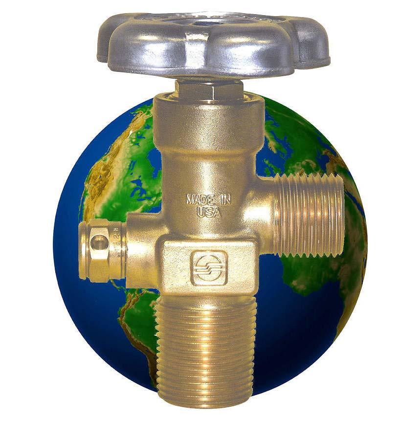
Series Valves Valves. Introducing the next generation of Global Valves for High-Pressure Applications Sherwood s new GVH Series!
|
|
|
- Hester Richardson
- 6 years ago
- Views:
Transcription


, CGA701 (Oxygen), CGA 680 & 677")
1 Series Valves Valves Series Introducing the next generation of Global Valves for High-Pressure Applications Sherwood s new GVH Series! Leak rate 10 times better than the industry standard for extreme environments. The Sherwood Global Valve is worldrenown for quality and variety of options to meet the needs of the global industrial gas market. Our new GVH Series features a new, heavy-duty design for highpressure applications New, Improved Features: Heavy Duty, Industrial Strength Reduced Internal Stress Zones Innovative Valve Core Design Optimized Bonnet Assembly Enhanced Pressure Relief Design Reliable Dual O-Ring and Back-Up Ring Design 100% Helium Leak 6000 psig Design Specifications: Leak Rate Integrity 1 X ,000 PSI Proof test: 9,750 PSI Burst Test: 15,000 PSI Temperature Range: -50 to +149 F Variety of Options for Global Applications: Outlets: CGA347 & CGA702 (Air), CGA701 (Oxygen), CGA 680 & 677 (Argon, Helium, Krypton, Neon, Nitrogen, Xenon), CGA695 & CGA703 (Hydrogen and other Flammable Gases) Inlets: ¾" NGT, ¾"+24 NGT; 25E Plating: Chrome Plating for Challenging Atmospheres Gauge Port Upon Special Request compgas@sherwoodvalve.com


2


3 SHERWOOD GLOBAL VALVE FEATURES Durable forged brass body, precisely machined internal components and design elements meet the most stringent International valve performance standards. Automated assembly and testing processes ensure exceptional quality. All Sherwood GV valves are 100% leak tested. Metal-to-metal seal below bonnet threads prevents pressure accumulation at top of valve body. High durometer back-up ring prevents extrusion of o-ring in extreme applications. Peroxide Curing of elastomeric seals enhances valve longevity. Direct drive stem design with optimized single o-ring seal reduces friction and operates at exceptionally low torque levels. The unitized plug design of the Pressure Relief Device (PRD) provides excellent flow characteristics. Optical Character Recognition technology utilized to verify appropriate burst disc pressure rating. Sherwood s exclusive webbed washer design protects burst disc during handling and bulk shipment. Inlet and Outlet thread configurations are available for a broad spectrum of Customer, Country and Code specifications. Internal plug threads protected from external impact by design. STANDARDS CONFORMANCE DESIGN SPECIFICATIONS CGA V-9 Standard for Gas Cylinder Valves Maximum Working Pressure 6,000 PSIG 413 BAR CGA S1.1 Standard for Pressure Relief Devices Burst Pressure 15,000 PSIG 1,035 BAR CGA V-1 Compressed Gas Cylinder Valve Outlet and Operating Temperature Min: -50 F -45 C Inlet Specifications Max: 130 F 55 C ISO International Standard for Cylinder Valves Storage Temperature Min: -65 F -54 C Design Specifications Max: 155 F 68 C EN 849 International Standard for Cylinder Valves Design Specifications Leak Rate Internal/External 1X10⁻³ atm cc/s AS2473 Australian Standard for Compressed Gas Minimum Cycle Life 2000 Cycles Cylinder Valves TPED Transportable Pressure Equipment Directive Modules B & D Cv Flow Factor Standard: CO2 / Manifold:
4 Gas GV SERIES O-RING SEAL DESIGN INDUSTRIAL VALVES CGA Outlet Inlet Outlet Thread Size Thread Size Sherwood Part Number Air 0 psi TO 3,000 psi NGO RH Ext. ½ - 14 NGT GV34641-XX ¾ - 14 NGT GV34661-XX 1-11½ NGT GV34681-XX UNF GV34651-XX UNF GV34651-XX 3,001 psi TO 5,500 psi NGO RH Ext. ¾ - 14 NGT GV34761-XX (long nipple) 5,501 psi TO 7,500 psi NGO RH Int. ¾ - 14 NGT GV70261-XX Argon 0 psi TO 3,000 psi NGO RH Int. ½ - 14 NGT GV58041-XX ¾ - 14 NGT GV58061-XX 1-11½ NGT GV58081-XX UNF GV58051-XX UNF GV58051-XX 3,001 psi TO 5,500 psi NGO RH Int. ¾ - 14 NGT GV68061-XX 5,501 psi TO 7,500 psi NGO LH Ext. ¾ - 14 NGT GV67761-XX Carbon Dioxide 0 psi TO 3,000 psi NGO RH Ext. ½ - 14 NGT GV32041-XX ¾ - 14 NGT GV32061-XX 1-11½ NGT GV32081-XX UNF GV32051-XX UNF GV32051-XX Carbon Monoxide 0 psi TO 3,000 psi NGO LH Ext. ½ - 14 NGT GV35045-XX ¾ - 14 NGT GV35065-XX 1-11½ NGT GV35085-XX UNF GV35055-XX UNF GV35055-XX 3,001 psi TO 5,500 psi NGO LH Int. ¾ - 14 NGT GV69565-XX 5,501 psi TO 7,500 psi NGO LH Int. ¾ - 14 NGT GV70365-XX Helium 0 psi TO 3,000 psi NGO RH Int. ½ - 14 NGT GV58041-XX ¾ - 14 NGT GV58061-XX 1-11½ NGT GV58081-XX UNF GV58051-XX UNF GV58051-XX 3,001 psi TO 5,500 psi NGO RH Int. ¾ - 14 NGT GV68061-XX 5,501 psi TO 7,500 psi NGO LH Ext. ¾ - 14 NGT GV67761-XX Hydrogen 0 psi TO 3,000 psi NGO LH Ext. ½ - 14 NGT GV35045-XX ¾ - 14 NGT GV35065-XX 1-11½ NGT GV35085-XX UNF GV35055-XX UNF GV35055-XX 3,001 psi TO 5,500 psi NGO LH Ext. ¾ - 14 NGT GV69565-XX 5,501 psi TO 7,500 psi NGO LH Int. ¾ - 14 NGT GV70365-XX Krypton 0 psi TO 3,000 psi NGO RH Int. ½ - 14 NGT GV58041-XX ¾ - 14 NGT GV58061-XX 1-11½ NGT GV58081-XX UNF GV58051-XX UNF GV58051-XX 3,001 psi TO 5,500 psi NGO RH Int. ¾ - 14 NGT GV68061-XX 5,501 psi TO 7,500 psi NGO LH Ext. ¾ - 14 NGT GV67761-XX
5 Gas GV SERIES O-RING SEAL DESIGN INDUSTRIAL VALVES CGA Outlet Inlet Outlet Thread Size Thread Size Sherwood Part Number Neon 0 psi TO 3,000 psi NGO RH Int. ½ - 14 NGT GV58041-XX ¾ - 14 NGT GV58061-XX 1-11½ NGT GV58081-XX UNF GV58051-XX UNF GV58051-XX 3,001 psi TO 5,500 psi NGO RH Int. ¾ - 14 NGT GV68061-XX 5,501 psi TO 7,500 psi NGO LH Ext. ¾ - 14 NGT GV67761-XX Nitrogen 0 psi TO 3,000 psi NGO RH Int. ½ - 14 NGT GV58041-XX ¾ - 14 NGT GV58061-XX 1-11½ NGT GV58081-XX UNF GV58051-XX UNF GV58051-XX 3,001 psi TO 5,500 psi NGO RH Int. ¾ - 14 NGT GV68061-XX 5,501 psi TO 7,500 psi NGO LH Ext. ¾ - 14 NGT GV67761-XX Nitrous Oxide 0 psi TO 3,000 psi NGO RH Ext. ½ - 14 NGT GV32641-XX ¾ - 14 NGT GV32661-XX 1-11½ NGT GV32681-XX UNF GV32651-XX UNF GV32651-XX Oxygen 0 psi TO 3,000 psi NGO RH Ext. ½ - 14 NGT GV54041-XX ¾ - 14 NGT GV54061-XX 1-11½ NGT GV54081-XX UNF GV54051-XX UNF GV54051-XX 3,001 psi TO 4,000 psi NGO RH Ext.. ¾ - 14 NGT GV57761-XX 4,001 psi TO 5,500 psi NGO RH Ext. ¾ - 14 NGT GV70161-XX Sulfur Hexafluoride 0 psi TO 3,000 psi NGO LH Int. ½ - 14 NGT GV59041-XX ¾ - 14 NGT GV59061-XX 1-11½ NGT GV59081-XX UNF GV59051-XX UNF GV59051-XX Xenon 0 psi TO 3,000 psi NGO RH Int. ½ - 14 NGT GV58041-XX ¾ - 14 NGT GV58061-XX 1-11½ NGT GV58081-XX UNF GV58051-XX UNF GV58051-XX 3,001 psi TO 5,500 psi NGO RH Int. ¾ - 14 NGT GV68061-XX 5,501 psi TO 7,500 psi NGO LH Ext. ¾ - 14 NGT GV67761-XX OPTIONS 4 & 7 & 24 threads oversize inlets: To order, add -4 or -7 or -24 to the end of the part number. e.g. GV35061-XX becomes GV35061-XX-7 Chrome Plating: To order, add letter A after letters GV in the part number. e.g. GV34661-XX becomes GVA34661-XX Lexan polycarbonate handwheels: To order, add suffix LX to the end of the part number. e.g. GV34661-XX becomes GV34661-XXLX Fusible backed pressure relief devices in 165 F or 212 F nominal melting temperatures: To order, change 1 in the part number to 4 (165 F) or to 5 (212 F). e.g. GV35061-XX becomes GV35064-XX for 165 F, or GV35065-XX for 212 F NOTE: GV valves are not approved for CNG service. Not all valves are available in all configurations. Contact factory for availability. Orders may be subject to minimum quantities.
6 SELECTION OF PRESSURE RELIEF DEVICES -XX CYLINDER SERVICE PRESSURE D.O.T. Exemption Cylinders PSIG D.O.T. Spec 3A, 3AA, 3AL Cylinders PSIG International Cylinders BAR DISC RUPTURE RANGE 160 F Min Max CG-1 Frangible Disc No Fuse Metal PRESSURE RELIEF DEVICE CG-4 ** Frangible Disc 165 F Fuse Metal CG-5 ** Frangible Disc 212 F Fuse Metal P625-19N9-26 P625-19X9-26M P625-19X9-26W P625-19N9-28 P625-19X9-28M P625-19X9-28W P625-19N9-32 P625-19X9-32M P625-19X9-32W P625-19N9-35 P625-19X9-35M P625-19X9-35W P625-19N9-38 P625-19X9-38M P625-19X9-38W P625-19N9-39 P625-19X9-39M P625-19X9-39W P625-19N9-43 P625-19X9-43M P625-19X9-43W P625-19N9-46 P625-19X9-46M P625-19X9-46W P625-19N9-47 P625-19X9-47M P625-19X9-47W P625-19N9-48 P625-19X9-48M P625-19X9-48W P625-19N9-50 P625-19X9-50M P625-19X9-50W / P625-19N9-55 P625-19X9-55M P625-19X9-55W P625-19N9-63 P625-19X9-63M P625-19X9-63W P625-19N9-65 P625-19X9-65M P625-19X9-65W P625-19N9-71 P625-19X9-71M P625-19X9-71W P625-19N9-78 P625-19X9-78M P625-19X9-78W P625-19N9-85 P625-19X9-85M P625-19X9-85W P625-19N9-95 P625-19X9-95M P625-19X9-95W **Copper Disc must be used for Hydrogen Service X = N for Nickel Disc or C for Copper Disc MATERIALS OF CONSTRUCTION FOR GV SERIES INDUSTRIAL AND CHROME PLATED VALVES Description Part Number Materials of Construction Body N/A Forged Brass UNS Alloy #37700/Chrome Plating when applicable. Bonnet Free Machining Brass UNS Alloy #36000/Chrome Plating when applicable. Handwheel 1919A Aluminum A380 Handwheel Nut Steel Class 8, Zinc Plating Lower Plug /1400-4A Leaded Naval Brass C48500 Lower Plug Seat / A Nylon Zytel 101 PRD See Chart Above Plug: Free Machining Brass UNS Alloy #36000/ Chrome Plating when applicable. Rupture Disc: Nickel Alloy 201; Copper UNS Webbed Seal Gasket: Copper Dead Soft C11000 Stem Free Machining Brass UNS Alloy #36000 O-Ring G011EP Ethylene Propylene Back up O-Ring A Ethylene Propylene Thrust Washer Delrin 500 AF INLET O-RING FOR STRAIGHT THREADED GV SERIES INDUSTRIAL AND CHROME PLATED VALVES Size Part Number Material Part Number Material UNF G208A Buna G208T Teflon UNF G210-9 Buna-N G210-T Teflon UNF G216A Buna 70 Durometer LUBRICANTS Christo-Lube MCG-111 Turmoxygen LC027 Used in valves for all Industrial Gas Applications Used in valves for Oxygen Service TORQUE VALUES FOR GV SERIES INDUSTRIAL AND CHROME PLATED VALVES Closing 5400 PSIG Inlet Pressure in. lbs. Operating 5400 PSIG Inlet Pressure in. lbs. Bonnet Installation Torque ft. lbs. Handwheel Nut Installation Torque in. lbs. PRD Installation Torque ft. lbs.
7 REPAIR INSTRUCTIONS FOR GV SERIES INDUSTRIAL AND CHROME PLATED VALVES DISASSEMBLY OF VALVE 1. Place the valve assembly into a vise or similar holding fixture, taking care not to damage the inlet or outlet threads. The holding fixture must securely grip the valve body on the wrench flats so that no damage is done to the internal bores, external threads, outlet, or pressure relief device. 2. Chamber a. Using a 13 mm socket, remove the handwheel nut from the handwheel by turning it counter clockwise. b. Remove the handwheel from the stem square. c. Using an 11/16 socket wrench or hex box wrench, remove the bonnet by turning it counter clockwise. The stem subassembly with o-ring and back-up o-ring may remove with the bonnet. If not, remove the stem subassembly from the valve after the bonnet. d. Being careful not to scratch the bonnet sealing surface in the valve body, use a square drive to remove the lower plug from the valve chamber, by turning it counter clockwise. 3. Pressure Relief Device a. Being careful not to scratch the sealing surface of the valve body, remove the pressure relief device by turning it counter clockwise using a 5/8 hex box wrench or socket. INSPECTION OF VALVE AND COMPONENTS 1. Valve Body a. Inspect the valve body chamber for dirt, debris or damage. Where possible, blow out the valve body chamber using clean, dry, Compressed Air or Nitrogen to remove any foreign particles. b. If the valve body is damaged, do not attempt to repair. Order a new valve assembly. 2. Components a. Always discard the bonnet and stem subassembly and the lower plug. Order replacement parts. NOTE: The lower plug replacement must correspond with the valve body and its relative application. For example, standard valves have a.125 or.156 through hole in the body which uses a nylon seat diameter that is relative to that size, part number Carbon dioxide and manifold valves except for oxygen have a.272 through hole in the body and use a nylon seat that is relative to that size, part number A. b. Handwheels should only be reused if in good condition. Discard handwheels if damaged. c. Inspect the pressure relief device threads for damage. Inspect the rupture disc and the webbed washer for scratches. Discard this component if damaged and order replacement parts. ASSEMBLY OF VALVE 1. Chamber a. Apply 3 dabs of lubricant around the perimeter of the lower plug threads, approximating the size of a pencil eraser for each. Locate lubricant toward the lower most threads closest to the crimped seat but using care not to get lubricant on the nylon seat. NOTE: Use Turmoxygen LC027 lubricant for oxygen service. Use Christo- Lube MCG-111 lubricant for all other gas applications. b. Being careful not to damage the bonnet sealing surface in the valve body, install the new lower plug into the chamber, seat first and tighten using a square drive until it is fully seated. c. Engage the new bonnet and stem subassembly into the valve body and hand tighten by turning clockwise. Rotate stem square until it becomes engaged in the lower plug. d. Using an 11/16 hex torque wrench, tighten the bonnet to ft. lbs. NOTE: A properly calibrated torque wrench must be used. Over torquing will damage the bonnet. e. Place the handwheel over the stem square. Thread the handwheel nut onto the stem thread and tighten to in. lbs. f. To ensure free and smooth operation, open and close the valve several times by turning the handwheel. 2. Pressure Relief Device (PRD) a. NOTE: Refer to CGA S-1.1 latest edition to select the correct pressure relief device type according to the cylinder pressure and application. b. Thread the proper pressure relief device on the PRD port until hand tight. c. Using a 5/8 socket and a calibrated torque wrench, tighten the PRD to ft. lbs. Over torquing will damage the PRD. TESTING OF ASSEMBLED VALVE 1. Thoroughly test each repaired valve assembly by inserting and tightening the valve assembly into a cylinder or suitable test fixture. 2. Pressurize the valve assembly with an inert gas to the working pressure of the cylinder of intended use. 3. With outlet suitably plugged, open the valve assembly by turning the handwheel counter clockwise. Using leak detection solution or equipment, check the bonnet, stem, and PRD for leaks. 4. Close the valve assembly by turning the handwheel clockwise. Remove the outlet plug and check for seat leakage through the outlet using proper leak detection solution or equipment. 5. If any leakage is detected, in the open or the closed position, the necessary repairs must be made before using the valve assembly.
 PARTS BREAKDOWN FOR GV SERIES INDUSTRIAL AND CHROME PLATED VALVES A B A. Handwheel Nut 1251-6 B.")
8 STAMPING CROSS REFERENCE FOR GV SERIES INDUSTRIAL AND CHROME PLATED VALVES B A C A. Inlet Thread Designation B. Outlet Specification C. Month/Year of Manufacture F D D. Week of Calendar Year E. International Standard for Cylinder Valve Design Specifications E F. Regulatory Approval (PI Mark) PARTS BREAKDOWN FOR GV SERIES INDUSTRIAL AND CHROME PLATED VALVES A B A. Handwheel Nut B. Handwheel 1919A C C. Bonnet and Stem Assembly (Oxygen) Includes: (All Others) Bonnet Back-Up O-ring O-ring Thrust Washer Stem D D. Lower Plug and Seat Assembly (Standard) Includes: A (CO2/Manifold) Lower Plug Seat E E. Pressure Relief Device P625-19X9-XX Includes: Plug Rupture Disc Webbed Seal Washer
 48 41 9 85-0 FX: (49) 48 41 9 85-1 ASIA Shah Alam, Malaysia PH: (60 3) 5191-3003 FX: (60 3) 5191-1472 AUSTRALIA Albury, New South Wales PH: (61 2) 60 402533 FX: (61 2) 60 402510")
9 For more information or to place an order: USA Washington, PA PH: (888) FX: (800) LATIN AMERICA Medellin, Columbia PH: (57) FX: (57) EUROPE Husum, Germany PH: (49) FX: (49) ASIA Shah Alam, Malaysia PH: (60 3) FX: (60 3) AUSTRALIA Albury, New South Wales PH: (61 2) FX: (61 2) SWDGLOBALVALVE_10_2009 Copyright 2008 SHERWOOD VALVE LLC, ALL RIGHTS RESERVED.

10 Protect the integrity of gas cylinder content without the high cost of purging, evacuating and cleaning.

11 GRPV SERIES FEATURES Durable forged brass body, precisely machined internal components and design elements meet the most stringent International valve performance standards. Automated assembly and testing processes ensure exceptional quality. All Sherwood GRPV valves are 100% leak tested. Sherwood GRPV valves are designed to retain approximately 30 to 50 psig pressure, maintaining the integrity of the cylinder contents against contaminants, even if the valve is left open. The unique combination of innovative design and quality construction offers protection of cylinder contents without the expense of a timeconsuming purge and clean cycle. Dynamic front piston seal design is not in direct contact with the flow passage during filling. Inlet and Outlet thread configurations are available for a broad spectrum of Customer, Country and Code specifications. The unitized plug design of the Pressure Relief Device (PRD) provides excellent flow characteristics. Optical Character Recognition technology utilized to verify appropriate burst disc pressure rating. Sherwood s exclusive webbed washer design protects burst disc during handling and bulk shipment. STANDARDS CONFORMANCE DESIGN SPECIFICATIONS CGA V-9 Standard for Gas Cylinder Valves Maximum Working Pressure 6,000 PSIG 413 BAR CGA S1.1 Standard for Pressure Relief Devices Burst Pressure 15,000 PSIG 1,035 BAR CGA V-1 Compressed Gas Cylinder Valve Min: -50 F Operating Temperature Outlet and Inlet Specifications Max: 130 F ISO International Standard for Cylinder Valves Design Specifications Storage Temperature Min: -65 F Max: 155 F ISO International Standard for Residual Pressure Valves Design Specifications EN 849 AS2473 TPED International Standard for Cylinder Valves Design Specifications Leak Rate Internal/External 1X10⁻³ atm cc/s Australian Standard for Compressed Gas Cylinder Valves Minimum Cycle Life 2,000 Cycles Transportable Pressure Equipment Directive Modules B & D Cv Flow Factor -45 C 55 C -54 C 68 C Standard: CO2 / Manifold:.28.50
12 Air Gas GRPV SERIES RESIDUAL PRESSURE VALVES CGA Outlet Inlet Outlet Thread Size Thread Size Sherwood Part Number 0 psi TO 3,000 psi NGO RH Ext. ½ - 14 NGT GRPV34641-XX Argon ¾ - 14 NGT GRPV34661-XX 0 psi TO 3,000 psi NGO RH Int. ½ - 14 NGT GRPV58041-XX ¾ - 14 NGT GRPV58061-XX 3,001 psi TO 5,500 psi NGO RH Int. ¾ - 14 NGT GRPV68061-XX Carbon Dioxide 0 psi TO 3,000 psi NGO RH Ext. ½ - 14 NGT GRPV32041-XX Helium ¾ - 14 NGT GRPV32061-XX 0 psi TO 3,000 psi NGO RH Int. ½ - 14 NGT GRPV58041-XX ¾ - 14 NGT GRPV58061-XX 3,001 psi TO 5,500 psi NGO RH Int. ¾ - 14 NGT GRPV68061-XX Hydrogen 0 psi TO 3,000 psi NGO LH Ext. ½ - 14 NGT GRPV35045-XX Nitrogen ¾ - 14 NGT GRPV35065-XX 0 psi TO 3,000 psi NGO RH Int. ½ - 14 NGT GRPV58041-XX ¾ - 14 NGT GRPV58061-XX 3,001 psi TO 5,500 psi NGO RH Int. ¾ - 14 NGT GRPV68061-XX Oxygen 0 psi TO 3,000 psi NGO RH Ext. ½ - 14 NGT GRPV54041-XX Sulfur Hexafluoride ¾ - 14 NGT GRPV54061-XX 0 psi TO 3,000 psi NGO LH Int. ½ - 14 NGT GRPV59041-XX OPTIONS 4 & 7 & 24 threads oversize inlets: To order, add -4 or -7 or -24 to the end of the part number. e.g. GRPV58061-XX becomes GRPV58061-XX-7 Chrome Plating: To order, add letter A after letters GV in the part number. e.g. GRPV58061-XX becomes GRPVA58061-XX Fusible backed pressure relief devices in 165 F or 212 F nominal melting temperatures: To order, change 1 in the part number to 4 (165 F) or to 5 (212 F). e.g. GRPV35061-XX becomes GRPV35064-XX for 165 F, or GRPV35065-XX for 212 F NOTE: GRPV Valves are not approved for CNG service. Not all valves are available in all configurations. Contact factory for availability. Orders may be subject to minimum quantities. NEW FOR UNF GRPV32051-XX ¾ - 14 NGT GRPV59061-XX
13 SELECTION OF PRESSURE RELIEF DEVICES -XX CYLINDER SERVICE PRESSURE D.O.T. Exemption Cylinders PSIG D.O.T. Spec 3A, 3AA, 3AL Cylinders PSIG International Cylinders BAR DISC RUPTURE RANGE 160 F Min Max CG-1 Frangible Disc No Fuse Metal PRESSURE RELIEF DEVICE CG-4 ** Frangible Disc 165 F Fuse Metal CG-5 ** Frangible Disc 212 F Fuse Metal P625-19N9-26 P625-19X9-26M P625-19X9-26W P625-19N9-28 P625-19X9-28M P625-19X9-28W P625-19N9-32 P625-19X9-32M P625-19X9-32W P625-19N9-35 P625-19X9-35M P625-19X9-35W P625-19N9-38 P625-19X9-38M P625-19X9-38W P625-19N9-39 P625-19X9-39M P625-19X9-39W P625-19N9-43 P625-19X9-43M P625-19X9-43W P625-19N9-46 P625-19X9-46M P625-19X9-46W P625-19N9-47 P625-19X9-47M P625-19X9-47W P625-19N9-48 P625-19X9-48M P625-19X9-48W P625-19N9-50 P625-19X9-50M P625-19X9-50W / P625-19N9-55 P625-19X9-55M P625-19X9-55W P625-19N9-63 P625-19X9-63M P625-19X9-63W P625-19N9-65 P625-19X9-65M P625-19X9-65W P625-19N9-71 P625-19X9-71M P625-19X9-71W P625-19N9-78 P625-19X9-78M P625-19X9-78W P625-19N9-85 P625-19X9-85M P625-19X9-85W P625-19N9-95 P625-19X9-95M P625-19X9-95W **Copper Disc must be used for Hydrogen Service X = N for Nickel Disc or C for Copper Disc MATERIALS OF CONSTRUCTION FOR GRPV SERIES RESIDUAL PRESSURE VALVES Description Part Number Materials of Construction Body N/A Forged Brass UNS Alloy #37700/Chrome Plating when applicable. Bonnet Free Machining Brass UNS Alloy #36000/Chrome Plating when applicable. Handwheel 1919A Aluminum A380 Handwheel Nut Steel Class 8, Zinc Plating Lower Plug /1400-4A Leaded Naval Brass C48500 Lower Plug Seat / A Nylon Zytel 101 Plug: Free Machining Brass UNS Alloy #36000/ Chrome Plating when applicable. PRD See Chart Above Rupture Disc: Nickel Alloy 201; Copper UNS Webbed Seal Gasket: Copper Dead Soft C11000 Stem Free Machining Brass UNS Alloy #36000 O-Ring G011EP Ethylene Propylene Back up O-Ring A Ethylene Propylene Thrust Washer Delrin 500 AF RPV Piston 1400RP-10 Forged Brass UNS Alloy #37700 RPV Plug 1400RPB-8 Free Machining Brass UNS Alloy #36000/Chrome Plating when applicable. RPV Spring 1400RP-7 Beryllium Copper Piston O-Ring G008EP9 Ethylene Propylene Piston Quad Ring G4011EP9 Ethylene Propylene RPV Plug O-Ring G017EP9 Ethylene Propylene INLET O-RING FOR STRAIGHT THREADED GRPV SERIES RESIDUAL PRESSURE VALVES Size Part Number UNF G216A (Buna 70 Durometer) 2200 North Main Street LUBRICANTS Christo-Lube MCG-111 Turmoxygen LC027 Used in valves for all Industrial Gas Applications Used in valves for Oxygen Service TORQUE VALUES FOR GRPV SERIES RESIDUAL PRESSURE VALVES Closing 5400 PSIG Inlet Pressure in. lbs. ( Nm) Operating 5400 PSIG Inlet Pressure in. lbs. ( Nm) Bonnet Installation Torque ft. lbs. (68-81 Nm) Handwheel Nut Installation Torque in. lbs. ( Nm) PRD Installation Torque ft. lbs. (34-47 Nm)
14 REPAIR INSTRUCTIONS FOR GRPV SERIES RESIDUAL PRESSURE VALVES 2200 North Main Street DISASSEMBLY OF VALVE 1. Place the valve assembly into a vise or similar holding fixture, taking care not to damage the inlet or outlet threads. The holding fixture must securely grip the valve body on the wrench flats so that no damage is done to the internal bores, external threads, outlet, or pressure relief device. 2. Chamber a. Using a 13 mm socket, remove the handwheel nut from the handwheel by turning it counter clockwise. b. Remove the handwheel from the stem square. c. Using an 11/16 socket wrench or hex box wrench, remove the bonnet by turning it counter clockwise. The stem subassembly with o-ring and back-up o-ring may remove with the bonnet. If not, remove the stem subassembly from the valve after the bonnet. d. Being careful not to scratch the bonnet sealing surface in the valve body, use a square drive to remove the lower plug from the valve chamber, by turning it counter clockwise. 3. Pressure Relief Device a. Being careful not to scratch the sealing surface of the valve body, remove the pressure relief device by turning it counter clockwise using a 5/8 hex box wrench or socket. INSPECTION OF VALVE AND COMPONENTS 1. Valve Body a. Inspect the valve body chamber for dirt, debris or damage. Where possible, blow out the valve body chamber using clean, dry, Compressed Air or Nitrogen to remove any foreign particles. b. If the valve body is damaged, do not attempt to repair. Order a new valve assembly. 2. Components a. Always discard the bonnet and stem subassembly and the lower plug. Order replacement parts. NOTE: The lower plug replacement must correspond with the valve body and its relative application. For example, standard valves have a.125 or.156 through hole in the body which uses a nylon seat diameter that is relative to that size, part number Carbon dioxide and manifold valves except for oxygen have a.272 through hole in the body and use a nylon seat that is relative to that size, part number A. b. Handwheels should only be reused if in good condition. Discard handwheels if damaged. c. Inspect the pressure relief device threads for damage. Inspect the rupture disc and the webbed washer for scratches. Discard this component if damaged and order replacement parts. ASSEMBLY OF VALVE 1. Chamber a. Apply 3 dabs of lubricant around the perimeter of the lower plug threads, approximating the size of a pencil eraser for each. Locate lubricant toward the lower most threads closest to the crimped seat but using care not to get lubricant on the nylon seat. NOTE: Use Turmoxygen LC027 lubricant for oxygen service. Use Christo-Lube MCG-111 lubricant for all other gas applications. b. Being careful not to damage the bonnet sealing surface in the valve body, install the new lower plug into the chamber, seat first and tighten using a square drive until it is fully seated. c. Engage the new bonnet and stem subassembly into the valve body and hand tighten by turning clockwise. Rotate stem square until it becomes engaged in the lower plug. d. Using an 11/16 hex torque wrench, tighten the bonnet to ft. lbs. NOTE: A properly calibrated torque wrench must be used. Over torquing will damage the bonnet. e. Place the handwheel over the stem square. Thread the handwheel nut onto the stem thread and tighten to in. lbs. f. To ensure free and smooth operation, open and close the valve several times by turning the handwheel. 2. Pressure Relief Device (PRD) a. NOTE: Refer to CGA S-1.1 latest edition to select the correct pressure relief device type according to the cylinder pressure and application. b. Thread the proper pressure relief device on the PRD port until hand tight. c. Using a 5/8 socket and a calibrated torque wrench, tighten the PRD to ft. lbs. Over torquing will damage the PRD. TESTING OF ASSEMBLED VALVE 1. Thoroughly test each repaired valve assembly by inserting and tightening the valve assembly into a cylinder or suitable test fixture. 2. Pressurize the valve assembly with an inert gas to the working pressure of the cylinder of intended use. 3. With outlet suitably plugged, open the valve assembly by turning the handwheel counter clockwise. Using leak detection solution or equipment, check the bonnet, stem, and PRD for leaks. 4. Close the valve assembly by turning the handwheel clockwise. Remove the outlet plug and check for seat leakage through the outlet using proper leak detection solution or equipment. 5. If any leakage is detected, in the open or the closed position, the necessary repairs must be made before using the valve assembly. NOTE: Residual check components should NOT be disassembled. For service or repair, contact factory.
15 STAMPING CROSS REFERENCE FOR GRPV SERIES RESIDUAL PRESSURE VALVES A B C A. Inlet Thread Designation B. Outlet Specification F C. Month/Year of Manufacture D. Week of Calendar Year E D E. International Standard for Cylinder Valve Design Specifications F. Regulatory Approval (PI Mark) PARTS BREAKDOWN FOR GRPV SERIES RESIDUAL PRESSURE VALVES


16 ADAPTERS FOR GRPV SERIES Adapter With Retractable Pin TLG580SLW * CGA 580 TLG590SLW * CGA 590 Adapter provides maximum operating flexibility to fill or evacuate a cylinder with either a conventional valve or a GRPV. Engage the Pin Locking Tool (see below), rotate the tool clockwise to depress the pin for use with a conventional valve. Or, rotate the tool counterclockwise to release the pin for use with a GRPV valve. The adapter incorporates an o-ring seal for a hand tight connection. Adapter With Fixed Pin TLG320W CGA 320 TLG346S CGA 346 TLG350S CGA 350 TLG540S CGA 540 TL580D * CGA 580 TL590D * CGA 590 Adapter features a rigid-mounted pin for use on manifolds dedicated to filling cylinders with Sherwood GRPV valves. *Adapters can be used with TV RPV also. *Adapters can be used with TV RPV also. Understanding the Adapter part numbers: TLG=Tool for Global Valve L=Spring Loaded B=Bagged and O 2 Cleaned S=Stainless Steel W=Washer or O-ring Seal Pin Locking Tool TL580B Used with retractable pin adapter. Checking Rod TL580C Gas cylinders can be checked for content-integrity by simply inserting the checking rod and pushing against the resistance of the check valve. The sound of escaping gas indicates residual cylinder pressure.
 4 3525229 FX: (57) 4 3525229 EUROPE Husum, Germany PH: (49) 48 41 9 85-0 FX:")
 60 402533 FX: (61 2) 60 402510 SWDGRPV_10_09 Copyright 2008 SHERWOOD VALVE LLC, ALL RIGHTS")
17 For more information or to place an order: USA Washington, PA PH: (888) FX: (800) LATIN AMERICA Medellin, Columbia PH: (57) FX: (57) EUROPE Husum, Germany PH: (49) FX: (49) ASIA Shah Alam, Malaysia PH: (60 3) FX: (60 3) AUSTRALIA Albury, New South Wales PH: (61 2) FX: (61 2) SWDGRPV_10_09 Copyright 2008 SHERWOOD VALVE LLC, ALL RIGHTS RESERVED.
Sherwood Valve LLC EVERY COUNTRY EVERY CUSTOMER EVERY CODE. GVSERIES Industrial and Chrome Plated Precision Valves
 Sherwood Valve LLC EVERY COUNTRY EVERY CUSTOMER EVERY CODE GVSERIES Industrial and Chrome Plated Precision Valves SHERWOOD GLOBAL VALVE FEATURES Durable forged brass body, precisely machined internal components
GRPV Series Residual Pressure Valves
 Residual pressure valve designed to protect cylinder and contents. Key Features & Benefits Prevents backflow of impurities and foreign substances Automated assembly and testing processes ensure exceptional
2200 North Main Street Washington, PA PH: FX:
 2200 North Main Street 2200 North Main Street KVAB SERIES MEDICAL VALVES All valves MRI compatible - approved to 3 Tesla. Nominal stroke is 1.5 turns. Full flow at ⅓ turn. Strong, durable body is made
Chlorine Valves and Accessories
 Chlorine Valves and Accessories Chlorine Cylinder & Ton Container Valves Standard Chlorine Institute Design & Alternate Design 1 ALTERNATE VALVE DESIGN vs. STANDARD CHLORINE INSTITUTE VALVE DESIGN FOR
Wheel operated cylinder valve in O-ring seal design for carbon dioxide
 Wheel operated cylinder valve in O-ring seal design for carbon dioxide SWN-12/C (simple valve) IWN-12/C (inline RPV) Robust construction and built to last High flow and reliable performance Low torque
Compressed Gas Equipment
 Compressed Gas Equipment 1-888-50VALVE (508-258) TABLE OF CONTENTS PRODUCT INFORMATION AND ORDERING AV Series Acetylene Valve 01 AVB & AVMC Series Acetylene Valves 0 AV Series for WB Acetylene Valves 5
Chlorine Gas Valves Robust Valve
 Robust Valve Robust Valve The Sherwood Exclusive Robust Valve features a heavy-duty body and packing nut for increased load carrying capacity and resistance against stress corrosion and cracking. Key Features
Handle operated, metal seated master shut off valve in O-ring seal design for high pressure gas manifold & piping system
 Handle operated, metal seated master shut off valve in O-ring seal design for high pressure gas manifold & piping system Exceeds industry standards Provides high flow and resistance to ignition in Oxygen
SHERWOOD VALVE CHLORINE GAS PRODUCTS
 SHERWOOD VALVE CHLORINE GAS PRODUCTS A History of Quality and Innovation For nearly a century, Sherwood has been the world s leading provider of system-critical compressed gas solutions serving blue-chip
Key operated cylinder valve in O-ring seal design for carbon dioxide
 Key operated cylinder valve in O-ring seal design for carbon dioxide SKN-12/C Robust construction High performance and ease of maintenance Resistant to stress corrosion cracking TPED Certification ( mark)
Key operated cylinder valve in O-ring seal design for acetylene service
 Key operated cylinder valve in O-ring seal design for acetylene service KHO-10/D (side outlet) KVO-10/D (top outlet) Resistant to acetylene detonation Robust construction for safe and reliable operation
Escape Cylinder and Valve
 Escape Cylinder and Valve MAINTENANCE AND REPAIR TAL 1601 (L) Rev. 2 MSA 2016 Prnt. Spec. 10000005389 (I) Mat. 10064389 Doc. 10064389 CYLINDER COMPONENTS Item Part No. Description 818159 5 Minute, Aluminum
S H E R W O O D M A S T E R D I S T R I B U T O R
 Sherwood Residual Pressure Valve see page 34A 28-33 for Various Gases including Carbon Dioxide and Medical Oxygen R AT E R M A N N www.rmiorder.com sales@rmimfg.com INDEX VALVES Ball Valves... 37B 2-9
Cylinder and Valve: AirHawk II Air Mask
 Cylinder and Valve: AirHawk II Air Mask MAINTENANCE AND REPAIR MSA 011 (L) Rev. 0 MSA 2010 Prnt. Spec. 10000005389(I) Mat. 10104218 Doc. 10104218 Parts List Cylinder Replacement Kits Item P/N Description
FIBA Technologies, Inc. PARTS CATALOG. For seamless pressure vessels and gas storage and transport systems
 PARTS CATALOG For seamless pressure vessels and gas storage and transport systems FIBA Technologies, Inc. Over 50 Years of Integrity, Reliability, and Innovation DO NOT PRINT - PAGE INTENTIONALLY LEFT
INSTRUCTION AND MAINTENANCE MANUAL FR95 PRESSURE REGULATOR
 Enidine / Conoflow 105 Commerce Way Westminster, SC 29693 Tel: (864) 647-9521 Fax: (864) 647-7993 WARNING Conoflow s products are designed and manufactured using materials and workmanship required to meet
aero 2 -IOM aero 2 ACTUATOR - INSTALLATION, OPERATION & MAINTENANCE MANUAL
 Instruction DP00226 May 2015 IMPORTANT SAFETY WARNINGS A. Before carrying out any repair or maintenance on the actuator, make sure that the pressure supply lines and electrical connections have been safely
CYLINDER VALVES. Assembly & Maintenance Guide
 CYLINDER VALVES Assembly & Maintenance Guide TABLE OF CONTENTS Topic Page Yoke Connection Valves...................................2 6300 Series Valves.......................................3 Service Procedures.......................................4
1 2-Inch Station Outlet Valves
 ADI 1089M Certified ISO 9001:2000 1 2-Inch Station Outlet Valves Non-Return Type INSTALLATION AND OPERATION INSTRUCTIONS Before Installing or Operating, Read and Comply with These Instructions Controls
INSTRUCTION AND MAINTENANCE MANUAL GFH45 PRESSURE REGULATOR
 Enidine / Conoflow 105 Commerce Way Westminster, SC 29693 Tel: (864) 647-9521 Fax: (864) 647-7993 WARNING Conoflow s products are designed and manufactured using materials and workmanship required to meet
Series CAV-06. (ValveasperP17,Edition-4)
") Key Operated Valves in Packed design for Chlorine and Liquefiable Corrosive Gases (ValveasperP17,Edition-4) (ValveasperENISO1097:006) (ValveasperIS34:00) Precision machining for high performance Metal
Key Operated Valves in Packed design for Chlorine and Liquefiable Corrosive Gases (ValveasperP17,Edition-4) (ValveasperENISO1097:006) (ValveasperIS34:00) Precision machining for high performance Metal
Audi-Larm TM Audible Alarm: AirHawk II Air Mask
 Audi-Larm TM Audible Alarm: AirHawk II Air Mask MAINTENANCE AND REPAIR MSA 011 (L) Rev. 0 MSA 2010 Prnt. Spec. 10000005389(I) Mat. 10104323 Doc. 10104323 REPLACEMENT KITS AND PARTS LIST Item P/N Description
Technology for a Better Future. VALVES International Edition.
 www.genstartech.com VALVES International Edition (Needle Valve, Metering Valve, Ball Valve, Diaphragm Valve, Gauge Valve, Check Valve, Excess Flow Valve, Relief Valve, Cylinder Valve) Technology for a
PARTS, SERVICE & REPAIR BULLETIN
 PARTS, SERVICE & REPAIR BULLETIN ESS3 ESS4 ESS7 EST4 ESL4 ELC4 Pressure Regulators Revision: D Issue Date: March 20 Form No.: 0056-966 INDEX Section Models Page ESS3 & ESS4 0 2 3 Future EDGE Models ESS7,
Baumann Mikroseal Control Valve
 Instruction Manual 81000 Valve Baumann 81000 Mikroseal Control Valve Contents Introduction... 1 Scope of Manual... 1 Safety Precautions... 2 Maintenance... 3 Installation... 3 Air Piping... 4 Flow Direction...
Series Regulators - Pressure Reducing
 Regulators - Pressure Reducing D26100538X012 Specifications For other materials or modifications, please consult TESCOM. Operating Parameters Pressure rating per criteria of ANSI/ASME B31.3 Maximum Inlet
SERIES. CRYOGENIC/PRESSURE BUILD REGULATOR 3/8 and 1/2" NPT, BSPT Inlet 400 Psig (28 Bar) Description
 Description") CRYOGENIC/PRESSURE BUILD REGULATOR 3/8 and 1/2" NPT, BSPT Inlet 400 Psig (28 Bar) CR Description The Generant Series CR Cryogenic Regulator provides high flow during Cryogenic Vessel Pressure Build function
CRYOGENIC/PRESSURE BUILD REGULATOR 3/8 and 1/2" NPT, BSPT Inlet 400 Psig (28 Bar) CR Description The Generant Series CR Cryogenic Regulator provides high flow during Cryogenic Vessel Pressure Build function
0-800 psi Carbide Seat Fluid Pressure Regulator
 Instruction Sheet P/N 0350C 0-800 psi Carbide Seat Fluid Pressure Regulator Description The Nordson 0-800 psi carbide seat fluid pressure regulator is designed for use with general liquid coatings. The
Hard Seat Fluid Pressure Regulator
 Instruction Sheet P/N 04742-02 Description The Nordson hard seat fluid pressure regulator is designed for use with abrasive coatings. The regulator body is constructed of stainless steel with a nickel-plated
Soft Seat Fluid Pressure Regulator
 Instruction Sheet P/N 04622F Description The Nordson soft seat fluid pressure regulator is designed for use with nonabrasive liquid coatings. The regulator body is constructed of stainless steel with a
Masoneilan* 51/52/53 Series
 Technical Specifications Rev.E - 01/2018 Masoneilan* 51/52/53 Series Cylinder Actuator BHGE Data Classification: Public Conversion Table All the USCS values are converted to metric values using the following
HD and HDL Single-Stage Non-Lube Gas Compressors
 COMPRESSORS CB-324 2013/05 Ethylene Ethylene Oxide HCFC s Helium n-heptane n-hexane Hydrogen Hydrogen Chloride Hydrogen Sulfide Isobutane Isobutene Isobutylene Isopentane Methane Methanol Methyl Acetylene
packless valves Packless Valves Index Bellows & Diaphragm
 Packless Valves Bellows & Diaphragm Index 0300 Series (Bellows) 1 4100 Series (Bellows) 4 4200 Series (Bellows) 8 4500 Series (Bellows) 11 4600 Series (Diaphragm) 13 DV1 Series (Diaphragm) 17 HOKE Inc.
0-500 PSI Soft Seat Fluid Pressure Regulator
 Instruction Sheet P/N 0953A Description The Nordson 0-500 psi soft seat fluid pressure regulator is designed for use with nonabrasive liquid coatings. The regulator body is constructed of stainless steel
OPERATION MANUAL. ALUMINUM Models. 316 S.S. Models NTG25 NOMAD TRANS-FLO AIR-OPERATED DOUBLE DIAPHRAGM PUMPS. A JDA Global Company. 1/14 rev.
 OPERATION MANUAL NTG25 NOMAD TRANS-FLO AIR-OPERATED DOUBLE DIAPHRAGM PUMPS ALUMINUM Models 316 S.S. Models A JDA Global Company 1/14 rev. 3 CAUTION SAFETY POINTS TEMPERATURE LIMITS: Neoprene -17.8 C to
Baumann Sanitary Angle Control Valve
 Baumann 83000 Sanitary Angle Control Valve Contents Introduction... 1 Scope of Manual... 1 Safety Precautions... 2 Educational Services... 2 Maintenance... 3 Installation... 3 Air Piping... 4 Flow Direction...
KHR Series Regulators
 KHR Series Regulators Maintenance Instructions Kit Contents retainer Poppet Poppet spring Poppet damper Outer body seal Inner body seal Upper piston seal seal backup ring Main piston seal vent seal Self-vent
Valves and Equipment
 DOT/ASME LPG VALVES & TANK EQUIPMENTContainer Valves and Equipment Multi-Service Valve PG. 34 420 Multivalve PG. 35 Underground Multi-Service Valve PG. 36 Underground Multi-Service Valve with Integrated
Part # Regulator Rebuild Kit for SuperFlow and SuperFlow 350 Regulators
 Part #525-309 Regulator Rebuild Kit for SuperFlow and SuperFlow 350 Regulators Tools Required Part Number Description Qty 510-011 O-ring 1 510-014 O-ring 1 510-552 Exhaust Valve 1 510-553 Diaphragm 1 520-032
VALVES & MEASUREMENT. TEXSTEAM Super G Plug Valves TEXSTEAM
 TEXSTEAM Super G Plug Valves TEXSTEAM 2 TEXSTEAM TABLE OF CONTENTS Introduction... 4 Design Standards... 5 Parts List... 6 Accessories and Repair Kits... 7 Reduced Port Dimensions and Weights... 8 Full
OPERATION MANUAL NT50 NOMAD TRANS-FLO AIR-OPERATED DOUBLE DIAPHRAGM PUMPS. A JDA Global Company. 7/11 rev. 1
 OPERATION MANUAL NT50 NOMAD TRANS-FLO AIR-OPERATED DOUBLE DIAPHRAGM PUMPS A JDA Global Company 7/11 rev. 1 CAUTION SAFETY POINTS TEMPERATURE LIMITS: Neoprene -17.8 C to 93.3 C 0 F to 200 F Buna-N -12.2
Installation, Operation and Maintenance Instructions
 Installation, Operation and Maintenance Instructions MODEL 5520 June 2002 1.0 GENERAL... 2 Model Number Information... 2 Features... 3 Specifications... 4 Table 1A. Flow Coefficients (C V ), Modified Percent
Valve accessories. Inspired By Challenge
 Inspired By Challenge Accessories Locking device Fugitive Emission (FE) Spring Return Handle (SRH) Locking device Compare to standard sliding plate locking devices which are commonly used in the market,
Automatic Changeover Medical Manifold Installation, Operation and Maintenance Manual
 Automatic Changeover Medical Manifold Installation, Operation and Maintenance Manual Andersen Medical Gas 12 Place Lafitte Madisonville, LA 70447 http://www.themedicalgas.com 1-866-288-3783 Model Number:
Series 11 Miniature Pneumatic Solenoid Valve 15mm Solenoid Valve
 Series 11 Miniature Pneumatic Solenoid Valve 15mm Solenoid Valve Typical Applications Oxygen Conservers Oxygen Concentrators Compression Therapy Gas Chromatography Insufflators Medical & Analytical Gas
HYDRAULIC PUMP. INSTALLATION, OPERATION, & MAINTENANCE MANUAL MAINTENANCE MANUAL #: MM-HP Rev. A Page 1 of 12
 INSTALLATION, OPERATION, & #: MM-HP001 4-20-09 Rev. A Page 1 of 12 HYDRAULIC PUMP PART NUMBER HP46982ALSL & HP46982SL HYDRAULIC PUMP MM-HP001 Rev. A Page 2 of 12 Table of Contents 1.0 General Page 3 2.0
Cash Valve B SERIES PRESSURE REGULATORS. ISSUED - JANUARY 1999 CAVMC-0509-US-0208 ISO 9001 Certified
 Cash Valve B SERIES REGULATORS ISSUED - JANUARY 1999 CAVMC-09-US-0208 ISO 9001 Certified GENERAL INFORMATION / REGULATORS B SERIES VALVES DESCRIPTION The Cash Valve Series B pressure reducing and regulating
YARWAY HANCOCK Y-PATTERN FORGED STEEL GLOBE STOP VALVES SERIES 4000
 Direct contact and metal-to-metal seating make this Y-pattern globe stop valve ideal for most shut-off applications. FEATURES All valves feature integral Stellite hardfacing on both body and disc seating
HIGH PRESSURE CONTROL VALVE PISTON BALANCED
 PISTON BALANCED All Rights Reserved. All contents of this publication including illustrations are believed to be reliable. And while efforts have been made to ensure their accuracy, they are not to be
Back Pressure Regulator
 Instruction Sheet P/N 108652H Description The Nordson back pressure regulator is a spring-loaded, hand-operated fluid pressure regulator designed for use with general liquid coating materials. The regulator
TECHNICAL DATA 1-1/2 (dn40)
") July 1, 2011 Deluge Valves 209a DESCRIPTION The Viking Model E-3 1-1/2 Deluge Valve is a quick-opening, differential type flood valve with a rolling diaphragm clapper. The deluge valve is used to control
July 1, 2011 Deluge Valves 209a DESCRIPTION The Viking Model E-3 1-1/2 Deluge Valve is a quick-opening, differential type flood valve with a rolling diaphragm clapper. The deluge valve is used to control
CASH VALVES TYPE G-4 PRESSURE REGULATORS
 A self-actuating pilot operated pressure reducing valve handling air, gas and steam and accurate to within ½% up to 3" and 1% for sizes to 6 FEATURES Extremely compact design enables use of a smaller regulator.
MODEL 5540 CONTENTS. Installation, Operation and Maintenance Instructions 1.0 GENERAL
 Installation, Operation and Maintenance Instructions MODEL 5540 Sep 20 CONTENTS.0 GENERAL. Model Number---------------------------------------------------------------------------------------------------------------
Purging Air From Divider Block Lubrication Systems
 FROST ENGINEERING SERVICE Purging Air From Lubrication Systems A D I V I S I O N O F G E C S E Y S A L E S & S E R V I C E DESCRIPTION Divider block lubrication systems operate correctly only when all
Pressure Relief Valve Maintenance Manual
 Technical Manual 1098T Pressure Relief Valve Maintenance Manual Farris Engineering Division of Curtiss-Wright Flow Control Corporation TABLE OF CONTENTS - Manual Revision 0 Introduction & Safety Tips...
General Specifications
 General Specifications GS 22B01C53-01EN-A M-675, M-775 and M-678 5-Valve Manifolds for Natural Gas Differential Pressure INTRODUCTION The PGI 5-Valve manifolds are designed for natural gas service and
Baumann Sanitary Diaphragm Angle and Inline Control Valve
 Instruction Manual 84000 Valve Baumann 84000 Sanitary Diaphragm Angle and Inline Control Valve Contents Introduction... 1 Scope of Manual... 1 Safety Precautions... 2 Maintenance... 2 Flow Direction...
Ideal Installation. I & M Mark 67 (1/2 6 ) Control Line. Installation & Maintenance Instructions for Mark 67 Pressure Regulators
 Control Line. Installation & Maintenance Instructions for Mark 67 Pressure Regulators") I & M Mark (/ ) 0 Wasson Road Cincinnati, OH 0 USA Phone --00 Fax -8-00 info@richardsind.com www.jordanvalve.com Installation & Maintenance Instructions for Mark Pressure Regulators Warning: Jordan Valve
I & M Mark (/ ) 0 Wasson Road Cincinnati, OH 0 USA Phone --00 Fax -8-00 info@richardsind.com www.jordanvalve.com Installation & Maintenance Instructions for Mark Pressure Regulators Warning: Jordan Valve
Hydraulic Valves Needle Valves
 Table of Contents 1 Hydraulic Valves Needle Valves TMN Series FFG 2000 Series FFA 2000 Series 2-3 4-5 6-7 Check Valves C Series 8-9 Flow Controls TMF Series 10-11 Low Pressure Ball Valve S95 NPT Series
D I S T R I B U T E D V A L V E S. Super G Lubricated-Non-Lubricated Plug Valve TEXSTEAM
 Super G Lubricated-Non-Lubricated Plug Valve SUPER G EXCLUSIVE FEATURES Built and tested in accordance with API 6A, API 6D & B16. Lubricated and non-lubricated in same valve. Use it either way Metal-to
TOOLS NEEDED FOR REPAIR OF MK 14
 150 200 250 USE NO OIL 100 00 50 50 psi 00 MADE IN THE USA R Special Tools P/N 1-07-000 MK 1 Repair and Maintenance Guide FOR REPAIR OF MK 1 Quantity Part Number Description 2.00.127 Field handle 1 set.00.017
Models 910, 911, 916, 917, 920, 921, 927 ASME Section VIII, Air/Gas/
 Models 910, 911, 916, 917, 920, 921, 927 ASME Section VIII, Air/Gas/ Steam/Liquid, UV National Board Certified. Also available for Vacuum Service Model 921: Steel body and bonnet with plain lift lever
1. Valves shall conform to the latest version of AWWA Standard C-509 covering Resilient Seated gate Valves for Water Supply Service.
 KENNEDY KENNEDY VALVE MODEL VALVE KS-RW 1. Valves shall conform to the latest version of AWWA Standard C-509 covering Resilient Seated gate Valves for Water Supply Service. 2. The valves shall have a cast
Valve Accessories. Inspired By Challenge
 Valve Accessories Inspired By Challenge Accessories Locking device Fugitive Emission (FE) Spring Return Handle (SRH) Locking device Compare to standard sliding plate locking devices which are coonly used
Bulletin: Floating Ball Valve. Tartarini Floating Ball Valve. Introduction. Features and Benefits
 Tartarini Floating Ball Valve Bulletin: Floating Ball Valve May 2011 Figure 1. Tartarini Floating Ball Valve Introduction Tartarini Floating Ball Valve is a general-purpose valve. It is used for long range
Inline Adapters are Electro Polished to 10 Ra Max. 2 Valves supplied with Metal to Metal Face Seal connections have
 CRYOGENIC RELIEF VALVE (STAINLESS) 1/4" and 1/2" NPT -4 and -8 Metal To Metal Face Seal 1/4" and 1/2" Bi-Lok Dual Ferrule Tube 10-750 Psig (0.69-51.7 Bar) STAINLESSCRV Description The Generant Series Stainless
Model descriptions. Technical data. Pressure and Temperature Limits Models 19, 20, 20P: -60 to 406 F Models 19M, 20M, 20MP:
 VALVES & CONTROLS KUNKLE SAFETY AND RELIEF PRODUCTS Non-code Bronze Liquid Relief Valves Model descriptions Model 20 Model 19: All bronze, equipped with handwheel for easy adjustment within spring ranges.
Series A Floating Ball Valve Installation, Operation & Maintenance XXXX - X X X X X X X. Base Part Numbers. Trim Option Suffix Code
 Series A Floating Ball Valve Installation, Operation & Maintenance Base Part Numbers RATING 1 FP 2 RP 2 FP 3 RP 3 FP 4 RP 4 FP 1000 1102 1103 1104 1106 1105 1107 1500 1151 1152 1153 1154 1156 1155 1157
Formed Sampling Cylinders and Accessories Index amp ling cylinde HOKE Inc.
 Formed Sampling Cylinders and Accessories Index Sampling Cylinders 2 Design, Features, Applications Cylinder Accessories 3 Collars, Flanges, Caps, Carrying Handles Safety Relief Devices Cylinder Valves
5100 Series Inline Relief Valve 10 to 2,400 PSIG
 Fred C. Gilbert Co. 106 Norris Road Bakersfield, Ca. 93308 661-399-9569 fax 661-393-9654 5100 Series Inline Relief Valve 10 to 2,400 PSIG Features Zero Leakage to 95% of Cracking Pressure Positive Reseal
INSTALLATION, OPERATION AND MAINTENANCE MANUAL (IOM)
") INSTALLATION, OPERATION AND MAINTENANCE MANUAL (IOM) IOM-1088 03-16 Model 1088 Vacu-Gard Blanketing Valve ISO Registered Company SECTION I I. DESCRIPTION AND SCOPE The Model 1088 Vacu-Gard is a tank blanketing
INSTALLATION, OPERATION AND MAINTENANCE MANUAL (IOM) IOM-1088 03-16 Model 1088 Vacu-Gard Blanketing Valve ISO Registered Company SECTION I I. DESCRIPTION AND SCOPE The Model 1088 Vacu-Gard is a tank blanketing
CASH VALVES TYPE G-4 PILOT OPERATED PRESSURE REDUCING REGULATOR FOR STEAM, AIR AND GASES
 Self-actuating pilot operated pressure reducing valve handling air, gas, and steam and accurate to within 1 /2% up to 3" and 1% for larger sizes. Description The G-4 regulator is a self-actuating pilot
GBV-G Balancing Valves
 Ductile Iron ASTM A6, Grade 6-4-2 The Series GBV is a multi-turn, Y-style globe valve designed for accurate determination and control of fluid flow to circuits requiring precise balancing. Max. Working
INSTRUCTION MANUAL. CVS P32 LP Gas Reducing Regulator
 INSTRUCTION MANUAL CVS P32 LP Gas Reducing Regulator The CVS Controls P32 Regulator is a non-relieving, pressure reducing regulator suitable for use in lower flow, LP gas applications (Natural Gas and
B21 Series BASOTROL Gas Valve
 Installation Instructions B21 Issue Date September 19, 2017 Installation IMPORTANT: These instructions are intended as a guide for qualified personnel installing or servicing BASO Gas Products. Carefully
Firehawk Second Stage Regulator Fire Service
 Firehawk Second Stage Regulator Fire Service MAINTENANCE AND REPAIR TAL 1701 (L) Rev. 2 MSA 2017 Prnt. Spec. 10000005389(I) Mat. 10147454 Doc. 10147454 TAL 1701 (L) Rev. 2-10147454 2 NON-CBRN FIREHAWK
Flow Limit Safety Shutoff Valves Model 1
 Flow Limit Safety Shutoff Valves Model 1 Model 1 Series flow limit safety shutoff valves automatically shutoff all flow from the cylinder when flow exceeds a factory preset level. The Model 1 is normally
OPERATION MANUAL NT80 NOMAD TRANS-FLO AIR-OPERATED DOUBLE DIAPHRAGM PUMPS. A JDA Global Company. 5/13 rev.2
 OPERATION MANUAL AIR-OPERATED DOUBLE DIAPHRAGM PUMPS A JDA Global Company 5/13 rev.2 CAUTION SAFETY POINTS TEMPERATURE LIMITS: Neoprene -17.8 C to 93.3 C 0 F to 200 F Buna-N -12.2 C to 82.2 C 10 F to 180
SM64052 Maintenance & Repair Manual Commercial 2" Unisex Coupling - Valved Model 64052
 Aerospace Group Conveyance Systems Division Carter Brand Ground Fueling Equipment SM64052 July 2004 Applicable additional manuals: SM64051 Commercial 2" Unisex Coupling, Non-Valved Maintenance & Repair
Electron Microscopy Sciences
 Electron Microscopy Sciences INSTRUCTIONAL MANUAL CAT. #64186-10, -12, -20, -22 #64190-10, -12, -20, -22 Sure Shot Pressure Sprayers ATOMIZER MODEL B P.O. Box 550 s1560 Industry Road s Hatfield PA 19440
TECHNICAL DATA OBSOLETE
 April 13, 2007 Spray Nozzle 31a 1. DESCRIPTION Viking Frame Style Spray Nozzles are small, directional spray nozzles for use on water spray systems. They are thermosensitive glass bulb style nozzles, however
T60 REGULATOR REPAIR KIT INSTRUCTIONS
 T60 REGULATOR REPAIR KIT INSTRUCTIONS This PPI covers the repair of Series I and II T60 regulators using either a minor or major repair kit. Important: Any maintenance, service or repair should be performed
instrument manifolds Instrument Manifolds Index General Purpose Manifolds Overview 1 2 Valve 2 3 Valve 4 5 Valve 6 Mounting kits 8
 Instrument Manifolds Index General Purpose Manifolds Overview 1 2 Valve 2 3 Valve 4 5 Valve 6 Mounting kits 8 Special Application Manifolds Trifold 3 Valve 9 Rotofold 3 Valve 12 Pentafold 5 Valve 15 Mounting
A/C COMPRESSOR SERVICING Article Text 1991 Saab 9000 For Copyright 1997 Mitchell International Friday, October 15, :22PM
 Article Text ARTICLE BEGINNING 1991 GENERAL SERVICING Compressor Service * PLEASE READ THIS FIRST * CAUTION: When discharging air conditioning system, use only approved refrigerant recovery/recycling equipment.
5020 Series Injector
 5.2018.9.k 1 5020 Series Injector 1 2 3 4 5 6 10 11 7 12 13 8 2 14 Parts List 15 16 17 Item # Part # # Reqd. Description Material Alternate Part # 1 A-1854 1 0-12 PSI Pressure Gauge A-1295SS 2 A-0022 1
2001 SERIES CRYOGENIC BAR STOCK BODY VALVES
 12501 Telecom Drive, Tampa, FL 33637 Ph: (813) 978-1000 Fax: (813) 977-3329 www.cpc-cryolab.com INSTALLATION, OPERATING, AND MAINTENANCE INSTRUCTIONS 17/4.5.2 Rev. 0 2001 SERIES CRYOGENIC BAR STOCK BODY
Sentinel 250 Fire Hydrant
 Maintenance Instructions manual table of contents PAGE Sentinel 250 Fire Hydrant Inspection and Lubrication 2 Rotating Hydrant to Face Desired Direction 3 Installing Extension Section 3-6 Restoring Service
Pressure Relief Valves. 1541/1543 Series. Consolidated Safety Valve
 Pressure Relief Valves 1541/1543 Series Consolidated Safety Valve Table of Contents Conversion Table 1541/1543.2 Features & Benefits 1541/1543.3 Applications 1541/1543.3 Scope of Design 1541/1543.4 Materials
Installation, Operation, and Maintenance Manual Full Port Y-Pattern, Bolted Bonnet, Globe and Check Valves
 SMITH VALVES Installation, Operation, and Maintenance Manual Full Port Y-Pattern, Bolted Bonnet, Globe and Check Valves Globe Valve Series: YG80/YG15 Welded Bonnet Globe Valve Series: YG87/YG17 Piston
S Series Technical Data...7 How to Order...8 Dimensions...8 Manifold Dimensions and Part Numbers...9
 Miniature Valve Series............................................................3-14 RB Series..................................................................................3-6 Technical Data...................................................................................3
EC4 SERIES CRYOGENIC VALVES 1/4 2 Sizes
 12501 Telecom Drive, Tampa, FL 33637 Ph: (813) 978-1000 Fax: (813) 977-3329 www.cpc-cryolab.com INSTALLATION, OPERATING, AND MAINTENANCE INSTRUCTIONS 17/2.5.6 Rev. 0 EC4 SERIES CRYOGENIC VALVES 1/4 2 Sizes
AVK SAUDI VALVES MANUFACTURING COMPANY
 AVK SAUDI VALVES MANUFACTURING COMPANY AVK SERIES 24 - HIGH PRESSURE, WET BARREL HYDRANT FIELD MAINTENANCE AND INSTRUCTION MANUAL TABLE OF CONTENTS EXPLODED ASSEMBLY / PARTS LIST INTRODUCTION / DESCRIPTION
I & M 8000 Series. Ideal Installation Schematic. Preferred Installation. Trouble Shooting
 I & M 8000 Series 3170 Wasson Road Cincinnati, OH 45209 USA Phone 513-533-5600 Fax 513-871-0105 lowflow@richardsind.com www.lowflowvalve.com Installation & Maintenance Instructions for 8000 Series Low
SCUBAPRO Repair Guide MK 16 First Stage
 SCUBAPRO Repair Guide MK 16 First Stage USE THIS GUIDE AS A REFERENCE WHEN SERVICING THE MK 16 FIRST STAGE 1 P/N 1-07-000 SCUBAPRO MK 16 First Stage TOOLS NEEDED FOR REPAIR OF MK 16 P/N 00000 TOOLS NEEDED
Cartridges & Manifolds
 Cartridges & Manifolds SAE Encapsulated Cartridge Meets Performance Requirements of D.O.T. FMVSS 571.106 Meets Dimensional Standards of SAE 2494-4 in 6061-T6 Aluminum Eliminate the space and labor costs
MODEL 11A REGULATOR
 MODEL 11A17-001 REGULATOR REBUILD INSTRUCTIONS Important: Any maintenance, service or repair should be performed by trained and experienced service technicians. Proper tools and equipment should be used
INSTALLATION & MAINTENANCE MANUAL
 INSTALLATION & MAINTENANCE MANUAL 3-WAY/4-WAY/5-WAY MULTI-PORT BALL VALVES T TEFLON PARTS - 1. Seat x 5 pcs. 2. Joint Gasket x 5 pcs. 3. Retainer Seal x 5 pcs. 4. Thrust Washer x 1 pc. 5. O-Ring x 1 pc
Composite Push-In Fittings BSP/Metric Series 7000
 2 Composite Push-In Fittings BSP/Metric Series 7000 NORTH AMERICAN FITTINGS & FLOW CONTROL VALVE CATALOG > Release 8.6 Tube Diameter OD: 4, 6, 8, 10, 12, 16 mm Thread Type: metric (M5, M7), BSP (G1/8,
Diaphragm Accumulators AD Series
 Parker Diaphragm Accumulators Feature: Operating Pressures to 250 Bar Capacities from.075 to 2.80 Liters Compact and Lightweight Low Cost, Non-Repairable Design Nitrile & Hydrin Diaphragms Durable Metric
Models 912, 913, 918, 919 ASME Section VIII, Steam/Air/Gas/Liquid, UV National Board Certified. Also available for Vacuum Service.
 Models 912, 913, 918, 919 ASME Section VIII, Steam/Air/Gas/Liquid, UV National Board Certified. Also available for Vacuum Service. Pressure and Temperature Limits Models 912, 913, 918, 919 Steam 3 to 250