Purifilter Plus Hybrid Diesel Particulate Filter Operation and Maintenance Manual M (EGR)
|
|
|
- John Sullivan
- 6 years ago
- Views:
Transcription

1 Purifilter Plus Hybrid Diesel Particulate Filter Operation and Maintenance Manual M (EGR) New York Edition **IMPORTANT WARRANTY INFORMATION & ENGINE LABEL INSIDE** Revised: November 2010
2 NOTE! Before beginning installation, check the packing list enclosed and report any shortages or damages within fourteen (14) days of receipt. Return the warranty card upon installing the Purifilter Plus Hybrid Diesel Particulate Filter. The copy to return can be found as the attached YELLOW form. 2
3 Table of Contents Purifilter Plus Diagram..Page 4 Introduction and Application Page 5 Component Description..Page 6 Preparing Before Installation.Page 7 Installation Instructions Page 8 Regeneration Control Panel Installation..Page 9 Health and Safety Practices. Page 10 Knowing When to Regenerate.. Page 11 Control Panel Schematic.. Page 12 Regeneration Instructions.....Page 13 Missed a Regeneration? What to Do?...Page 14 Maintenance...Page 15 Ash Removal......Page 16 Troubleshooting......Page 17 Regeneration Control Panel Trouble Shooting.....Page 19 Sample Log....Page 20 Records....Page 21 Warranty..Page 22 VDECS Label to Affix to Engine......Page 24 Glossary of Terms..Page 25 Contact Information....Page 26 Page 3 3
4


5 INTRODUCTION The ECS Purifilter Plus hybrid diesel particulate filter incorporates electric elements with a passively regenerating Purifilter DPF. While the engine is in operation, the passive catalyst coated onto the Purifilter DPF allows for the oxidation of accumulated soot. Periodically, when parked, the unit can also be plugged into a common off-board electrical panel which will actively regenerate the DPF insuring that all soot is combusted. The result is a DPF with an extended application range for highway and non-road diesel engines with an enhanced ability to operate under variable or colder duty cycles. The Purifilter Plus hybrid diesel particulate filter consists of a vehicle mounted DPF assembly and off-board regeneration panel. This vehicle mounted assembly includes the DPF, wiring harness and Backpressure Monitor & Logger. The filter assembly is manufactured using stainless steel and designed to be mounted within the exhaust system replacing the vehicle s original muffler. The wall mounted assembly is comprised of a control panel and a quick disconnect air line and electrical connector. Active regeneration is performed by connecting an air hose and electrical plug from the panel to the vehicle when the vehicle is out of service. The Purifilter Plus can be purchased in either 240V AC single phase or 480V AC three-phase supply voltages. PURIFILTER PLUS APPLICATIONS The Purifilter Plus hybrid diesel particulate filter system can be applied to most 1994 to 2006 highway vehicles that have the ability to be periodically connected to an off-board mounted regeneration panel. Purifilter Plus is ideal for use with school, shuttle and urban buses as well as other municipal, state, utility and refuse fleets where vehicle duty cycles may be variable or cooler than that required by traditional passive Level 3 DPF s. A full list of applicable Engine Family Names can be accessed on the ARB or ECS websites. 5


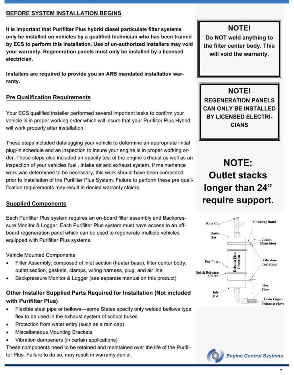
6 COMPONENT DESCRIPTION Vehicle Mounted Assembly The vehicle mounted filter assembly consists of an inlet section containing the electrical heating elements, a catalyzed DPF centerbody and an outlet section. 1. Inlet Section / Heater Base The inlet section contains the heater elements, (figure 9) that when powered combust the soot in the filter center body during a process referred to as active regeneration. Varieties of inlet configurations are available to facilitate vehicle fit. Figure 8 Vehicle Mounted Assembly 2. Catalyzed DPF Center Body Purifilter Plus utilizes a catalyzed silicon carbide wallflow diesel particulate filter. This is the same DPF centerbody employed in the Purifilter H. The filter center body is sized to afford reasonable exhaust restriction and sufficient surface area for the catalyst to oxidize the collected particulate. 3. Outlet Section A wide variety of outlet section configurations are available to provide a suitable fit for most vehicles. The outlet must be protected from water entry by the use of a rain cap. 4. Backpressure Monitor & Logger A Backpressure Monitor & Logger tracks the operation of the Purifilter Plus Hybrid unit and transmit signals to a small dash mounted readout (figure 11). This Backpressure Monitor stores relevant operational data and provides a visual indication as to when the Purifilter Plus Hybrid unit requires active regeneration. The dash display unit is provided with a wiring harness, required fittings and CD software disk. Please refer to the Backpressure Monitor & Logger manual for more details. 4. Regeneration Control Panel Wall Mounted Assembly The regeneration control panel (figure 12) houses the power and air supply to the heater elements. When connected to the regeneration control panel, active regeneration can be performed.. Figure 11 Backpuressure Monitor & Logger 6

7
8 Installation Instructions: Filter Assembly on Vehicle The Purifilter Plus is designed to replace the existing vehicle silencer. Installation position of the filter should be as close to the exhaust manifold as possible, normally where existing silencer is located. The following generic instructions are provided as basic information to purchasers of the Purifilter Plus. Purifilter Plus installations should only be performed by Engine Control Systems approved and trained technicians who will provide a separate installation warranty. 1. Avoid unnecessary and sharp pipe bends, diameter reductions, etc., that may increase exhaust backpressure. The diameter of the outlet pipe must be at least that of the outlet flange. The outlet must be protected from water entry. The Purifilter Plus vehicle assembly is heavier than standard silencers therefore the mounting support brackets should be able to withstand the increased weight. 2. Mount the Purifilter Plus on the chassis with supplied brackets or other suitable brackets and vibration dampers where indicated. 3. A minimum 24 length of flexible piping or bellows pipe should be installed between the turbocharger outlet and the inlet of the Purifilter Plus. This flex or bellows pipe shall yield about a 20% stretch from fully compressed to fully stretched. 4. Purifilter Plus vehicle assemblies should be mounted away from flammables. Please keep all flammables such as fuels, grease, oil, plastics, wiring harness, and rubbers away from the Purifilter Plus. Leaks in the area of the vehicle assembly should be repaired immediately. 4. Secure the wiring and air hose are away from moving parts and heat sources. The inlet base gets extremely hot when regenerating; a shield or additional insulation may be required on some installs to protect adjacent vehicle components which are susceptible to damage from heat (i.e. hydraulic lines, wiring, plastic, etc.). 5. Mount the electrical plug of the junction box and air hose of the heater base securely where accessible for frequent plug - in to avoid movement and interfering with other components. Ideally, these components will be installed behind an access door protecting these components from direct collision, water and road spray. 6. Before connecting the exhaust inlet pipe to the base heater, make sure the Back Pressure fittings are installed and welded on the inlet pipe for the Back Pressure monitor & Logger. Please see the Back Pressure Monitor and Logger Manual for installation instructions. The BP fittings are included in the Back Pressure Monitor Logger Kit. 7. Install the BP Monitor and Logger following the instructions contained within the separate manual. It is critically important that the remote readout display be mounted in a location visible to the driver so that LED indicator lights can be observed and reported. There are two indicator lights that specifically indicate the need to schedule or perform regeneration immediately. NOTE! Vehicle Installs should be performed by ECS AP- PROVED & TRAINED TECHNICIANS NOTE! Opacity test should be done before installation and recorded! NOTE! CJ4 Engine Oil is a low ash oil and is highly recommended as it will reduce your maintenance needs and cost NOTE! Do not weld anything to the to the filter center body. This will void the warranty. NOTE! Do not weld on the vehicle without disconnecting BP Monitor Logger power and vehicle battery. 8
9 REGENERATION CONTROL PANEL INSTALLATION NOTE! A certified electrician and ECS qualified technician MUST install product Only a licensed electrician should install the control panel on the wall or other suitable surface where the required power is available and where vehicle can be parked and plugged in. The panel should be away from combustible material. There are 4 holes on the back of the control panel for mounting purposes. The panel should be installed in a dry, covered area and not directly exposed to sun or precipitation. This can be done by installing the panel inside of a building and running the connection cables outside, or by installing the panel outside contained in a weather tight cabinet, or installed outside but under a dry covered area. Alternatively, the panel can also be connected to a cart to allow it to be wheeled up to the side of the vehicle. This option works well on sites where space is limited and access to a stationary fixed panel may not be possible. Only a licensed electrician only should connect to the available power supply using the electrical schematic provided with each panel to make the required connections. Scheduling and Tracking Vehicle Plug-in It is strongly recommended that a proactive vehicle plug-in schedule be implemented for every fleet vehicle equipped with a Purifilter Plus. This can be as simple as using a calendar with vehicle identification numbers scheduled on appropriate dates. Reactive plug-in should occur when the Backpressure Monitor Remote Readout LED s indicate Yellow (schedule regeneration within 48 hrs) or Red (plug-in vehicle that same day) alarms occur. It is also strongly recommended that plug-in logs be maintained at the regeneration control panel to confirm that scheduled vehicle plug-ins occur when scheduled. A regeneration log is the quickest way to track whether vehicle plug-in is occurring. A sample log sheet is included on page 18 of this manual. The Backpressure Monitor & Logger system on-board a vehicle can also be readily downloaded to confirm that regular plug-in are occurring. 9
10 HEALTH AND SAFETY PRACTICES Installing and maintaining the Purifilter Plus Hybrid safely It is the responsibility of the operator to ensure that persons involved in the installation and maintenance of the Purifilter Plus hybrid diesel particulate filter systems are aware of heavy lifting hazards and best practice lifting techniques. The Purifilter Plus can range in weight from 20lbs to over 80lbs. ECS manufacturers the CombiClean (DPF cleaning station). This equipment is available to efficiently perform the safe removal and collection of ash and unburned soot in a controlled environment. Attempting to service a Purifilter Plus centerbody with compressed shop air without the use of a Regeneration Control Panel or Combi- Clean station is strongly discouraged and is not an acceptable way to remove ash from the centerbody. See the troubleshooting section of this manual for more information on dealing with plugged filter centerbodies. Appropriate safety precautions such as a facemask and protective clothing, should be adhered to when dealing with the debris produced by the Purifilter Plus. The dust removed should be treated as similar to vehicle brake dust and considered hazardous if inhaled. Waste materials collected from servicing a Purifilter Plus should be disposed of in accordance with local regulations. 10


11 KNOWING WHEN TO REGENERATE The Purifilter Plus hybrid diesel particulate filter system can be proactively or reactively regenerated. It is strongly recommended that as a starting point, fleets follow the proactive regeneration recommendation determined by datalogging prior to system installation. After an initial period of operation, the BP Monitor Logger can be downloaded and the data used to revise the initial proactive regeneration period. Employing a proactive regeneration strategy minimizes disruptions to normal vehicle operation. It is recommended that proactive regeneration be performed immediately after vehicle shut down when the exhaust system is still hot. If regeneration is being performed in a response to a Yellow or Red alarm condition, the regeneration should be performed immediately upon engine shut down with the exhaust in a hot condition to promote a thorough regeneration. The Purifilter Plus is also continuously monitored by the BP Monitor & Logger and this information is routed to the remote readout unit which is positioned in a visible location to the vehicle operator. Figure. The BP Monitor & Logger Unit Your BP Monitor & Logger The Purifilter Plus Hybrid is designed to alert the operator when regeneration is required. Every system is equipped with a BP monitor which, has logging capabilities and the following warning lights; POWER: This Green LED is used to indicate that the BP Monitor & Logger unit is powered properly. If this light is not illuminated, service of the BP monitor & logger is required. SCHEDULE DPF SERVICE: When flashing continuously for more than 45 seconds during vehicle operation, this Yellow LED indicates that the DPF regeneration needs to be scheduled and should be performed within the next two days. Figure. Remote Driver Display (should be mounted in a location readily visible to the vehicle or equipment operator) SERVICE DPF NOW: When flashing for more than 45 seconds continuously, this Red LED indicates that DPF regeneration is needed as soon as possible and at longest by the end of that day. At this point, it is critical to perform regeneration as if this warning is ignored too much soot build up and as a result require additional servicing of the Purifilter Plus system or BP Monitor & Logger System. SYSTEM ERROR: When illuminated, this LED indicates that an internal wiring or connection fault exists within the BP Monitor & Logger System and maintenance is required. Please refer to the Regeneration Control Panel Schematic and the active regeneration instructions on the following pages for step by step instructions as to how to regenerate the Purifilter Plus System. 11
12 Control Panel Schematic A wiring diagram is included with every Control Panel. It is essential to retain this schematic as it will allow any licensed electrician to install the panel and assist with troubleshooting should problems arise. 1. Ammeter 1 depicting power usage by the first bank of heating elements 2. Ammeter 2 depicting the power usage by the second bank of heating elements 3. Ammeter 3 Depicting power usage by the third bank of heating elements (480 V models only) 4. Timer counts down time remaining until the regeneration process is complete 5. Green Light Illuminated when regeneration is complete 6. Orange Light Illuminated when regeneration is in progress 7. Red Light Illuminated if there is low air pressure detected. When this light is on, the power to the heater base is disconnected. Regeneration will not occur. 8. Temperature Controller Depicting current internal temperature of filter center body 9. Main ON/OFF Switch Initiates the regeneration process 10. Control Panel Lock Out When the Main switch is turned ON, the panel door cannot be opened 11. Control Panel Color the control panel is OSHA safety blue to warn of possible danger 12. Mounting Hole There are 4 holes for mounting purposes Control Panel 75 lbs. 12


13 REGENERATION INSTRUCTIONS NOTE! The Purifilter Plus must not be covered with any combustibles such as grease oil or any flammable material NOTE! Regeneration is best performed immediately upon engine shut down. The filter regeneration process must be completed without interruption! 1. Park the vehicle beside the regeneration panel closely enough that the power and air connections can be made. 2. Make sure the vehicle engine is turned off. 3. Identify the air line coupling and electric coupling located on the vehicle and connect the air and electric lines from the control panel. When the connections are made, the starter disable switch will prevent the vehicle from being started. 4. Some regeneration panels may require that a separate transformer be turned on first to supply the correct voltage to the control panel. Follow the steps required to turn on this transformer if one exists. 5. Check to see if a panel disconnect switch is present and if so, that it is ON. 6. On the Purifilter Plus Hybrid Control Panel, turn Main switch (9) to ON (see page 14 for control panel schematic). This will activate the air blowers and heater elements. 7. The regeneration in progress light (6) will be illuminated. 8. Check that the ammeters (1), (2) and (3) show an equal current draw. (If troubleshooting a problem, the actual current values can be found on the electrical drawing provided with panel) V Systems: SCP10 thru SCP23- The heating process will take 150 minutes. The digital counter (4) will count down 150 minutes. SCP28 The heating process will take 240 minutes 240 V Systems: The heating process will take 240 minutes. The digital counter (4) will count down 240 minutes. Figure. Identifying the air line (left) and electrical (right) connections. 10. When regeneration is complete. The ammeters (1), (2) and (3) will show 0, and the digital timer (4) will show 0, and the regeneration complete green light (5) will be illuminated. The LOW AIR PRES- SURE red light will also be illuminated. 11.Turn the Main switch (9) to OFF. 12. Disconnect the air and electric couplings. Wrap them upon their holding hook. The vehicle can now be started and is ready for use. ACTIVE REGENERATION RECORD KEEPING Figure. Vehicle Plugged in for regeneration ECS recommends that records be kept of vehicle plug-in for active regeneration. A sample log sheet is provided on page 19 which can be photocopied or used as a template. Keeping a log at the location of the regeneration panel will assist fleets to quickly check that vehicles are being proactively plugged-in at prescribed times. 13
14 MISSED A REGENERATION? WHAT TO DO? When a scheduled regeneration is missed, the BP Monitor Remote Readout should be checked for active alarms. This can be done by driving the vehicle and observing if any alarms are present or by downloading the data from the BP Monitor & Logger. If you drive the vehicle. If when the vehicle is driven no Yellow or Red alarms occur simply schedule the vehicle for plug-in at the next convenient time. If when the vehicle is driven the Yellow Alarm LED flashes continuously for more the 45 seconds (A YELLOW ALARM EVENT), plug-in the vehicle to the regeneration control panel and perform an active regeneration within the next 24 hours. If when the vehicle is driven a Red Alarm LED flashes continuously for more the 45 seconds (A RED ALARM EVENT), plug-in the vehicle to the regeneration control panel immediately and perform an active regeneration immediately. If after regeneration, either any Yellow or Red alarms persist, the BP Monitor & Logger should be downloaded. Read the next section for instructions what to do with the datalogger download. If you download the BP Monitor & Datalogger.. If the BP Monitor Logger has been downloaded, examine the histograms to determine if any Yellow or Red alarms are present. See the BP Monitor & Logger Manual for instructions how to perform this. If no Yellow or Red alarms are present, schedule the vehicle for plug-in at the next convenient time. If Yellow alarms are present, schedule the vehicle for plug-in within the next 24 hours. If Red alarms are present for no more than two days, plug-in the vehicle and perform regeneration immediately. This should return the filter to a clean condition. If Red alarms were present for more than two days, plug the vehicle in immediately and perform two back to back regenerations. If Red alarms are present in the downloaded histograms for more than two days, perform two back to back regenerations. If the vehicle when driven still presents Red alarms, the filter should be removed and cleaned on a Combiclean cleaning machine and returned to a clean condition. In this event, the BP Monitor & Logger water trap and BP sensor line should also be cleaned as an extended Red alarm event can cause this line to become fouled. If you still have trouble, move to the Troubleshooting Section. 14
15 MAINTENANCE Purifilter Plus maintenance records should be maintained to monitor and insure performance. Records should always be updated at each service interval and with every test. Regular preventative maintenance as described below will insure performance and vehicle up-time. Record keeping will also help predict issues before problems arise and protect your warranty. The following maintenance items should be preformed: At every oil change; 1. Check the BP Monitor & Logger and insure its proper operation. See BP Monitor & Logger Manual for specific instructions. 2. Inspect and clean if necessary, the water trap and its filter and line in the BP Monitor & Logger system. See BP Monitor & Logger Manual for specific instructions. 3. General inspection of installation hardware, electrical and air lines. 4. If the Purifilter Plus Hybrid filter assembly is installed in the vicinity of vehicle components which may develop oil, fuel, brake, transmission or power steering or hydraulic fluid leaks, inspect for the presence of any leaks and repair leaks immediately if any are found. At every filter de-ashing; De-ashing should be performed at the intervals listed in the Table on page 16. Maintenance records should be kept listing vehicle identification, vehicle mileage, and dates. These records should also list the following performed service items: 1. Service items performed at every oil change listed above. 2. Perform data download from BP Monitor & Logger. Review data for any change in vehicle duty cycle, or any existing fault within system. Confirmation of pro-active plug-in period. 3. Backpressure Measurement before and after filter de-ashing. Measurements to be performed at idle and rated speed/no load. 4. Engine Out Smoke opacity measurement at idle and rated speed / no load if opacity is excessive, other engine maintenance needs to be performed to reduce opacity to previously recorded value. 5. Filter observations from inspection. 6. Inspection of installation components and repair of any defects found. 7. Install new sealing gaskets. 15
16 ASH REMOVAL Although the regeneration process burns the collected soot, it leaves traces of residual ash. Ash is derived from lube oil and other wear metals that do not combust. Ash accumulates within the filter and needs to be removed periodically. The use of a low ash lubricant meeting a CJ-4 standard is highly recommended and will extend the interval between ash cleaning and reduce your maintenance cost. If engine performance is not maintained, the filter may be required to be removed and cleaned more frequently resulting in more downtime which can be costly. Perform Ash removal at intervals prescribed in the table below. Most vehicles will only require de-ashing once a year. Vehicle Type Engine Hours Miles Yearly Urban Buses & Solid Waste Fleets ,000 to 30, / yr School Buses 1 / yr Municipal & Short Haul Delivery Fleets ,000 1 / yr Long Haul ,000 1 / yr Table. Filter De-ashing intervals. Prior to ash removal, perform the following: 1. Regenerate the filter body on the vehicle. 2. Let the filter body cool down 3. Use the ECS CombiClean filter cleaning station to remove ash from the filter. 4. Prior to re-installing the filter to the vehicle, perform opacity tests and perform any indicated engine maintenance. 5. RECORD ENGINE HOURS, VEHICLE MILEAGE, FILTER AND installation inspection and record comments on the record sheets provided or into your vehicle maintenance logs. 6. Perform scheduled maintenance of Purifilter Plus system and BP Monitor & Logger. Alternatively, contact your local ECS Distributor who will perform this process for you for a fee. Waste Disposal Ash removed during the cleaning process should be disposed of in accordance with all applicable Federal, State and local laws governing waste disposal. 16

17 CONTAMINATED FILTERS If a Purifilter is contaminated with oil, coolant or diesel fuel, remove IMMEDIATELY and do not use. Contact ECS or an authorized ECS dealer for further information. DO NOT attempt to clean an oil, coolant or diesel-laden filter on any cleaning machine. Contact ECS for further instruction. DO NOT WASH A PURIFILTER WITH: - GASOLINE OR OTHER SOLVENTS - DIESEL FUEL - STEAM - HIGH PRESSURE WATER - WATER OPERATE IN THE CORRECT FLOW DIRECTION AS INDICATED ON THE FILTER CENTER BODY DO NOT USE COMPRESSED AIR ON A HOT FILTER Use caution when working near a hot filter, especially after vehicle use. Please follow proper lifting techniques when handling a filter. Use approved techniques and equipment when cleaning a filter. 20
18 General Troubleshooting 1. Frequent Yellow or Red Alarms prior to scheduled proactive plug-in Perform the following; Download the BP Monitor & Logger to determine whether scheduled regenerations have been missed. If so, perform a back to back regeneration to see if problems is resolved. During regeneration insure there are no faults shown by the regeneration control panel. If the regeneration is not occuring properly, troubleshoot the vehicle installation or control panel depending upon the fault being revealed during regeneration. Download the datalogger and evaluate whether a change in exhaust temperature or a trend in backpressure is apparent. If the duty cycle has changed, discuss with your ECS distributor what adjustment may be necessary. If your fleet operates in an area where seasonal changes are dramatic you may need to employ different plug-in schedules to offset seasonal changes. Example: Many fleets may require more frequent plug-ins during the winter months. If the datalogger download appears normal, remove the filter centerbody and perform an engine-out opacity test to confirm the condition of the engine. If opacity has increased from the value reported at the time of installation, inspect the engine air filter, intake air system for leaks, turbocharger problems injectors & pump, or if oil consumption is excessive - do a compression test. Opacity issues must be corrected prior to re-installation of the Purifilter Plus centerbody. 2. Loss of engine power with no alarms Perform the following; Download the BP monitor and logger and examine whether backpressure is being recorded. If there is no BP data (all zeros), service the backpressure sensor line insuring lines are clean, water trap is clean. If problem is still present, the fault is internal to the BP monitor and logger call you ECS Distributor for service. DO NOT OPEN THE BP MONITOR LOGGER BOX OR WARRANTY WILL MAY BE VOIDED. Using a manometer, measure the backpressure restriction across the filter centerbody. If excessive, remove the filter centerbody for inspection. If the filter is plugged, clean the filter centerbody on a Combiclean cleaning station. Perform an engine out opacity test. Is the result consistent with initial opacity recorded at time of installation. If it is higher than at the time of installation, inspect the engine air filter, intake air system for leaks, turbocharger problems injectors & pump, or if oil consumption is excessive - do a compression test. Opacity issues must be corrected prior to re-installation of the Purifilter Plus centerbody. 17
19 General Troubleshooting cont d 3. Loss of Engine Power with Red Alarm Perform the following; Remove vehicle from service immediately Download the BP Monitor & datalogger and determine the peak observed backpressure. If peak backpressure exceeds 350 mbar, remove the filter for cleaning using a Combiclean cleaning machine. If using a manometer, manually measure the backpressure between the engine and the Purifilter Plus Hybrid assembly. If peak backpressure exceeds 350 mbar, remove the filter for cleaning using a Combiclean cleaning machine. If visible signs of oil or diesel fuel are present, do not clean the filter. Contact your ECS distributor for support. If peak backpressure is >350 mbar, remove the Purifilter Plus centerbody, and measure engine out opacity. Inspect engine air filter, intake air system for leaks, turbocharger problems, injectors & pump, or if oil consumption is excessive - do a compression test. Opacity issues must be corrected prior to re-installation of the Purifilter Plus centerbody. If peak backpressure is <350 mbar, remove the Purifilter Plus centerbody, and measure engine out opacity. Inspect engine air filter, intake air system for leaks, turbocharger problems, injectors & pump, or if oil consumption is excessive - do a compression test. Opacity issues must be corrected prior to re-installation of the Purifilter Plus centerbody. If there are any visible signs of fuel or oil in the filter centerbody, do not clean the filter. Contact your ECS distributor for support. If there are no visible signs of fuel or oil in the filter centerbody, re-install the filter centerbody and perform back to back active regenerations prior to returning vehicle to service. 4. Visible signs of black smoke Perform the following; Remove the DPF centerbody for inspection. Contact ECS distributor for support. 5. Visible signs of white smoke White smoke is typically water vapor which will typically clear after a few minutes. If white smoke persists, inspect your engine for signs of coolant consumption. If there is a coolant leak, remove the filter and allow it to dry. Inspect the filter for signs of damage prior to re-installation. Call you ECS distributor for support. 6. Visible signs of blue smoke Blue smoke is typically indicates the presence of unburned fuel or engine oil. Blue smoke may be visible for the first few minutes after vehicle start. If blue smoke persists, remove the filter for inspection and correct underlying engine fault. 18
20 Regeneration Control Panel Trouble Shooting If the control panel is not operating correctly, have a licensed electrician check the following: 1. Electrical Heaters The ammeters on the regeneration control panel should display consistent ampere draws within the provided ranges below. All 240V Single Phase Systems: 14 to 17 amps 480V 3-Phase Systems: Filter Model / Type Amp. (at 480V) SCP10 thru SCP23 all 9 to 11 amps SCP28 17 to 21 amps If the ammeters do not indicate the above values, check the following: If all three ammeters report values below the ranges above or zero, check the power supply to the panel or power from contactor within the panel. If one of the ammeters reports a low or zero value, this typically indicates an element has failed within the heat base in the DPF inlet section on the vehicle. If no signs of power in the panel are present, check power supply from disconnect switch and fuses related to that switch. Is the regeneration in process light illuminated?. If illuminated, problem is within the panel, call licensed electrician or ECS distributor. The fuses are OK Check if the low air pressure light is On. If so, there is a problem with the air pump or pressure switch. The regeneration unit is connected according to the circuit diagram. Correct circuit diagram number is shown in the installation instructions included with the panel. If After checking the above conditions, if the ampere draw is still insufficient, check functionality of inlet heater base on vehicle. 2. Temperature Control ((8) on Panel Schematic page 13) The thermostat is set at C for all systems. This temperature should be reached after 10 minutes or the start of the regeneration cycle. Upon reaching the set temperature, the thermostat will maintain the temperature by regularly cycling the heaters. Make sure the ammeters indicate that this is the case by visually checking the movement of the pointer. If this temperature is not being reached, contact your local ECS distributor. 4. Air Supply ((7) on Panel Schematic page 13) The amount of air supplied to the filter center body is critical to regeneration. If this light illumates, check air pressure switch or pump. Make sure the connection between the vehicle and panel is secure and without leaks. Insure that the original parts have not been replaced with other types (different diameters, flow restriction, etc.). Contact ECS local distributor for support. 19
21 20
22 RECORDS Items Please Fill Out Date and Engine Hours Vehicle Odometer miles/km Vehicle Registration Purifilter Serial Number Idle Backpressure Purifilter Cleaning Notes (ie. Visual condition ) Items Please Fill Out Date and Engine Hours Vehicle Odometer miles/km Vehicle Registration Purifilter Serial Number Idle Backpressure Purifilter Cleaning Notes (ie. Visual condition ) Signed Items Please Fill Out Date and Engine Hours Vehicle Odometer miles/km Vehicle Registration Purifilter Serial Number Idle Backpressure Purifilter Cleaning Notes (ie. Visual condition ) Signed Sample forms 21
23 WARRANTY RIGHTS AND OBLIGATIONS For Purifilter Plus Units sold for On-road applications Sold by Engine Control Systems Limited/Ltd. Engine Control Systems Limited and Engine Control Systems Ltd. (hereafter referred to as ECS ) must warrant the diesel emission control system in the application for which it is sold or leased to be free from defects in design, materials, workmanship, or operation of the diesel emission control system which cause the diesel emission control system to fail to conform to the emission control performance level it was verified to, or to the requirements in the California Code of Regulations, Title 13, Sections 2700 to 2706, and 2710, for the periods of time listed below, provided there has been no abuse, neglect, or improper maintenance of your diesel emission control system, vehicle or equipment, as specified in the owner s manuals. Where a warrantable condition exists, this warranty also covers the engine from damage caused by the diesel emission control system, subject to the same exclusions for abuse, neglect or improper maintenance of your vehicle or equipment. Please review your owner s manual for other warranty information. Your diesel emission control system may include a core part (e.g., particulate filter) as well as hoses, connectors, a back pressure monitor, and other emission related assemblies. Where a warrantable condition exists, ECS will repair or replace your diesel emission control system at no cost to you including diagnosis, parts, and labor. WARRANTY COVERAGE For on-road applications; For vehicles with GVWR of at least 33,000 lbs. the warranty shall be 2 year, unlimited miles if the truck; - is typically driven over 100,000 miles per year, and - has less than 300,000 miles on the odometer at the time of installation For vehicles with GVWR of at least 19,500 lbs. and engines rated above 250 hp-5 years or 150,000 miles whichever comes first For vehicles with GVWR of at least 19,500 lbs. and engines rated 250hp and lower 5 years or 100,000 miles whichever comes first For vehicles with GVWR or less than 19,500 lbs. 5 years or 60,000 miles, whichever comes first If any emission-related part of your diesel emission control system is defective in design, materials, workmanship, or operation of the diesel emission control system thus causing the diesel emission control system to fail to conform to the emission control performance level it was verified to, or to the requirements in the California Code of Regulations, Title 13, Sections 2700 to 2706, and 2710, within the warranty period, as defined above, ECS will repair or replace the diesel emission control system, including parts and labor. In addition, ECS will replace or repair the engine components to the condition they were in prior to the failure, including parts and labor, for damage to the engine proximately caused by the verified diesel emission control strategy. This also includes those relevant diagnostic expenses in the case in which a warranty claim is valid. ECS may, at its option, instead pay the fair market value of the engine prior to the time the failure occurs. OWNER S WARRANTY RESPONSIBILITY As the vehicle owner, you are responsible for performing the required maintenance described in your owner s manual. ECS recommends that you retain all maintenance records and receipts for maintenance expenses for your vehicle, engine, or equipment, and diesel emission control system. If you do not keep your receipts or fail to perform all scheduled maintenance, ECS may have grounds to deny warranty coverage. You are responsible for presenting your vehicle, equipment, or engine, and diesel emission control system to an ECS dealer as soon as a problem is detected. The warranty repair or replacement should be completed in a reasonable amount of time, not to exceed 30 days. If a replacement is needed, this may be extended to 90 days should a replacement not be available, but must be performed as soon as a replacement becomes available. If you have questions regarding your warranty rights and responsibilities, you should contact ECS at or the California Air Resources Board at 9528 Telstar Avenue, El Monte, California 91731, or (800) , or electronic mail: helpline@arb.ca.gov. 22
24 Installation Warranty Statement The installation of your Purifilter Plus hybrid diesel particulate filter system is covered by a separate warranty as mandated by ARB regulations. The installer of your Purifilter Plus in most cases will be an authorized ECS distributor or under contract to an authorized ECS distributor. As per ARB regulations, the installer of a verified emissions control device must furnish the owner with a copy of the following statement. YOUR WARRANTY RIGHTS AND OBLIGATIONS (Installer s name) must warrant that the installation of a diesel emission control system is free from defects in workmanship or materials which cause the diesel emission control system to fail to conform to the emission control performance level it was verified to, or to the requirements in the California Code of Regulations, Title 13, Sections 2700 to The warranty period and the extent of the warranty coverage provided by (installer s name) must be the same as the warranty provided by the product manufacturer, and the same exclusions apply. OWNER S WARRANTY RESPONSIBILITY As the vehicle, engine or equipment owner, you are responsible for presenting your vehicle, engine, or equipment and diesel emission control system to (installer s name) as soon as a problem with the installation is detected. If you have questions regarding your warranty rights and responsibilities, you should contact (installer s contact information) at XXX-XXXX or the Calilfornia Air Resources Board at 9528 Telstar Avenue, El Monte, California, 91731, or , or electronic mail: helpline@arb.ca.gov. 23
25 Glossary of Terms Active Regeneration when soot is oxidized and reduced to ash within the filter and the oxidation process is initiated by an outside source (such as electricity) Ash the residue that is left after soot and other elements have been oxidized or combusted AZ Catalyst improves reductions of HC, CO and PM. Can be housed in the outlet section Backpressure the pressure is an exhaust system caused by pipe bends, silencers or other restrictions to exhaust flow Backpressure Monitor a signal lamp to ware the driver of increased backpressure in the filter assembly detected by pressure switch mounted before the filter center body Balance Point The point at which the amount of soot being collected is equal to the amount of soot being oxidized Catalyst an entire device consisting of a filter, a precious metal coating and a surrounding shell. It is by definition, a compound, element or other substance that encourages a reaction to take place between two or more elements of compounds, without changing or becoming part of the reaction itself. In exhaust technology, a catalyst is generally a formulation of precious metals and/or base metals. Their function is normally to promote an oxidation process. Data Logger a small computer which is able to store signals from sensors against time Diesel Particulate Filter a filter which physically removes fine particulates from an exhaust stream can be referred to as a trap, filter, particulate trap, soot trap, soot filter, catalyzed trap or regenerative trap. Duty Cycle the normal type of duty that a vehicle performs at regular intervals. For example, a park and ride bus would have a very predictable route and short cycle frequency compared to a long distance haulage truck. Filter Assembly houses the inlet section, outlet section and filter center body Filter Center Body made up of Silicon Carbide, the filter center body traps the particulate matter from the exhaust and stores it as soot until regeneration Inlet Section takes in exhaust from the vehicle Outlet Section passes clean exhaust, which can either house the AZ catalyst or not Particulate this is any form of fine dust, however particulate has become the term for diesel engine derived soot or dust less than 10 microns in diameter. Passive Regeneration when soot is oxidized and reduced to ash within the filter, the filter is undergoing an automatic process that bring its condition close to optimum. Regeneration when soot is oxidized and reduced to ash within the filter, the filter is undergoing an automatic process that brings its condition close to optimum Thermocouple is a device that converts temperature to an electrical output. This output can be interpreted and stored by a small computer 24

26 Contact Information Engine Control Systems Limited World Headquarters 83 Commerce Valley Drive East Thornhill, Ontario, L3T 7T3 Phone: Toll Free: Fax: Engine Control Systems Ltd. North America Western 4910 Longley Lane, Suite 103 Reno, Nevada, Phone: Fax: Engine Control Systems Europe AB European Headquarters Box 9015, Agnesfridsvagen, 184 SE Malmo, Sweden Phone: 46 (40) Fax: 46 (40) Website:
27 Labels for New York State: M (Affix to a visible location such as a door jamb or firewall) The attached label is to be affixed to a visible location such as a door jamb or firewall) upon installation of an ECS Purifilter Plus and Purifilter to comply with Part 248 of 6 NYCRR, entitled Use of Ultra Low Sulfur Diesel Fuel and Best Available Retrofit Technology for Heavy Duty Vehicles (BART). The label should be affixed in an easily visible location which is clean and free from grease, oil or loose paint. This label should not cover any part of other engine labels which are present for engine manufacturer regulatory requirements. Additionally, it is the installer s responsibility to legibly transfer the information needed to the spaces provided on the label using a permanent pen and remove the backing to seal the label. Failure to perform these steps may result in enforcement penalty. When installed, there is an image of the label beneath for confirmation and future reference. Engine Control Systems assumes no liability. Protective Coat Engine Label
GreenTRAP Diesel Particulate Filter
 Nett Technologies Inc. 2-6707 Goreway Drive, Mississauga, Ontario Canada L4V 1P7 tel: 905.672.5453 fax: 905.672.5949 e-mail: sales@nett.ca web: http://www.nett.ca GreenTRAP Diesel Particulate Filter V1.3
Owners Manual: Flow Through Filter (FTF) System
 System") PROVENTIA EMISSION CONTROL carb-verified, level 2+ tru Filter RETROFIT Owners Manual: Flow Through Filter (FTF) System Including Installation Guide for Sentry Model TRUs Proventia Americas, LLC c/o Proventia
PROVENTIA EMISSION CONTROL carb-verified, level 2+ tru Filter RETROFIT Owners Manual: Flow Through Filter (FTF) System Including Installation Guide for Sentry Model TRUs Proventia Americas, LLC c/o Proventia
Owners Manual: Flow Through Filter (FTF) System
 System") PROVENTIA EMISSION CONTROL carb-verified, level 2+ tru Filter RETROFIT Owners Manual: Flow Through Filter (FTF) System Including Installation Guide for SB Model TRUs Proventia Americas, LLC c/o Proventia
PROVENTIA EMISSION CONTROL carb-verified, level 2+ tru Filter RETROFIT Owners Manual: Flow Through Filter (FTF) System Including Installation Guide for SB Model TRUs Proventia Americas, LLC c/o Proventia
CARB VERIFIED DIESEL PARTICULATE FILTER OWNER S MANUAL
 CARB VERIFIED DIESEL PARTICULATE FILTER OWNER S MANUAL Ref. # OM0020908 pg. 1 OWNER S MANUAL State of California Warranty Information........................ 3 Product Description.............................................
LongMile -S. Owner s Manual
 LongMile -S Owner s Manual The instructions, specifications, and recommendations in this manual are based on current information when this manual was released. ESW CleanTech, Inc. reserves the right to
EMISSION WARRANTIES FOR MTU ON-HIGHWAY APPLICATIONS
 2017 EMISSION WARRANTIES FOR MTU ON-HIGHWAY APPLICATIONS Page 1 of 7 1 FEDERAL EMISSION CONTROL WARRANTY STATEMENT 1.1 Emissions Warranty MTU America Inc. (MTU) warrants to the owner ( Owner ) of engines
Your Warranty Rights and Obligations (Applies Only to Vehicles Certified for Sale and Registered in the State of California)
") Your Warranty Rights and Obligations (Applies Only to Vehicles Certified for Sale and Registered in the State of California) The California Air Resources Board is pleased to explain the emission control
Your Warranty Rights and Obligations (Applies Only to Vehicles Certified for Sale and Registered in the State of California) The California Air Resources Board is pleased to explain the emission control
Unikat Combifilter. Diesel Particulate Filters (DPF) Fork lift trucks Wheel loaders Generator sets Mining vehicles Railway engines
 Fork lift trucks Wheel loaders Generator sets Mining vehicles Railway engines") Unikat ombifilter Diesel Particulate Filters (DPF) Fork lift trucks Wheel loaders Generator sets Mining vehicles Railway engines Function The Unikat ombifilter is an integrated diesel particulate filter
Unikat ombifilter Diesel Particulate Filters (DPF) Fork lift trucks Wheel loaders Generator sets Mining vehicles Railway engines Function The Unikat ombifilter is an integrated diesel particulate filter
D28 V12 US Tier 2 / 3. Emission Warranty Off Road / Non Road Engines. MAN Engines
 D28 V12 US Tier 2 / 3 Emission Warranty Off Road / Non Road Engines MAN Engines Contents Introduction Emission Warranty.... 3 Emission Control System Warranty Statement Your Warranty Rights and Obligations...
Inspection of Vehicles Equipped with 2007 or Later EPA-Certified Engines
 Summary Created: Nov. 19, 2008 Revised: May 19, 2010 Revised: April 27, 2017 This Inspection Bulletin explains how to safely inspect motorcoaches, buses, trucks and truck tractors equipped with 2007 or
Emission Control System Warranty Statement
 Emission Control System Warranty Statement Marine and industrial diesel engines Supplement to Operator s Manual (USA) Marine engines This Emission Control System Warranty Statement applies only to engines
Owner s Manual Supplement. Liquefied Petroleum Gas (LPG) Fuel System for 1998 GM Medium Duty Chassis (C-60/C-70) with 6.0L and 7.
 Fuel System for 1998 GM Medium Duty Chassis (C-60/C-70) with 6.0L and 7.") Owner s Manual Supplement Liquefied Petroleum Gas (LPG) Fuel System for 1998 GM Medium Duty Chassis (C-60/C-70) with 6.0L and 7.0L V8 OWNERS MANUAL SUPPLEMENT Table of Contents Refueling Your Vehicle...1
Owner s Manual Supplement Liquefied Petroleum Gas (LPG) Fuel System for 1998 GM Medium Duty Chassis (C-60/C-70) with 6.0L and 7.0L V8 OWNERS MANUAL SUPPLEMENT Table of Contents Refueling Your Vehicle...1
Your Warranty Rights and Obligations
 Your Warranty Rights and Obligations (Applies Only to Vehicles Certified for Sale and Registered in the State of California) 6.7L Diesel Engine Medium Duty Trucks Products Warranted This Emission Control
Exhaust After-Treatment System. This information covers design and function of the Exhaust After-Treatment System (EATS) on the Volvo D16F engine.
 on the Volvo D16F engine.") Volvo Trucks North America Greensboro, NC USA DService Bulletin Trucks Date Group No. Page 1.2007 258 44 1(6) Exhaust After-Treatment System Design and Function D16F Exhaust After-Treatment System W2005772
Volvo Trucks North America Greensboro, NC USA DService Bulletin Trucks Date Group No. Page 1.2007 258 44 1(6) Exhaust After-Treatment System Design and Function D16F Exhaust After-Treatment System W2005772
Nelson Global Products, Inc. Diesel Particulate Filter (DPF) and Diesel Oxidation Catalyst (DOC)
 and Diesel Oxidation Catalyst (DOC)") Nelson Global Products, Inc. Diesel Particulate Filter (DPF) and Diesel Oxidation Catalyst (DOC) Installation, Operation and Maintenance Guide *NOTE: USA 49-State Legal NOT Legal for State of California
Nelson Global Products, Inc. Diesel Particulate Filter (DPF) and Diesel Oxidation Catalyst (DOC) Installation, Operation and Maintenance Guide *NOTE: USA 49-State Legal NOT Legal for State of California
Presented by. Navistar Education 2015
 Presented by Navistar Education 2015 1.2 Overview This course is intended to provide parts specialists with a description of Diesel Exhaust Fluid, or DEF, part number configuration, ordering and distribution
Additions, Revisions, or Updates
 4 68-12 1 4 68-12 SUBJECT DATE SPN 5018/FMI 18 - GHG14 September 2012 Additions, Revisions, or Updates Publication Number / Title Platform Section Title Change DDC-SVC-MAN-0084 DD Platform SPN 5018/FMI
Reach ins, Freeezers & Refrigerators Installation & Operation Manual
 Reach ins, Freeezers & Refrigerators Installation & Operation Manual BSR23 BSF23 BSR49 BSF49 BSR72 BSF72 IMPORTANT SAFETY INSTRUCTIONS (SAVE THESE INSTRUCTIONS) Visit us on the web at www.blueairinc.com
2013 Aftertreatment System with SCR Overview for Technicians Study Guide
 TMT121340 Class Course Code: 8359 2013 Aftertreatment System with SCR Overview for Technicians Study Guide 2013 Aftertreatment System with SCR Study Guide 2013 Navistar, Inc. All rights reserved. All marks
Your Warranty Rights and Obligations (Applies Only to Vehicles Certified for Sale and Registered in the State of California)
") Your Warranty Rights and Obligations (Applies Only to Vehicles Certified for Sale and Registered in the State of California) The California Air Resources Board is pleased to explain the emission control
Your Warranty Rights and Obligations (Applies Only to Vehicles Certified for Sale and Registered in the State of California) The California Air Resources Board is pleased to explain the emission control
m b e E M I S S I O N S E N G I N E
 m b e 4 0 0 0 2 0 0 7 E M I S S I O N S E N G I N E We re DRIVING TECHNOLOGY. Detroit Diesel and Mercedes-Benz have over 150 combined years of experience designing, testing and manufacturing diesel engines.
Eminox Electronic Service Indicator
 ESI Installation and Instruction Manual Eminox Electronic Service Indicator I n s t a l l a t i o n a n d I n s t r u c t i o n M a n u a l LITM004 ESI Installation and Instruction Manual Section Title
messages displayed with extended idle operation
 Congratulations on selecting the new Super Duty with one of the most advanced pieces of automotive technology -- the new 6.4L Power Stroke diesel engine. The 6.4L Power Stroke delivers all the horsepower
2007 Emissions: Fundamentals
 A N AV I S TA R C O M PA N Y 2007 Emissions: Fundamentals Study Guide TMT-100718 Study Guide 2007 Emissions: Fundamentals TMT-100718 2007 International Truck and Engine Corporation 4201 Winfield Road,
Your Warranty Rights and Obligations (Applies Only to Vehicles Certified for Sale and Registered in the State of California)
") Your Warranty Rights and Obligations (Applies Only to Vehicles Certified for Sale and Registered in the State of California) The California Air Resources Board is pleased to explain the emission control
Your Warranty Rights and Obligations (Applies Only to Vehicles Certified for Sale and Registered in the State of California) The California Air Resources Board is pleased to explain the emission control
State of California AIR RESOURCES BOARD EXECUTIVE ORDER DE
 State of California AIR RESOURCES BOARD EXECUTIVE ORDER DE-09-005-05 The diesel emission control strategy described herein qualifies as a potential compliance option for the Air Resources Board's (ARB)
Driver Tips For Fire And Emergency Vehicles. For EPA 2013 Cummins On-Highway Heavy-Duty And MidRange Engines With Aftertreatment.
 Driver Tips For Fire And Emergency Vehicles. For EPA 2013 Cummins On-Highway Heavy-Duty And MidRange Engines With Aftertreatment. This guide covers engine, aftertreatment and emissions-related indicator
YAMAHA MOTOR CORPORATION, U.S.A. MZ-SERIES ENGINES 3-YEAR LIMITED WARRANTY
 Yamaha Motor Corporation, U.S.A., hereby warrants that new Yamaha MZ-series Spark Ignited Small Off Road Engines, hereafter called SORE engines, purchased from an authorized Yamaha SORE engine dealer in
Owner s Information Manual
 50ES---A and 50VL---C Comfort 13SEERThreePhase2½---5NominalTons (Sizes 30---60) Comfort 14 SEER Single and Three Phase 2---5 Nominal Tons (Sizes 24---60) Single Packaged Air Conditioner System With Puronr
Operator s Safety and Service Manual
 !! Operator s Safety and Service Manual Cordless Sprayer Model: C100WO SMK Industries Inc 12839 Carpenter Trail Carlisle. IA 50047 Phone: 515-202-0052 Email: john@smksprayers.com Web: www.smksprayers.com
Driver Tips. For Cummins On-Highway Heavy-Duty And MidRange Engines With Aftertreatment.
 Driver Tips. For Cummins On-Highway Heavy-Duty And MidRange Engines With Aftertreatment. This guide covers engine, aftertreatment and emissions-related indicator lamps* found on your vehicle s instrument
Before equipment use, please read this operation manual carefully. Serial Number: Date Purchased:
 Pushed & Geared Trolleys OPERATION MANUAL This operation manual is intended as an instruction manual for trained personnel who are in charge of installation, maintenance, repair etc. Before equipment use,
Additions, Revisions, or Updates
 1 9 04-11 SUBJECT DATE SPN 3250 / FMI 16 DOC Outlet Temperature High August 2011 Additions, Revisions, or Updates Publication Number / Title Platform Section Title Change DDC-SVC-MAN-0084 EPA07 DD13/DD15
CONTACT: Rasto Brezny Executive Director Manufacturers of Emission Controls Association 2200 Wilson Boulevard Suite 310 Arlington, VA Tel.
 WRITTEN COMMENTS OF THE MANUFACTURERS OF EMISSION CONTROLS ASSOCIATION ON CALIFORNIA AIR RESOURCES BOARD S PROPOSED AMENDMENTS TO CALIFORNIA EMISSION CONTROL SYSTEM WARRANTY REGULATIONS AND MAINTENANCE
OPERATING INSTRUCTIONS AND TROUBLE SHOOTING GUIDE
 OPERATING INSTRUCTIONS AND TROUBLE SHOOTING GUIDE Thank you for purchasing Driverite-Firestone Air Suspension System. You have purchased a quality product from the world s number one Air Spring Manufacturer.
MOVE TO ZERO. Setting new standards for performance and reliability with near-zero emissions.
 MOVE TO ZERO Setting new standards for performance and reliability with near-zero emissions. THE L9N. MOVE TO ZERO. Introducing the next generation of low-emission engine technology. The Cummins Westport
TC Series Cooling Systems
 TC Series Cooling Systems Table of Contents Table of Contents...1 List of Figures...1 Safety...2 Introduction...2 General Specifications...2 Types of Coolant...2 Routine Maintenance...2 Surge Tank Coolant
A2P Single Phase Automatic Industrial Battery Charger
 A2P Single Phase Automatic Industrial Battery Charger Featuring 205B Konrad Cres., Markham, ON, L3R 8T9 www.chargers.ca Building Canada s toughest battery chargers for over a century. Congratulations on
IMPORTANT INFORMATION ABOUT YOUR L TDI Volkswagen GENERATION 2.2 ENGINE
 IMPORTANT INFORMATION ABOUT YOUR 2015 2016 3.0L TDI Volkswagen GENERATION 2.2 ENGINE Contents About this Booklet... 1 Overview... 2 Software and Hardware Updates... 3 Changes in Maintenance Schedule...5
Active Controlled Cooling System
 Active Controlled Cooling System April 2011 3267 Progress Dr Orlando, FL 32826 www.apecor.com Preliminary www.apecor.com Table of Contents General Information... 3 Safety... 3 Introduction... 3 What s
IMPORTANT INFORMATION
 Volkswagen Canada P.O. Box 842, Stn. A Windsor, ON N9A 6P2 This notice applies to your vehicle: Subject: Emissions
Exhaust System - 2.2L Diesel
 Page 1 of 9 Published: Mar 8, 2007 Exhaust System - 2.2L Diesel COMPONENT LOCATION - WITH DIESEL PARTICULATE FILTER Item Part Number Description 1 Exhaust manifold (ref only) 2 Pressure differential sensor
OWNER S MANUAL SELF-PRIMING PORTABLE UTILITY PUMP
 Model 54011-0 OWNER S MANUAL SELF-PRIMING PORTABLE UTILITY PUMP Questions, problems, missing parts? Before returning to the store call AQUAPRO Customer Service 8 a.m. - 5 p.m., EST, Monday-Friday 1-844-242-2475
Blue Air. Commercial Refrigeration Inc. Installation & Operation Manual Chef Bases
 Blue Air Commercial Refrigeration Inc. Installation & Operation Manual Chef Bases Please read this manual completely before installing or operating this unit! BACB53 BACB71 BACB74 BACB83 BACB86 BACB96
TBE-700. Operation, Safety and Maintenance Manual. Stainless Steel Weld Cleaning System. Ensitech Pty Ltd
 Stainless Steel Weld Cleaning System Operation, Safety and Maintenance Manual TBE-700 TBE-700 Instruction Manual Oct 2013 (USA) FOREWORD FOREWORD This manual is a very important tool! Keep it with the
ADMINISTRATIVE GUIDE Revised February, 2010
 MOPAR 3-YEAR/100,000-MILE REMANUFACTURED POWERTRAIN PARTS WARRANTY ADMINISTRATIVE GUIDE Revised February, 2010 Mopar s 3-Year/100,000-Mile Remanufactured Powertrain Parts Warranty (3/100) available on
Warranty Information North America
 Publication No. 47705137 January 1, 2014 Warranty Information North America Industrial and Power Generation Power Systems Parts and Accessories Includes: Power Systems Warranty Statement Parts and Accessories
Subject: Emissions Recall 23V1 Approved Emissions Modification for Model Year Volkswagen Touareg 3.0L TDI
 August 2018 Volkswagen Canada P.O. Box 842, Stn. A Windsor, ON N9A 6P2 This notice applies to your vehicle: Subject: Emissions
ROTARY BRUSH CUTTERS THE LEADER OF THE PACK OWNER/OPERATOR SAFETY & INSTRUCTION MANUAL
 72 M-AX ROTARY BRUSH CUTTERS THE LEADER OF THE PACK OWNER/OPERATOR SAFETY & INSTRUCTION MANUAL CONTENTS Page 1. Introduction..................................2 2. Safety Instructions...........................3-4
Horizon. Owner s Manual. ATTENTION: Keep a copy of this Owner s Manual in the vehicle at all times.
 Horizon Owner s Manual ATTENTION: Keep a copy of this Owner s Manual in the vehicle at all times. The instructions, specifications, and recommendations in this manual are based on current information when
Blue Air. Commercial Refrigeration Inc. Installation & Operation Manual Glass Door Countertop Refrigerator
 Blue Air Commercial Refrigeration Inc. Installation & Operation Manual Glass Door Countertop Refrigerator Please read this manual completely before installing or operating this unit! BAGR7 Blue Air reserves
Model LA 4400 Time Delay OFF Controller
 ISIMET LA Series Model LA 4400 Time Delay OFF Controller Installation, Operation and Maintenance Manual Application: The Time Delay OFF Controller with integral 24-hr. programmable time clock operates
PREFACE. Dear customer,
 1 PREFACE Dear customer, Diesel exhaust particulate filters made by HUSS have been especially developed to enable the operation of diesel exhaust particulate filters even independently on current. The
Users Manual Certified Series Direct Drive Pump 1-7 LPM
 Users Manual Certified Series Direct Drive Pump 1-7 LPM Safety, Operating, Installation, and Maintenance Instructions 600 S 56 th Street #9 Chandler, AZ 85226 Phone: 480-507-6478 Fax: 480-838-2232 www.fogco.com
G8 Portable Fuel Transfer Pump Owner s Manual
 G8 Portable Fuel Transfer Pump Owner s Manual GENERAL INFORMATION This pump is designed for use only with gasoline (up to 15% alcohol blends such as E15), diesel fuel (up to 20% biodiesel blends such as
IMPORTANT INFORMATION ABOUT YOUR L TDI Volkswagen Passat Automatic Transmission. Voir le verso pour la version française.
 IMPORTANT INFORMATION ABOUT YOUR 2012 2014 2.0L TDI Volkswagen Passat Automatic Transmission Voir le verso pour la version française. Contents About This Booklet... 1 Overview... 2 Software Updates...
EMISSION WARRANTIES MS65022/02E
 EMISSION WARRANTIES MS65022/02E Printed in Germany 2015 Copyright MTU Friedrichshafen GmbH This Publication is protected by copyright and may not be used in any way whether in whole or in part without
Installation & Operation Manual Chef Base
 Installation & Operation Manual Chef Base Please read this manual completely before installing or operating this unit! BACB53 BACB53M BACB71 BACB71M BACB74 BACB74M BACB83 BACB83M BACB86 BACB86M BACB96
Study Guide MaxxForce TM 5 Engine Update TMT
 A N AV I S TA R C O M PA N Y MaxxForce TM 5 Engine Update Study Guide TMT-120710 Study Guide MaxxForce TM 5 Engine Update TMT-120710 2007 International Truck and Engine Corporation 4201 Winfield Road,
IMPORTANT INFORMATION ABOUT YOUR L TDI Volkswagen
 IMPORTANT INFORMATION ABOUT YOUR 2009-2010 3.0L TDI Volkswagen 1 Contents About This Booklet... 1 Overview... 2 Software and Hardware Updates... 3 Maintenance Schedule... 6 Emissions Limits... 6 Extended
EMISSION CONTROL WARRANTY STATEMENT
 EMISSION CONTROL WARRANTY STATEMENT YOUR WARRANTY RIGHTS AND OBLIGATIONS The California Air Resources Board, U.S. EPA and Zenith Power Products LLC (ZPP) are pleased to explain the emission control system
Model LA 4100 Time Delay OFF Controller
 ISIMET LA Series Model LA 4100 Time Delay OFF Controller Installation, Operation and Maintenance Manual Application: The Time Delay OFF Controller operates as a single output controller where the application
Battery Capacity Analyzer
 Battery Capacity Analyzer Owners Manual Aircraft Lead Acid Batteries P/N BC3000-0003 (ES1020) Rev. C REMEMBER: 1. LEAD ACID BATTERIES ARE THIRSTY. Always check electrolyte level using an aircraft quality
1. CAUTIONS (1) Abnormal Soot Accumulation (2) Normal Soot Combustion Standard pattern of soot accumulation
 Abnormal Soot Accumulation (2) Normal Soot Combustion Standard pattern of soot accumulation") 241202 143 1. CAUTIONS Standard pattern of soot accumulation (1) Abnormal Soot Accumulation (2) Normal Soot Combustion Cautions to protect the catalyst filter Use the designated fuel only. Observe the
241202 143 1. CAUTIONS Standard pattern of soot accumulation (1) Abnormal Soot Accumulation (2) Normal Soot Combustion Cautions to protect the catalyst filter Use the designated fuel only. Observe the
STANDARD WARRANTY TERMS *
 ATK NORTH AMERICA S PRODUCT WARRANTY POLICY APRIL 2012 LIMITED WARRANTY ATK will repair or replace, free of charge, any part(s) of the product that is defective in material or workmanship or both. Transportation
INSTALLATION AND MAINTENANCE MANUAL FORM #PM-126 REV A 12/09
 HAND CRANK & MOTORIZED POWER CORD REELS: SERIES 1125PC SERIES: 1125PC HAND CRANK SERIES: 1125PC MOTORIZED COXREELS The technical data and images which appear in this manual are for informational purposes
Retrofit Emission Controls for On- and Off-Road Diesel Engines
 Retrofit Emission Controls for On- and Off-Road Diesel Engines Manufacturers of Emission Controls Association May 2006 www.meca.org DOCs and DPFs Form the Technology Base for Reducing PM Emissions from
Hydraulic Immediate Need Power Pack
 Safety, Operation, and Maintenance Manual WARNING Improper use of this tool can result in serious bodily injury This manual contains important information about product function and safety. Please read
3-Pt. Quick Hitch. Owner s Manual
 3-Pt. Quick Hitch Owner s Manual WARNING: Read carefully and understand all ASSEMBLY AND OPERATION INSTRUCTIONS before operating. Failure to follow the safety rules and other basic safety precautions may
SUPERIOR PERFORMANCE
 REVERSE PULSE DUST COLLECTORS OPERATION & MAINTENANCE MANUAL M600-2C, M900-2C & M1200-2C SUPERIOR PERFORMANCE And Quality In Blast Cleaning Equipment! WARNING Read Manual Failure to read, understand &
WARRANTY REGISTRATION FORM
 WARRANTY REGISTRATION FORM Please read & fill out attached warranty registration form to activate warranty This warranty registration must be received within 45 days from the time of purchase. Your New
SAFETY PRECAUTIONS SAFETY FIRST!... 1 ABOUT THE CODE READER CONTROLS AND INDICATORS... 3 DISPLAY FUNCTIONS... 4
 Table of Contents SAFETY PRECAUTIONS SAFETY FIRST!... 1 ABOUT THE CODE READER CONTROLS AND INDICATORS... 3 DISPLAY FUNCTIONS... 4 USING THE CODE READER CODE RETRIEVAL PROCEDURE... 7 VIEWING ABS DTCs...
Power. On Your Terms.
 Power. On Your Terms. 10 YEAR LIMITED WARRANTY PHI 1310 TM 1 SIMPLIPHI POWER, INC. REV102016 10 YEAR LIMITED WARRANTY: PHI 1310 TM LIMITED PRO-RATED WARRANTY COVERAGE The SimpliPhi Power PHI 1310 as supplied
ATK Remanufactured Engine Warranty Revised 06/16
 Standard Warranty, NFWP, and NFWG programs are ONLY valid if the original installation was performed by a Licensed Automotive Repair Facility (LARF). NFWP and NFWG programs must be purchased at the time
INSTALLATION AND MAINTENANCE MANUAL FORM #PM-122 REV A 12/09
 HAND CRANK WELDING CABLE REEL: SERIES 100WC COXREELS The technical data and images which appear in this manual are for informational purposes only. NO WARRANTIES, EXPRESS OR IMPLIED, INCLUDING WARRANTIES
Additions, Revisions, or Updates
 1 SUBJECT DATE SPN 3250/FMI 0, 15 - EPA10 October 2012 Additions, Revisions, or Updates Publication Number / Title Platform Section Title Change SPN 3250/FMI 0 - DDC-SVC-MAN-0084 EPA10 DD Platform EPA10
Emission Control Warranty Statement
 Emission Control Warranty Statement Gas engine-generator sets MTU 10V0068 GS75 MTU 10V0068 GS100 MTU 10V0068 GS125 Built in North America MS65038/00E Table of Contents Table of Contents 1 Federal Emission
IMPORTANT INFORMATION ABOUT YOUR L TDI Volkswagen. Voir le verso pour la version française.
 IMPORTANT INFORMATION ABOUT YOUR 2015 2.0L TDI Volkswagen Voir le verso pour la version française. Contents About This Booklet... 1 Overview... 2 Software and Hardware Updates... 3 Maintenance Schedule...7
Instruction Manual PC104/PC105 3-PHASE SOCKET TESTER. Check out what else you can get from Martindale:
 Check out what else you can get from Martindale: 17th Edition Testers Accessories Calibration Equipment Continuity Testers Electricians Kits Environmental Products Full Calibration & Repair Service Fuse
10 Year Limited Warranty
 Power. On Your Terms. 10 Year Limited Warranty PHI 2.7 TM PHI 3.5 TM 60A SIMPLIPHI POWER, INC. REV020618 10 Year Limited Warranty: PHI 2.7 TM PHI 3.5 TM 60A 24V 48V Limited Pro-Rated Warranty Coverage
System Overview Quick-Start Guide Mini-Hybrid Cooling System for Refuse Applications
 System Overview Quick-Start Guide Mini-Hybrid Cooling System for Refuse Applications Prepared for Serial number Rev Rev By Date Description of Change Approved By A JRB 7/26/2016 New Release ECN4325 9970039096_Rev
Important Information About Your L TDI Audi
 Important Information About Your 2014-2016 3.0L TDI Audi Contents About This Booklet... 1 Overview... 2 Software and Hardware Updates... 3 Maintenance Schedule... 6 Emissions Limits... 6 Extended Emissions
Table of Contents 1. INTRODUCTION GENERAL INFORMATION-ABOUT OBDII/EOBD PRODUCT DESCRIPTIONS OPERATIONS...11
 Table of Contents 1. INTRODUCTION...1 2. GENERAL INFORMATION-ABOUT OBDII/EOBD...1 2.1 ON-BOARD DIAGNOSTICS (OBD) II...1 2.2 DIAGNOSTIC TROUBLE CODES (DTCS)...2 2.3 LOCATION OF THE DATA LINK CONNECTOR (DLC)...3
THIS SERVICE PROGRAM SHOULD BE PERFORMED ON ANY DEALER STOCK UNITS ON HAND PRIOR TO SALE.
 ATTENTION DEALERS AND CUSTOMERS: THIS SERVICE PROGRAM SHOULD ONLY BE PERFORMED AFTER CONSULTATION WITH THE OWNER. THE OWNER SHOULD DECIDE WHETHER TO HAVE THE SERVICE COMPLETED BASED UPON VEHICLE PERFORMANCE.
CARB Compliance Solutions. Options for meeting the California Air Resources Board requirements for Transport Refrigeration Units.
 CARB Compliance Solutions Options for meeting the California Air Resources Board requirements for Transport Refrigeration Units. CARB - Are You Ready? The California Air Resource Board (CARB) has passed
PLEASE NOTE THE USE OF DEFECTIVE OR NON-EQUIVALENT PARTS MAY RESULT IN YOUR EMISSION PERFORMANCE WARRANTY CLAIM BEING DENIED.
 Service Booklet PLEASE NOTE SERVICE, REPLACEMENT, OR REPAIR OF THE EMISSION CONTROL DEVICES AND SYSTEMS MAY BE PERFORMED BY ANY AUTOMOTIVE REPAIR ESTAB- LISHMENT OR INDIVIDUAL USING CERTIFIED PARTS. WE
ATK LIMITED WARRANTY FOR REMANUFACTURED ENGINES
 ATK LIMITED WARRANTY FOR REMANUFACTURED ENGINES ATK and its subsidiaries distributes a broad range of new, recycled, remanufactured and truck replacement products through its company owned and operated
Leading the World in Emissions Solutions
 Leading the World in Emissions Solutions Solutions for Vehicle Emissions CDTI is a leading global manufacturer and distributor of heavy duty diesel and light duty vehicle emissions control systems and
SCAQMD Rule 1470 Impact on Diesel Generator Installations
 SCAQMD Rule 1470 Impact on Diesel Generator Installations Presented Nov 15, 2012 at By Dave Lewis Orange County Chapter Agenda Background EPA / CARB Terminology NEC vs SCAQMD Rule 1470 Requirements http://www.aqmd.gov/rules/reg/reg14/r1470.pdf
INSTRUCTION MANUAL IM245. RGS2012E1 S or E Retrofit Kit SUBMERSIBLE GRINDER PUMP INSTALLATION, OPERATION AND TROUBLESHOOTING MANUAL
 INSTRUCTION MANUAL IM245 RGS2012E1 S or E Retrofit Kit SUBMERSIBLE GRINDER PUMP INSTALLATION, OPERATION AND TROUBLESHOOTING MANUAL SAFETY INSTRUCTIONS TO AVOID SERIOUS OR FATAL PERSONAL INJURY OR MAJOR
Subject: Emissions Recall 23U3 Emissions Modification Available for Model Year Volkswagen 2.0L TDI
 Volkswagen Canada P.O. Box 842, Stn. A Windsor, ON N9A 6P2 This notice applies to your vehicle: Subject: Emissions
Additions, Revisions, or Updates
 01 04-15 1 01 04-15 SUBJECT DATE SPN 3464/ FMI 16, 18 (MCM) (GHG14) January 2015 Additions, Revisions, or Updates Publication Number / Title Platform Section Title Change DDC-SVC-MAN-0084 DD Platform SPN
WARRANTY REGISTRATION INSTRUCTIONS
 WARRANTY REGISTRATION INSTRUCTIONS YOU MUST REGISTER THE PRODUCT TO ACTIVATE/RECIEVE WARRANTY 1 LIMITED WARRANTY STANDARD WARRANTY TERMS * Gasoline Engines Automobiles and Light Trucks Gasoline Engines
Catalyser Introduction. 3. Hazard Information. 2. Area of Application. 3.1 Symbology
 ENGLISCH Catalyser 2300-0001 1. Introduction We are pleased with your decision to purchase the Catalyser. Please read the following operating instructions carefully and observe the safety information they
Model LA 4300 Time Delay OFF Controller
 ISIMET LA Series Model LA 4300 Time Delay OFF Controller Installation, Operation and Maintenance Manual Application: The Time Delay OFF Controller operates as a single output controller where the application
GEARHEAD LIMITED WARRANTY FOR REMANUFACTURED ENGINES
 GEARHEAD LIMITED WARRANTY FOR REMANUFACTURED ENGINES GEARHEAD Engines distributes a broad range of new, recycled, remanufactured and reconditioned automotive and truck replacement products. Our remanufactured
INSTALLATION GUIDE. Universal System for Zero Turn Mowers
 INSTALLATION GUIDE Universal System for Zero Turn Mowers Table of Contents General Information 1 Important Notice to Purchaser 2 Specifications 2 Intended Usage 2 Important Information 3 General Safety
Instruction Booklet for the Installation, Operation and Maintenance of Type 5-15 kv VCP-WG Vacuum Circuit Breaker 4000A MiniMod
 Instruction Booklet for the Installation, Operation and Maintenance of Type 5-15 kv VCP-WG Vacuum Circuit Breaker 4000A MiniMod Eaton Corporation Moon Twp, PA. U.S.A. 15108 1 INTRODUCTION READ AND UNDERSTAND
Please Read this manual before operating your UltraRide Suspension, and keep it for future reference.
 OWNER S MANUAL Model # 800M1300 Lot/Serial # Questions? Contact this Professional Installer : Company : Phone : ELECTRONIC AIR CONTROL KIT Installer : Date : MN-769 80003011 MAR 20, 2013 Please Read this
2485. Airborne Toxic Control Measure to Limit Diesel-Fueled Commercial Motor Vehicle Idling.
 2485. Airborne Toxic Control Measure to Limit Diesel-Fueled Commercial Motor Vehicle Idling. (a) (b) Purpose. The purpose of this airborne toxic control measure is to reduce public exposure to diesel particulate