SYSTEMS AND COMPONENTS FOR BUSES. Original Manufacturer quality from WABCO
|
|
|
- Delilah Walters
- 6 years ago
- Views:
Transcription

1 SYSTEMS AND COMPONENTS FOR BUSES Original Manufacturer quality from WABCO

2 1 Content Table of content 1 Introduction 4 WABCO Original Quality 5 WABCO Systems for Safety and Efficiency 6 OnLane - Lane Departure Warning System 8 2 Compressors 10 3 APU - Electronic Air Processing Unit 16 APU - Air Processing Unit 18 Air dryer 19 Desiccant cartridge 20 Four-circuit protective valve 22 4 Driveline Control 24 Clutch Control 26 Retarder Control 28 Transmission Automation 30 5 EBS - Electronic Braking System 32 EBS basic function 34 Functions and features 37 EBS components in buses 40 6 Wheel brakes 44 PAN Compressed-air disc brakes 46 MAXX compressed-air disc brakes 47 Brake solutions for portal axles 48 2

3 Content 1 7 Brake cylinder 50 Unistop Diaphragm brake cylinder 52 Tristop Spring chamber brake cylinder 53 8 ECAS Electronically Controlled Air Suspension 56 ECAS Electronically Controlled Air Suspension 58 ESAC Electronic Shock Absorber Control 63 9 Air springs in buses Shock absorbers in buses MTS - Modular Door Control HVAC - Heating, Ventilation and Air Conditioning IVTM Integrated Vehicle Tire Pressure Monitoring Diagnostic Tools and Test Equipment 92 WABCO System Diagnosis 94 WABCOWürth W.EASY Technical Training and E-Learning 98 Technical Training 100 E-Learning More Information 102 Where can I obtain more information 102 Genuine WABCO parts offer reliable protection 103 3
4 1 Introduction INTRODUCTION Complex mechanical and electrical systems are responsible for safety and comfort of the bus and its passengers. These must be serviced regularly and repaired professionally according to wear. The "Technology around the bus" user brochure offers bus professionals a compact overview of the different component functions and product features. The integrated service tips and maintenance instructions make the brochure a practice-oriented reference and daily work in your workshop a little easier. Benefit from our know-how and apply it to provide quality, safety and comfort to your customers. WABCO will be happy to provide further information. WABCO 2014 We reserve the right to any changes. Edition 2 / (en)

5 Introduction 1 WABCO ORIGINAL QUALITY WABCO is a reliable supplier and development partner for almost all regional and global vehicle manufacturers and original equipment manufacturers. WABCO is also a distinguished manufacturer of products and services for selective dealers on the replacement parts market. Every WABCO manufacturing plant around the world produces high-quality WABCO brake products in accordance with internationally recognized quality standards. WABCO components such as brakes, control, drive, stability and suspension systems provide a significant contribution to improving the utility vehicle and traffic safety as well as to optimising costs. The contents of this brochure are the property of WABCO and are protected by copyright. No responsibility is taken for the correctness of this information. 5
, Hill-Start-Aid, Tire Pressure Indicator etc.")
6 1 WABCO Systems for Safety and Efficiency Brake and Stability Control Door Control ABS or EBS Modular pneumatic and electronic braking systems ESC and several other functions available, e.g. Traction Control (only possible for 6 2 vehicles, 3 axles), Hill-Start-Aid, Tire Pressure Indicator etc. EBS Standard System Cost-effective solution covering several functions Easily customised by programming Future support for hybrid systems Control of pneumatically and electrically driven doors On-board diagnosis Fits the majority of bus types and different door manufacturers Easy calibration without tools Wide range of safety features Electronic Stability Control (ESC) and Steering Angle Sensor (SAS) Helps support the driver in critical driving conditions Aims to improve direction stability, especially during dynamic manoeuvres Aims to increase protection against tipping over, skidding and spinning Important Dates European Directive on ESC for coaches and intercity buses: Type approval in 2011 New registration in 2013 EBS ESC Transmission Automation and Clutch Control ECAS IVTM Driveline Controls Transmission Automation Shifts gears according to driving situation and driver demand Supports more economic and safer driving Clutch Control Clutch control system for manual and automated manual transmissions Improved and thus safer gear-shift operation Reduced pedal force Suspension Control ECAS Kneeling Automatic driving level adjustment Quick traction help in 6 2 vehicles ESAC option available Chassis Levelling Valves Mechanically controlled air suspension valves for added driver comfort 6
 OnLane Warning of unintentional lane departure")
7 WABCO Systems for Safety and Efficiency 1 Climate Control Automatic temperature adjustment via one control unit and up to 8 substations Highly modular and extensive parameter setting options Standard WABCO diagnostics available for all systems Door Control Climate Control Advanced Driver Assistance Systems Lane Departure Warning Systems (LDWS) OnLane Warning of unintentional lane departure (visual, acoustic, haptic) For use on freeways and similar roads Adaptive Cruise Control Enhanced conventional cruise control Controls stable and safe distance to vehicle in front Allows driver to set speed and distance Controls engine and brakes Includes Forward Collision Warning OnGuardPLUS Advanced emergency braking system (AEBS) for prevention or mitigation of rear-end accident impact with vehicle ahead Meets European Union AEBS regulation Integrated ACC functionality helps save on fuel consumption Actuates brake when system detects both moving and decelerating vehicles Applies partial braking when stationary vehicles are detected Important Dates European Legislation on AEBS and LDWS: Type approval from November 2013 New registration from November 2015 Lane Departure Warning (LDW) OnLane Adaptive Cruise Control (ACC) OnGuardPLUS Vehicle Architecture ABS / Conventional Braking System Tire Pressure Monitoring IVTM and TPMS Reliable measurement of absolute tire pressure by external wheel modules Analysis of the tire pressure profile: compares parameterised thresholds and early detection of leakages by comparing values on the same axle Wireless transmission of pressure information and warnings to a display External wheel modules fit most types of rims Vehicle Electronic Architecture MUX / CVC / CVM to control Lights, sensors, external loads Chassis (brakes, suspension) Powertrain (retarder, engine, gear-box) Standard Bus System Fully OEM programmed system for control of electrical loads and subsystems via CAN General sensor and switch signal processing 7
 device developed specifically for commercial vehicles.")


8 1 OnLane - Lane Departure Warning System An extra eye on safety OnLane - LANE DEPARTURE WARNING SYSTEM At the cutting edge of active road safety, WABCO s OnLane system is a Lane Deaparture Warning System (LDWS) device developed specifically for commercial vehicles. With unintentional lane departure being a primary cause of accidents involving trucks and buses, OnLane significantly improves vehicle safety by providing a driver with visual and acoustic warning, or an optional haptic alert, when the vehicle begins to stray. OnLane camera OnLane is a camera-based system and is the first in a new generation of safety products that will soon also include driver fatigue detection, traffic signal recognition and headlight control. Advanced safety With OnLane vehicle manufacturers can choose different warning types warning tones, visual indicators and haptic signals. Furthermore, the system reliably provides the warning signal on the side where the unintentional lane departure takes place. OnLane has the intelligence to distinguish between a deliberate lane change and an unintentional drift by automatically identifying the driver s turn signal usage. Designed for highways and similar roads, OnLane ceases operation at speeds lower than 60 km/h or 38 mph and will not interfere with normal turns or navigation around urban areas. 8


9 OnLane - Lane Departure Warning System 1 Retrofit for aftermarket OnLane also enables fleets to operate more efficiently and with improved vehicle safety. Improved safety leads to reduced vehicle downtime and repair costs. Satisfying customers due to on-time deliveries. WABCO supplies an aftermarket kit to retrofit existing trucks and buses with OnLane for a reduced installation effort. OnLane is designed to be easily retrofitted across a broad spectrum of commercial vehicle types. WABCO experts are also on-hand to support fleets with OnLane retrofit installation and workshops. Fleets further benefit from a global WABCO Service Partner Network featuring access to more than 1,800 high-quality workshops. Cost-effective technology OnLane is a compact, one-box solution containing all necessary functionality at optimized cost no extra Electronic Control Unit is required. Specifically designed for commercial vehicles, OnLane has the flexibility that allows it to be mounted in a variety of positions on the windshield and it can be easily adapted to different windshield angles. Minimal adaption is required for installation. For vehicle manufacturers OnLane is a simple installation step that can be easily integrated within an assembly process or even after end-of-line release. Optional camera mounting positions - top or bottom with 180 panoramic rotation OnLane detects road markings and vehicle position 9


10 2 Air supply Compressors 10
11 Air supply 2 11

12 2 Air supply Compressors pump and compress the environmental air cleaned by an air filter and provide the created air pressure via the air processing unit for all devices of the vehicle that require compressed air. This mainly concerns the service brake circuit of the braking system and the secondary consumers such as the air suspension and the door controls for instance. Compressors are piston compressors of single or dual stage design. Product benefits and characteristics The compressors are normally driven by gear wheel drives from the vehicle engine or by means of belt drives in older older vehicles. Features of the compressors: Number of cylinders: one or two cylinders Compression principles: single or dual stage Drive types: gear wheel or belt drive Operating pressures: normal pressure (NDR) 8 bar to 14 bar (in extreme cases up to 18 bar) Cooling: water and/or oil cooling, air cooling Type of lubrication: force-feed lubrication (UD) is now commonly used; in special applications splash lubrication, also supplied from the engine (TD) or through manual refilling (TH) To ensure maximum pressures, unloader valves are integrated in the compressed air generation and the air processing unit between the compressor and air reservoir. They monitor the system pressure and switch the compressor to load- and no-load as required. An integrated filter cleans the compressed air. The control for an automatic antifreeze pump or an air dryer is handled by additional control ports integrated in the unloader valve. The unloader valve is normally integrated in the air dryer as a function unit these days. The system pressures of up to 14 bar in present day vehicles cause temperatures far above 300 C in the compression chamber of the compressor with single stage compression. These high temperatures trigger undesirable chemical reactions that can cause malfunctions in the compressor itself and in the downstream devices. These problems are greatly reduced by using dual stage compression compressors. 12


13 Air supply 2 The functionality is as follows: Pre-compression in the first stage Inter-cooling for pre-compressed air in cylinder head Final compression in the second stage on the supplied system-pressure and further return cooling in the cylinder head This staged compression greatly reduces the final compression temperature in the compression chamber of the compressor. The air quality is therefore improved and the service life of the unit extended. Single cylinder compressor Reduced thermal loads make the oil in the compressor last longer, reducing oil consumption.. Consequently, you can count on an improved life-span of the devices in the compressed air system. The devices in the compressed-air system will therefore have a longer service life, reducing downtimes, maintenance and operating costs. Single cylinder compressors have a feed volume between 250 and 600 l/min and are used in a pressure range between 8 and 14 bar. Besides depending on the size of the compressor, the air feed volume is also dependent on the engine speed, the gear ratio and the system pressure. Two cylinder compressors have a feed volume of 600 to 1,200 l/min and are used in a pressure range of 8 to 14 bar. Two cylinder compressor 100 % -70 % -30 % Single cylinder compressor PR-Channel In later WABCO compressors, a combination of the systems is used. Both systems are integrated in the compressor cylinder: Power Reduction = PR and Temperature Reduction = TR Compared with compressors without an energy saving system, the WABCO PR system offers the following advantages during idle operation: Reduced power consumption Decreased oil consumption in pressurising the cylinder chamber Sufficient temperature level in the pressure line by distribution to minimise the risk of freezing Reduced noise levels Function description of the PR system A control piston integrated in the compressor cylinder head opens an additional opening between the compression and suction chambers with a moving plate in the idle phase. A portion of the air sucked in by the piston is fed into the suction chamber and the switching chamber in the compression stroke. The resulting increase in pressure also allows a flow of air into the atmosphere through the pressure valve, through the pressure line via the blow-off nozzle of the unloader valve so that the risk of freezing is reduced in the pressure line (see images on the left). Two cylinder compressor 13
14 2 Air supply The WABCO TR system reduces the temperature of the compressed air outflow at the discharge outlet of the compressor cylinder head. The longer route and exposure time of the heated compressed air through the larger heat exchanging surfaces cause a considerable reduction in temperature. Pressure joint temperature 1-cyl.-Comp. with TR-system 352 cm³ Pressure joint temperature 2-cyl.-comp. with TR-system 704 cm³ Pressure joint temperature in C Pressure joint temperature in C Compressorspeed in 1/min p = 12,5 bar without TR-system p = 12,5 bar with TR-system Compressor speed in 1/min p = 12,5 bar without TR-System p = 12,5 bar with TR-System This provides the following benefits: Intensive cooling of the air flow Possible reduction in the pressure line length Possible elimination of existing pressure line cooling Device overview Application Cylinder Product number Mercedes-Benz Mercedes-Benz Mercedes-Benz Mercedes-Benz Mercedes-Benz, Setra Mercedes-Benz Mercedes-Benz Mercedes-Benz Neoplan MAN MAN MAN MAN MAN

15 Air supply 2 Service and maintenance information Tips and other information for the workshop The general status of the compressor should be checked visually. tightness of suction and pressure lines as well as the braking system must be checked and verified at reqular intervals. The air filter and the suction lines to the compressor must be checked for damage and replaced as required. The inspection of the flow rate is done during the periodic legal inspections such as visual checks and main inspection for example (note manufacturers specifications). The flow rate (fill time) is to be checked in accordance with the specifications of the vehicle manufacturer. If adequate test levels are not known, the replenish time required by law (EC directive Braking System) must be observed. The compressor is connected to the engine lubricating oil circuit. The principle of operation and physical properties of the system cause the compressed air to be infiltrated during the compression process with water particles and fine oil particles. Chemical reactions are triggered in the oil particles under the high thermal loading and lead to the release of oil-crack products and ester compositions. These reaction particles then enter the compressed air as fine particulate matter (aerosols). In this case, they can cause faulty functionality in the compressor, in the devices downstream from the compressor and in the braking system. Important: If the compressor runs under a load for long periods because of unload valve pressure setting too high dirty suction filter plugged pressure line or a leak in the system fuel is wasted and the service life of the compressor is reduced. In order to protect the devices in the braking system from this contamination reliably, WABCO has developed a new desiccant cartridge, the WAB- CO Air System Protector with integrated coalescence filter. Coalescence filters up- and downstream of the desiccant ensure optimal separation of oil residues and finest aerosols. For compressors with circulation pressure lubrication the maintenance instructions of the vehicle manufacturer or the engine manufacturer that concern the oil change intervals and oil quality are to be observed. On belt drive compressors, the belt tension is also to be checked regularly. When replacing the compressor, the pressure line is to be checked for carbonization caused by oil contamination and then the pressure line is to be replaced if necessary. The replacement line must be of the same diameter and the same length. 15


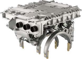
16 3 Air processing APU - Electronic Air Processing Unit 16
17 Air processing 3 17

18 3 Air processing In order to remove moisture and other hazardous materials such as oil from the compressed air, an air processing unit is integrated between the compressor and the air reservoir. APU - AIR PROCESSING UNIT Product benefits and characteristics Components The atmospheric air that the compressor sucks in contains a certain amount of moisture. That means that the compressor compresses a gas mixture of air and water vapour. The saturation limit of the moisture in the gas mixture, the so-called dew point, depends on the air temperature and the absolute humidity in this case. The heating of the supplied air during the compression phase of the compressor keeps the absolute humidity constant but the maximum possible moisture accumulation still increases. When the temperature falls, the portion of moisture condenses and is separated from the air as water. The Air-Processing Unit (APU) is a combination of various devices: This includes an air dryer with or without heating system, a safety valve and a tire valve. A multiple-circuit protection valve (also called: four-circuit protection valve) with one or two integrated pressure limit valves and two integrated check valves are flange-mounted on the air dryer. Some variations also have a double-pressure sensor, which is connected to the multiple circuit protection valve to measure the pressure in the brake circuits. The air dryer integrates the replaceable desiccant cartridge and the unloader valve. This independently regulates the operating pressure inside the compressed air braking system by interrupting the supply process of the compressor when achieving a defined shut-off pressure. APU components: Air dryer with regeneration function Desiccant cartridge Standard four-circuit protective valve with APU flange and bleed-back function (see section Several terms, described briefly ) or Four-circuit protective valve with APU flange and additional features such as pressure limiter or pressure sensor in some cases The modular construction of the unit enables simple installation of Air Processing Units. They combine excellent service properties with low space requirements. 18

19 Air processing 3 AIR DRYER Product benefits and characteristics Air dryers are responsible for reducing the portion of moisture in the compressed air. This is done by means of what is known as cold regeneration adsorption drying. The compressed air supplied by the compressor is routed over the granulate of the desiccant cartridge. This absorbs the moisture contained in the compressed air. The especially important regeneration of the granulate is done using a back-flushing process with air that has already been dried. The entire drying process is controlled by the air dryer. The air for regeneration is normally supplied from regeneration tanks, which usually have a volume of 5 litres. There are single- and dual-chamber air dryers. The basic variant, the single chamber air dryer can be used with flow rates of up to ~500 l/min. The regeneration of the desiccant is pressurecontrolled. The regeneration process is done using a single-chamber air dryer only during idle phase of the compressor, i.e. when the operating pressure has been achieved. Single-chamber air dryer Dual-chamber air dryers on the other hand cover a range starting at 500 l/min and compressor duty cycles exceeding 50%.. Here the regeneration is time-controlled. After 60 seconds cartridges are switched and the one not supplying air is then regenerated. The drying interval of 60 seconds is controlled by a solenoid valve with an integrated timer switch for dualchamber dryers. This ensures that good drying takes place even when duty cycles of the compressor are high. Dual-chamber air dryers are mainly used in vehicles with high air consumption. Air dryers are generally certified for a maximum operating pressure of 13.0 bar. Special variants (with a special cartridge) for up to 20 bar are available for special vehicles with high-pressure systems. Why is the correct drying of the air so important? Moisture penetrating into reservoirs and valves causes corrosion. This corrosion remains hidden to begin with but can then lead to the connected devices failing as surfaces rust. The moisture that remains in the tanks, decreases the storage volume and therefore the number of possible braking applications when the engine is stopped or can cause compressor failure. Experience shows that drivers trust the functionality of the air dryer and therefore seldom use the drain valve on the tanks. Engine oil lubrication for the compressor causes small quantities of oil to enter the compression chamber which then burn during the compression process because of heat generation. The cartridge of the air dryer filters the majority of these combustion products (such as oil particles for example) out of the compressed air. This prevents contamination and adhesion of the sealing surfaces of the brake valve over time. Highly developed engine oils extend the oil change intervals but are also associated with new hazards because of the chemical additives in the oils: These additives can convert into aerosols in the compressor and can get into the braking system. There they can attack the rubber parts of the valves. 19
20 3 Air processing The WABCO Air System Protector ( ), a Premium-Cartridge with coalescence filter, prevents the infiltration of these aerosols into the braking system and protects it from damage. To also ensure improved separation of oil residues and aerosols, WABCO has developed the Air System Protector PLUS cartridge ( ). Device overview Application Type Product number Various Omnibuses Single chamber MAN Single chamber Irisbus Dual chamber Setra, MAN, Napoleon Dual chamber Various Omnibuses Dual chamber Service and maintenance information Tips and other information for the workshop The air dryer function is tested by actuating the drain valves on the supply reservoirs. If water leaks out, this indicates a problem in the air dryer. In newer vehicles this is achieved by means of electronic sensors (condensation sensors). The air dryer must be checked for tightness and proper regenerating function. During this test, note any air outlet via port 3. Once the cut-off pressure is reached, the regeneration air will briefly continue to flow out of port 3 in the case of single-chamber dryers. In the case of dual-chamber dryers, there is a continuous flow of air during the supply phase. This outflow of air must not to be interpreted as a malfunction or even leak of the compressed air system. Oil leaking from the muffler of the air dryer can indicate that the compressor is pumping oil. In this case, the compressor should be checked following the specifications of the manufacturer. To gain the best efficiency, the inlet temperature of the compressed air should be around 28 C above the ambient temperature. The inlet temperature of the air in the air dryer should not be higher than 65 C. Too high an inlet temperature impairs the air dryer s function. If the compressed air system leaks, the regeneration cannot be initiated correctly. This can cause moisture to enter the system and result in failures of components or the compressed air system. No anti-freeze devices must be fitted upstream of the dryer. If the air dryer is equipped with a heating cartridge, this cartridge is switched on when the temperature drops below approx. 6 C and off again when it exceeds approx. 30 C. DESICCANT CARTRIDGE Product benefits and characteristics The quality of the air drying mainly depends on the desiccant used. In order to dry the air supplied by the compressor, specially designed desiccant beads with especially good drying properties and excellent mechanical resistance are used in WABCO cartridges. The latter ensures that the desiccant beads do not disintegrate into dust. Compared with the market standard granulate, the WABCO desiccant beads function more reliably and are easily recycled. 20


 has traces of oil, the Air System")
21 Air processing 3 As a premium solution, WABCO offers the Air System Protector PLUS Cartridge with integrated coalescence filter. This innovative product provides optimal protection against contamination and damage due to oil, moisture and aerosols. Greatest possible filter performance and a service life extended by around 50% make this an ideal cartridge for vehicles with an intensive air consumption even under toughest conditions. Operating principle of the Air System Protector PLUS cartridge Desiccant cartridge Air System Protector PLUS The following images clearly show the difference in using a standard cartridge and the Air System Protector PLUS (integrated coalescence filter). While the standard air dryer cartridge (Fig 1) has traces of oil, the Air System Protector PLUS (Fig. 2) shows no contamination. Figure 1: Desiccant cartridge without coalescence filter after 60,000 km Figure 2: Desiccant cartridge with coalescence filter after 60,000 km 21

22 3 Air processing Device overview Application Thread Product number Air System Protector PLUS cartridge M Air System Protector cartridge M Standard cartridge M Recycling cartridge M Service and maintenance information Tips and other information for the workshop On older devices, the safety screw must be loosened before replacement. The standard cartridge, as well as the WABCO Air System Protector should be replaced after two years under normal conditions. With the ASP Plus cartridge, WABCO recommends a replacement cycle of three years. Your WABCO partner guarantees that he will accept the return of the old cartridges. If any condensate is found, the regenerating function must be checked and the cartridge replaced as required. The air dryer must be depressurised for maintenance work. Before screwing in the new cartridge, the ring seal should be lightly greased. The tightening torque of the cartridge is 20 Nm (if present, tighten fastening screw). WABCO recommends: Regularly changing the cartridge(s) Frequent actuation of the drain valves on the reservoirs to check the air dryer function Taking problems with compressor or air dryer into account as possible causes when soiled or corroded components of the braking system are detected. FOUR-CIRCUIT PROTECTIVE VALVE Product benefits and characteristics Four-circuit protective valve Four-circuit protective valves, often referred to as multiple circuit protective valves, are used for controlling the supply of multiple, independent air pressure circuits on commercial vehicles for the service braking system and for the supply of secondary consumer devices. In the event of any circuit failing, that circuit is switched off automatically, the others continuing to be supplied with compressed air up to the opening pressure in the defective circuit. There are different types: Four-circuit protection valve with limited return flow in serial or parallel arrangement, with or without a bypass. Four-circuit protection valve in series connection with one or two integrated pressure limiting units and check valves for circuits (3) and (4), as well as electronic pressure sensors for circuits (1) and (2). To comply with directive 98/12/EC, the four-circuit protection valves are equipped with a bleed-back function (see: A few terms, briefly described ). 22
23 Air processing 3 Several terms, described briefly Device overview Opening pressure: Pressure that is required to open the circuit. Closing pressure (stabilisation pressure): Closing pressure is the pressure that triggers shutting down the failed circuit. A limited return flow enables, above closing pressure, a pressure equalisation between the respectively combined circuits. Series switching: This means that the ancillary consumers (circuits 3 and 4) follow the primary consumers (circuits 1 and 2). No return flow is possible from the ancillary consumers to the primary consumers. Parallel switching: In a parallel arrangement, all circuits are connected with one other. This means that a limited return flow from the ancillary consumers to the primary consumers is possible, and normal. Bypasses: These permit prioritised filling of systems equipped accordingly when the entire system is at zero pressure. They are often used in circuits 1 and 2. With valve variants in parallel arrangement, bypasses can also be used in circuits 3 and 4. Bleed-back function: The parking brake circuit 3 is connected to air circuit 1 via a throttled check valve. If the service braking system circuit 1 fails, circuit 3 is also vented to meet the requirements according to 98/12/EC (see below). Designation Product number Four-circuit protective valve Four-circuit protective valve Four-circuit protective valve Four-circuit protective valve Service and maintenance information Please note the requirements for periodic legal tests. Legal characteristics 6. Adaptation directive 91/422/EEC and directive 98/12/EC For vehicles with initial registration date after October 1994, the 6th Adaptation directive 91/422 EEC requires that, when the pressureless supply system is filled, the spring chamber brakes must only be released when the pressure in the service brake circuits is sufficiently high to effect actuation of the service braking system (BBA) to achieve the action required by the auxiliary brake. Directive 98/12/EC also requires that the actuated spring chamber brakes are only allowed to be released if the pressure in the service braking system circuits ensures at least the residual braking effect for loaded vehicles with the BBA for vehicles with the initial registration date after March Special maintenance that extends beyond the legally specified inspections is not required. What is tested is the closing pressure (or stabilising pressure) with the engine stopped. Pressure in the circuit that has not failed must not drop to the respective closing pressure. This test must be repeated with a simulated defect in the other circuits respectively after the system has been refilled. 23


24 4 Driveline Control Driveline Control 24
25 Driveline Control 4 25


. This causes a cartridge to open and air pressure from the engine s compressor to enter a pneumatic chamber.")
26 4 Driveline Control CLUTCH CONTROL WABCO has more than 40 years experience in Clutch Servos Clutch Servos have been used in buses for over 40 years. When buses started growing in capacity, the engine and drive train had to grow with it. Clutches had to cope with higher torque and power loads, therefore they became heavier and more robust in design. The problem arose that drivers were no longer able to engage the clutch without hydropneumatic assistance. Clutch Servos are based on the principle of air-hydraulic assistance. When the driver activates the clutch pedal, hydraulic pressure from the clutch pedal s master cylinder (mounted under the cabin) is built up in the clutch servo (mounted against the clutch bell housing). This causes a cartridge to open and air pressure from the engine s compressor to enter a pneumatic chamber. A pneumatic piston is forced forward by air pressure and distributes its power towards the clutch lever via a steel pushrod. The clutch group is activated and the clutch disengaged. The driver can now shift the desired gear without damaging the gearbox. When the driver releases the clutch pedal, hydraulic pressure goes back to the master cylinder and forces the cartridge in the clutch servo to close again. The air pressure in the pneumatic chamber can now escape to the exhaust and the steel pushrod moves back inwards. The clutch group is released and the clutch engaged. 26
. The IPU consists of the clutch pedal as well as integrated throttle and brake actuators.")

27 Driveline Control 4 Master cylinder The master cylinder is mechanically connected to the clutch pedal and translates the drivers foot force into hydraulic pressure. The master cylinder can also be integrated in the IPU (Integrated Pedal Unit). The IPU consists of the clutch pedal as well as integrated throttle and brake actuators. Specifications: Clutch servos in buses can be found in different pneumatic cylinder diameters, mostly 3" or 4", depending on the clutch and gearbox. With stroke sensor, mechanical wear indicator or 3/2 way valve Mineral oil or brake fluid Service and maintenance information Important! Never activate the clutch servo or the clutch pedal if the clutch servo is not installed in the vehicle. Otherwise the clutch servo will be damaged. Repair: It is imperative that the vehicle manufacturer s specifications and instructions are complied with. Clean the cables and connections on the vehicle before filling. Only use new hydraulic fluid that has been authorised for the clutch servo (mineral oil or brake fluid). Reuse of hydraulic fluid is not permitted. First, fit the linkage. Screw the clutch servo to its bracket. Ensure a correct seat on the clutch housing. Connect the pneumatic lines. Connect the hydraulic lines. Bleed the hydraulic system. 27

28 4 Driveline Control RETARDER CONTROL Segment description Retarders or wearless brakes (permanent brakes) have been popular devices on buses for a long time. Retarders were introduced to ensure safe, efficient and secure road grip when driving down long slopes. In some regions they were needed to fulfil legal requirements - StVZO 41 (15) in Germany for example. Retarders or wearless brakes (permanent brakes) can function on the basis of different principles, such as hydrodynamic, electromagnetic or pressure build-up concepts. They all have one thing in common: a friction-free means of braking the vehicle. The vehicle s dynamic force is converted into heat or pressure so that the mechanical drum or disc brakes can be partly or fully relieved when the vehicle is braked over long periods of downhill driving. Hydrodynamic retarder Product advantages and features The hydrodynamic retarder is controlled by an ECU and a proportional valve. The ECU collects vehicle parameters and commands the proportional valve accordingly. Some hydrodynamic retarder variants use WABCO devices for the proportional valve, for example, which is mounted directly to the retarder. The variant depends on the retarder solution/application. Device overview Application Type Product number VOITH Retarder Proportional valve Retarder ECUs are available only from manufacturers/suppliers of retarders or vehicle manufacturers. 28


29 Driveline Control 4 Service and maintenance information Devices are maintenance-free. Repair kits are not available. If necessary, the device needs to be replaced. Engine brake Product advantages and features Engine brakes are mounted directly on the cylinder head, but the precise variant depends on the engine type. The engine brake can effect the vehicle s retardation quickly and with precision by means of the engine. Here the exhaust valve is opened by the engine brake just as the power stroke begins, thereby preventing the compressed air from supporting the downward motion of the piston. Device overview Application Type Product number IVECO Cursor engines Cylinder Control unit Service and maintenance information Devices are maintenance-free. Repair kits are not available. If necessary, the device needs to be replaced. Exhaust brake Product advantages and features The engine retarder controls the engine s exhaust back-pressure to improve the engine brake efficiency over the complete range of speeds. It contains a pneumatic or vacuum actuator controlling a throttle valve that is mounted directly to the exhaust manifold. Device overview Several applications in South America and India. Service and maintenance information Devices are maintenance-free. It is permissible to clean and lubricate it using a suitable grade of WABCO approved lubricant. 29


 are part of a single unit.")
30 4 Driveline Control TRANSMISSION AUTOMATION Segment description Product advantages and features OptiDrive components: Gear actuator, clutch actuator, shift lever unit, range cylinder AMT Automated Manual Transmission is a system that converts a manual into an automated transmission. The bus does not have a clutch pedal. The driver may choose between manual and automatic mode. In manual mode the driver initiates gear changes via a gear control unit but the AMT executes the gear shift automatically. In automated mode, gear changes are initiated and executed automatically by the AMT system, depending on the requested speed and driving conditions. AMT systems may have different configurations: European modular system, comprising shift cylinders with integrated ECU, range cylinder, split cylinder and sensors. Here the components are mounted to the transmission according to their function and replace manual actuators on standard transmission. This configuration enables a flexible solution for automation in existing transmissions. An integrated transmission control unit where all AMT components (ECU, shift actuators, solenoid valves and sensors) are part of a single unit. This unit is directly mounted to the transmission or even partially integrated in the gearbox. This customised solution is advantageous for high performance transmissions which are specially designed for automation. OptiDrive is a modular AMT system that includes gear actuator, clutch actuator, range cylinder, split cylinder, gear lever unit with integrated ECU or cabin-mounted standalone ECU and speed sensors. Its components can be adapted to existing manual transmissions and are mounted accordingly. OptiDrive s state-of-the-art system functionality offers an efficient and effective solution for gearbox automation of 5-16 speed transmissions. Gear actuation is realised with pneumatic or hydraulic mechatronics. Different sensors provide the system with information on transmission speed, pressure and shifting distances. 30

 Product number 421 350 085 0 421 350 086 0 Based on this modular system, WABCO s AMTs provide enhanced system integration into existing or new")
31 Driveline Control 4 The AMT system is equipped with an ECU Electronic Control Unit receiving relevant information from other vehicle components, e.g. engine ECU, via CAN SAE J WABCO offers software development for several transmission control applications, such as transmission shift procedures, clutch control, system diagnostic, etc. Currently, KWP2000 is used as the diagnostic interface. Additional device Type EPS 3 (Gear cylinder) Product number Based on this modular system, WABCO s AMTs provide enhanced system integration into existing or new transmissions. Furthermore WABCO offers high performance software models for various applications. Automated Manual Transmission For vehicle manufacturers, the benefits of AMT systems are: Improved efficiency: Reduced vehicle weight No clutch pedal No synchronized transmission necessary No linkage between cab and chassis Simplified assembly Operational reliability Decreased shift errors and overspeed situations Increased protection against external influences Easy access Simple and robust design of transmission and all components For drivers, the benefits of AMT systems are: Improved efficiency: Increased fuel economy Extended clutch and transmission life Increased payload Improves performance of inexperienced drivers Operational reliability Less gear change and clutch errors Gear shifting within optimum speed range Safety Fast selection of gears, particularly in challenging situations Comfort Easy handling: effort for shifting is reduced Less stress for the driver, especially when moving in metropolitan areas Service and maintenance information Service and maintenance is fully provided by vehicle manufacturers. 31


32 5 EBS - Electronic Braking System EBS - Electronic Braking System 32


33 EBS - Electronic Braking System 5 33
 make sure that the vehicle is securely decelerated. EBS BASIC FUNCTION WABCO EBS operates with electronic signals.")
34 5 EBS - Electronic Braking System A sophisticated concept makes EBS one of the safest braking systems in utility vehicles. In this case, several brake circuits (redundancy) make sure that the vehicle is securely decelerated. EBS BASIC FUNCTION WABCO EBS operates with electronic signals. The EBS electronic control unit controls the system through these signals and can communicate with the individual components at any time. The valves on the brake cylinders generate the required braking pressure according to the control signals. Speed sensors, installed on the wheels of the vehicle for the integrated ABS function, constantly provide the EBS with up-to-date wheel speed information. Different integrated brake management functions detect any deviations from normal driving conditions and intervene in the driving process in the event of hazards. Apart from improving safety, specific functions also optimise driving comfort and lining wear. If the electronic control system malfunctions, all valves simultaneously coordinate operation as in a conventional pneumatic system. In this case, backup pressures are conducted to the brake cylinders where the pneumatic system is effectively applied. What is known as a backup valve blocks the effect of the pneumatic circuit on the rear axle brake cylinders while EBS functions normally. 34
35 EBS - Electronic Braking System 5 Product advantages and features Braking comfort and improved safety through EBS The driver enters his deceleration command by operating the brake. EBS then electronically transmits this command to all braking system components. Response and build-up times at the brake cylinders are reduced significantly due to electronic actuation. The ECU also facilitates a sensitive application of the braking system during this process. The result: a comfortable braking feeling, independent of the load status, and a much shorter braking distance. The functions integrated in EBS ensure that both the vehicle s driving stability and steerability are maintained during the braking process. The Differential Slip Control (DSC) system automatically distributes the braking forces between the front and rear axle according to the respective load status. The integrated anti slip regulation applies traction control. Lining wear optimisation and ease of maintenance through EBS EBS from WABCO provides the option to continuously monitor and balance lining wear. The Brake Lining Wear Control intervenes in the distribution of braking forces during uncritical braking events if a difference in the linings of the different axles is detected. This means that service and lining replacement times can be coordinated. All linings on the vehicle are then replaced simultaneously. The integration of endurance brakes, such as retarder and engine brake, also help to protect brake linings for longer operating times. Extensive integrated diagnostic and monitoring functions constantly carry out self-inspections of EBS. Corresponding warnings will alert the driver immediately if operational readiness is impaired. A diagnostic device or the on-board diagnostic display in the vehicle can be used to determine the causes quickly and easily. Maintenance and workshop periods can also be significantly reduced by means of the extensive test functions of the diagnostic system. Integrated brake management functions of a modern EBS Stability control Feature Anti-Lock Braking Function (ABS) Integrated Automatic Traction Control (ATC) Electronic Stability Control (incl. RSC) Engine / Drag Torque Control Benefit Prevents locking of wheels and maintains steerability for more safety Maintains control of the vehicle even on slippery surfaces Increases protection against tipping over, skidding, spinning and jackknifing Improved stability on slippery surfaces 35
36 5 EBS - Electronic Braking System Brake control Feature Deceleration Control Brake Force Distribution Endurance Brake Integration (Brake Blending) Hill Start Aid / Hill Holder Halt Brake Benefit Same brake performance regardless of the load Optimal distribution of braking pressure leads to shorter braking distances and more safety Less brake lining wear Increased road safety by preventing rolling back / Driver assist and safety functionality during daily operation Driver assist and safety functionality during daily operation Performance monitoring Feature Tire Pressure Indicator Lining Wear Control Brake Temperature Monitoring Brake Performance Monitoring Hybrid support Benefit Reduced wear and maintenance costs Reduced maintenance costs Reduced maintenance costs Increased road safety Regenerating braking, fuel savings 36
37 EBS - Electronic Braking System 5 FUNCTIONS AND FEATURES Anti-Lock Braking Function Inductive sensors measure the rotational speed of individual wheels so that any tendency to lock is detected early. The EBS ECU can reduce, stop or increase the braking pressure for the brake cylinders on the front axle accordingly via the ABS solenoid valves. The axle modulator at the rear axle (optional at the additional axle), whose electronic control unit includes the relevant control algorithms, performs the same task. Integrated Automatic Traction Control (ATC) The ATC function detects the tendency to spin and reduces the driving torque via the engine control electronics. If only one wheel tends to spin, ATC differential braking will be applied to it. Engine control interventions as well as differential brake control interventions may act in parallel. Electronic Stability Control (ESC) ESC is an extension to the EBS system. While EBS is responsible for stability during driving and braking in longitudinal direction, ESC aims to increase vehicle stability during manoeuvres like cornering and lane change. Using the information from various sensors, the ESC system detects such critical situations and adjusts engine and braking power accordingly as required. This assists the driver and improves road safety. Engine / Drag Torque Control Drag torque occurs in the driveline due to gear shifting or gas exchange. The resulting braking torques can cause the driving wheels to lock, making the vehicle unstable. The Drag Torque Control function prevents this situation. When a defined slip state is exceeded, the engine torque is increased relative to the speeds of the driving wheels, reducing the drag torque that occurs. The Drag Torque Control terminates as soon as the driving wheel values are stable again. Deceleration Control / Braking Force Control The Deceleration Control function is used to adjust the braking pressure level to the braking command from the driver. EBS ensures that with identical pedal operations the vehicle is always braked with the same effect, regardless of the load status. If the brake linings are wet for example, EBS will increase the braking pressure until the desired deceleration is achieved. For this reason there is no need for a separate axle load sensing system for braking force control. 37
38 5 EBS - Electronic Braking System Brake Force Distribution The distribution of braking forces depends on different vehicle measurements and data. An evaluation of the sensor signals provides exact information on the slip on each axle and thus their braking performance. If the slip differs, one axle contributes more towards deceleration than the other. Consequently, this axle is also subject to greater wear. EBS applies differential slip control to regulate the pressures on each axle for optimum distribution of braking forces. Endurance Brake Integration (Brake Blending) The Endurance Brake Integration function ensures the full integration of available endurance brakes to all brake applications automatically only by normal brake pedal actuation. It ensures that the endurance brakes, such as retarder and engine brake, contribute the maximum possible portion of braking torque for the vehicle as a whole. The wheel brakes thus stay cool, reducing wear of brake linings and drums or brake discs. Different control strategies for the Endurance Brake Integration function are available for city busses as well as for coaches and for different drivelines (e.g. hybrid). Hill Start Aid / Hill Holder EBS offers automatic roll brake functions to allow the driver to comfortably start uphill by preventing the vehicle from rolling backwards. Variants differ according to activation conditions. The function may be selected by a switch signal. The driver has to activate the function by briefly tapping the brake pedal. The system will hold the brakes as long as the activation conditions are fulfilled. If the incline is too steep for the preselected brake pressure the driver may increase the holding pressure by actuating the brake pedal with increased force. After the driver stepped off the brake pedal, the pressure will not be released before the transmission reports ready for brake release or after a predefined period of time has elapsed. For safety reasons the EBS monitors the required operation of at least one pedal by the driver (clutch, brake or accelerator). This is designed to avoid misuse of hill holder as a parking brake. 38
39 EBS - Electronic Braking System 5 Halt Brake The driver activates the Halt Brake via switch. The request actuate the halt brake is sent to the EBS ECU via the CAN Bus or a hardwired switch signal. This signal can also be combined with appropriate external functions like a door control or other devices which indicate a short stop. Using the EBS modulator(s), the brake cylinders are supplied with the respective braking pressure on the front and rear axle(s).the pressure levels of the individual axles are adjustable by parameter as well as application and release gradients. The Halt Brake is deactivated via the hardwired switch or via a CAN signal sent by an external device. Deactivation may also be triggered by actuation of the accelerator pedal. The braking pressure will be released by a predefined gradient to permit driving off. A combination of the Halt Brake function and engine control may be selected to limit the engine torque during a stopping interval. Special features with WABCO EBS in buses: Besides conventional drivetrains, EBS supports a variety of hybrid and purely electric drivetrains (e. g. series hybrid, fully electric and trolley buses). The EBS system is optimised for maximum energy recuperation during braking processes without additional driver intervention, apart from pressing the brake pedal. The comfort stop function ensures a smooth braking action without harsh jerks by slightly decreasing braking pressure just before standstill. Additionally, the braking pressure can be distributed to the rear axle shortly before standstill to increase braking comfort, especially in city buses. In buses, EBS works with two or three axle modulators, depending on vehicle type (three axle or articulated bus) and drivetrain layout. 39
 2 10 1 Power Supply Switches / Lamps Trailer CAN ISO 11992 1 EBS central module 2 Brake signal transmitter 3 1-channel axle modulator 8 ω 9 L V2")

40 5 EBS - Electronic Braking System EBS COMPONENTS IN BUSES System Layout EBS3 / System Configuration 4S / 4M with LWS SAE J1939 vehicle data bus pneumatic line pneumatic control line electrical connection CAN connection (may include power supply) Power Supply Switches / Lamps Trailer CAN ISO EBS central module 2 Brake signal transmitter 3 1-channel axle modulator 8 ω 9 L V2 V L ω 4 2-channel axle modulator 5 Trailer control valve 6 ESC control module 7 ABS solenoid valve 8 ABS sensors 7 3 V2 V1 4 9 Wear sensors 10 Steering angle sensor ω L 7 V3 Parking Brake Control L ω Central module Brake signal transmitter The central module controls and monitors the electronically controlled braking system. It determines the vehicle s nominal deceleration from the signals received by the brake signal transmitter and external deceleration demands (e.g. ACC, AEBS). The set deceleration and wheel speed measured through the speed sensors create a collective input signal for the electro-pneumatic control system. The central module calculates the pressure values for the front axle, the rear axle, the additional axle in a 6S6M system and the trailer from the input signals. The brake signal transmitter receives the deceleration request from the driver via the brake pedal and generates the electrical signals and pneumatic pressures for charging and venting the actuators. The device has a dual-circuit electronic and a dual-circuit pneumatic structure. When actuating the brake pedal, two mechanical switches are initially actuated. These are connected to the electronic control unit and are used for the operational execution and monitoring of the braking procedure. The pedal stroke is recorded by two sensors and transmitted from the Brake Signal Transmitter as a Pulse Width Modulated signal (PWM). 40


 controls the pressure at the coupling heads.")

41 EBS - Electronic Braking System 5 Since the introduction of EBS into serial production in 1996, WABCO has developed four axle modulator generations. The new design of a 1-channel version is intended for front and rear axles. In a 2-channel version, the axle modulator is used on rear axles only. The axle modulator in different variants controls the brake actuator pressure on both sides of a single or dual axle; on the front axle as a 1-channel modulator version, on the rear axles as 1- or 2- channel modulator version. 1-channel axle modulator 2-channel axle modulator The axle modulator records the wheel speeds, using speed sensors, evaluates and sends them via the CAN bus to the central module, which subsequently calculates the nominal pressure. ABS control is applied directly by the rear axle modulators. If a wheel locks or spins, the rear axle modulator modifies the nominal pressure. The front axle modulator supports the ABS function on the front actuated by the ABS solenoid valves, which are fitted to control the pressure on the front axle brake actuators. Provision is made on specific device variants for connecting two sensors to detect brake lining wear. All axle modulators are equipped with an additional connection for the backup pressure control circuit of the brake signal transmitter. 6S/5M or 6S/6M systems can be designed with three axle modulators for controlling the individual wheels. The Trailer Control Valve (TCV) controls the pressure at the coupling heads. In this way it controls the braking behaviour of the trailer using an electro-pneumatic circuit and a pneumatic circuit. It receives the nominal pressure values from the Electronic Control Unit. Trailer control calve For the ESC functionality, an ESC (Electronic Stability Control) module and a steering wheel angle sensor (SAS) have to be attached to the system CAN bus. The ESC module contains a yaw rate sensor to measure the vehicle s rotary motion around its vertical axis as well as an acceleration sensor to measure the lateral acceleration and both provide this information on the CAN data bus. ESC control module The Steering wheel angle sensor is installed at the steering column of the vehicle and provides a measured value of the absolute angle (position) of the steering wheel. This includes the capability of identifying the steering wheel zero position (centre position) by means of sensor calibration. Steering wheel angle sensor 41


42 5 EBS - Electronic Braking System Hand-brake valves are used for actuating the secondary and the parking brake system. In this case a sensitively stepped actuation of the handlever pressurises or depressurises the Spring Brake Actuators. Hand-brake valve Device overview Application Name Product number Evobus / Daimler Electronic Control Unit Evobus / Daimler Brake Signal Transmitter Evobus / Daimler Hand Brake Valve Evobus / Daimler Axle Modulator 2 Channel Evobus / Daimler Axle Modulator 1 Channel Evobus / Daimler Electronic Stability Control (ESC) MAN Hand Brake Valve Standard Bus Electronic Control Unit x 0 Standard Bus Brake Signal Transmitter without pedal Standard Bus Brake Signal Transmitter with pedal 25 C Standard Bus Brake Signal Transmitter with pedal 46 C Standard Bus Axle Modulator 2 Channel Standard Bus Axle Modulator 1 Channel Standard Bus Axle Modulator 2 Channel with bridge option Standard Bus Trailer Control Valve Standard Bus Electronic Stability Control (ESC)

43 EBS - Electronic Braking System 5 Service and maintenance information Monitoring functions An EBS system is basically maintenance-free. It monitors itself and its components independently. If a fault occurs, a message is sent to the driver indicating that the vehicle should be taken to a workshop or that it should no longer be operated. Various fault recognition functions are integrated in EBS Warning notice: To ensure safe function of the overall EBS system, a defective component must be replaced as a unit. In these cases it may become necessary to transfer the parameter sets from the ECU to the new component. Checking the braking action Whether the braking action of a vehicle satisfies legal requirements is generally tested on a roller test stand in the workshop. For this purpose, it is necessary to brake each axle with the maximum possible force. At the same time the EBS brake management functions, such as load-dependent braking force control, must remain unimpaired. Legal requirements Visual and function test during safety testing Note: A safety and functionality test (SP) of commercial vehicles may only be performed by correspondingly trained personnel on the basis of legal requirements. Please observe the information provided by the vehicle manufacturer. Inspecting the warning equipment The EBS has a much more advanced self-monitoring system than the previous ABS system. Faults detected in the vehicle are saved and indicated to the drive via warning lamps or the display. This warning equipment must be checked for proper function during the safety check. Checking the air supply system Checking the air supply system is identical to the procedure for conventional braking systems. Checking the wheel brake Wheel brake effectiveness can be checked on a roller test stand, analogous to any other compressed air braking system. Projection Projection is subject to the same process as conventional braking systems in vehicles. Note the vehicle manufacturer s specifications for calculating pressure values. 43


44 6 Wheel brakes Wheel brakes 44
45 Wheel brakes 6 45


 calculations and the unique single-piston The PAN")

46 6 Wheel brakes This chapter introduces the compressed-air disc brakes of the PAN and MAXX series that have enjoyed great market success - in particular with regard to application in buses. While previously wheel brakes were simply required to provide safety, decrease speed and stop the vehicle, the focus for product innovation today also concerns installation space, weight, comfort, maintenance times and costs. PAN COMPRESSED-AIR DISC BRAKES Compressed-air disc brake PAN 19 Outstanding reliability of WABCO s compressed-air disc brakes with single-piston technology The WABCO PAN series has become one of the most successful compressed-air disc brake concepts for commercial vehicles due its reliable and proven technology. The compact design with low weight is based on the elaborate combination of FEM (Finite Element Method) calculations and the unique single-piston technology. The PAN brake s reliability is enhanced by an encapsulated guidance system with robust metal fasteners as well as redundant seal systems for the guidance system and the adjuster unit. The result is a significant reduction in vehicle weight for all vehicle classes as well as outstanding reliability, which is reflected in high customer satisfaction. Benefits Compact design enables easy axle adjustment Excellent braking performance even in difficult road conditions CDP coating as standard corrosion protection for longer service life High quality standard reduces maintenance and warranty costs Significant reduction of the braking distance as compared to drum brakes. 46


47 Wheel brakes 6 Selective product overview PAN 17 Vehicle application Anadolou Isuzu Otokar Otomotiv OE reference WABCO brake PAN 17 Replacement brake PAN 17 Brake pad repair kit VT VT 13C C MAXX COMPRESSED-AIR DISC BRAKES New single-piston compressed-air disc brakes with optimum weight to performance ratio MAXX the new complete WABCO range of compressed-air disc brakes for the extreme demands in trucks, buses and trailers around the world. The MAXX disc brake range will represent the lightest and most powerful compressed-air disc brakes with singe-piston technology for the commercial vehicle sector on the market. The outstanding, compact design of MAXX compressed-air disc brakes from WABCO reduces the overall weight of the vehicle, increasing the fuel efficiency or the payload. Compressed-air disc brake MAXX 22 Product properties New generation of compressed-air disc brakes for all common wheel sizes Reinforced actuating unit in a monoblock brake calliper Redundant seals combined with robust metal fasteners Replaceable brake pad wear sensor (analogue or wear indicator) Benefits Light-weight construction in combination with a high braking torque provides an outstanding weight-performance ratio Bidirectional reset unit ensures optimum clearance and helps to avoid running hot Replaceable plug-and-play sensor reduces maintenance costs High reliability thanks to tried and tested single-piston technology Significant reduction of the braking distance as compared to drum brakes Pad wear indicators (BVA) Wear indicators Depending on the vehicle, wheel brakes are delivered with pad wear indicators (BVA). This makes the vehicle safer and downtimes for maintenance more predictable. The thickness of the pad is monitored permanently with these wear indicators. If the pad reaches its critical wear limit, warning lamps indicate that the brakes require maintenance. 47


48 6 Wheel brakes Continuous wear sensor (CWS) As an alternative, a continuous wear sensor (CWS) provides information on the current pad wear status. In combination with an EBS, the braking system uses sensor signals to compare the wear of the pads on all axles and wheels by controlling the pressure of the different axles and monitoring the thickness of the brake pads on all wheels. In this way, all brake pads are worn evenly. If the critical pad thickness of the brake pad is reached, it is indicated via the ABS-/ EBS-warning lamps on the instrument board so that the driver is informed of a required brake service. Another benefit: The continuous wear sensor (CWS) can be easily replaced - plug-and-play - without the need for further settings, as was the case with the BVA. You will find information about the replacement parts on the Internet in our product database INFORM. BRAKE SOLUTIONS FOR PORTAL AXLES Radial brake + Standard TRISTOP WABCO brake cylinders are used by many major commercial vehicle manufacturers and have proven their reliability in millions of applications. In many buses the axial compressed-air disc brake MAXX with the Compact TRISTOP can be used instead of a heavy radial brake - taking into account the special installation situation in this vehicle segment. Benefits Enables the installation of lighter axial brakes Identical brake design on front and rear axle Weight reduction due to lack of unwieldy, heavy radial brake Axial brake + Compact TRISTOP Technical data Standard TRISTOP Type 20/24 Length 259 mm 202 mm Diameter 191 mm 246 mm Weight (4 brakes, 4 brake cylinders) 207 kg 186 kg Braking force kn* kn* Release pressure 6 bar 6 bar * complies with the legal requirement of 5.3 kn Compact TRISTOP Type (30)/14 48

49 Wheel brakes Compressed air disc brake cross section 1 Screw 2 Brake pad 3 Retainer clip 4 Wear indicator 5 Retainer spring 6 Piston protection cap 7 Redundant seal 8 Sealing plug Service and maintenance information Before carrying out work on brakes, it is essential that you refer to the respective service instructions. Only start repair work if you have read and understood all (safety) information that is required for the repair. Tips and other information for the workshop Legal characteristics Brake pads must always be replaced per axle. With glued or riveted pads, the special adhesive regulations and drawings must be observed. With each brake pad replacement on disc brakes, the retainer springs and pad retainer clips must also be replaced. Use only the pads that are approved by the vehicle manufacturer. When fitting spare parts, please bear in mind that these have to be fitted without using force. When carrying out maintenance work, check all seals for damage and replace as necessary. On vehicles that are allowed to be driven on public roads, the regulations according to 29 StVZO apply. The safety test is also required.

50 7 Brake cylinder Brake cylinder 50


51 Brake cylinder 7 51


52 7 Brake cylinder Brake cylinders provide the required force to execute the braking procedures for the wheels in combination with the wheel brakes. This converts the pneumatic energy into mechanical motion energy. Brake cylinders are designed to perform reliably and safely for many years. The highest quality standards ensure a noticeable reduction in operating costs and greatest possible safety. Major features that distinguish cylinders are size, stroke, piston length, spring chamber strength and overall length. The following product types of brake cylinders are installed in buses: UNISTOP Diaphragm brake cylinder TRISTOP Spring chamber brake cylinder Both types exist in diverse variants for disc brakes, S-cam brakes and expansion wedge brakes. UNISTOP DIAPHRAGM BRAKE CYLINDER WABCO diaphragm brake cylinders are used by many major commercial vehicle manufacturers and have proven their reliability in millions of applications. With more than 500 variants, diaphragm brake cylinders offer many different options for compressed-air disc, S-cam and expansion wedge brakes. UNISTOP Diaphragm brake cylinder for disc brakes Product properties: Operating pressure up to 13 bar Stroke length up to 75 mm Piston rod can be supplied in different lengths Various connection positions and thread types Diaphragm brake cylinders are a component of the service braking system and are normally installed on the front axles. 52


53 Brake cylinder 7 Device overview UNISTOP Diaphragm brake cylinder for disc brakes Application OE reference Type Product number MAN, Neoplan MAN, Neoplan UNISTOP Diaphragm brake cylinder for cam brakes Application OE reference Type Product number Mercedes-Benz A Mercedes-Benz A TRISTOP SPRING CHAMBER BRAKE CYLINDER TRISTOP spring chamber brake cylinder for disc brakes Brake cylinder with service, parking and emergency brake function The WABCO TRISTOP - a technology that is one of the market leaders in Europe - has been tried and proven in millions of applications. It is one of the most mature products on the market. With more than 1,500 variants for compressed-air disc, S-cam or expansion wedge brakes, TRISTOP is easily adapted to customer requirements. The integrated breather valve (IBV), the powerful parking brake spring as well as different release systems (standard, half release screw, integrated release screw with indication) have contributed substantially to the technological standards of today. Product properties: Operating pressure up to 13 bar Stroke length up to 75 mm Piston rod can be supplied in different lengths Various connection positions and thread types Normally used on the drive axle Device overview TRISTOP cylinder for disc brakes Application OE reference Type Product number MAN / MAN / TRISTOP cylinder for S-cam brakes Application OE reference Type Product number Bova Setra Bova Setra Q Q / / Setra Q / Setra Q / For the TRISTOP cylinders listed above for cam brakes, the Universal TRISTOP cylinder / can also be used. 53
54 7 Brake cylinder Service and maintenance information Special maintenance that extends beyond the legally specified inspections is not required. The cylinders must be tested for tightness, correct fastening and actuator stroke during full braking. With a correctly adjusted wheel brake, the diaphragm stroke should be one third to max. half of the possible total stroke. The diaphragm brake cylinder is set up for a response pressure of 0.2 to 0.3 bar. If the response pressure exceeds 0.5 bar, an internal inspection is required. When replacing the cylinder, the console must be checked for damage and replaced according to the recommendations of the axle manufacturer or the vehicle manufacturer as required. The opened drain/breather hole must point downward. Additional drain holes must be closed and the fastening nuts tightened to 180 to 210 Nm. The piston rod of Universal TRISTOP cylinders with bellow seals must only be shortened to the extent that the bellows will not be damaged during operation. To achieve the braking force determined by the brake calculation, a replacement requires that the same size of WABCO TRISTOP is used as the original installation by the vehicle manufacturer. Tips and other information for the workshop What is IBV? A breather valve integrated in the cylinder makes the small external connecting tube between the parking brake component and the service brake component redundant. This technology provides a multitude of advantages: Long service life of the brake cylinder Only dry and clean air in the spring chamber for the parking brake Reduced expenditure for adaptation the position of the breather tube does not need to be considered Greater variability more variants can be used as a replacement due to the greater adjustment range Lower logistic requirements because there are fewer variants Original cylinder with external tube can easily be replaced with an IBV type. What does 24/24 mean, for example? The type information (e.g. type 24/24) indicates the effective piston surface (in square inches) in the diaphragm and spring chamber part. With TRISTOP cylinders, a simultaneous actuation of the service and parking brake system can lead to an addition of braking force in the wheel brake. If this is to be prevented, an overload protection valve or a two-way valve should be installed upstream. 54


55 Brake cylinder 7 These are some of the points that must be observed when switching to a Universal TRISTOP cylinder: Position of the clamp band Position of the threaded connections Position of the breather tube Position of the drainage hole, closed at top, open at bottom Length of the piston rod The piston of the TRISTOP cylinder must be retracted completely while the brake is not actuated and must not be pre-tensioned. A test of the effectiveness is to be performed on the brake test stand. TRISTOP cylinders must be replaced per axle! For older cylinders, the spring force of the spring chamber can be weakened, which will cause uneven braking. When replacing cylinders, make sure they are installed correctly and that the seal to the disc brake is not damaged. Note: Never open the housing to the spring chamber! Risk of fatal injuries due to parts coming explosively apart. The spring chamber part is only to be replaced as a complete unit. TRISTOP cylinder with IBV and IMA, schematic diagram Spring no "coil-clash no abrasion, reduced corrosion long-lasting spring force Inside release screw with indication (IMA) high flexibility with small installation spaces Cylinder completely powder-coated bayonet lock Integrated breather valve (IBV) no external line longer service life fewer variants more installation options Diaphragm long service life Seal plastic centring ring 55


56 8 Chassis and Suspension Systems ECAS Electronically Controlled Air Suspension 56


57 Chassis and Suspension Systems 8 57

58 8 Chassis and Suspension Systems ECAS is an electronically controlled air suspension system for buses, trucks and other commercial vehicles that includes a variety of functions within an all-in-one system. Air suspension in buses has almost completely replaced the standard mechanical suspension systems. Product advantages and features ECAS ELECTRONICALLY CONTROLLED AIR SUSPENSION The advantages of electronic air suspension are primarily seen in the combination of many different functions. Advantages of ECAS: Constant vehicle height regardless of total weight Decreased air consumption: It was found that ECAS can save around 25% of air in low-floor buses during normal operation as compared to conventional air suspension systems Extensive safety concept, diagnostics memory and diagnostic capabilities High speed for all control processes with large valve cross-section (nominal diameter up to 8 mm per bellow) Fewer components: From the solenoid block, only one line runs to each bellow and one line to the supply reservoir High system flexibility for different kneeling types Protects road surfaces System functions The ECAS electronic controls are based on the measurement values from the sensors of the air suspension system. Besides controlling the normal level, the electronics cover in combination with operational switches and sensors for tire impression compensation control of the remaining functions as well. Latest ECAS generations are purely CAN bus systems. ECAS includes the following functions among others: Nominal level control Normal level I and II Height limitation 58

59 Chassis and Suspension Systems 8 Kneeling Supply pressure monitoring Raising and lowering the front and rear axles Not all of the capabilities are necessarily integrated into every system. Note: The system configuration and parameter settings are the vehicle manufacturer s responsibility and must not be changed without the vehicle manufacturer s consent. The safety concept For monitoring the proper functionality of the system, the ECU checks the majority of the electrical connections in rotation and compares the voltage and resistance values with specified values. The signals of the sensors are also checked for plausibility. An unchanged level despite a support bellow being pressurised, for example, is implausible and is therefore classified as a fault. Recognised information is indicated to the driver via a display in the instrument panel. Nominal level control If there are deviations from the specified level above a tolerance range, solenoid valves are actuated and the actual level is adjusted to the specified level by pressurising/depressurising the air suspension bellow. Driving levels that have been defined previously are also maintained, independent ly of the number of passengers that get in or out for example. Normal level I / II Normal level I is defined by the vehicle manufacturer for normal driving operation. This level determines suspension comfort, driving safety and the installation height. Normal level II deviates from normal level I. This is defined by a parameter in the electronics. A switch is used to select between normal level I and normal level II. For reasons of safety, the normal level can be adjusted automatically if the vehicle exceeds a predefined speed limit; after dropping below a lower speed limit, the level is adjusted to the previous level again. Height limitation A height adjustment is ended automatically if value parameters for the upper and lower end position are reached. Kneeling Kneeling is a special function for buses (see Legal characteristics at the end of the chapter as well). Kneeling is tilting the bus to ease the entry and exit for passengers. This can be done on the entire side, on a single wheel or on an axle by means of a distance sensor. ECAS can also ensure a proper lowering procedure using a contact strip. Supply pressure monitoring ECAS does not allow kneeling if the existing supply pressure is insufficient to raise a lowered, fully loaded vehicle to its normal level again. 59


.")
.")

60 8 Chassis and Suspension Systems ECAS components Electronic Control Unit (ECU) The electronic control unit is the core of the system to which the individual components are connected by means of plug-in connections. ECAS-CAN electronic control unit bus Solenoid valves By combining specially developed solenoid valves into compact block valves, the required installation space and effort is greatly reduced. The solenoid valves, controlled as actuators by the electronics, convert the applied voltage to a pressurising or depressurising process (such as lifting, lowering or stopping the air flow in the bellows). ECAS solenoid valve Distance sensor A rotary movement of the lever registers every change in the distance between the assembly and the axle (comparable to a standard air suspension valve). The value of the change in inductivity is measured in short intervals and is converted into a distance signal by the electronics. ECAS distance sensor Pressure sensor The pressure sensor is only required for systems with tire impression compensation (load-dependent travel height change resulting from tire impression). ECAS pressure sensor Service and maintenance information The ECAS system is maintenance-free. A diagnosis in the ECU program allows the system to inspect itself. Another check of the system is not required, except checking those system parts that cannot test themselves (distance sensor rod, linkage, warning lamps, etc.). If an ECU fault is detected, this is indicated to the driver via the display. Only then does the system need to be tested in a workshop. 60

61 Chassis and Suspension Systems 8 Device overview Name Application Product number Mercedes-Benz ECAS Electronics GAZ, Iveco, VDL without CAN Iveco, Otokar Iveco ECAS Electronics DAF with CAN DAF DAF, Renault MAN ECAS remote control Universal Mercedes-Benz Remote control holder x2-2 channel, DIN bayonet x2-2 channel, DIN bayonet x2-1 channel, DIN bayonet x2-2 channel, DIN bayonet ECAS solenoid valve Double valve 6x2-1&2 channel, DIN bayonet x2-2 channel, DIN bayonet Double valve 6x2 PE, DIN bayonet DIN bayonet with temperature compensation ECAS distance sensor ECAS pressure sensor DIN bayonet without temperature compensation DIN bayonet, straight lever DIN bayonet, cruciform lever DIN bayonet, cruciform lever DIN bayonet, cruciform lever DIN bayonet, M16x DIN bayonet, M16x DIN bayonet, M16x DIN bayonet, M16x Tips and trivia for the workshop To calibrate the ECAS system successfully, the following must be observed: Prior to calibration: The correct function of the distance sensor must be ensured. There must be no entries in the diagnostics memory. The vehicle must be positioned on a level, horizontal surface for calibration. The distance sensors must be checked for correct position prior to calibration (normally 90 to the angle of installation). Safety information: Always use chocks! 61
62 8 Chassis and Suspension Systems The parking brake and the halt brake must be released (status of the doors: closed). Tire pressures must be checked or corrected. Sufficient supply pressure must be available. The power supply must be ensured. Calibration: When calibrating, the vehicle manufacturer s information must be observed. A defined driving height of 320 +/- 20mm is often set as the default for city buses (measured from the ground to the edge of the entrance edge). Features of the articulated bus: The respective diagnostic addresses of the ECUs can be different (towing vehicle and trailer). The addresses are stored in the diagnostic software. For articulated buses and towing vehicles the address is 16, for trailers the address is either 17 or 19 (depends on vehicle manufacturer). The second ECU must be electrically disconnected from the system for diagnosis or calibration, otherwise the cabling prevents a correct diagnosis. Legal characteristics Specifications for ECAS in buses are found in 35d StVZO Directives for externally powered boarding aids in buses (Excerpt): 1. Application area These directives are used for buses that are equipped with externally powered boarding aids. 2. Term specifications 2.2 Kneeling system A kneeling system where these directives are concerned, is a device for raising and lowering the vehicle body for buses. 3. Requirements 3.2 Kneeling system Actuation To activate a kneeling system, an additional detachable switching mechanism is required Methods of actuation Raising and lowering the vehicle body must be able to be controlled manually or automatically. Automatic control equipment With an automatic control unit, the lowering process must be able to be stopped and switched to raising using an emergency switch within the driver s immediate reach. Actuating the lowering procedure again should only be possible from the normal position (position during travel) of the vehicle body Lowering the vehicle body The lowering procedure must only be possible with the doors closed. It should only be possible at a driving speed under 5 km/h. The lowering procedure must be almost complete (at least 80% of the distance) before the passenger doors are completely open. The bus must not be able to drive when lowered. 62

 is based on the ECAS system and is also integrated in ECAS.")
63 Chassis and Suspension Systems Raising the vehicle body The raising procedure is not to start as long as a passenger door is still completely open. If the door reversing device is triggered, the raising procedure should be aborted. Note: Since 13. February 2005, the lowering apparatus in the bus must also conform to EC directive 2001/85/EEC. From 1 November 2014 onwards, EU regulation ECE R 107 replaces EU directive 2001/85/EC. ESAC ELECTRONIC SHOCK ABSORBER CONTROL The chassis suspension ESAC (Electronic Shock Absorber Control) is based on the ECAS system and is also integrated in ECAS. Existing sensors and information coming from them can be used. ESAC-ECU ESAC Features of ESAC: Sensors installed directly or indirectly in the vehicle detect the load status as well as information on the profile of the street, the vehicle speed, the body movements and the lateral acceleration. The ESAC electronics determine the optimum suspension requirements, actuate the proportional valves of the chassis suspension electrically and change the suspension characteristics within milliseconds. ESAC can be used for leaf-/air suspension and full air suspension vehicles. Advantages of ESAC: Maximum driving comfort Improved driving stability during rapid driving manoeuvres or fast cornering by reducing the roll angle Great reduction of brake and acceleration pitching (especially in vehicles with a short wheel base) Improved control behaviour of the air suspension system through intelligent interaction with ECAS and ESAC Reduced burden on the roads 63

64 9 Air springs Air springs in buses 64
65 Air springs 9 65
, air suspension valves and the electronic levelling module (ELM) are evidently just as much a part of the WABCO product range as the ABS and")
66 9 Air springs WABCO has been a recognised provider of suspension control systems for years. Electronically controlled air suspension systems (ECAS), air suspension valves and the electronic levelling module (ELM) are evidently just as much a part of the WABCO product range as the ABS and EBS braking systems. Commercial vehicles used to be exclusively fitted with steel springs, but the mid-20th century saw the development of rolling lobe and coil spring air suspension for buses, trucks, trailers and cars. The technical advantages of air suspension and ongoing development of components ensure that the market share is still growing today. WABCO put its expertise in suspension technology to use and expanded its product range to air springs. We have now been offering air springs for buses, trucks and trailers since Product features and benefits WABCO air springs protect the load, offer a constant ride height and enable long-term, reliable usage. They provide the highest levels of productivity and service for your vehicles and ensure a smooth, cushioned ride. The air springs transfer less vibration and so give bus bodies a longer length of service than with conventional steel springs. Passengers travel in greater comfort, and the driver becomes less fatigued and stays more alert. When a vehicle is empty or is only partially loaded, steel suspension systems are too stiff to allow the deflection necessary to prevent oscillation and shock from being transmitted from the wheels to the frame. With WABCO air springs this phenomenon is eliminated by the compensating spring rate. Air springs allow for a change in spring rate, or stiffness, to accommodate load changes. A lightly loaded vehicle operates with lower air pressure in the springs, while a fully loaded vehicle operates with a high spring pressure. Changing from low to high pressure happens automatically via special distance sensors. 66


67 Air springs 9 For bus operators, WABCO air springs mean: improved vibration damping in both loaded and unloaded conditions increased driver comfort and higher resale value due to improved damping of the frame. Improved damping of the frame leads to: reduced need for electrical and instrument maintenance limited body damage limited axle, transmission and tyre wear reduced downtime reduced driver fatigue Device overview The WABCO range of air spring products includes many variants for trucks, buses and trailers. There are variants for bus applications from manufacturers such as Bova, DAF, Dennis, Evobus, Ikarus, Inbus, Iris, Iveco, Kässbohrer-Setra, Leyland, MAN, Mercedes, Neoplan, Pegaso, Renault, Scania, Van Hool and Volvo. The number range for WABCO air springs essentially covers two different types of product: Part number xxx 4 represents a simple air suspension component such as individual bellows with no crimped plate or rolling lobe piston Part number 951 8xx xxx 0 represents a complete air spring with pistons and/or end plates (rolling lobes or bellows) Air suspension bellow Complete air spring 67


68 9 Air springs Service and maintenance information WABCO offers various options for piston material: steel or plastic 1 Assembly pins 2 Air connection 3 Air suspension bellows 4 Clamping plate 5 Bead edging 6 Piston To identify the correct WABCO part number, WABCO products have tendigit part numbers for bellows vulcanised into the rubber of the bellows and the part number for the complete air spring on a sticker on the crimped plate. Attention! The bellows number on the rubber membrane of the rolling lobe or bellows does not refer to the complete air spring. The rubber bellows are installed in various air springs depending on the various combinations of crimped plate and rolling lobe piston. The following contains important maintenance information for air springs: Pneumatic lines and fittings should be regularly checked for leaks: Rubbing against the air spring should be prevented Check for proper clearance around the air spring when inflated. Generally, a minimum of 36mm will allow for the increase in diameter which occurs with heavy bouncing Regularly check suspension for correct height. This dimension should be maintained at +/- 7mm to protect the springs and shock absorbers from over-extension or frequent bottoming out of the suspension. When doing routine vehicle maintenance, block up the suspension and check for irregular wear or material build-up on the flexmember. If necessary, clean using a non-petroleum based cleaning solution. Check rolling lobe piston for material build-up. Hardened debris on the piston will shorten spring life and should be removed as part of your regular maintenance. Check shock absorbers for any signs of leaking hydraulic fluid, broken end connections, worn bushings or cylinders and over-extension. Regularly check nuts and bolts for proper torque. See vehicle manufacturer's manual for specific recommendations. Check the normal level control valve is functioning properly. Clean or replace if necessary. A properly maintained valve will save unnecessary repair costs. Routine inspection of all of the above, according to a pre-determined odometer reading maintenance schedule, will extend the life of your vehicle and reduce your overall maintenance costs. 68

69 Air springs 9 Tips and other information for the workshop Before you start replacing air springs, make sure you have all the necessary tools to perform the repair safely. Familiarise yourself with the suspension on which you are performing the repair by reviewing the vehicle manufacturer's service guide. Below is some important information on installing new air springs. When disconnecting the levelling valve linkage, check if the linkage is bent or broken; replace damaged parts if necessary. Once the air lines are disconnected, check their entire length for cracks or other damage. Any worn parts must of course be replaced. Sometimes the cause of air spring failure is visible and / or readily apparent; other times it is not. If not, inspect the air spring after you have removed it to determine the cause of failure, then correct the cause of the problem. With the air spring removed, other parts of the air suspension become more accessible. Check for wear or damage of the frame hangers, trailing arm bushings, torque rods, the trailing arms and the air spring mounts. Again, replace components where necessary. Also check the area around the air spring mounting to ensure there are no obstacles or sharp edges that can damage the new air spring. Before installing the new unit, clean the air spring mounting plates to ensure proper attachment to the suspension. WABCO recommends always using new attachment screws when replacing. Check the levelling arm for proper operation. Under load, the levelling arm should move from the neutral position up to the intake position. This lets air into the springs, which brings the arm back to the neutral position. On removing the load, the arm should drop back down to the neutral position. That opens the outlet valve, allowing air to escape until the arm returns to the neutral position. Legal characteristics With vehicles that are allowed to be driven on public streets, the regulations according to 29 StVZO (German Traffic Regulations) apply. 69
70 10 Shock absorbers Shock absorbers in buses 70

71 Shock absorbers 10 71


72 10 Shock absorbers From simple tube shock absorbers to cab shock absorbers with an air suspension unit The first developments in terms of shock absorbers for two- and fourwheeled vehicles were already being made at the end of the 19th century. The first hydraulic shock absorber for cars was developed at the beginning of the 20th century. During the course of the century, these were improved more and more, leading to the shock absorbers we are familiar with today. Nowadays there are virtually no vehicles without shock absorbers. As a specialist in suspension, WABCO is known for systems such as the ECAS electronic air suspension system, and has been including shock absorbers in its range for many years now. The well-known product range, including ECAS, air suspension bellows and air suspension valves, is completed with WABCO shock absorbers. The WABCO offering includes a wide range of shock absorbers. This includes variants for towing vehicles, trailers, cabs and buses. The selection of bus applications covers all the major bus manufacturers, such as DAF, Ikarus, Iveco, Kaessbohrer, MAN, Mercedes, Neoplan, Scania, Van Hool and Volvo. 72

 Maximum road grip under a sudden change of")
 Better protection of essential axle components (cost saving) Reduced maintenance costs through longer service")

 Broken or split bushes Dents")

73 Shock absorbers 10 Product advantages and properties Benefits of WABCO shock absorbers at a glance: Wide range of shock absorbers WABCO quality guarantees a long service life even under demanding road conditions Improved driver comfort Benefits for drivers and bus operators: Optimised operation of conventional and electronic braking systems (safety) Retention of vehicle control under sudden braking or changes of track (safety) Maximum road grip under a sudden change of surface due to the influence of water or oil (safety) Shorter braking distance in all situations (safety) Reduced tyre wear (cost saving) Better protection of essential axle components (cost saving) Reduced maintenance costs through longer service life (cost saving) WABCO sales and service network (service and availability) Device overview Service and maintenance information The WABCO number system: WABCO shock absorbers are numbered separately according to their application. The ten-digit number is composed as follows: Towing vehicle chassis: xxx 0 Trailer: xxx 0 Cab: xxx 0 Bus: xxx 0 Indicators of shock absorber wear: Leaks (sign of hydraulic fluid leak) Broken or split bushes Dents in the shock absorber line Broken attachment components High mileage Excessive corrosion Shock absorber check points: Tyres - undulated wear Split air suspension bellows Broken bulbs Broken battery boxes Loose screws on the heat sink Broken brake linings Worn bump stops on the chassis 73


74 11 MTS - Modular Door Control MTS - Modular Door Control 74


75 MTS - Modular Door Control 11 75

76 11 MTS - Modular Door Control Development of the modular door control system was based on the experience of electronic door control (ETS). With MTS it is possible for the first time to operate and monitor up to five doors of different types using identical control devices. MTS can control inward pivot, outward pivot doors with and without lift-locking or sliding plug doors. In a single vehicle, it is possible to use pneumatic and electrically driven doors in any order. Product advantages and features Advantages of MTS System is easy to understand Cost reduction due to fewer components / cables than with ETS Less adjustment required No complex relay connections of standard controllers Parameter setting possible via software for easy adjustment of the controller to customer-specific requirements. ECUs in doors 2 to 5 can be replaced without needing to consider parameter settings, because data for all doors is saved in the controller for door 1. Complete diagnostics capabilities (CAN bus or K-line) Different door types can be used (inward pivot, outward pivot and sliding doors with pneumatic or electric drive) Connection of up to 5 MTS electronics with a CAN data bus (up to 5 doors can be controlled) Conventional cabling is still possible Regardless of whether can or conventional methods are use - the individual doors are connected via the system CAN bus. Vehicle Vehicle data bus max. 6 inputs and 3 outputs max. 8 inputs and 8 outputs max. 8 inputs end 8 outputs freely assigned I/O freely assigned I/O freely assigned I/O Diagnostic K-Line or CAN door drive door signals safety devices door drive door signals safety devices door drive door signals safety devices door Tür 1 door Tür 2 door Tür 3 76

 Sensors for swinging doors MTS door control valve")

77 MTS - Modular Door Control 11 Door monitoring The pneumatic doors are monitored via installed potentiometers on the turning column. These sensors do not need to be configured due to mechanical coding. Electrically driven doors are sometimes also monitored by potentiometers. The use of pulse generators integrated in the motor along with one or more limit switches is also possible. For electric doors, because of the respective construction, a separate control device variant is used. Components MTS components Device overview MTS control electronics MTS door valve Components of MTS: Electronics (for electronic or pneumatic doors) Sensors for swinging doors MTS door control valve MTS door cylinder Emergency valve with switch Pressure switch In order to ensure the trouble-free interaction between door electronics and door mechanics and therefore the safety of operation and passengers the proper mechanical adjustment and unrestricted door movement must be ensured for normal door operation. Name Electronics type PX for pneumatic doors Electronics type EX for electronic doors Door valve Door sensor 125, for inward pivot door with surge insulator Door sensor 125, for inward pivot door without surge insulator Door sensor 180, for outward pivot door without surge insulator Door cylinder Product number (also replaces and ) (also replaces and ) (also replaces ) Emergency valve Pressure switch Service and maintenance information The following points must be observed for service with an MTS system: The correct status of the door must always be checked for servicing. The door should be plumb, horizontal and voltage-free. All moveable parts must be free-moving and have no play (lubricating may be necessary, manufacturer s specifications are to be observed) For regular legally required inspections, such as the visual check (SP) or the main inspection (HU), the closing forces need to be checked. 77
78 11 MTS - Modular Door Control Jam detection for doors: The doors are equipped with so-called jam protection mechanisms, which must be checked during servicing. To monitor the opening mechanism, the doors are switched to a state without force (both door cylinder chambers are under the same pressure). The door wings can be moved by hand. An indicator light in the door button in the drivers workplace indicates the activated jam protection mechanism. When motion is reversed in the closing direction, the function of the door is opposite ( door open ). The learning procedure for a door is as follows: Opening and closing each door with continuous actuation of the workshop button (duration per learning cycle: approx. 5-7 sec.) Number of expansion modules and operating mode (CAN or conventional) are learned on door 1 Learning process is acknowledged by flashing the boarding lighting Number of flash pulses corresponds to the door position in the vehicle Sequence for initial operation: Teach door 1 Switch ignition off/on Teach remaining doors The MTS system can be checked with the PC diagnostic software. Only if the ECU for door 1 is replaced is it necessary to transfer the data from the old ECU. In either case the system needs to be learned again. Note: Old and new calibration values can obtained from the diagnosis and these allow deductions concerning the status of the mechanics of the door. Sensor replacement: Observe the installation instructions of the vehicle or door manufacturer. The position is defined by a positioning mark on the distance sensor. The sensor is therefore located at a certain position relative to the turning column. The damping of the doors can be changed by means of a set screw. In this regard, only the damping strength is changed and not the beginning or the start of damping. This affects the opening and the closing directions. Caution: Adjusting the cushioning effect will not correct any defects in the door mechanics. The door speed is defined by what is known as a fixed throttle. With two wing doors, the door speed of the front wing must be progressively slower in the closing direction, so that the rubber flap will overlap the rear door wing. This ensures a good seal and wind noise is reduced. 78

79 MTS - Modular Door Control 11 Legal characteristics For the main inspection (HU) and the safety test (SP), a check according to 29 StVZO is required for passenger doors. This test includes the measurement of door closing forces among other things. Here a measuring device of class 2 is recommended by the German Institute for Occupational Health and Safety. This device only determines the peak force F s. The closing force is to be measured at two measurement points on the main closing edges (door centre and 150 mm above the lower door edge). For doors with jam protection, three measurements are to be made in the opening direction on the secondary closing edges as well (possible jam points). The average is to be maintained. Note: For both measuring points, the measured peak force F s is not allowed to exceed the value of 200 N in the closing direction and 250 N in the opening direction. In order to perform the measurements, existing reversing equipment (e.g. regulator switch) must be fully functional. Measurement points, e.g. with an inward pivot door Safety test (Excerpt from SP specifications) For buses with more than 22 (previously 16) passenger seats, the following applies: during the safety test, along with the test of the flooring, steps and existing mobile boarding aids (ramps) and for vehicles with initial registration as of July 1990, the passenger doors must be checked for proper function of the jam protection: Conforming with 35e Para. 5 StVZO and the respective published Directives for externally actuated door systems, equipment that should prevent passengers from being jammed must introduce a reversal of the closing movement (reversing) or stop the closing force at a jamming force (effective force F e ) of no more than 150 N. Measuring device of class 2 For repeat tests required by 29 StVZO in combination with system VIII (HU, SP), measurements of the effective force F e using measuring devices of class 1 or measurements of the peak force F s using measuring devices of class 2 must be carried out at the door centre and a distance of 150 mm. For both measuring points, the measured peak force F s is not allowed to exceed the value of 200 N in the closing direction and 250 N in the opening direction. For externally actuated door systems in buses, besides the national regulations (StVZO 35e as well as other directives), EU directive 2001/85/ EC (the so-called bus directive) and ECE-R36 (the content of which has mainly ben included in 2001/85/EC) and ECE-R107 are applicable. The following requirements are mainly stated in the various specifications: There must be no danger of accident/injury Regular inspections including documentation Definition of the maximum permitted forces, the measuring points and the measuring procedures Minimum monitoring range 30 mm test stick Fingers or anything else jammed in must be easily removed Test stick, tapered (2001/85/EC ) Emergency actuation installation site, inside/outside, blockage outer emergency valves 79

80 12 Heating, Ventilation and Air Conditioning HVAC - Heating, Ventilation and Air Conditioning 80


81 Heating, Ventilation and Air Conditioning 12 81

82 12 Heating, Ventilation and Air Conditioning Heating, Ventilation and Air Conditioning (HVAC) now belong to the standard equipment for city and intercity buses and coaches. HVAC offers maximum comfort for driver and passengers. The highly modular structure and extensive parameter setting options of the HVAC components enables vehicle manufacturers to easily create systems which cover the needs of all kinds of bus variants. All requirements on an ideally acclimatised city bus are stated in regulation 236 of the VDV (Association of German Transport Companies), which is the basis for regulating the city bus HVAC. HVAC regulates more than just the climate. Advantages of HVAC: Automatic regulation of the heating, ventilation and air-conditioning (HVAC), so that the driver no longer has to perform extensive adjustments Manual access to flap control, temperature control and fan control for the driver s area Fully automatic air-conditioning of the passenger area (can be switched on or off on the control unit) More comprehensive setting capabilities for the passenger area regulation in intercity buses and coaches Quick diagnostics of the HVAC possible via diagnostics program; faults can be read out and localised Features of the HVAC: Master-Slave system, which communicates with the vehicle via a CAN interface Connection to substations via internal HVAC CAN bus Control unit with integrated display for vehicle without central display Desired value setting via control unit Temperature control with a precision of 1 C Connection of additional and engine-independent heater possible Control of fan speeds and optimisation for closing doors via signals from door movements Detailed on-board diagnostics in control unit with display Functions such as smog switching, defrost function and reheat operation are integrated in control units 82


 and the control signals for the")
83 Heating, Ventilation and Air Conditioning 12 Functionality of HVAC Fresh air Circulating air, warmed up air Warmed up air, fresh air, conditioned air Circulating air Exhaust air Components An HVAC system in an Bus consists of the following components: Control element for driver position and passenger area control Substations Temperature sensor for measuring the outside, inside and air outlet temperatures of heat exchangers Water temperature sensor Blower module Water valve for regulating the flow through the heat exchanger An HVAC system in a bus contains, besides the control unit, up to 8 other substations that are connected via a CAN bus system. In a double-deck overland bus of the luxury class, up to 6 substations are used. HVAC control elements For example: In a solo city bus, the control unit can be operated as a stand-alone unit to control the blower speed and heating temperature for driver and passenger areas. When using air conditioning, an additional substation is required. The connected substations include the control element regulator that processes the sensor values (temperature measurements) and the control signals for the actuators (such as flap servo motors and adjustable water valves). These are defined to the set levels. 83

84 12 Heating, Ventilation and Air Conditioning Device overview Application Name Product number Mercedes-Benz HVAC control unit for citybus button city bus front cover Mercedes-Benz HVAC control unit for citybus button city bus front cover Mercedes-Benz HVAC control unit for citybus button city bus front cover MAN, Neoplan HVAC control unit for citybus button city bus front cover Mercedes-Benz HVAC control unit for coach Mercedes-Benz, Setra Mercedes-Benz, Setra HVAC control unit for double decker and coach HVAC control unit for intercity bus and coach Mercedes-Benz HVAC control unit for coach Coach front cover for all WABCO control units X Mercedes-Benz, Setra Setra HVAC control unit for intercity bus and coach HVAC control unit for double decker and coach Coach front cover for WABCO control units and Bova HVAC control unit for coach Various Buses Substation Mercedes-Benz, Setra Mercedes-Benz, Setra HVAC control unit for city and intercity bus and coach HVAC substation Setra, Solaris ATR-E control unit MAN, Neoplan ATR-E control unit MAN, Neoplan ATR-E control unit Setra ATR substation Setra ATR substation MAN, Neoplan ATR substation Mercedes-Benz ATR substation Various Buses Water valve Various Buses Water valve Various Buses Water valve Various Buses Temperature sensor, Interior Various Buses Temperature sensor, exterior Various Buses Temperature sensor, water Various Buses Blower module Various Buses Starting module Repair kits are available for many control units. 84
85 Heating, Ventilation and Air Conditioning 12 Service and maintenance information The CAN system control unit contains the entire parameter set for the complete HVAC system, including the parameters for the substations. If one or more substation(s) have to be replaced, no other settings are required because they are already defined in the control unit and are automatically transferred to the substation(s). Replacing the control unit When replacing the control unit, the standard parameter set must be changed or adjusted specific to the respective vehicle, with the support of the vehicle manufacturer if necessary. Using the vehicle ident. no., the respective parameter set can be determined from the vehicle manufacturer. Another possibility is reading the parameter set from the ECU to be replaced using the diagnostic software. This can then be transferred to the replacement ECU. Tips and trivia for the workshop Legal characteristics HVAC is basically maintenance-free. Any faults that occur are indicated accordingly and can be read via the diagnostics. In many types of vehicles it is required to open the system valves in a specific order before filling the system with cooling fluid. Proper exhaust of air from the system can only be achieved if this specific sequence is adhered to. Always refer to the manual instructions provided by the vehicle manufacturer. With HVAC and air-conditioning vehicles, all air filter mats should be replaced or cleaned every 6 months or when required. The same applies to the so-called active carbon filter, provided the vehicle is equipped with such a filter. Please note the interval-related service instructions of the vehicle manufacturer. We recommend you service the substations within the interior. For older components, the allocation of is done via PC diagnostics. For new components, the allocation is done automatically via the control unit. Please refer to the part number log for details. If system faults occur, the mechanical transfer components should be checked, such as the flap control or the water valves, where the mechanical position could be interpreted incorrectly. The temperature sensor should be free of contamination, otherwise the measurement cell is not in direct contact with the ambient air, so that the actual temperature in the vehicle cannot be reported. The legal guidelines and regulations regarding disposal of used materials and consumables of air conditioning units must be observed. 85

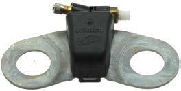
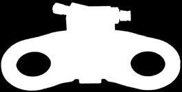


86 13 Tire Pressure Monitoring IVTM Integrated Vehicle Tire Pressure Monitoring 86

87 Tire Pressure Monitoring 13 87

88 13 Tire Pressure Monitoring IVTM (Integrated Vehicle Tire Monitoring System for commercial vehicles) stands for increased safety, mobility and economy. With the tire pressure monitor system IVTM for buses, which can be retrofitted at any time, you are automatically informed of pressure loss in the tires. IVTM increases safety Proper tires are a life insurance for driver, passengers, vehicle and load. With IVTM (Integrated Vehicle Tire Pressure Monitoring), WABCO provides a system that monitors the tire pressure in motor vehicles, towing vehicles or buses permanently using direct means of measurement. Research results Tire defects are the most common reason for commercial vehicle downtime. In 2011 an ADAC study estimated that over 30 % of commercial vehicles breakdowns were caused by tire failure. Around 85 % of punctures are caused by a creeping pressure loss, however, that normally goes unnoticed by the driver, particularly in commercial vehicles. IVTM identifies these pressure losses and warns the driver in due time - long before the tire suddenly bursts. IVTM effectively helps prevent accidents caused by serious tire damage and flat tire repairs in dangerous areas. Additionally, the system helps avoid unnecessary, and costly, vehicle downtime. A time-consuming installation of sensors in the rims is not required. Wheel modules, which are simply screwed on with the wheel nut, measure the pressure on the tire valves. The IVTM ECU is mounted on the vehicle chassis and receives the pressure data for all wheels via radio signal. The pressure for each tire can be retrieved for each tire from the driver s cabin. The display in the instrument panel warns the driver optically and acoustically of critical deviations from the defined nominal pressure. Many original equipment manufacturers enable the display for tire pressure information from IVTM in the vehicle s instrument panel. Product advantages and features Saving time and money. Benefits of IVTM: Increased traffic safety Fuel cost savings by ensuring optimum tire pressure and avoiding unnecessary rolling resistance 88


89 Tire Pressure Monitoring 13 Reduction in maintenance costs and tire damage due to insufficient tire pressure Increased tire life by driving with optimum tire pressure Ideal for retrofitting in buses Uncomplicated operation No need for time-consuming manual tire checks by personnel directly on the tire valve since the pressures of all tires can be displayed on the IVTM display Fast localisation and correction of operational and system faults by means of diagnostics memory The operating costs can be lowered by more than 600 Euro per bus and year using IVTM! * If it prevents only a single breakdown - and associated costs - the system will generally have paid for itself. Display of the relationship between tire pressure and fuel consumption - and tire service life Fuel consumption in percent tire pressure too low tire pressure too high Service life reduction in percent tire pressure too low tire pressure too high Tire pressure in percent Tire pressure in percent Functionality and components IVTM wheel module Wheel module For permanent monitoring of the tire pressure, each wheel is equipped with a wheel module mounted on the wheel bolts and a hose connection directly to the valve. The tires therefore do not have to be removed from the rim during wheel module installation. With a wheel or a tire change, the system does not have to be reconfigured. The wheel module contains a pressure sensor, the measured values of which are transferred at regulator intervals to the IVTM ECU (Electronic Control Unit) via a 433 MHz radio link. IVTM ECU In the electronics, an evaluation algorithm, which was especially designed for commercial vehicle tires by Michelin experts, detects all critical deviations from the set pressures of the tires. IVTM-ECU * Calculation applies for Solo bus 4 2 (6 tires) with an annual driving distance of 50,000 km. Presumed low pressure: 10 %. Fuel consumption: 35 liters over 100 km (price per liter 1.30 Euro). Tire mileage: 80,000 km (tire price 250 Euro). Manual tire pressure checks: every four weeks. Accepted maintenance costs: 30 Min. each 40 Euro per hour. 89
90 13 Tire Pressure Monitoring IVTM display The driver can be warned in due time of any critical pressure loss by the system through an IVTM display. The risk of a sudden flat tire is thus greatly reduced. IVTM display Device overview Display features: Acoustic warning Display of the faulty tire s position and its current pressure One ECU can monitor up to 12 wheel modules Integrated antenna in the ECU for proper reception of the pressure signals, even in 18 m articulated buses IVTM components (Example) Product number IVTM electronics IVTM display Rear axle wheel module Front axle wheel module Note: A large number of IVTM components are available covering the requirements of multiple tires sizes, rim types and vehicle configurations. IVTM sets are available for standard configurations such as solo-buses. Please ask your WABCO contact for more product information or for IVTM configuration assistance. We will be happy to provide an offer for retrofitting your vehicle with IVTM. Service and maintenance information Tips for the workshop IVTM is maintenance-free. Only when the display indicates a malfunction is troubleshooting via diagnostics necessary. All work on a wheel, hose and wheel module or tire pressure corrections must be carried out with the ignition OFF, otherwise a message will be entered in the ECU. A system reset is then performed automatically. Because of the external fastening of the wheel module on the wheel bolts, no new sensor needs be installed when changing tires. You only need to make sure that the wheel module is installed in the same position when changing a wheel or tire, i.e. on the same wheel bolt. With twin tires in particular, the correct allocation to the inner and outer wheel must be taken into account. With twin tires, the wheel modules must lie opposite one another (to prevent imbalance). With single tires, counterweights are installed accordingly. When removing the hose from the wheel module, contamination in the wheel module connection should be prevented. Check for damage to the O-rings of the plug-in connection when changing the hose. Replace defective O-rings as required. Valve connections must always be frictionless and not twisted. Hose brackets may need to be used in some cases. The hose position should be checked after replacing a tire. Check the seal on the valve and wheel module with leak detector spray if necessary. When using SuperSingle tires, such as Michelin X-One, tire pressure monitoring systems are specified by the vehicle manufacturer. 90

 with an annual operating distance of 50,000 km.")
91 Tire Pressure Monitoring 13 SEND YOUR BUSES on an economy drive! RETROFIT NOW AND SAVE MORE THAN 600 PER YEAR AND PER BUS WITH IVTM!* More time, lower costs: With WABCO s retrofit tire pressure monitoring system IVTM for buses, you can instantly see when tires begin to run low on air. It can save money and reduce operating costs by more than 600 per year and per bus!* WABCO IVTM an investment that pays off. Save maintenance costs Reduce fuel costs Longer tire service life Increased safety and mobility * Calculation for single 4 2 bus (6 tires) with an annual operating distance of 50,000 km. Estimated minimum pressure: 10 %. Fuel consumption: 35 litres per 100 km (price per litre 1.30). Tire performance: 80,000 km (price per tire 250). Manual tire pressure control: every four weeks. Estimated maintenance costs: 30 min at 40 per hour. Developed in co-operation with 91


92 14 Diagnostic Tools and Test Equipment Diagnostic Tools and Test Equipment 92
93 Diagnostic Tools and Test Equipment 14 93


94 14 Diagnostic Tools and Test Equipment While previously a separate test device was required for the diagnosis of each system on the bus, a PC or laptop with the corresponding Diagnostic Software is now sufficient for diagnosis. WABCO SYSTEM DIAGNOSIS WABCO Diagnostic Software For the diagnosis of WABCO components, WABCO has developed the System Diagnostic Software. This system diagnosis consists of special programs with extensive functions. The WABCO System Diagnosis allows you to perform a diagnosis on all electronic WABCO systems. The diagnosis software for electronic WABCO systems is offered, among other options, as an annual subscription. In this case, you will automatically receive all updates and software supplements and so you will always benefit from the latest developments in vehicle and safety technology. WABCO offers a special Diagnostic Software package for bus customers. It currently includes more than 20 system-related diagnostic programs. The most recent version of the programs can be downloaded from the internet any time and used immediately. Visit to purchase the Diagnostic Software Bus package. For a system diagnosis you need: the Toughbook laptop on which the WABCO Diagnostic Software is already installed or a commercially available PC or laptop the required WABCO Diagnostic Software the Diagnostic Interface Set connecting cable to vehicle electronics or diagnostic socket "Toughbook" laptop You can purchase all hardware components required for diagnosis from your WABCO partner. 94


95 Diagnostic Tools and Test Equipment 14 What do I need the PIN for? Testing devices and ancillary equipment Diagnostic Interface USB Diagnosis with the Diagnostic Software can be carried out by any user. If settings in electronic control units are to be changed, however, authorisation is required (PIN). The PIN verifies knowledge of the respective system and permits changing parameters in electronic units. You can obtain this PIN through relevant training at the WABCO Academy. Every participant in a system training course receives a PIN letter with his/ her purchased PINs. The PIN can be used to enable extended functions in the software and to define parameters in the electronic control units. When using the PIN, a so-called fingerprint is left in the diagnosed electronics, i.e. every change, especially regarding parameters, can be traced. The PIN is always person-related. This separates the company-related diagnostic software via the subscription number and person-related training. An employee can therefore change to another subsidiary and take his PIN data along with him/her. Diagnostic Interface Set The WABCO Diagnostic Interface Set is required to start a diagnosis of the electronic control unit. The set includes the Diagnostic Interface and an USB connecting cable to the PC or laptop. The vehicle connection on the Diagnostic Interface matches the connection for the Diagnostic Controller and earlier versions of the diagnostic interface, permitting the continued use of connecting cables used in the past. Diagnostic cable For the connection between the vehicle and the interface, WABCO offers various pre-fabricated diagnostic cables. Diagnostic accessory case Bus With this case - designed especially for the requirements of buses - you always have the most important connecting elements between the vehicle and your PC. Once the vehicle has been diagnosed, all cables can be stored in a manner where they are protected as well as easily identified. Diagnostic accessory case Bus Test case for compressed-air braking systems Calibrated test pressure gauges, connecting hoses and other parts of the test case enable quick and precise inspection of compressed-air braking systems according to the guidelines for performing safety tests on commercial vehicles. Test case for compressed-air braking systems 95

96 14 W.EASY Diagnostic solution for buses The only multi-brand diagnostic system for buses that integrates WABCO competence into a comprehensive solution. WABCOWÜRTH W.EASY With its innovative and modular solutions, WABCOWÜRTH makes diagnosis easy, transparent and efficient and efficient diagnostic systems get your business moving. An overview of the benefits provided by bus diagnosis Only W.EASY integrates the original WABCO system diagnosis in a single system. WABCO is one of the main suppliers for safety-relevant systems in buses. This is a great benefit to you in terms of safety, because only the original WABCO system diagnosis puts you in position to fully diagnose all WABCO systems. Visual vehicle selection and representation of the diagnostic sockets facilitates navigation and saves valuable time, thereby reducing any downtime. Broad manufacturer coverage: Evobus, MAN, Scania, Solaris, Volvo and many more The diagnostic solution for buses can be purchased as an independent bus diagnosis or in combination with the diagnosis for towing vehicles, trailers or light commercial vehicles. Reduced number of cables and adapters with integrated multiplexing technology. Our robust diagnostic trolley provides you with a clear, clean and ergonomic workplace for diagnosis. W.EASY is the only diagnostic system to offer genuine multitasking for convenient and more efficient diagnosis. The real-time display of various functions and information in up to four windows makes diagnosis clearer and saves valuable time. Regular updates always keep the system up-to-date. We can offer you the E-Learning course Electronic WABCO Systems specially for buses. Further WABCO training courses can also be booked. 96


97 W.EASY Diagnostic solution for buses 14 Hardware Panasonic Toughbook CF-53 laptop Diagnostic case Vehicle communication unit VCI with OBD cable, USB and Bluetooth capability Vehicle communication unit Diagnostic case Extensive selection of diagnostic cables and connection adapters for towing vehicles, trailers, light commercial vehicles and buses from various manufacturers Robust diagnostic trolley Accessories, e.g. printer Software We provide the software for buses of all major manufacturers. You can either use the complete licence or book the individual licences: Bus software package for multi-brand diagnosis and/or WABCO Bus Complete software package (towing vehicles, trailers, light commercial vehicles, buses) incl. WABCO complete package Comprehensive service, personalised advice Apart from out multi-brand diagnosis solution, we also offer extensive services, personal consultation, a product and vehicle technical hotline and user training. Since the requirements of our customers vary widely, we have made WABCOWÜRTH products both flexible and modular. With WABCOWÜRTH, all our customers get exactly what they want. Contact us: In close consultation with you we will put together the package of hardware, software and training modules that best suits your needs. WABCOWÜRTH is your reliable partner for commercial vehicle workshops uncomplicated, comprehensive and always available. More information can be found under 97


98 15 Services - Technical Training Technical Training and E-Learning 98
99 Services - Technical Training 15 99


100 15 Services - Technical Training For buses WABCO offers a number of special training courses on different subjects and of varying duration. TECHNICAL TRAINING Content: Structure and functionality of EBS-, ECAS-, ETS-, MTS-, IVTM- and ATC systems and their components Explanations of system structure and electronic circuit diagrams and control response Testing and troubleshooting with WABCO PC diagnosis Calibration of the ECAS system (setting the ride height) Descriptions of EBS, ECAS, MTS and ATC parameters in buses Note: After successfully completing the training, participants will receive a certificate. Having successfully participated in a system course, the participant receives on request the system-related PIN (personal identification number) so he or she can use the special diagnostic functions on WABCO systems for buses. 100


101 Services - Technical Training 15 E-LEARNING Knowledge and competence on the commercial vehicle market Web Based Training (WBT) this means computer-assisted learning when- and wherever you wish. All you need is a computer with internet access. Determine your own learning speed and save time and costs for travel and overnight stays. All courses are at the level of the latest technical developments. Even complex content is presented in an easily comprehensible manner using sound and images. Animations and video make learning diversified and interesting. Tasks, questions and a final test ensure successful learning. The courses are available in various languages. The prices are stated on the first page of the respective demo course. Order your access code (see WABCO part number) or pay online by credit card. You will find further details on E-Learning on the Internet on the WABCO Academy website at or directly at wabco.info. We offer training courses on the subjects ABS, EBS, electronic air suspension, tire pressure monitoring, disc brakes, basic knowledge of braking systems, telematics and WABCO electronic systems in buses. This programme is constantly expanded. Make use of the opportunity to test our demo versions before you decide on a course. Advantages of E-Learning: Complete course with completion test and PIN letter Simple, structured learning with interactive elements Personal time & course management Prerequisites for participation are: Computer with audio, headphones if possible Internet access via ISDN, DSL (recommended) Personal address 101


102 16 More Information WHERE CAN I OBTAIN MORE INFORMATION Online product catalogue INFORM The online product catalogue INFORM provides you with convenient access to the complete technical documentation: product data sheets, outline drawings, cross references, vehicle applications, repair notes and wiring diagrams. Open our website wabco-auto.com Click the INFORM link in the Quick Access Links box. Technical documents in many different languages The technical publications describe the functions of systems and components as well as installation, retrofitting and diagnosis: System descriptions Catalogues Installation / Maintenance instructions Diagnostics documentations Posters All brochures are available in PDF format from the INFORM product catalogue. Please contact your WABCO partner for printed versions. Your direct contact to WABCO In addition to our online services, trained members of staff are there to help you in our WABCO Service Centres to directly answer any technical or business-related questions you may have. Contact us if you need assistance: Find the right product Diagnostics support Training System support Order management Your will find your WABCO partners on the internet at com. In the Quick Access Links box, click on Service Partner Locations ( 102


103 More Information 16 GENUINE WABCO PARTS OFFER RELIABLE PROTECTION Choose genuine WABCO parts Genuine WABCO parts are made of high quality materials and are rigorously tested before they leave our factories. You also have the assurance that the quality of every WABCO product is reinforced by a powerful customer service network. Because WABCO, as a tier one supplier, works with the world s leading Original Equipment Manufacturers, WABCO has the experience and scale to meet the most accurate production standards. The quality of every genuine WABCO part is supported by: Tooling made for serial production Regular sub-supplier audits Exhaustive end-of-line tests Quality standards below 50 PPM (parts per million defects) A genuine WABCO part is as unique as your fingerprint. Accept no substitute. WABCO reassurance The package you will get with a genuine WABCO part: 24 month product warranty Overnight delivery Technical support from WABCO Professional training solutions from the WABCO Academy Access to diagnostics tools and support from the WABCO Service Partner network Straightforward claims handling Plus, of course, the confidence that the Original Equipment Manufacturers rigorous quality standards are met. Installing copy parts can cost lives genuine WABCO parts protect your business. WABCO Service Partner WABCO Service Partners the network you can rely on. You can access 2,000 high quality workshops with more than 6,000 specialist mechanics, all trained to WABCO s exacting standards and equipped with our most upto-the-minute systems diagnostic and support technology. 103

104 When purchasing a WABCO product, please make sure it has the typical WABCO product marks (particularly on packaging, labels and identification plate) as evidence that it is an original WABCO part. In case you have any doubts, please contact your WABCO sales partner. WABCO (NYSE: WBC) is a leading global supplier of technologies and control systems for the safety and efficiency of commercial vehicles. Founded nearly 150 years ago, WABCO continues to pioneer breakthrough electronic, mechanical and mechatronic technologies for braking, stability and transmission automation systems supplied to the world s leading commercial truck, bus and trailer manufacturers. WABCO is headquartered in Brussels, Belgium. For more information, visit WABCO All rights reserved / DEALER
capacity due to increased traction; particularly advantageous on road surfaces
 42-800 Design and function of acceleration slip control (ASR I) A. General B. Driving with ASR I C. Overall function of ASR I D. Location of components E. Individual functions A. General The acceleration
Starting up hydraulic systems
 General / Installation A hydraulic system that operates economically, safely, and trouble-free requires careful planning, as well as proper installation and start-up. Conscientious maintenance has a considerable
Chapter 33 Fundamentals of Hydraulic and Air-Over-Hydraulic Braking Systems
 Chapter 33 Fundamentals of Hydraulic and Air-Over-Hydraulic Braking Systems Introduction Vehicle s braking system must meet the following requirements: To adequately and safely reduce a vehicle s speed,
EBS IN TOWING VEHICLES AND BUSES SYSTEM DESCRIPTION
 EBS IN TOWING VEHICLES AND BUSES SYSTEM DESCRIPTION EBS in towing vehicles and buses System Description 3rd edition This publication is not subject to an updating service. New versions can be found in
SUBJECT: Automatic Stability Control with Traction Control System (ASC+T)
") Group 34 34 01 90 (2105) Woodcliff Lake, NJ October 1990 Brakes Service Engineering -------------------------------------------------------------------------------------------------------- SUBJECT: Automatic
Group 34 34 01 90 (2105) Woodcliff Lake, NJ October 1990 Brakes Service Engineering -------------------------------------------------------------------------------------------------------- SUBJECT: Automatic
2006 Mercedes-Benz USA, LLC. Chassis and Drivetrain 42
 Page 1 of 5 Chassis and Drivetrain 42 Brakes Anti-lock Brake System (ABS) 4-Wheel Electronic Traction Control System (4-ETS) Electronic Brake Proportioning (EBP) System Description The hydraulic pressure
ABS, 4-ETS and EBP BRAKES ANTI-LOCK BRAKE SYSTEM (ABS) 4-WHEEL ELECTRONIC TRACTION CONTROL SYSTEM (4-ETS) ELECTRONIC BRAKE PROPORTIONING (EBP)
 4-WHEEL ELECTRONIC TRACTION CONTROL SYSTEM (4-ETS) ELECTRONIC BRAKE PROPORTIONING (EBP)") 1 of 9 4/27/2008 7:52 AM Home Account Contact ALLDATA Log Out Help Select Vehicle New TSBs Technician's Reference Component Search: METRO TOYOTA OK 2002 Mercedes Benz Truck ML 320 (163.154) V6-3.2L (112.942)
1 of 9 4/27/2008 7:52 AM Home Account Contact ALLDATA Log Out Help Select Vehicle New TSBs Technician's Reference Component Search: METRO TOYOTA OK 2002 Mercedes Benz Truck ML 320 (163.154) V6-3.2L (112.942)
Module 11: Antilock Brakes Systems
 ÂÂ ABS Brake System Antilock Brake System Operation Principles of ABS Braking ABS Master Cylinder Hydraulic Control Unit Wheel Speed Sensors ABS Electronic Control Unit Terms and Definitions Purposes for
The electro-mechanical power steering with dual pinion
 Service Training Self-study programme 317 The electro-mechanical power steering with dual pinion Design and function The electro-mechanical power steering has many advantages over the hydraulic steering
HECU Clock frequency 32 MHz 50 MHz Memory 128 KB 512 KB Switch Orifice Orifice. Operating temperature - 40 C to 150 C - 40 C to 150 C
 489000 113 1. SPECIFICATION Unit Description Specification ABS ESP HECU Clock frequency 32 MHz 50 MHz Memory 128 KB 512 KB Switch Orifice Orifice Wheel speed sensor ABS / ESP CBS Operating temperature
SCANIA K-SERIES. Great buses and coaches start here
 SCANIA K-SERIES Great buses and coaches start here SCANIA K-SERIES 2 3 Great buses and coaches, from the ground up Take a close look at the chassis. It s a crucial foundation. By building on Scania quality,
Electromechanical Steering with Parallel-axis Drive
 Service Training Self-study Programme 399 Electromechanical Steering with Parallel-axis Drive Design and Function The electromechanical power steering has many advantages compared with a hydraulic steering
Exhaust System - 2.2L Diesel
 Page 1 of 9 Published: Mar 8, 2007 Exhaust System - 2.2L Diesel COMPONENT LOCATION - WITH DIESEL PARTICULATE FILTER Item Part Number Description 1 Exhaust manifold (ref only) 2 Pressure differential sensor
ABS keeps the vehicle steerable, even during an emergency braking
 ABS keeps the vehicle steerable, even during an emergency braking under all road conditions 1 Contents! Safety systems in vehicles! Why do you need ABS?! How does ABS work?! What are the benefits of ABS?!
PRODUCT CATALOGUE. PRODUCTS and SOLUTIONS for Commercial Vehicles. APPLICATIONS for Vehicle Manufacturing. ORIGINAL QUALITY for Repair
 PRODUCT CATALOGUE PRODUCTS and SOLUTIONS for Commercial Vehicles APPLICATIONS for Vehicle Manufacturing ORIGINAL QUALITY for Repair PRODUCT CATALOGUE Edition 2 This publication is not subject to any update
SYSTEM SAVER 318 AIR COMPRESSOR FOR MACK E-TECH AND ASET ENGINES MAINTENANCE MANUAL
 SYSTEM SAVER 318 AIR COMPRESSOR FOR MACK E-TECH AND ASET ENGINES MAINTENANCE MANUAL NON-THROUGH DRIVE THROUGH DRIVE Service Notes About This Manual This manual provides service and repair procedures for
Accident Avoidance Technologies
 Accident Avoidance Technologies Quentin Hall District Manager Meritor, Inc. 1721 Dryden Drive Spring Hill, TN 37174 Cell: 317-408-9741 Email: Quentin.Hall@Meritor.com Agenda Mechanical Items RSC (Roll
Overview. KNOTT brakes overview The basics for around 2000 solutions BRAKES. We make your brake
 Overview BRAKES KNOTT brakes overview The basics for around 2000 solutions www.knott.de We make your brake KNOTT develops and produces individual brake solutions for all branches: from agriculture and
To study about various types of braking system.
 To study about various types of braking system INTRODUCTION The system is purely mechanical means & is independent of the hydraulic system which controls the brake normally. A brake commonly referred to
INSTRUCTIONS FOR: VACUUM TESTER AND BRAKE BLEEDING KIT
 INSTRUCTIONS FOR: VACUUM TESTER AND BRAKE BLEEDING KIT MODEL: VS402 Thank you for purchasing a Sealey product. Manufactured to a high standard this product will, if used according to these instructions
Hybrid Architectures for Automated Transmission Systems
 1 / 5 Hybrid Architectures for Automated Transmission Systems - add-on and integrated solutions - Dierk REITZ, Uwe WAGNER, Reinhard BERGER LuK GmbH & Co. ohg Bussmatten 2, 77815 Bühl, Germany (E-Mail:
Regeneration of the Particulate Filter by Using Navigation Data
 COVER STORY EXHAUST AFTERTREATMENT Regeneration of the Particulate Filter by Using Navigation Data Increasing connectivity is having a major effect on the driving experience as well as on the car s inner
6-speed automatic transmission E60, E53. VS-22 je Baugruppe/Group: (040) 09/2003. Introduction
 09/2003. Introduction") VS-22 je Baugruppe/Group: 24 24 01 03 (040) 6-speed automatic transmission E60, E53 weltweit Datum/Date: 09/2003 Introduction The 6-speed automatic transmissions GA6HP19Z and GA6HP26Z have been jointly
VS-22 je Baugruppe/Group: 24 24 01 03 (040) 6-speed automatic transmission E60, E53 weltweit Datum/Date: 09/2003 Introduction The 6-speed automatic transmissions GA6HP19Z and GA6HP26Z have been jointly
DRIVER SAFETY AND WELL - BEING
 DRIVER SAFETY AND WELL - BEING AT KENWORTH, PROTECTING THE DRIVER, VEHICLE, PAYLOAD AND OTHER ROAD USERS AGAINST UNEXPECTED HAZARDS, HAS ALWAYS BEEN A PARAMOUNT CONSIDERATION Ease of operation and the
OnGuard Display Operating Instructions
 Issued 09-09 Technical Bulletin Issued 1 Technical 09-09 Bulletin OnGuard Display Operating Instructions Hazard Alert Messages Read and observe all Warning and Caution hazard alert messages in this publication.
Servo-pneumatic drive solution for welding guns. Top quality welding!
 Servo-pneumatic drive solution for welding guns Sturdy and precise! Top quality welding! Highlights Extremely short cycle times High quality and outstanding reproducibility of the spot welds Excellent
Anticipated Changes in the Heavy Duty Remanufacturing Industry
 Anticipated Changes in the Heavy Duty Remanufacturing Industry Joe Kripli APRA President APRA Founded in 1941. The scarcity of automotive & truck parts during World War II helped the industry grow. Today
The European Commission s science and knowledge service. Joint Research Centre. VECTO - Overview VECTO Workshop Ispra, November, 2018
 The European Commission s science and knowledge service Joint Research Centre VECTO - Overview 2018 VECTO Workshop Ispra, November, 2018 Content Background Overview VECTO method Simulation tool Component
Supplier Day 2012 R&D Presentation
 Supplier Day 2012 R&D Presentation What Do We Do? We Stop Trucks Innovative Vehicle Solutions 2 Product Overview Air Management Brake Control Air dryer systems Air cleaner systems ABS EBS Valves Brake
To give you a better understanding of the tasks and functions of ABS, we will first look at the physics principles.
 489201 103 SYSTEM 489201 1. GENERAL INFORMATION The aim of the is to mmaintain steerability and driving stability and to take the burden off the driver. If the stopping distance is shorter on some road
Horse power on the road. More efficiency for transporting cars.
 Horse power on the road. More efficiency for transporting cars. Getting cars moving. Not a kilometre on the clock and already purring along. Whether cars have to be transported in open or closed bodies,
Trailer brake and chassis control
 COMMERCIAL VEHICLE SYSTEMS BRAKE AND CHASSIS CONTROL Trailer brake and chassis control TRAILER COMPETENCE 2 THE MUNICH-BASED KNORR-BREMSE GROUP IS THE WORLD S LEADING MANUFACTURER OF BRAKING SYSTEMS FOR
FACT SHEET. I-Shift software package. Volvo Trucks. Driving Progress
 Volvo Trucks. Driving Progress FACT SHEET The I-Shift gearbox s functions are optimised with specially adapted software packages that make the gearbox even more practical and economical by adapting the
Vibration damper control
 Vibration damper control The damper control system registers the condition of the road surface and the movements of the vehicle via four wheel acceleration sensors and three body acceleration sensors.
TECHNICAL PAPER 1002 FT. WORTH, TEXAS REPORT X ORDER
 I. REFERENCE: 1 30 [1] Snow Engineering Co. Drawing 80504 Sheet 21, Hydraulic Schematic [2] Snow Engineering Co. Drawing 60445, Sheet 21 Control Logic Flow Chart [3] Snow Engineering Co. Drawing 80577,
VEHICLE DYNAMICS CONTROL (VDC)
") VEHICLE DYNAMICS CONTROL (VDC) SYSTEM 1. Vehicle Dynamics Control (VDC) System A: GENERAL The vehicle dynamics control (VDC) system is a driver assist system which enhances vehicle s running stability
VEHICLE DYNAMICS CONTROL (VDC) SYSTEM 1. Vehicle Dynamics Control (VDC) System A: GENERAL The vehicle dynamics control (VDC) system is a driver assist system which enhances vehicle s running stability
MECA0063 : Braking systems
 MECA0063 : Braking systems Pierre Duysinx Research Center in Sustainable Automotive Technologies of University of Liege Academic Year 2018-2019 1 Bibliography T. Gillespie. «Fundamentals of vehicle Dynamics»,
Relax and enjoy the drive You re in control. Unit G, 2 Hudson Ave, Castle Hill NSW
 AN INTRODUCTION TO THE COMMAND AUTO GROUP The Command Auto Group has distributed Cruise Controls to Australian consumers and Professional Installers for over 20 years. Should you require sales or technical
distribution An automatic solution to enhancing productivity, profitability and environmental performance ALLISON TRANSMISSION EUROPE
 distribution ALLISON TRANSMISSION EUROPE ALLISON TRANSMISSION EUROPE B.V BAANHOEK 188 3361 GN SLIEDRECHT THE NETHERLANDS T. +31 (0)786 422 100 F. +31 (0)786 152 587 ALLISONTRANSMISSION.COM SA 4107EN (2003/05)
Steering unit LAGC. Data sheet
 Steering unit LAGC Data sheet Nominal sizes Series Maximum flow HE 14365 / 09.2017 40 1000 1 x and 2 x 80 l / min 2 LAGC HE 14365 / 09.2017 Page Content 4 4 5 6 7 8 9 10 11 12 13 14 Features Ordering details
1. ENGINE ECU AND OTHER COMPONENTS
 09-3 EGINE CONTROL SYSTEM 1. ENGINE ECU AND OTHER COMPONENTS ECU/Barometric Sensor Camshaft Position Sensor HFM Sensor / Intake Air Temperature Sensor Fuel Filter (Water Sensor) Preheating Relay Accelerator
200C II BRAKE SYSTEM
 200C II BRAKE SYSTEM The braking system on the 200C II Kress Coal Hauler uses hydraulic oil pressure from both the System and Steering accumulator circuits. Using oil from both circuits provides braking
GF42.47-P-0001FLM Adaptive brake (ABR), function
, function") GF42.47-P-0001FLM Adaptive brake (ABR), function 14.1.13 MODEL 212 (except 212.095/098/298) as of model year 2014 Function requirements, general the engine is running or has been switched off by the ECO
GF42.47-P-0001FLM Adaptive brake (ABR), function 14.1.13 MODEL 212 (except 212.095/098/298) as of model year 2014 Function requirements, general the engine is running or has been switched off by the ECO
VEHICLE INFORMATION LEAFLET 2.0
 VEHICLE INFORMATION LEAFLET 2.0 KEY WABCO SPARE PARTS FOR VOLVO VEHICLES KEY WABCO SPARE PARTS FOR VOLVO VEHICLES CONTENT KEY WABCO SPARE PARTS FOR VOLVO VEHICLES ABS pneumatic - Repair Solution... 3 Air
OLYMPUS. Gas Turbine Fuel Controls. Building of complete custom designed fuel systems. Single or serial production quantities
 OLYMPUS Gas Turbine Fuel Controls Gas Fuel Throttle Valve Liquid Fuel Throttle Valve Liquid Fuel Metering Pump Gas & Liquid Fuel Throttle Assemblies Building of complete custom designed fuel systems Single
AUSTRALIAN MADE. WORLD S BEST.
 KENWORTH SAFETY BY DESIGN You can feel secure in the knowledge the extensive testing, innovation and application engineering behind every Kenworth truck will deliver real peace of mind, on the road and
 Page 1 of 23 593: Brake control system V70 (00-08), 2004, B5244S2, M56, L.H.D, YV1SW65S241436824, 436824 16/7/2018 PRINT 593: Brake control system ABS control ABS function Active yaw control Active yaw
Steering unit LAGZ. Data sheet. Series 2 x
 Steering unit LAGZ Data sheet Nominal sizes 125 620 Series 2 x Maximum flow 50 l / min HE 11868 / 09.2017 2 LAGZ HE 11868 / 09.2017 Page Content 4 4 5 6 7 8 9 10 11 12 13 14 Features Ordering details Function,
ProVent MANN+HUMMEL Oil Separator for Closed and Open Crankcase Ventilation
 ProVent MANN+HUMMEL Oil Separator for Closed and Open Crankcase Ventilation ProVent high performance with distinct advantages ProVent is MANN+HUMMEL's newest innovation for crankcase ventilation. It is
MANN+HUMMEL ProVent. Oil separator for closed and open crankcase ventilation
 MANN+HUMMEL ProVent Oil separator for closed and open crankcase ventilation ProVent high performance with distinct advantages The development of the whole MANN+HUMMEL ProVent product family was directed
Original Language Version VS4021 Issue: 1-08/06/12
 1. safety instructions Keep this product in good working order and condition, take immediate action to repair or replace damaged parts. Use approved parts only. Unapproved parts will invalidate the warranty.
ZF Mitigates Rear-End Collisions with New Electronic Safety Assistant for Trucks
 Page 1/6, 2016-06-29 ZF Mitigates Rear-End Collisions with New Electronic Safety Assistant for Trucks The Evasive Maneuver Assist (EMA), developed with project partner WABCO, automatically steers tractor-trailers
1. BRAKE SYSTEM GENERAL INFORMATION
 4890-01 08-3 1. BRAKE SYSTEM GENERAL INFORMATION Front Disc 1) FRONT BRAKE For the front brake system, the ventilated disc type is applied regardless of the ABS/ system installation. Two 43 mm diameter
FUSO Genuine Parts and Accessories
 FUSO Genuine Parts and Accessories FUSO Genuine Parts and Accessories Engineered by FUSO with passion and precision just like your truck, to give you the best in quality & reliability. This means you can
We Make IT EASY! Maintenance and repair program by Fuso.
 We Make IT EASY! Maintenance and repair program by Fuso. Fuso is a large, well established global truck and bus brand. Our vehicles have been sold and supported in Australia for over 40 years by our national
High Speed. Low Speed F - R. Auxiliary Hydraulics. Lock. Neutral
 Articulation and Frame Oscillation Our wheel loaders are most often operated in heavy terrain and we include the features for top performance. Articulation allows the rear tires to follow the same track
35C-1 GROUP 35C CONTENTS FEATURES... 35C-2 SYSTEM OPERATION... 35C-16 CONSTRUCTION DESCRIPTION... 35C-5
 35C-1 GROUP 35C CONTENTS FEATURES.................... 35C-2 SYSTEM OPERATION............ 35C-16... 35C-5 35C-2 FEATURES Anti-skid Brake System/Active Stability System (ABS/active stability system) is available
The electromechanical parking brake
 Service Training Self-study programme 346 The electromechanical parking brake Design and function To make absolutely sure that the vehicle could not roll away when parked up, the driver had to pull up
SECTION 4A BRAKE SYSTEM TABLE OF CONTENTS
 SECTION 4A BRAKE SYSTEM TABLE OF CONTENTS Description and Operation... 4A-2 Braking System Testing... 4A-2 Hydraulic Brake System... 4A-2 Brake Pedal... 4A-2 Master Cylinder... 4A-2 Brake Booster... 4A-3
OFF-HIGHWAY OVERVIEW TECHNOLOGIES AND PRODUCTS
 OFF-HIGHWAY OVERVIEW TECHNOLOGIES AND PRODUCTS OFF-HIGHWAY OVERVIEW TECHNOLOGIES AND PRODUCTS Edition 2 This publication is not subject to any update service. You will find the current version on the
EMC-HD. C 01_2 Subheadline_15pt/7.2mm
 C Electromechanical 01_1 Headline_36pt/14.4mm Cylinder EMC-HD C 01_2 Subheadline_15pt/7.2mm 2 Elektromechanischer Zylinder EMC-HD Short product name Example: EMC 085 HD 1 System = ElectroMechanical Cylinder
Laird Thermal Systems Application Note. Cooling Solutions for Automotive Technologies
 Laird Thermal Systems Application Note Cooling Solutions for Automotive Technologies Table of Contents Introduction...3 Lighting...3 Imaging Sensors...4 Heads-Up Display...5 Challenges...5 Solutions...6
With Every Delivery, An Allison Lowers Your Ownership Costs. Distribution Applications
 With Every Delivery, An Allison Lowers Your Ownership Costs Distribution Applications Proven Reliability Lower Total Cost Of Ownership Exceptional Fuel Economy Low Maintenance Carry A Lower Total Cost
VARIABLE PUMPS FOR CLOSED LOOP OPERATION type HV-02
 Design characteristics 1-control device modular design, precise and load-independent 2-swash plate hydrostatic bearing 3-piston-slipper assembly 21 swash angle 4-housing monoshell for high rigidity 5-valve
Original Operating Manual
 2010-10-29 Original Operating Manual Control Panel Comfort for Pedelecs Series 4313 Save for future use! Marquardt GmbH Schlossstraße 16 78604 Rietheim-Weilheim E-mail: marquardt@marquardt.de Website:
VS403 INSTRUCTIONS FOR: VACUUM AND PRESSURE TEST / BRAKE BLEEDING UNIT MODEL: SAFETY INSTRUCTIONS INTRODUCTION & CONTENTS. fig.1
 INSTRUCTIONS FOR: VACUUM AND PRESSURE TEST / BRAKE BLEEDING UNIT MODEL: VS403 Thank you for purchasing a Sealey product. Manufactured to a high standard this product will, if used according to these instructions
ANTI-LOCK BRAKE SYSTEM - REAR WHEEL
 ANTI-LOCK BRAKE SYSTEM - REAR WHEEL 1994 Nissan Pickup 1994 BRAKES Nissan - Rear Anti-Lock Pathfinder, Pickup DESCRIPTION In 2WD mode, Rear Anti-Lock Brake System (RABS) helps the driver to maintain steering
1. Anti-lock Brake System (ABS)
") W1860BE.book Page 2 Tuesday, January 28, 2003 11:01 PM 1. Anti-lock Brake System () A: FEATURE The 5.3i type used in the Impreza has a hydraulic control unit, an control module, a valve relay and a motor
W1860BE.book Page 2 Tuesday, January 28, 2003 11:01 PM 1. Anti-lock Brake System () A: FEATURE The 5.3i type used in the Impreza has a hydraulic control unit, an control module, a valve relay and a motor
Mercedes-Benz Service. Brake System Modifications and New Features Model 374, 375, , , ,
 Mercedes-Benz Service Brake System Modifications and New Features Model 374, 375, 930-934, 940-944, 950-954, 970-976 Mercedes-Benz Service Brake System Modifications and New Features Model 374, 375, 930-934,
Meritor WABCO Antilock Braking System (ABS) 42.06
 42.06") Meritor WABCO Antilock Braking System (ABS) 4.06 Control Valve Replacement Replacement NOTE: Wire repairs may require the use of special tools for certain connectors and terminals. See Group 54 for information
Meritor WABCO Antilock Braking System (ABS) 4.06 Control Valve Replacement Replacement NOTE: Wire repairs may require the use of special tools for certain connectors and terminals. See Group 54 for information
Multi-ECU HiL-Systems for Virtual Characteristic Rating of Vehicle Dynamics Control Systems
 Multi-ECU HiL-Systems for Virtual Characteristic Rating of Vehicle Dynamics Control Systems Dipl.-Ing. Ronnie Dessort, M.Sc. Philipp Simon - TESIS DYNAware GmbH Dipl.-Ing. Jörg Pfau - Audi AG VDI-Conference
44.3 kw (59.4 HP) at 2100 rpm kg mm DX85R-3. Compact Excavator
 at 2100 rpm kg mm DX85R-3. Compact Excavator") 44.3 kw (59.4 HP) at 2100 rpm 8540-8600 kg 4175-4725 mm DX85R-3 Compact Excavator All-round versatility and improved fuel efficiency Whatever your application you can rely on the DX85R-3 ideal working
44.3 kw (59.4 HP) at 2100 rpm 8540-8600 kg 4175-4725 mm DX85R-3 Compact Excavator All-round versatility and improved fuel efficiency Whatever your application you can rely on the DX85R-3 ideal working
Transmitted by the expert from Germany
 Overview Transmitted by the expert from Germany Informal document No. GRRF-62-17 (62nd GRRF, 25-28 September 2007, agenda item 9(f)) TPMS Motivations Principles of tire pressure monitoring systems (TPMS)
System overview. Introduction. Copyright 2004 Volvo Car Corporation. All rights reserved.
 "VCC141172 EN 20090206" 1(40) System overview Introduction The Mark25 brake control system The Mark 25 brake control system with the brake control module (BCM) is an electronic control system which prevents
Conventional Cruise Control
 About Conventional Cruise Control Conventional Cruise Control Conventional Cruise Control is a driving support system intended to allow more comfortable driving on expressways, freeways and interstate
time for smarter solutions scania heavy tipper
 time for smarter solutions scania heavy tipper We provide a framework of people, methods, tools and information to increase productivity, reduce costs and manage risks better in mining operations. 2 Scania
ABS Operator s Manual
 ABS Operator s Manual Bendix Antilock Brake Systems With optional advanced antilock braking features: Automatic Traction Control (ATC) and RSP Roll Stability System Read, understand and follow the information
26 - COOLING SYSTEM CONTENTS ENGINE COOLING - DESCRIPTION... 3 ENGINE COOLING - OPERATION... 9 COOLING SYSTEM FAULTS... 1
 26 - COOLING SYSTEM CONTENTS Page LAND ROVER V8 DESCRIPTION AND OPERATION ENGINE COOLING - DESCRIPTION... 3 ENGINE COOLING - OPERATION... 9 FAULT DIAGNOSIS COOLING SYSTEM FAULTS... 1 REPAIR COOLANT - DRAIN
Volvo 7900 HYBRID. The complete single deck choice for fuel efficiency and reliability
 Volvo 7900 HYBRID The complete single deck choice for fuel efficiency and reliability The Volvo 7900 Hybrid takes green efficiency to the next level, far beyond Euro 6 legislation. It s delivering significant
INTELLIGENT TECHNOLOGY SIMPLIFIES OPERATION AND IMPROVES PERFORMANCE
 TRANSMISSIONS INTELLIGENT TECHNOLOGY SIMPLIFIES OPERATION AND IMPROVES PERFORMANCE PACCAR s automated transmission comes with a suite of impressive technology features designed to make it easier to deliver
4 fuel-efficient driving
 4 fuel-efficient driving This chapter focuses on fuel-efficient driving techniques for large dieselpowered commercial vehicles. Many of these techniques can also be applied to smaller commercial vehicles
PREVOST AIR SYSTEMS WHAT THEY DO AND HOW THEY DO IT
 PREVOST AIR SYSTEMS WHAT THEY DO AND HOW THEY DO IT Air. In our buses we use air for many purposes. We warm ourselves and cool ourselves with it. We supply it to our engines so they will run. Air is what
Tips & Technology For Bosch business partners
 Tips & Technology For Bosch business partners Current topics for successful workshops No. 05 Trucks Starters and starter systems Part 2 Moderately heavy commercial vehicles with diesel engines having a
Release Notes. Scania Diagnos & Programmer 3 Version 2.28
 en-gb Release Notes Scania Diagnos & Programmer 3 Version 2.28 Version 2.28 replaces version 2.27 of Scania Diagnos & Programmer 3 and supports the systems for vehicles in the P, G, R, S and T series,
Driver Instructions. Hydraulic Launch Assist (HLA ) TRDR1200
 TRDR1200") Driver Instructions Hydraulic Launch Assist (HLA ) TRDR1200 September 2011 Table of Contents Warnings and Cautions Definitions... 1 Driver Display Module... 7 Operation... 9 Service and Maintenance...
Driver Instructions Hydraulic Launch Assist (HLA ) TRDR1200 September 2011 Table of Contents Warnings and Cautions Definitions... 1 Driver Display Module... 7 Operation... 9 Service and Maintenance...
How do we make city buses cleaner and more comfortable?
 How do we make city buses cleaner and more comfortable? With the intelligent and leading edge ELFA hybrid drive system Answers for industry. Economical, ecological and efficient: The intelligent response
Modern Auto Tech Study Guide Chapters 71 & 73 Pages Brake Systems 49 Points. Automotive Service
 Modern Auto Tech Study Guide Chapters 71 & 73 Pages 1369 1444 Brake Systems 49 Points 1. Automotive systems use to stop, slow or to hold the wheels from turning. Brake, Friction Brake, Fraction Brake,
Valve Accessories. Limit switches, solenoid valves, lock-up valves, supply pressure regulators, volume boosters, quick exhaust valves, applications
 Valve Accessories Limit switches, solenoid valves, lock-up valves, supply pressure regulators, volume boosters, quick exhaust valves, applications SMART IN FLOW CONTROL. Our expertise for you Competence
definition Retarders definition driving tip chapter 2 heavy vehicle braking Using retarders
 chapter 2 heavy vehicle braking Brake fade occurs when your brakes stop working properly because they're overheated. Your vehicle takes longer to stop, or may not stop at all if you haven't properly controlled
SHELL NATURELLE CHANGEOVER ADVICE
 SHELL NATURELLE CHANGEOVER ADVICE Bulletin, 1 January 2018 This bulletin is issued to all customer vessels and shore-based staff to help manage and plan the conversion to the Shell Naturelle range of lubricants.
Introduction and Overview to Friction Brakes. Course 105 PREVIEW ONLY PARTICIPANT GUIDE
 Introduction and Overview to Friction Brakes Course 105 PARTICIPANT GUIDE Table of Contents How to Use the Participant Guide... ii MODULE 1...1 General Principles and Terminology...1 1-1 Safety Review...2
INTRODUCING THE LATEST ADVANCEMENT IN AUTOMATED TRANSMISSIONS
 TRANSMISSIONS INTRODUCING E LATEST ADVANCEMENT IN AUTOMATED TRANSMISSIONS Designed from the ground up to work seamlessly with PACCAR MX engines and axles, the new 12-speed automated transmission completes
Sorting Line with Detection 24V
 536633 Sorting Line with Detection 24V I2 Q2 I4 I3 I1 Coupling to multi processing station I5 I6 I7 Not in the picture: Q1, Q3, Q4, Q5 Circuit layout for Sorting Line with Detection Terminal no. Function
B60W. Definition statement. Relationships with other classification places CPC - B60W
 B60W CONJOINT CONTROL OF VEHICLE SUB-UNITS OF DIFFERENT TYPE OR DIFFERENT FUNCTION; CONTROL SYSTEMS SPECIALLY ADAPTED FOR HYBRID VEHICLES; ROAD VEHICLE DRIVE CONTROL SYSTEMS FOR PURPOSES NOT RELATED TO
Delomatic 400 (DM 400) based Gas Engine and Combined Heat and Power (CHP) Control and Management System
 based Gas Engine and Combined Heat and Power (CHP) Control and Management System") Table of contents 1. WARNINGS AND LEGAL INFORMATION... 3 3.5 LEGAL INFORMATION AND RESPONSIBILITY... 3 3.6 ELECTROSTATIC DISCHARGE AWARENESS... 3 3.7 SAFETY ISSUES... DELOMATIC 400 GAS 3 3.8 DISCLAIMER...
Table of contents 1. WARNINGS AND LEGAL INFORMATION... 3 3.5 LEGAL INFORMATION AND RESPONSIBILITY... 3 3.6 ELECTROSTATIC DISCHARGE AWARENESS... 3 3.7 SAFETY ISSUES... DELOMATIC 400 GAS 3 3.8 DISCLAIMER...
HPB Hydraulic Power Braking System
 HPB Hydraulic Power Braking System 4 th Edition This publication is not subject to any update service. New versions are available in INFORM at www.wabco-auto.com Copyright WABCO 2007 Vehicle Control Systems
N G 3 S p r i n g B r a k e s
 C o m m e r c i a l V e h i c l e S y s t e m s P r o d u c t M a n u a l N G 3 S p r i n g B r a k e s R ationalised Units for S-Cam Applications P r o d u c t M a n u a l Disclaimer The information contained
In 04/2000, active cruise control (system supplier: BOSCH) was installed for the first time in a BMW as special equipment for the E38.
 was installed for the first time in a BMW as special equipment for the E38.") 10/20/2015 1/10 FTD-FTD-SBT2004-660104067 Active Cruise Control E60, E61, E63, E64, E65, E66 VIN: XXXXXXX Vehicle: 7'/E65/SEDAN/750i/N62/AUTO/USA/LL/2007/06 System Version: 3.47.10.13054 Data Version:
10/20/2015 1/10 FTD-FTD-SBT2004-660104067 Active Cruise Control E60, E61, E63, E64, E65, E66 VIN: XXXXXXX Vehicle: 7'/E65/SEDAN/750i/N62/AUTO/USA/LL/2007/06 System Version: 3.47.10.13054 Data Version:
Volkswagen DCC Adaptive Chassis Control - Design and Function DCC Adaptive Chassis Control. Basics of the damping system
 Volkswagen DCC Adaptive Chassis Control - Design and Function DCC Adaptive Chassis Control The rule for suspension systems has always been that increasing sportiness compromises the ride. In this new system
IVTM Installation Manual
 Integrated Vehicle Tire Pressure Monitoring IVTM Installation Manual 2nd edition Copyright WABCO 2006 Vehicle Control Systems An American Standard Company The right of amendment is reserved Version 002/06.06(us)