MECA0063 : Braking systems
|
|
|
- Barbra Spencer
- 5 years ago
- Views:
Transcription
1 MECA0063 : Braking systems Pierre Duysinx Research Center in Sustainable Automotive Technologies of University of Liege Academic Year
2 Bibliography T. Gillespie. «Fundamentals of vehicle Dynamics», 1992, Society of Automotive Engineers (SAE) J.Y. Wong. «Theory of Ground Vehicles». John Wiley & sons (2 nd edition) 2001 (3rd edition). R. Bosch. «Automotive Handbook». 5 th edition Society of Automotive Engineers (SAE) R. Bosch. «Automotive Brake Systems». R. Bosch Publishers R. Bosch. «Safety, Comfort, and Convenience Systems. Function regulation and components.» Bentley Publishers «An introduction to modern vehicle design». J. Happian-Smith ed. Butterworth-Heinemann Automotive Engineering: powertain, Chassis system, and vehicle body. D. Crolla ed. Butterworth-Heinemann
3 Braking system architecture Introduction Braking performance Weight transfer Optimal braking distribution Non ideal braking Brakes devices Drum brakes Disk brakes Braking systems 3
4 INTRODUCTION 4
5 Introduction Brakes are primarily used to decelerate a vehicle beyond its road resistance and the braking drag of the engine Brakes generally transform the kinetic energy of the vehicle into heat Brakes can also be used to: Keep a constant speed Keep the vehicle at standstill 5
6 Introduction One distinguishes the different categories of braking systems Service brake system: generally decreases the speed while driving Emergency brake system: has to take over the function of the service brake system when failing Parking brake system: prevents unwanted motion of the vehicle when parked Continuous service braking systems: for longer uninterrupted braking and frequent stops for instance in urban heavy vehicles The service, emergency and parking brake systems directly work on the wheels The brake elements of the continuous service generally act on the driveline 6
7 Introduction A common brake system includes Control device: pedals / handbrake lever An energy source which generates, stores and releases the energy required by the braking system Transmission device: components between the control device and the brake The wheel brake or foundation brakes generating the forces opposed to the vehicle motion 7
8 BRAKE DEVICES 8

9 Types of brakes Drum brakes They used to be the usual brakes some time ago because of their high mechanical advantage and because of their ability to include parking brakes Disk brakes Their mechanical advantage is lower and they require higher actuation forces They require also additional developments to introduce parking brakes They yield more constant braking forces 9

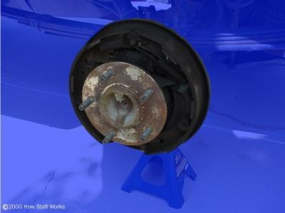
10 Drum brakes The drum spins with the wheel The flange is fixed with respect to the chassis 10


11 Drum brakes Brake shoe Drum (inside view) 11
12 Drum brake Braking factor is the mechanical advantage between the actuating force (input) and the braking force (output) It comes 12
13 Drum brake The leading shoe A. The friction force creates a moment that applies the shoe against the drum and the lining pad and thus increases the friction force The system is self actuated so it yields a high mechanical advantage This may lead to a brake locking The trailing shoe B The friction force tends to create of repulsive moment thus reducing the contact force The mechanical advantage is lower It requires a higher actuation force It is not subject to self locking Smart combination of trailing and leading shoes and their lining materials may lead to on demand braking factors 13

14 Drum brakes The conventional design consists in an internal brake shoe that is applied on the inner surface of the drum. The usual drum brake includes two shoes in one drum. According to the type of the clamping force and of the shoe support, the drum brakes are classified in different categories: Simplex-brake Duplex-brake Servo brake Duo-duplex-brake Duo-servo-brake 14

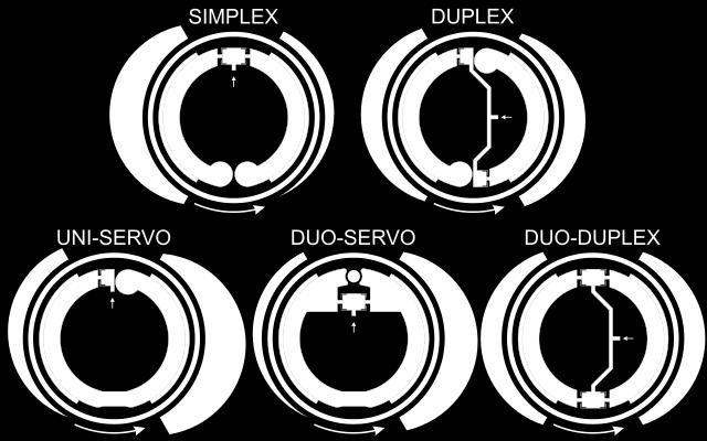
15 Drum brakes 15


16 Drum brakes Drum brake simplex -Double brake cylinder -Axle fixed rotation point -One leading shoe and one trailing shoe -Independent of rotation direction Drum brake duplex - braking with two leading brake shoes or, when backing-up, with two trailing brake shoes 16

 -Operation of the service brake via the pistons in the wheel cylinder 17 -Operation of the parking brake via a")
17 Drum brakes Drum brake servo - Actuation by a single double brake cylinder - Supporting force of the primary shoe is the application force of the secondary shoe - Transmission of the frictional forces of one brake shoe to the other Drum brake with parking brake - Operation of the brake shoes via the wheel brake cylinder -Function of the leading and trailing shoes (the leading shoe is pulled onto the drum, the trailing shoe is pushed away) -Operation of the service brake via the pistons in the wheel cylinder 17 -Operation of the parking brake via a linkage

18 Drum brakes 18

19 Drum brakes 19


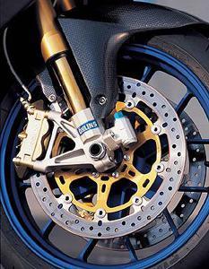
20 Disk brakes Car Motorbike 20

21 Disk brakes: definitions 21

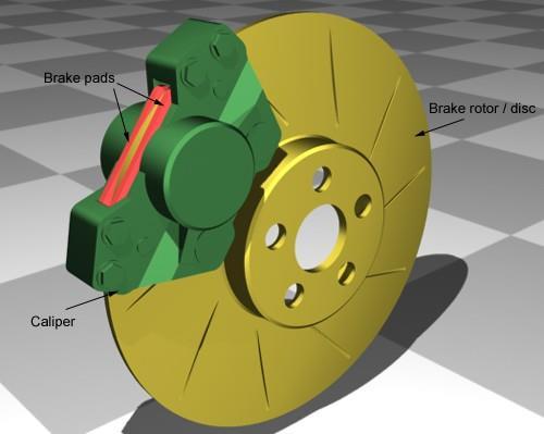
22 Disk brakes The disk brakes include A disk that is connected to the wheel and so it is spinning A calliper that supports one or several pistons on which are mounted the friction pad. The calliper is fixed with respect to the chassis There can be one or several pistons Friction pads made of high friction materials One can distinguish between The fixed calliper The floating calliper or self-adjusting brakes 22


23 Disk brakes Ventilated disk brakes Disk brakes 23


24 Self adjusting/floating and fixed callipers Floating calliper disk brake Fixed calliper disk brake 24


25 Self adjusting and fixed callipers Floating calliper disk brake Fixed calliper disk brake 25

26 Self adjusting callipers Operating principle of floating calliper 26

27 Floating calliper with adjustment Adjustment mechanism for a floating calliper 27
28 Brake pads The pads must resist to high temperature (about 600 C to 700 C) and to important efforts The pads are made of high friction materials with friction coefficient in between 0,25 and 0,5 The pads must: Preserve their high friction coefficient independently of the speed, of the contact pressure, and of the temperature. Resist to the wear without attacking the disk Do not produce stick-slip behaviour and noise Recover their friction properties after being wet The reduction of the efficiency of pad materials with the temperature is known as the fading. It can conduct to the loss of braking. 28

29 Disk braking factor The braking factor of a disk brake 29
30 Drum brakes v.s. disk brakes DRUM BRAKES High braking factor and so low braking actuation effort Drawback of the high braking factor: sensitivity of the friction coefficient of pads can lead to chattering and vibrations Braking torque variation with time Difficulty to maintain a good braking balance Stopping distance can be longer DISK BRAKES Lower braking factor and so higher braking effort More constant brake torque Braking torque rather constant Better braking distribution Stopping distance is lower 30
31 Drum brakes v.s. disk brakes T b = f ( P, speed, temperature) a Gillespie: Fig. 3.3 : Measurement of brake torque for drum brakes and disk brakes on a braking dynamometer 31
32 BRAKING SYSTEM 32
33 Command and actuation of the braking system In a braking system, one must distinguish: The braking device itself that is the drum and disk brakes The command and actuation system that encompasses all the actuation components of the brakes and their command devices Specifications of the braking system: Short response time Smooth and precise control force by the driver Requires a moderate actuation effort from the driver Braking distribution between the two wheels of a same axle, whatever could be the orientation and the motion of the wheels Distribution of the braking forces between front and rear axles as a function of the vertical loads To be able to stop the vehicle even in case of mal function of the braking circuit 33
34 Command and actuation of the braking system Types of a actuation for a braking system: Mechanical actuation using rigid rods or soft cables (Bowden cables) Hydraulic actuation Pneumatic actuation (mostly used on industrial vehicles) For all vehicles, the ECE regulation prescribes to have two different braking actuation systems on board. The must work independently. For passenger cars, we have generally: A mechanical actuation system for the emergency brake and the parking brake called hand brake A hydraulic braking system for the main braking system 34
35 Command and actuation of the braking system Emergency and parking brakes of the Ford Focus
36 Command and actuation of the braking system Object of the emergency and parking brake In case of malfunction, it must be able to stop the vehicle within good conditions (to be defined) When stopped, the system must be able to maintain the permanent rest conditions The parking system acts only on a single axle The emergency and parking braking system can (not mandatory): Be integrated to the drum brakes Be integrated in the calipers Include some independent calipers with their proper set of pads Be present as a small drum brake system integrated in the disk bowl 36


37 Command and actuation of the braking system Mémeteau Fig. 9.3 Parking brake integrated in a disk brake Mémeteau Fig. 9.4 Drum parking brake in a disk brake 37
38 Parking brake systems Generally the mechanical actuation is sufficient for emergency and parking brakes: The system is independent of the main brake system (hydraulic or pneumatic) Keep a constant effectiveness even for long parking periods The drawbacks of the mechanical actuation systems are: Bad distribution of the braking force on the axles or even between different axles Bad braking stability during suspension jounce/bounce, wheel steering because the system is based on straight lines mechanical components (cables, rods) Low efficiency because of the various internal frictions Risks of seizure Wear and elongation of the cables Progressive failure of the cables by progressive failure of the filaments 38
39 Hydraulic actuation system An hydraulic command system includes: A reservoir of hydraulic liquid A power source or the master cylinder that transforms the brake pedal pressure in hydraulic energy Receivers: that convert the hydraulic energy into actuating force of the shoes or of friction pads. Un network of hydraulic pipes connecting the source to the receivers. 39

40 Basic hydraulic system Mémeteau Fig. 9.3 Basic hydraulic command system 40
41 Hydraulic actuation system Advantages of hydraulic systems: Perfect repartition of the braking force to the wheels of an axle (the pressure is equal everywhere because of Pascal s principle) Possible amplification of the force when using with different piston sections in the master cylinder and in the brake pistons The pipes can bend and adapt easily the tortuous links The frictions are very weak The force amplification mechanism in the braking system results from: Mechanical amplification, by a system of levers Hydraulic amplification by using different section ratio 41

42 Force amplification mechanisms Lever systems Hydraulic system with different pistons surfaces 42

43 Master cylinder 43

44 Master cylinder Mèmeteau Fig
45 Master cylinder Components of the master cylinder: A cylindrical body communicating with the reservoir by an opening in which there is fit slotted elastic pin At the front end, one or several holes communicating with the pipes to the receiving brake cylinders A valve for the residual pressure for the drum disks hydraulic circuits A piston sliding in the cylinder bore A second ring that insure the sealing with respect to outer A spring for the recall of the piston that keeps the pressure valve and the primary cups 45
46 Double braking circuits Requirement for a double braking circuit: If the four receiving pistons are connected to a single network of pipes and to the master cylinder, In case of leakage, the pressure drops everywhere in the pipe network coming to a total failure of the braking system With a double braking circuit, one increases the safety and the reliability of the system because some braking capability is preserved. Double braking circuit: A tandem master cylinder Two reservoirs Two pistons (primary and secondary ones) Two independent networks of pipes 46
47 Double braking circuits One circuit for two wheels: Parallel or cross lay-out Front circuit is doubled: Parallel or triangular lay out Completely doubled circuit 47

48 Tandem master cylinder 48
49 Tandem master cylinder Normal operation of a tandem master cylinder When the brake pedal is depressed, the rod is pushed and then is pushes the primary piston The pressure growths in the primary cylinder and the fluid is pushed in the primary circuit. The pressure in the first cylinder acts on the wall of the second piston, and the pressure growths as well in the secondary cylinder and the fluid is also sent into the secondary circuit. In case of normal operation, the pressure is the same in the two circuits. In case of leakage, the system continues working but with a longer displacement of the brake pedal 49

50 Tandem master cylinder Working principle of a tandem master cylinder 50
51 Tandem master cylinder In case of a leakage, the tandem master cylinder works as following: Let a leakage in circuit 1. The pressure drops between 1 and 2. The piston 1 is pushed without any resistance until coming into contact with the face of the piston 2. When the two pistons are in contact, the system works as a single piston The circuit 2 continues working but the driver feels a longer displacement of the brake pedal to be actuated. This gives a warning feedback signal to the driver. 51

52 Hydraulic circuit in case of a leakage 52

53 Combination valve The combination valve has three separate functions: Pressure metering valve Pressure differential switch Proportioning valve 53
54 Pressure metering valve The pressure metering valve is required for vehicles with both disk brakes in front and drum brakes on the rear axles. The brake pads of brake disks are remaining nearly in contact with the disks whereas the shoes in drum brakes are extracted from the drum by a spring elements. Thus the time responses of drum brakes is longer than disk brakes. For braking stability, one has to delay the actuation of the disk brakes on front wheels. The metering valve is a calibrated valve that allows only a actuation of the front brake disks over a given threshold of pressure 54

55 Pressure differential switch The pressure differential switch is a device devoted to warn the driver when there is a pressure drop in one of the circuits It is made of a small piston whose faces are in contact with the pressure in the two circuits. A pressure difference conducts to a displacement of the piston which insures a electrical contact to switch on a light for the driver 55
56 Proportioning valve and pressure limitation The proportioning valve is a valve that reduces the pressure in the rear brake pistons to prevent the rear wheel locking. Front Rear 56
57 Braking assistance 57
58 Braking assistance Braking assistance = device that enables to develop a high pressure in the hydraulic braking circuit with a low or moderate pedal force. Devices enabling the braking efforts: Mechanical systems: lever arms Hydraulic systems: different cross sections of the pistons Brake assist systems: Magnification of the effort developed without using mechanisms that requires a increase in the pedal displacement. 58
59 Braking assistance Mèmeteau Fig
60 Braking assistance Source of braking assistance: Create a low pressure using the pressure loss in the admission manifold (for SI engines) and a vacuum pump (for CI engines) Create a high pressure in the hydraulic fluid developed by a hydraulic pump Create a high pressure of air developed by a compressor (as in industrial and heavy utility vehicles) Assistance is obtained by the action of the difference of pressure across the two faces of a membrane The modulus of the actuating force is the sum of The braking force on the pedal multiplied by the mechanical advantage of the pedal The additional force of the assistance device 60

61 Braking assistance Mèmeteau Fig

62 Braking assistance Mèmeteau Fig


63 Braking assistance System of braking assistance Hydrovac Master vac 63

64 Vacuum assist unit The vacuum assist unit is inserted between the brake pedal and the master cylinder. 64

65 Vacuum assist unit It includes: A cylinder a large diameter (in green) The two chambers are separated by a sliding piston The piston pushes the actuation rod of the master cylinder 65
66 Master Vac working principle The device uses the low pressure available from engine admission pipes When the strut is pressed, the air at atmospheric pressure can come into contact with the diaphragm in the right hand side part The pressure difference between the two sides of the diagram pushes the strut of the master cylinder As the pressure difference is rather limited, the diameter of the piston must be large to create a significant force 66
67 Master Vac working principle When the pressure on the braking pedal is relaxed, the atmospheric pressure valve is released The right hand side of the diaphragm is set under depression The assistance force is cancelled by returning to initial position 67

68 The check-valve The check-valve is a one-way valve that allows the low pressure air to leave the master vac low pressure chamber but not to enter into the master vac So in case of pressure leakage or engine stop, or in case of a pressure leakage not to admit atmospheric air into the chamber This allows to guarantee that the master is able to work several times and operate safely an assistance force whereas the engine has stopped working 68
69 Summary 69

70 Summary: the braking system 70
MECA0494 : Braking systems
 MECA0494 : Braking systems Pierre Duysinx Research Center in Sustainable Automotive Technologies of University of Liege Academic Year 2017-2018 1 MECA0494 Driveline and Braking Systems Monday 23/10 (@ULG)
Vehicle Performance. Pierre Duysinx. Research Center in Sustainable Automotive Technologies of University of Liege Academic Year
 Vehicle Performance Pierre Duysinx Research Center in Sustainable Automotive Technologies of University of Liege Academic Year 2018-2019 1 Lesson 3: Tractive forces 2 Outline POWER AND TRACTIVE FORCE AT
DESCRIPTION & OPERATION
 DESCRIPTION & OPERATION BRAKE BOOSTER Delco-Moraine Single Diaphragm A combined vacuum-hydraulic unit which uses a combination of intake manifold vacuum and atmospheric pressure to provide power assist.
Chapter 33 Fundamentals of Hydraulic and Air-Over-Hydraulic Braking Systems
 Chapter 33 Fundamentals of Hydraulic and Air-Over-Hydraulic Braking Systems Introduction Vehicle s braking system must meet the following requirements: To adequately and safely reduce a vehicle s speed,
Brake System Operation
 Brake System Brake System Operation Donald Jones Brookhaven College Master cylinder Brake lines Hydraulic valves Disc brakes Drum brakes Power assist unit Parking brake Antilock system Brake System Functions
DESIGN, ANALYSIS AND FABRICATION OF BRAKING SYSTEM WITH REAR INBOARD BRAKES IN BAJA ATV
 DESIGN, ANALYSIS AND FABRICATION OF BRAKING SYSTEM WITH REAR INBOARD BRAKES IN BAJA ATV Aman Sharma 1, Prakhar Amrute 2, Suryakant Singh Thakur 3, Jatin Shrivastav 4 1,2,3,4Department of Mechanical Engineering,
SECTION 4A BRAKE SYSTEM TABLE OF CONTENTS
 SECTION 4A BRAKE SYSTEM TABLE OF CONTENTS Description and Operation... 4A-2 Braking System Testing... 4A-2 Hydraulic Brake System... 4A-2 Brake Pedal... 4A-2 Master Cylinder... 4A-2 Brake Booster... 4A-3
FUNDAMENTAL PRINCIPLES
 Section 1 FUNDAMENTAL PRINCIPLES Lesson Objectives 1. Describe the cycle of heat as it applies to automotive brakes. 2. Explain the effect of heat transfer as it relates to brake fade. 3. Describe how
BRAKES. Section III REAR AXLE DATA AND SPECIFICATIONS HAND BRAKE CHRYSLER SERVICE MANUAL BRAKES 17
 BRAKES 17 There is no basic design change in the rear axle and sure grip differential except the larger diameter pinion shaft is now used on all models for 1959. The Service Procedures will remain the
BRAKE SYSTEM FUNDAMENTALS KARAN BHARDIYA ASSISTANT MANAGER -R&D ENDURANCE TECHNOLOGIES PVT.LTD. DISC BRAKES
 BRAKE SYSTEM FUNDAMENTALS KARAN BHARDIYA ASSISTANT MANAGER -R&D ENDURANCE TECHNOLOGIES PVT.LTD. DISC BRAKES AUTOMOTIVE BRAKING SYSTEMS How brakes manufacturing industry is different then rest of the automotive
Modern Auto Tech Study Guide Chapters 71 & 73 Pages Brake Systems 49 Points. Automotive Service
 Modern Auto Tech Study Guide Chapters 71 & 73 Pages 1369 1444 Brake Systems 49 Points 1. Automotive systems use to stop, slow or to hold the wheels from turning. Brake, Friction Brake, Fraction Brake,
Braking System Layout
 The Braking System The energy used to accelerate or move a vehicle from rest to a certain speed is called Kinetic i (moving) energy. To slow the vehicle down, this kinetic energy must be converted or changed,
MASTER CYLINDER. Section 2. Lesson Objectives
 MASTER CYLINDER Lesson Objectives 1. Explain the difference between conventional and diagonal split piping system and their application. 2. Describe the function of the compensating port of the master
C. Brake pads Replaceable friction surfaces that are forced against the rotor by the caliper piston.
 BRAKES UNIT 1: INTRODUCTION TO BRAKE SYSTEMS LESSON 1: FUNDAMENTAL PRINCIPLES OF BRAKE SYSTEMS I. Terms and definitions A. Brake fading Loss of brakes, usually due to heat. B. Brake lining Material mounted
Vehicle dynamics Suspension effects on cornering
 Vehicle dynamics Suspension effects on cornering Pierre Duysinx LTAS Automotive Engineering University of Liege Academic Year 2013-2014 1 Bibliography T. Gillespie. «Fundamentals of vehicle Dynamics»,
MECA0063 : Driveline systems
 MECA0063 : Driveline systems Pierre Duysinx Research Center in Sustainable Automotive Technologies of University of Liege Academic Year 2018-2019 1 Bibliography T. Gillespie. «Fundamentals of vehicle Dynamics»,
Brake Systems. Introduction
 Brake Systems Figure 1. A Typical Brake System Introduction The brake system (Figure 1) is designed to slow and halt the motion of a vehicle. To do that, various components within a hydraulic brake system
Introduction and Overview to Friction Brakes. Course 105 PREVIEW ONLY PARTICIPANT GUIDE
 Introduction and Overview to Friction Brakes Course 105 PARTICIPANT GUIDE Table of Contents How to Use the Participant Guide... ii MODULE 1...1 General Principles and Terminology...1 1-1 Safety Review...2
FUNDAMENTAL PRINCIPLES
 FUNDAMENTAL PRINCIPLES Fundamental Principles The most important safety feature of an automobile is its brake system. The ability of a braking system to provide safe, repeatable stopping is the key to
MECA0492 : Introduction to Vehicle Stability Control
 MECA0492 : Introduction to Vehicle Staility Control Pierre Duysinx Research Center in Sustainale Automotive Technologies of University of Liege Academic Year 2017-2018 1 Biliography T. Gillespie. «Fundamentals
BRAKE SYSTEM DESIGN AND THEORY
 RAKE SYSTEM DESIGN AND THEORY Aircraft brake systems perform multiple functions. They must be able to hold the aircraft back at full static engine run-up, provide adequate control during ground taxi operations,
AUTOMOTIVE ENGINEERING
 AUTOMOTIVE ENGINEERING UNIT 4 BRAKES & SUSPENSION TYPES OF BRAKES The two main types of friction brake are drum brake and disc brake. In both types a fixed (non-rotating) shoe or pad rubs against a moving
MECA0492 : Vehicle dynamics
 MECA0492 : Vehicle dynamics Pierre Duysinx Research Center in Sustainable Automotive Technologies of University of Liege Academic Year 2017-2018 1 Bibliography T. Gillespie. «Fundamentals of vehicle Dynamics»,
White Paper: The Physics of Braking Systems
 White Paper: The Physics of Braking Systems The Conservation of Energy The braking system exists to convert the energy of a vehicle in motion into thermal energy, more commonly referred to as heat. From
Vehicle Performance. Pierre Duysinx. Research Center in Sustainable Automotive Technologies of University of Liege Academic Year
 Vehicle Performance Pierre Duysinx Research Center in Sustainable Automotive Technologies of University of Liege Academic Year 2018-2019 1 Lesson 1: Power sources 2 Outline MOTORIZATION CHARACTERISTICS
Module 11: Antilock Brakes Systems
 ÂÂ ABS Brake System Antilock Brake System Operation Principles of ABS Braking ABS Master Cylinder Hydraulic Control Unit Wheel Speed Sensors ABS Electronic Control Unit Terms and Definitions Purposes for
To study about various types of braking system.
 To study about various types of braking system INTRODUCTION The system is purely mechanical means & is independent of the hydraulic system which controls the brake normally. A brake commonly referred to
Unit HV04K Knowledge of Heavy Vehicle Chassis Units and Components
 Assessment Requirements Unit HV04K Knowledge of Heavy Vehicle Chassis Units and Components Content: Chassis layouts i. types of chassis ii. axle configurations iii. rear steered axles iv. self-steered
SERVICE BRAKES GROUP 35A 35A-1 CONTENTS GENERAL DESCRIPTION... 35A-2 FRONT DISC BRAKE... 35A-5 MASTER CYLINDER... 35A-4 REAR DISC BRAKE...
 35A-1 GROUP 35A CONTENTS GENERAL DESCRIPTION......... 35A-2 MASTER CYLINDER............. 35A-4 FRONT DISC BRAKE............. 35A-5 REAR DISC BRAKE.............. 35A-6 BRAKE BOOSTER ASSEMBLY.... 35A-4 35A-2
BRAKE BOOSTER. Section 5. Brake Booster. Construction. Single Diaphragm Booster
 BRAKE BOOSTER Brake Booster The brake booster is designed to create a greater braking force from a minimum pedal effort, using a difference in atmospheric pressure and the engine s manifold vacuum. It
INSTALLATION INSTRUCTIONS
 INSTALLATION INSTRUCTIONS REAR DISC CONVERSION KIT A126-2 1988-98 C1500 2WD 10" REAR DRUM Thank you for choosing STAINLESS STEEL BRAKES CORPORATION for your braking needs. Pleases take the time to read
DEVELOPMENT OF HYDRAULIC BRAKE DESIGN SYSTEM APPLICATION
 DEVELOPMENT OF HYDRAULIC BRAKE DESIGN SYSTEM APPLICATION AMOGH DESHPANDE Department of Mechanical Engineering, VJTI, Matunga, Mumbai, India ABSTRACT The brakes which are actuated by the hydraulic pressure
Brake System Fundamentals Chapter 71 Name Date Period
 Brake System Fundamentals Chapter 71 Name Date Period Basic Brake System Matching 1. Metal tubing and rubber hose that transmit pressure to the wheel brake assemblies. 2. Mechanical system for applying
Auto Tech 2 SEMESTER Exam Study Sheet
 Auto Tech 2 SEMESTER Exam Study Sheet 1. Safety 2. Are all brakes are self adjusting? 3. The front brakes do What % of the stopping. 4. The part of the disc brakes that turns or rotates with the wheel
UNIT I CLASSIFICATION AND REQUIREMENTS OF OFF ROAD VEHICLES
 UNIT I CLASSIFICATION AND REQUIREMENTS OF OFF ROAD VEHICLES INTRODUCTION It is a common fact that we find a wide variety of construction machines on every construction sites, which make the construction
This file is available for free download at
 This file is available for free download at http://www.iluvmyrx7.com This file is fully text-searchable select Edit and Find and type in what you re looking for. This file is intended more for online viewing
Module 6: Air Foundation Brakes
 Air Brakes Terms and Definitions Basic Components That Make Up Air Foundation Brakes Types of Air Foundation Brakes Parts of a Cam Foundation Brake Parts of a Wedge Foundation Brake Parts of a Disc Foundation
COURSE LEARNING OUTCOMES
 COURSE LEARNING OUTCOMES No. Course Learning Outcome 1. 2. Compare working principle and identify advantages/disadvantages between the disc and drum brake systems used in passenger vehicles Analyze deceleration
GM Full-Size Trucks Repair Information
 . 1 of 12 12/26/2009 10:47 AM GM Full-Size Trucks 1988-1998 Repair Information Brake Shoes INSPECTION REMOVAL & INSTALLATION ADJUSTMENT INSPECTION 1. 2. 3. 4. 5. Raise and support the rear end on jackstands.
TRADE OF HEAVY VEHICLE MECHANIC
 TRADE OF HEAVY VEHICLE MECHANIC PHASE 2 Module 5 Braking Systems UNIT: 1 Table of Contents 1. Learning Outcome... 1 1.1 Key Learning Points... 1 2.0 Health and Safety... 3 2.1 Principles of Braking...
ANTI-LOCK BRAKES. Section 9. Fundamental ABS Systems. ABS System Diagram
 ANTI-LOCK BRAKES Fundamental ABS Systems Toyota Antilock Brake Systems (ABS) are integrated with the conventional braking system. They use a computer controlled actuator unit, between the brake master
SECTION 4A HYDRAULIC BRAKES
 SECTION 4A HYDRAULIC BRAKES Caution: Disconnect the negative battery cable before removing or installing any electrical unit or when a tool or equipment could easily come in contact with exposed electrical
MECA0494 : Driveline systems
 MECA0494 : Driveline systems Pierre Duysinx Research Center in Sustainable Automotive Technologies of University of Liege Academic Year 2017-2018 1 MECA0494 Driveline and Braking Systems Tuesday 16/10
ASE Practice Test A5 Brakes
 ASE Practice Test A5 Brakes Hydraulic System Diagnosis and Repair 1) A spongy brake pedal may be caused by: a. ABS Diagnostic Trouble Code set b. Frozen caliper piston c. Defective metering valve d. Air
LECTURE-23: Basic concept of Hydro-Static Transmission (HST) Systems
 Systems") MODULE-6 : HYDROSTATIC TRANSMISSION SYSTEMS LECTURE-23: Basic concept of Hydro-Static Transmission (HST) Systems 1. INTRODUCTION The need for large power transmissions in tight space and their control
MODULE-6 : HYDROSTATIC TRANSMISSION SYSTEMS LECTURE-23: Basic concept of Hydro-Static Transmission (HST) Systems 1. INTRODUCTION The need for large power transmissions in tight space and their control
BRAKE SYSTEM Return To Main Table of Contents
 BRAKE SYSTEM Return To Main Table of Contents GENERAL... 2 BRAKE PEDAL... 10 MASTER CYLINDER... 13 BRAKE BOOSTER... 16 BRAKE LINE... 18 PROPORTIONING VALVE... 19 FRONT DISC BRAKE... 20 REAR DRUM BRAKE...
Inspection and Basic Maintenance of Brake Systems
 Inspection and Basic Maintenance of Brake Systems 11-1 Types Air brakes Hydraulic brakes Secondary braking systems 11-2 Air Brake System Most large, modern fire apparatus are equipped with air-operated
AN EXPLANATION OF CIRCUITS CARTER YH HORIZONTAL CLIMATIC CONTROL CARBURETER
 AN EXPLANATION OF CIRCUITS CARTER YH HORIZONTAL CLIMATIC CONTROL CARBURETER The Carter Model YH carbureter may be compared with a Carter YF downdraft carbureter with the circuits rearranged to operate
Design and Fabrication of Sequencing Circuit with Single Double Acting Cylinder
 Design and Fabrication of Sequencing Circuit with Single Double Acting Cylinder V.G.Vijaya Department of Mechatronics Engineering, Bharath University, Chennai 600073, India ABSTRACT: This project deals
Parking brake Mechanical brake acting on rear wheels
 11 Brake System 11.1 General SPECIFICATIONS EJTC0010 Master cylinder Type Tandem type I.D. mm(in.) 20.64 mm (0.813 in.) Fluid level warning sensor Provided Brake booster Type Vacuum Boosting ratio 4.0
1. INTRODUCTION. Anti-lock Braking System
 1. INTRODUCTION Car manufacturers world wide are vying with each other to invent more reliable gadgets there by coming closer to the dream of the Advanced safety vehicle or Ultimate safety vehicle, on
Overview. KNOTT brakes overview The basics for around 2000 solutions BRAKES. We make your brake
 Overview BRAKES KNOTT brakes overview The basics for around 2000 solutions www.knott.de We make your brake KNOTT develops and produces individual brake solutions for all branches: from agriculture and
Your Brakes. Fundamentals of Braking
 B U S S E R V I C E, I N C. Your Brakes Fundamentals of Braking There are a variety of mechanical forces and physical components that make up the braking system of your coach. The forces that effect your
A proportioning valve is used to regulate brake pressure between front and rear brakes. Rear brakes on all models are self-adjusting.
 Page 1 of 21 ARTICLE BEGINNING DESCRIPTION & OPERATION WARNING: For warnings and procedures regarding vehicles equipped with Anti- Lock Brake Systems (ABS), see ANTI-LOCK BRAKE SYSTEM article in the BRAKES
Design and Validation of Hydraulic brake system for Utility Vehicle
 ISSN 2395-1621 Design and Validation of Hydraulic brake system for Utility Vehicle #1 K.M.Pavan, #2 Dr. A.G.Thakur 1 pavan56@yahoo.com 2 ajay_raja34@yahoo.com #12 Department of Mechanical Engineering,
REMOVAL & INSTALLATION
 REMOVAL & INSTALLATION REAR BRAKE CALIPER NOTE: For rear disc pad removal and installation, DO NOT disconnect brake hose from caliper (wire aside). Replace all pads on an axle if wear indicator on any
Hydraulic Brakes and Air-Over-Hydraulic Brake Systems
 Hydraulic Brakes and Air-Over-Hydraulic Brake Systems Objectives Describe the principles of operation of a hydraulic brake system. Identify the major components in a truck hydraulic brake system. Describe
1. SYSTEM OVERVIEW. 1) Terms and Definition. 2) Functions
 Terms and Definition. 2) Functions") 485000 093 1. SYSTEM OVERVIEW 1) Terms and Definition CBS: Conventional Brake System ABS: AntiLock Brake System EBD: Electronic brakeforce Distribution ESP: Electronic Stability Program ABD: Automatic
485000 093 1. SYSTEM OVERVIEW 1) Terms and Definition CBS: Conventional Brake System ABS: AntiLock Brake System EBD: Electronic brakeforce Distribution ESP: Electronic Stability Program ABD: Automatic
Performance concept: Chassis
 Chassis Performance concept: Chassis Total vehicle concept Chassis mechanics Mechatronic chassis systems Systematic attention to driving dynamic requirements in total vehicle concept Driver-oriented operating
An Introduction to Brake Systems
 An Introduction to Brake Systems SAE Brake Colloquium October 6th 2002 DaimlerChrysler This presentation was originally created as a one hour lecture class. This is not intended to be a stand alone text
COASTAL BEND COLLEGE AUTOMOTIVE TECHNOLOGY SYLLABUS (rev. Fall 2012)
") COASTAL BEND COLLEGE AUTOMOTIVE TECHNOLOGY SYLLABUS (rev. Fall 2012) AUMT 1310: Automotive Brake Systems SEMESTER HOURS: 3 TEXTBOOK Automotive Technology A systems Approach COURSE DESCRIPTION; Operation
COASTAL BEND COLLEGE AUTOMOTIVE TECHNOLOGY SYLLABUS (rev. Fall 2012) AUMT 1310: Automotive Brake Systems SEMESTER HOURS: 3 TEXTBOOK Automotive Technology A systems Approach COURSE DESCRIPTION; Operation
2006 Mercedes-Benz USA, LLC. Chassis and Drivetrain 42
 Page 1 of 5 Chassis and Drivetrain 42 Brakes Anti-lock Brake System (ABS) 4-Wheel Electronic Traction Control System (4-ETS) Electronic Brake Proportioning (EBP) System Description The hydraulic pressure
INSTALLATION INSTRUCTIONS
 INSTALLATION INSTRUCTIONS REAR DISC BRAKE CONVERSION KIT A125-3 1965-72 GM A-BODY 10 & 12 BOLT AXLES Thank you for choosing STAINLESS STEEL BRAKES CORPORATION for your braking needs. Pleases take the time
Design and Integration of Suspension, Brake and Steering Systems for a Formula SAE Race Car
 Design and Integration of Suspension, Brake and Steering Systems for a Formula SAE Race Car Mark Holveck 01, Rodolphe Poussot 00, Harris Yong 00 Final Report May 5, 2000 MAE 340/440 Advisor: Prof. S. Bogdonoff
Hydro-Max Hydraulic Brake Booster and Master Cylinder. Technical Manual
 Hydro-Max Hydraulic Brake Booster and Master Cylinder Technical Manual * 5+0 Important Service Notes The information in this publication was current at the time of printing. The information presented in
Class 5 to 7 Truck and Bus Hydraulic Brake System
 Class 5 to 7 Truck and Bus Hydraulic Brake System Diagnostic Guide 2nd Edition www.bosch.us Important Service tes The information in this publication was current at the time of printing. The information
BRAKE SYSTEM Article Text 1996 Toyota RAV4 For Copyright 1998 Mitchell Repair Information Company, LLC Wednesday, September 13, :30PM
 Article Text ARTICLE BEGINNING 1996 BRAKES Toyota - Disc & Drum RAV4 * PLEASE READ THIS FIRST * WARNING: For warnings and procedures regarding vehicles equipped with Anti-Lock Brake Systems (ABS), see
three different ways, so it is important to be aware of how flow is to be specified
 Flow-control valves Flow-control valves include simple s to sophisticated closed-loop electrohydraulic valves that automatically adjust to variations in pressure and temperature. The purpose of flow control
Installation Instructions
 Installation Instructions Rear Disc Brake Conversion Kit Item # RC4001, RC4001X Applications: Mopar 7.25, 8.25, 9.25 Axles Thank you for choosing Leed Brakes for your automotive product needs. Before you
INSTALLATION INSTRUCTIONS
 INSTALLATION INSTRUCTIONS REAR DISC BRAKE CONVERSION KIT A126-1 1973-87 CHEVROLET 1/2 TON 2WD Thank you for choosing STAINLESS STEEL BRAKES CORPORATION for your braking needs. Pleases take the time to
6-speed manual gearbox 0A5
 Service Training Self-study programme 320 6-speed manual gearbox 0A5 Design and function S320_002 In addition to meeting increasing technical demands, modern cars also have to represent effective space
INSTALLATION INSTRUCTIONS
 INSTALLATION INSTRUCTIONS REAR DRUM TO DISC BRAKE CONVERSION KIT A118 pre-1985 Ford F150 (except 1983-1984 w/super H/D axle) Thank you for choosing STAINLESS STEEL BRAKES CORPORATION for your braking needs.
Original ATE master brake cylinders OEM quality since the 1920s
 Original ATE master brake cylinders OEM quality since the 1920s Expansion port TMC Central valve TMC Plunger TMC 1 Original ATE master brake cylinders Since the mid-1920s Continental has been supplying
INSTALLATION INSTRUCTIONS
 INSTALLATION INSTRUCTIONS REAR DISC BRAKE CONVERSION KIT A125-2 1955-70 FULL SIZE CHEVROLET Thank you for choosing STAINLESS STEEL BRAKES CORPORATION for your braking needs. Pleases take the time to read
INSTALLATION INSTRUCTIONS PERFORMANCE AT THE WHEELS KIT W125
 INSTALLATION INSTRUCTIONS PERFORMANCE AT THE WHEELS KIT W125 1968-81 CAMARO & FIREBIRD 10 & 12 BOLT W/"C" CLIPS Thank you for choosing STAINLESS STEEL BRAKES CORPORATION for your braking needs. Pleases
INSTALLATION INSTRUCTIONS
 INSTALLATION INSTRUCTIONS REAR CONVERSION KIT A111-2 (FORD 8" & 9" SMALL BEARING) & REAR CONVERSION KIT A111-3 (FORD 9 TORINO) Thank you for choosing STAINLESS STEEL BRAKES CORPORATION for your braking
SECTION 4A HYDRAULIC BRAKES
 SECTION 4A HYDRAULIC BRAKES CAUTION: Disconnect the negative battery cable before removing or installing any electrical unit or when a tool or equipment could easily come in contact with exposed electrical
CAUTION. Hydraulic Brakes. Braking Systems - Hydraulic
 Hydraulic Brakes The hydraulic brakes on your trailer are much like those on your automobile or light truck. The hydraulic fluid from a master cylinder or actuation system is used to actuate the wheel
ABS, 4-ETS and EBP BRAKES ANTI-LOCK BRAKE SYSTEM (ABS) 4-WHEEL ELECTRONIC TRACTION CONTROL SYSTEM (4-ETS) ELECTRONIC BRAKE PROPORTIONING (EBP)
 4-WHEEL ELECTRONIC TRACTION CONTROL SYSTEM (4-ETS) ELECTRONIC BRAKE PROPORTIONING (EBP)") 1 of 9 4/27/2008 7:52 AM Home Account Contact ALLDATA Log Out Help Select Vehicle New TSBs Technician's Reference Component Search: METRO TOYOTA OK 2002 Mercedes Benz Truck ML 320 (163.154) V6-3.2L (112.942)
1 of 9 4/27/2008 7:52 AM Home Account Contact ALLDATA Log Out Help Select Vehicle New TSBs Technician's Reference Component Search: METRO TOYOTA OK 2002 Mercedes Benz Truck ML 320 (163.154) V6-3.2L (112.942)
BRAKE SYSTEM Nissan 240SX DESCRIPTION BRAKE BLEEDING * PLEASE READ FIRST * BLEEDING PROCEDURES ADJUSTMENTS BRAKE PEDAL HEIGHT SPECS TABLE
 BRAKE SYSTEM 1990 Nissan 240SX 1990 BRAKE SYSTEMS Nissan Disc & Drum Axxess, Maxima, Pathfinder, Pickup, Pulsar NX, Sentra, Stanza, 240SX, 300ZX DESCRIPTION All brake systems are hydraulically operated
2003 Infiniti G35. CAUTION: When brake caliper is removed, DO NOT depress brake pedal, or piston will pop out.
 FRONT & REAR DISC PADS CAUTION: When brake caliper is removed, DO NOT depress brake pedal, or piston will pop out. To determine which brake system vehicle is equipped with, see MODEL IDENTIFICATION. Removal
Bearing retention and clearances
 Bearing retention and clearances Bearing retention 9 Radial retention 9 Axial retention 91 Positioning of single bearing assemblies 91 Positioning of two bearing assemblies 92 Axial retention processes
INSTALLATION INSTRUCTIONS
 INSTALLATION INSTRUCTIONS REAR DISC BRAKE CONVERSION KIT A158 1994-97 Dodge Ram 1500 (2WD & 4WD) and REAR DISC BRAKE CONVERSION KIT A158-1 1998-01 Dodge Ram 1500 (2WD & 4WD) Thank you for choosing STAINLESS
Fundamentals of Steering Systems ME5670
 Fundamentals of Steering Systems ME5670 Class timing Monday: 14:30 Hrs 16:00 Hrs Thursday: 16:30 Hrs 17:30 Hrs Lecture 3 Thomas Gillespie, Fundamentals of Vehicle Dynamics, SAE, 1992. http://www.me.utexas.edu/~longoria/vsdc/clog.html
Installation Instructions
 Installation Instructions Rear Disc Brake Conversion Kit Item # RC2001, RC2001X Applications: Mopar 8-3/4 & 9-3/4 Rear Axles Thank you for choosing Leed Brakes for your automotive product needs. Before
DRIVE-CONTROL COMPONENTS
 3-1 DRIVE-CONTROL COMPONENTS CONTENTS FRONT SUSPENSION................... 2 Lower Arms............................... 5 Strut Assemblies........................... 6 REAR SUSPENSION.....................
CH.4 Basic Components of Hydraulic and Pneumatic System/16 M HAP/17522/AE5G
 Content : 4.1 Hydraulic and Pneumatic actuators. 10 Marks Hydraulic Actuators - Hydraulic cylinders (single, double acting and telescopic) construction and working, Hydraulic motors (gear and piston type)
INSTALLATION INSTRUCTIONS R1 REAR CONVERSION KIT
 INSTALLATION INSTRUCTIONS R1 REAR CONVERSION KIT INSTRUCTION FOR ASSEMBLY OF JEEP CJ SERIES W/AMC 20 REAR AXLES, 5 x 5-1/2" BOLT CIRCLE WITH A130-4 FULL FLOATING AXLE OR A130-5 (1 PIECE AXLE) Thank you
CHASSIS CLUTCH CHASSIS. A dry type single plate clutch which is operated by hydraulic pressure is used.
 CHASSIS CLUTCH 47 CHASSIS CLUTCH DESCRIPTION A dry type single plate clutch which is operated by hydraulic pressure is used. 179CH01 Specifications Clutch Dry Single Plate Clutch, Diaphragm Spring Operation
Simulation of Brake Pressure Multiplier (BPM) through ANSYS 14.0 For Effective Braking in ATV
 through ANSYS 14.0 For Effective Braking in ATV") RESEARCH ARTICLE OPEN ACCESS Simulation of Brake Pressure Multiplier (BPM) through ANSYS 14.0 For Effective Braking in ATV Ronak Bandil 2, Anand Baghel 1,Akash Singh Parihar 2, Shubham Kumar Verma 2,Vikas
RESEARCH ARTICLE OPEN ACCESS Simulation of Brake Pressure Multiplier (BPM) through ANSYS 14.0 For Effective Braking in ATV Ronak Bandil 2, Anand Baghel 1,Akash Singh Parihar 2, Shubham Kumar Verma 2,Vikas
Mopar 8 3/4 & 9 3/4 (Dana) Installation Instructions Rear Disc Conversion
 Installation Instructions Rear Disc Conversion") Mopar 8 3/4 & 9 3/4 (Dana) Installation Instructions Rear Disc Conversion This kit is for either Mopar 8 ¾ or Mopar 9 ¾ (Dana). This kit is designed to work with axles with either GM 5 x 4.75 Bolt Pattern
Mopar 8 3/4 & 9 3/4 (Dana) Installation Instructions Rear Disc Conversion This kit is for either Mopar 8 ¾ or Mopar 9 ¾ (Dana). This kit is designed to work with axles with either GM 5 x 4.75 Bolt Pattern
1999 Toyota RAV BRAKES Disc & Drum - Trucks & Vans
 DESCRIPTION & OPERATION 1999-2000 BRAKES Disc & Drum - Trucks & Vans WARNING: For warnings and procedures regarding vehicles equipped with Anti-Lock Brake Systems (ABS), see appropriate ANTI-LOCK article.
INSTALLATION INSTRUCTIONS
 INSTALLATION INSTRUCTIONS PERFORMANCE AT THE WHEELS KITS W156-6 & W156-7 1965-74 MOPAR B & E BODY Thank you for choosing STAINLESS STEEL BRAKES CORPORATION for your braking needs. Pleases take the time
MECA0500: PLUG-IN HYBRID ELECTRIC VEHICLES. DESIGN AND CONTROL. Pierre Duysinx
 MECA0500: PLUG-IN HYBRID ELECTRIC VEHICLES. DESIGN AND CONTROL Pierre Duysinx Research Center in Sustainable Automotive Technologies of University of Liege Academic Year 2017-2018 1 References R. Bosch.
PARALLEL HYBRID ELECTRIC VEHICLES: DESIGN AND CONTROL. Pierre Duysinx. LTAS Automotive Engineering University of Liege Academic Year
 PARALLEL HYBRID ELECTRIC VEHICLES: DESIGN AND CONTROL Pierre Duysinx LTAS Automotive Engineering University of Liege Academic Year 2015-2016 1 References R. Bosch. «Automotive Handbook». 5th edition. 2002.
AUTOMOTIVE SPECIALIZATION (Brakes) STUDENT GRADE RECORD Career & Technical Education
 STUDENT GRADE RECORD Career & Technical Education") STUDENT GRADE RECORD Career & Technical Education Course Outline Modules Windham Module Test Module Competency Rating WINDHAM SCHOOL DISTRICT 1. CTE Orientation 2. Introduction to Brake Systems 3. Shop
STUDENT GRADE RECORD Career & Technical Education Course Outline Modules Windham Module Test Module Competency Rating WINDHAM SCHOOL DISTRICT 1. CTE Orientation 2. Introduction to Brake Systems 3. Shop
BURQUIP INTERNATIONAL (PTY) LTD
 LTD") Chapter 6 Transmission The transmission system comprises all of the components that transfer the force and movement from the Braked Coupler to the inertia brakes in the axles. Fit the axles to the trailers
Chapter 6 Transmission The transmission system comprises all of the components that transfer the force and movement from the Braked Coupler to the inertia brakes in the axles. Fit the axles to the trailers
Module Leader: Prof.Ashok Meti
 AEL2501 Modern Automotive Systems Common for: AEL, AE and APD courses Module Leader: Prof.Ashok Meti 1 Module Aims and Summary The aim of this module is to prepare the students to critically evaluate the
US ARMY LIGHT WHEEL VEHICLE MECHANIC MOS 63B SKILL LEVEL 3 COURSE WHEELED VEHICLE BRAKING SYSTEMS SUBCOURSE NO. OD1008
 US ARMY LIGHT WHEEL VEHICLE MECHANIC MOS 63B SKILL LEVEL 3 COURSE WHEELED VEHICLE BRAKING SYSTEMS SUBCOURSE NO. OD1008 US Army Ordnance Center and School Five Credit Hours GENERAL The Wheeled Vehicle Braking
ASSEMBLY INSTRUCTIONS
 ASSEMBLY INSTRUCTIONS FOR DYNALITE PRO SERIES FRONT HUB KIT WITH.75 DIAMETER VENTED ROTOR 970-973 FORD MUSTANG (DRUM / DISC SPINDLE) PART NUMBER GROUP 0-905 WARNING INSTALLATION OF THIS KIT SHOULD ONLY