British Aerospace Hawk Mk. 51
|
|
|
- Timothy Glenn
- 6 years ago
- Views:
Transcription

1 British Aerospace Hawk Mk mm class Electric Ducted Fan Sport Jet Designed By Al Sprosta Construction Guide Page 1 of 47
2 Thank You and Introduction: Thank you for your purchase of the Mr. Boogie designed British Aerospace Hawk Sport Jet. This model of the Hawk was born out of a desire to have a large size BAe Hawk that was reasonably scale, and fit comfortably in the 70mm electric ducted fan class. Sophisticated CAD tools were employed in the development of this model. This allowed for the optimization of model sized flight characteristics, as well as preserving the lines that make the Hawk such a beautiful subject. This model utilizes fiberglass composite molding technology, greatly reducing the time required by the builder to get the aircraft ready for flight. I hope that you enjoy this Hawk model, as much as I enjoyed designing it. Many Happy Landings, Al Mr. Boogie Sprosta Page 2 of 47
3 Disclaimer: BY ASSEMBLING AND OPERATING THIS MODEL YOU ASSUME FULL RESPONSIBILITY FOR YOUR ACTIONS This aircraft is not a toy. This is a high performance radio controlled jet aircraft model that if not operated responsibly could result in serious injury to you and others. The designer, manufacturer and distributors cannot control how you assemble this model, what equipment you choose to outfit it with, or how you choose to pilot it and can assume no liability whatsoever for any damages that may occur when you fly your aircraft. By assembling this model, you are agreeing to indemnify and hold blameless the manufacturer and/or his agents from any and all torts and liability associated with the use of this product. For your safety and the safety of others, please operate your model according to the laws and regulations governing model flying in the country of use. Precautions: This plane is capable of high speeds. If you are unsure of your ability or have never flown a radio controlled aircraft before, please seek the help of an expert. It is highly recommended that you be a member of the AMA (Academy of Model Aerodynamics), BMFA (British Model Flying Association) or similar organization depending on your country of use. Notes: A web discussion related to the development of this aircraft can be viewed at the following address: Page 3 of 47

4 Taken from Wikipedia, the free encyclopedia The BAE Systems Hawk is a British single engine, advanced jet trainer aircraft. It first flew in 1974 as the Hawker Siddeley Hawk. The Hawk is used by the Royal Air Force, and other air forces, as either a trainer or a low-cost combat aircraft. The Hawk is still in production with over 900 Hawks sold to 18 customers around the world. The Hawk 50 was the original export trainer version, and offered a limited attack capability. Finland, Indonesia and Kenya ordered 89 of this variant. Hawk 51 - Export version for the Finnish Air Force. Hawks 51A - Seven Hawks were sold to Finland as part of a follow-on order. Hawk 52 - Export version for the Kenyan Air Force. Hawk 53 - Export version for the Indonesian Air Force. Page 4 of 47
5 MODEL SPECIFICATIONS: Scale: Length: Span: Minimum Power requirements*: Weight w/battery*: approx 1/10 full scale 46in (1168mm) 37in (940mm) 800 Watts up to 75oz (2126g) *Prototype Setup (as initially flown): Controls: Aileron, Elevator, Rudder, Steering, Retracts and Flaps. Battery: 4S 3700mah Lipo weighing 13.5oz (383g) RADIO/ELECTRONIC REQUIREMENTS: Minimum: 4 channel radio (see minimum control setups) Preferred: 6+ channel radio CONTROL SETUPS: Minimum Bungee: Throttle, Aileron, Elevator Minimum Rise off Ground: Throttle, Aileron, Elevator, Steering Mr. Boogie Preferred (Full House): Throttle, Aileron, Elevator, Steering, Rudder, Flaps, Retracts Minimum Servo Requirements**: Control function qty Servo description Aileron: 2 Hitec HS-65MG (Y connected) Elevator: 1 Hitec HS-82MG Nose Steering: 1 Hitec HS-55 Rudder: 1 Hitec HS-55 Flaps: 2 Hitec HS-55 (Y connected) Retract valve: 1 Hitec HS-55 **Substitutes are fine as long as servo torque and weight is comparable** CONTROL THROWS: Aileron: +/- 0.40in (+/- 10mm); expo 35% Elevator: +/- 0.40in (+/- 10mm) measured at the Root (on the Fuselage) Leading Edge; expo 30% Nose Steering: +/- 15 degrees Rudder: +/- 0.6in (+/- 15mm); measured at rudder base/bottom Flaps: As much downward deflection as you can get, not exceeding 55 degrees. Center of Gravity: Measured rearwards, from the front center of the wing (see page 42) 4.2in - 4.4in (107mm 112mm) Page 5 of 47
6 What s in the box? Qty Description 1 Fiberglass composite fuselage 1 Fiberglass composite rear hatch 1 Fiberglass composite vertical tail 2 Fiberglass composite horizontal stabs 1 Fiberglass composite wing belly pan 1 Set Fiberglass ducting (1 left, 1 right) 1 Sheeted and covered right wing half, with freed aileron 1 Sheeted and covered left wing half, with freed aileron 1 WM400 70mm edf unit 1 In-runner motor (rated to 800 Watts) Vacuum formed parts 1 Canopy bubble 1 Cockpit tub 1 Front instrument shroud 1 Rear instrument shroud 2 Instrument panels 2 Ejection seat backs 2 Sets ejection seat sides Wood parts 1 Set Nose gear formers 1 Set Main gear mounting plates 1 Set Fan mount formers 1 Set Elevator servo mount formers 1 Vertical fin spar 1 Vertical fin root 1 Forward wing saddle former 1 Wing joiner 1 Wood dowel (builder cuts into smaller pieces) 1 Front canopy former 1 Rear canopy former 2 Cockpit tub stringers 1 Cockpit tub front former 2 Cockpit tub wood angle supports 2 Ventral fins 2 Wing fences 2 Horizontal stab spacers Misc parts 1 Pre-bent Steel Elevator pivot rod (1/8in diameter) 2 Aileron control arms and screws (4) 2 Wing mounting bolts/captive nuts 2 Aileron wire push rods and EZ-connectors 8 CA hinges Page 6 of 47


7 What s in the box? Cont d Wood parts visual guide Page 7 of 47
8 Required to Complete* *See RADIO/ELECTRONIC REQUIREMENTS for servo recommendations Bungee Launch/Belly Lander: Qty Item 1 ESC (80Amps+) 1 4S Lipo (for included motor) 1 Radio receiver (min 4 channels) 1 Servo control arm, for use as an elevator control arm. I used a surplus arm from my HS82MG package or 2-56 threaded pushrod and clevis connector, for elevator 2 12in (305mm) servo extensions, for ailerons 1 Servo Y- connector, for ailerons 1 Thrust/efflux tube (Mylar or overhead transparency film) 1 Bungee hook 1 Bungee setup Page 8 of 47
9 Required to Complete* *See RADIO/ELECTRONIC REQUIREMENTS for servo recommendations Retractable Landing Gear: Qty Item 1 ESC (80Amps+) 1 BEC or separate receiver battery pack 1 4S Lipo (for included motor) 1 Radio receiver (min 6 channels) 1 Servo control arm, for use as an elevator control arm. I used a surplus arm from my HS82MG package or 2-56 threaded pushrod and clevis connector, for elevator 2 12in (305mm) servo extensions, for ailerons 1 Servo Y- connectors, for ailerons 1 Thrust/efflux tube (Mylar or overhead transparency film) 4 12in (305mm) servo extensions for retract valve servo and steering Gear specific 1 Set Lightweight pneumatic retracts rated to 4-5 lbs (2 main units and 1 steerable nose unit) 1 Set Retract accessories (Small air tank, tubing, tee s, control valve, fill valve) 2 Lightweight wheels 2in (51mm) diameter; mains 1 Lightweight wheel 1.25in (32mm) diameter; nose 3 Wheel collars 4 2in (51mm) squares of lightweight fiberglass cloth (for main gear mount area reinforcement in wing) in x 0.5in (6mm x 13mm) cross-section, 6-7inch ( mm) length of hardwood stick This will be used to raise the main gear mounting plates Optional 2 12in (305mm) servo extensions, for flaps 1 Servo Y- connectors, for flaps 2 Control horns for flaps 2 Push rods and connectors for flaps 1 Control horn for rudder 1 Push rods and connectors for rudder Page 9 of 47
10 Construction aids: Glues/Adhesives: 5 and 30 minute epoxy CA thin to medium Polyurethane glue (Gorilla glue/probond) White glue (Elmers) Canopy glue Rubber Cement Sandpaper grit assortments Sanding block Painter s masking tape (low tack) Rotary tool (Dremel) Straight edge Assorted Drill bits Extra long 1/8 drill bit (10 inches minimum) Hobby knife with #11 blades Felt tip/fine line marker (Sharpie) Cling wrap Alcohol or Acetone (for cleanup) For Fiber glassing: Laminating epoxy Microballons Epoxy brushes Mixing cups Mixing (Popsicle) sticks Scissors Rubber gloves Paper towels Page 10 of 47


11 Vertical Fin Attachment: 1 Start by sanding the vertical fin root outline on the fuse. To protect the surrounding areas, mask them off with low tack painters tape. *Focus your sanding on the side walls of the root outline 2 Glue the ply fin root outline to the fuselage. Page 11 of 47


12 3 Open the root to allow the vertical fin spar to pass through. The spar opening should be inline with the back of the smaller square panel line. *The second hole is for access to a rudder servo wire. Page 12 of 47

 and the")

13 4 Sand the inside lower edges of the vertical fin and glue it on with slow cure epoxy and filler. Apply epoxy to the root outline on the fuse (including the sidewalls of the ply former) and the sides of the spar. 5 Clean up excess epoxy. 6 Align vertically and tape in place as shown. Let fully cure. Page 13 of 47
 of the wing mark the shown dimensions. 167mm (6.57in) is the length measured along the trailing edge of the aileron for cutting.")
14 Wing Preparation: Servo boxes and wire tunnel (Before gluing the wing halves) As a general rule lay down a layer of masking tape for marking cut lines, locations, etc. This will keep your surfaces cleaner. 1 On the bottom (flat side) of the wing mark the shown dimensions. 167mm (6.57in) is the length measured along the trailing edge of the aileron for cutting. 10mm (0.39in) back from the aileron cut line is the location for the center of the control horn. 65mm (2.56in) is the distance measured perpendicular from the hinge line to the center of the servo arm. *The little squares mean 90 degrees or a perpendicular line 2 Draw your servo box. Box dimensions are 40mm x 40mm. Place your servo on the wing with the servo arm closest to the hinge line and the arm center located at the 65mm mark. The servo body should be point toward the center of the wing. Then draw a box around the servo. 3 Cut out the box with a sharp #11 blade. 4 Route out a servo wire tunnel, using a long drill bit or a long (brass) tube. Tunnel dimensions are not critical as long as they intersect your servo box. Page 14 of 47

15 5 On the top side of your wing half, cut a small hole (shown right) above your servo wire tunnel. This will allow you pull the servo wires once the wing halves are glued. The hole on the left is for my retract air lines. 6 Using fishing line or your choice of strong thread, run a long length through the servo tunnel. It should come through the hole on the top of the wing and out the servo box. Tape it down to make sure it doesn t move. We ll use it later to pull the servo leads through the tunnel. 7 Repeat steps 1 to 6 for the other wing half. Page 15 of 47


16 Wing Preparation: Joining the halves 1 Aside from your wing halves, locate the ply wing joiner and cut a 25mm length of dowel. Joiner goes in holes up. Dowel aligns wing at the trailing edge. Page 16 of 47


17 2 Apply slow cure epoxy to the joiner, dowel and wing halves. Press together,clean up excess epoxy and tape in place. 3 Place a layer of cling film on your fuse wing saddle, near the front and rear ends. 4 Attach the wing to the fuse and let the epoxy fully cure. Page 17 of 47

 Building a Horizontal Servo Mount 1 You will need thin ply sheet (1/16in) and some balsa blocks (0.5in X 0.")


18 Wing Preparation: Servo installation There a numerous ways to install servo s into a wing, including glueing them in. What I will show is but one method that allows for maintenance removal and replacement of the servo. The method below assumes you are using a new servo with all of its included accessories (screws, etc.) Building a Horizontal Servo Mount 1 You will need thin ply sheet (1/16in) and some balsa blocks (0.5in X 0.25in) in cross section The idea is to restrain your servo s movement with the blocks and hold it down with the ply strip. 2 Before you glue the blocks in place with epoxy, wrap your servo in a layer of cling film. Once cured your mount should have a nice slop free fit to the servo. 3 Using a strip of thin ply and the screws included in your servo package, create a cap for the servo mount. Gently install the self tapping screws, remove them and drip CA into the holes to harden the threads. Page 18 of 47

19 5 Glue the servo mount plate into the wing. It helps to have the servo installed into the mount so that you can line up the servo arm center with your previously created marks. 6 Connect your servo extension to your servo. *I tie my extensions to my servo s end with fishing line so that they don t separate easily. 7 Pull your servo line through to the center of the wing, using the previously installed lines. 8 Install your control surface control horns, if you haven t already done so. 9 Test out your ailerons. At this point you should have installed Aileron servos and connected control surfaces. The previous steps can be repeated to install Flaps and their related servos. Page 19 of 47
. Page 20 of 47")
20 Flap Servo Install 1 Installing the flap servos is similar to the aileron servo procedure. Location should be just below the landing gear (20mm). Page 20 of 47


21 Elevator Installation: Servo Installation *This model uses full flying stabs to control pitch, just like the full scale Hawk. As a result of aerodynamic loads generated on the stabs, a high torque metal geared servo is recommended for use in this model. 1 Locate the 3 wooden parts that make up the elevator servo mount and dry fit the assembly (as shown below) first to become familiar with how it goes together. Complete assembly using CA or Epoxy. 2 Place your (new) servo into the frame to test the fit. You may need to file the opening a bit to allow the servo wire to clear the opening. 3 Use the screws, rubber bushings and brass parts that came with your servo to screw it to the mount. Page 21 of 47


22 4 The mount is positioned such that the servo arm once installed will be on the centerline of the fuselage. *With the servo in the mount, the servo hub should be positioned closest to the rear of the mount when installed. Viewed from the speed brake opening, the assembly should be glued in the middle of the opening. You want to retain access to the servo screws, but not be so far to the rear that you interfere with the efflux tube. 5 Glue the wooden mount into the fuselage via the speed brake opening, using epoxy and filler. Page 22 of 47
 the points where it exits the fuse using a marker.")
23 Elevator Installation: Stab Installation 1 For installation of the stab you will need the bent steel rod, the stabs and a servo arm from your elevator servo packaging. 2 Rub down the steel rod with sandpaper to rough it up a bit. 3 Insert the rod into the fuselage, even it out and mark (on the rod) the points where it exits the fuse using a marker. 4 Slide the wooden spacers over the rod ends and tack glue them with CA to the fuselage stab root outlines. 5 Make sure that the rod can still pivot/move freely. Attaching the First Stab 6 Slide a piece of cling film over the rod up against the wood spacer. 7 Apply 5 min epoxy to the rod end and slide the stab onto the rod. Check to make sure your rod marks are still visible on the other side. 8 Position the stab so that it presses against the spacer, and is lined up with root outline. The rod should self adjust to match your stab positioning. 9 Let fully cure. You can use tape to hold the stab in position. 10 Remove the single stab/rod assembly, clean up any epoxy that may have gotten past the cling film. Page 23 of 47


24 Attaching the Second Stab 11 Cut off one end of the servo arm. 12 Reinsert the stab/rod assembly, this time sliding your servo arm over the rod before it exits on the other side of the fuse. Page 24 of 47


25 13 Slide some cling wrap over the rod up to the spacer. 14 Apply 5 minute epoxy to the exposed rod end. 15 Slide the second stab onto the rod, press it up against the spacer and line it up against the root outline. **IMPORTANT** 16 BEFORE the epoxy fully cures, pivot the stabs (together) up and down (about 25mm) each way. Then re-align the stabs with the root outlines, making sure the trailing edges of the stabs are in line with each other. 17 Once cured the stabs should pivot (together) up and down freely. Page 25 of 47


26 18 Position your elevator stabs so that they are level with the fuselage. Use tape to hold in place. 19 With the servo arm hanging straight down and centered on the rod. Use a Popsicle stick or similar to apply *slow cure epoxy and filler to the servo arm/rod intersection only. *I used JB weld for similar but faster results. 20 Let fully cure. 21 Link up your elevator servo to your stabs and try them out! Page 26 of 47


27 Fan Mount Installation: 1 Locate your fan mount formers and fan. 2 Assemble a Right and Left set of formers as shown, using CA or epoxy. Note front formers have the steeper shoulders. It may help to mark the front supports. 3 Attach the formers to the fan flanges. To get an idea of where to place the screw holes, slip the fan into the fuse mated up against the ducts, place a former under a flange and mark/trace the front edge of the fan flange onto the support. Page 27 of 47


28 4 Roll a temporary efflux cone and attach it to your fan, it will help with general alignment. 5 Insert the Fan and former assembly into the fuselage, and slide it as far back as it will go. 6 Insert both ducts sliding them forward to mate with their respective inlet covers. Page 28 of 47


29 7 Slide the Fan/former assembly forward to mate with the ducts. Use tape to hold the ducts to the fan opening or a rolled collar similar to the one depicted in the previous pictures. 8 With the fan in position against the ducts. Tack glue the formers in place with CA. 9 Carefully unscrew and remove the fan and ducting, taking care not to knock the formers loose. 10 Reinforce the former/fuse connections with epoxy/filler. Page 29 of 47


30 Cockpit & Canopy assembly: 1 The cockpit frame is built on the fuselage, use cling wrap to protect your fuse from glue and markings. 2 Place the front and rear canopy formers on the fuse and tape them temporarily in place. 3 Drill the front former through to the fuselage, to accept locating dowels. In the case of the rear former I drilled to accept rare earth magnets. Page 30 of 47

 to the forward tub")
31 4 Glue 2 short lengths of dowel to the front former. 6 With the front and rear former in place on the fuselage, the cockpit frame goes together as shown using 5 minute epoxy. 7 You may want to add small doublers (using scrap wood) to the forward tub former. See completed frame below. Page 31 of 47


32 8 Before permanently gluing in the cockpit tub, seats, instrument panels and shrouds, you should probably trim and paint them. Leave a flange on the tub and IP covers for gluing. 9 Once painted the parts drop in as shown. 10 The canopy can be attached with canopy glue. Page 32 of 47


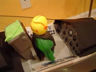
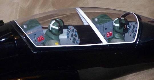
33 Some Cockpit images: Page 33 of 47


34 Rear Hatch Attachment: I chose to use strong magnets for the canopy hold downs. I also did the same for the rear hatch. 1 Epoxy pieces of scrap balsa block at the four corners of the rear hatch. Some shaping and fitting will be required before final gluing. 2 Recess and epoxy a rare earth magnet into each block so that it is flush with the fuselage when the hatch is attached. 3 Install mating magnets on the fuselage side and reinforce (from the backside) with epoxy/filler to hold them in place. Page 34 of 47


35 Retractable Landing Gear: Nose Install 1 Cut out the nose door outline at the front (underside) of the fuse. Follow the panel lines plus 15mm at the rear of the door. 2 Assemble the nose gear mounting formers as shown. Page 35 of 47


36 3 The nose strut should be angled up when viewed from the side. 4 Mount the retract base to the formers before gluing in place in the fuselage. 5 With the strut inserted and the gear in the down position. Position the formers in the fuselage so that the strut just clears the rear edge of the door and make certain that you can access the screws to remove the retract from the mounting plate. 6 Glue the formers to the fuselage using slow cure epoxy and microballoons. 7 Bend your nose strut so that when your gear is retracted, the nose wheel has 1-2mm clearance with the front edge of the door opening. This will help maintain a level-to-slightly nose up attitude when the mains are installed. Page 36 of 47

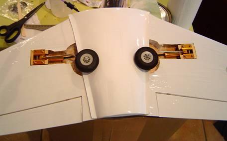
37 Retractable Landing Gear: Main Gear Install 1 Look at the image below to see where the center of your struts should be with the gear in the down position. 2 Place a protective layer of masking tape on the underside of the wing in the general locations of the strut centers. 3 Place the retract bases at the noted locations using the strut centers as your reference point and trace the outline of the retract bases onto the wing. 4 Align the supplied wheel well template with your previous tracing and trace the well outline onto the wing. Page 37 of 47
38 Page 38 of 47


39 5 Using a sharp blade carefully cut the outline away. You want to cut through the covering and the top wood skin. 6 If there is foam from the wing core in your pocket, remove it. 7 Reinforce the area in the wing where the retract bases will go. I used 2 layers of 3oz glass cloth squares. 8 Mounting plates are provided for the retract mains, but you will need to build offset supports before attaching the mains to the wing. 9 Using some hardwood blocks, I cut off sections to match the retract mains mounting plates. They are glued to the plate and act as standoff s for the retract mains. 10 The plate/blocks structure and retract gets glued into the wing. Wrap the retract base in cling film and secure it to the mount before final gluing into the wing. TIP: Insert your unbent wire struts before the glue fully sets, retract them and make sure the struts point to each other. 11 If using wire struts, follow the bend guidelines provided. WARNING: The strut centers are very close to the CG, so bent leg struts are highly recommended. Page 39 of 47


40 Page 40 of 47


41 Retractable Landing Gear: Steering Servo Install (pull-pull) There are numerous ways to install your steering servo. I chose to position my steering servo between the retracted nose wheel and the front of the retract cylinder, mounted to the top of the fuselage nose. I fabricated a mount for my servo that allows me to remove the servo for maintenance. 1 Using some scrap balsa blocks, I constructed a mount that holds my servo in a vertical orientation. 2 The mount is then glued with epoxy to the ceiling of the fuselage. 3 With the gear down, pull lines are then attached to the servo arm ends and to the steering arm. Page 41 of 47

42 General Component Placement and Center of Gravity Note: The CG pictured below is safely forward. You will need some up elevator trim at the specified balance point. This CG is recommended for your first flights; you can move it back as you become familiar with the aircraft. You should balance the ready to fly aircraft upside down at the indicated position. If you have retracts, put them in the gear down position before balancing. The attitude of the aircraft should be level to slightly nose down. Page 42 of 47


43 Without your battery, chances are your build will be tail heavy with everything installed. Your battery (and battery tray) should be located so that your craft balances at the stated center of gravity. The images below show where I chose to locate certain components. Retract air tank, valve and servo in Battery and tray ESC mounted up under rear hatch vents. Receiver at the back of rear hatch opening, attached to sidewalls with Velcro. Page 43 of 47
44 Test Flight * Before the first flights input 2 to 3 clicks of up elevator trim. Runway takeoff roll should be between 150 and 200 feet, depending on the weight of your aircraft and power system. Takeoffs should be into the wind (if any) at full throttle. Roll on throttle and build up speed after about 150 feet, smoothly apply a small amount of up elevator. Keep your climb out gentle and gain altitude (2 to 3 mistakes high), retract your gear if you wish and trim the aircraft at ¾ throttle. Make a few gentle circuits to adjust to the models handling, keep your turns large and smooth. At altitude check the stall of the aircraft, and practice slow flight to become familiar with the aircrafts slow speed handling. Landings are best executed with a little throttle. With throttle between ¼- ½, control your descent with throttle and use elevator to flair 1 to 2 feet above the runway. Bungee assisted launches can be done with a ramp, rail or dolly setup. Setup your bungee pull tension to equal 5-6 times the models ready to fly weight. Page 44 of 47

45 Page 45 of 47
46 Page 46 of 47
47 Page 47 of 47
Turbinator-2 Build Manual
 Turbinator-2 Build Manual Thank you for your purchase of the Turbinator-2 sport jet by Boomerang RC Jets. This RC Jet IS NOT A TOY and should only be flown and operated by experienced RC Turbine Pilots.
Please read all instructions carefully before assembly and flight!
 Please read all instructions carefully before assembly and flight! Thank you for purchasing the Mig-15. This model is designed for the intermediate to advanced flyer. The model is receiver ready and includes
I n s t r u c t i o n M a n u a l. Instruction Manual SPECIFICATION
 I n s t r u c t i o n M a n u a l Instruction Manual SPECIFICATION - Wingspan: 3200mm (125,9 in) - Length: 1650mm (64,9 in) - Flying weight: 3000gr 3200gr - Wing area: 64.5 dm2 - Wing loading: 46g/dm2
STORCH. Parts. Additional items needed to complete the Storch
 STORCH Parts Fuse with Greenhouse- (Attached) Left and right wing panel Horizontal and vertical stab 2 Wing center blocks 2 Carbon spares for wing 1 Undercarriage with wheels 2 Undercarriage shocks 2 Carbon
51in Aerobatic Series Sukhoi SU-26M Almost-Ready-to-Fly. Instruction Manual. Specifications
 51in Aerobatic Series Sukhoi SU-26M Almost-Ready-to-Fly Instruction Manual Specifications Wingspan: 51.2 in (1300mm) Length: 51.2 in (1300mm) Wing Area: 581 sq in (37.5sq dm) Flying Weight: 3.5 lb (1600g)
RECOMMENDED MOTOR AND BATTERY SET UP
 SPECIFICATION - Wingspan: 6000mm (236.2 in) - Length: 2873mm (113.1 in) - Flying weight: 14-18 kg - Wing area: 219.4 dm2 - Wing loading: 64g/dm2 - Wing type: HQ airfoils - Covering type: Genuine ORACOVER
Assembly and Operating Manual. SPECIFICATION Length inch (640mm) Wing Span inch (705mm) Flying Weight oz (330g)
 Wing Span inch (705mm) Flying Weight oz (330g)") Assembly and Operating Manual SPECIFICATION Length 25.19 inch (640mm) Wing Span 27.76 inch (705mm) Flying Weight 11.64 oz (330g) Dear customer, Assembly and Operating manual VIPER The Radio Control System
Assembly and Operating Manual SPECIFICATION Length 25.19 inch (640mm) Wing Span 27.76 inch (705mm) Flying Weight 11.64 oz (330g) Dear customer, Assembly and Operating manual VIPER The Radio Control System
MiG-29 Retract Kit (for the HET-RC Mini Air Retract System)
") MiG-29 Retract Kit (for the HET-RC Mini Air Retract System) The MiG-29 Retract Kit was designed to allow the easy installation of the HET-RC mini Air Retract system into the twin EDF MiG-29. We recommend
MiG-29 Retract Kit (for the HET-RC Mini Air Retract System) The MiG-29 Retract Kit was designed to allow the easy installation of the HET-RC mini Air Retract system into the twin EDF MiG-29. We recommend
FUN-50 ARF ASSEMBLY MANUAL
 FUN-50 ARF ASSEMBLY MANUAL This Manuel is the sole property of Kangke Industrial USA, Inc. Reproducing any part without the consent of Kangke Industrial USA, Inc. is a lawful violation. Kangke Industrial
RADIO CONTROL MODEL HURRICANE
 RADIO CONTROL MODEL VQAA040G VQAA040B HURRINE Almost ready to fly SPECIFITIONS Wingspan...63 in. / 161cm Length...50 in. / 129cm Engine...50~60 2T / 70~90 4T Or Electric equivalent. RC Functions: Motor
STICK F Class 60 Class INSTRUCTION MANUAL. Or Electric equivalent. (2T engine) (4T engine) Radio control model SPECIFICATIONS
 (4T engine) Radio control model SPECIFICATIONS") Radio control model 45 Class 60 Class (2T engine) (4T engine) Or Electric equivalent INSTRUCTION MANUAL STICK F - 1500 SPECIFICATIONS Wingspan 60 in. Length 38.5 in. Electric Motor 650 Watt Glow Engine.45
Radio control model 45 Class 60 Class (2T engine) (4T engine) Or Electric equivalent INSTRUCTION MANUAL STICK F - 1500 SPECIFICATIONS Wingspan 60 in. Length 38.5 in. Electric Motor 650 Watt Glow Engine.45
Flyzone Spitfire FF to R/C Conversion Instructions
 Flyzone Spitfire FF to R/C Conversion Instructions Hobbico Flyzone EP FF airplanes have been around for years, with exciting new models being added constantly. The recent interest shown by R/C modelers
Please read all instructions carefully before assembly and flight!
 c c Please read all instructions carefully before assembly and flight! Thank you for purchasing the. This model is designed for the intermediate to advanced flyer. The model is receiver-ready and includes
RECOMMENDED MOTOR AND BATTERY SET UP
 SPECIFICATION - Wingspan: 1410mm (55.5 in) - Length: 1278mm (50.3 in) - Flying weight: 3.2-3.4 kg - Wing area: 41.3 dm2 - Wing loading: 75g/dm2 - Wing type: Naca airfoils - Covering type: Genuine ORACOVER
RECOMMENDED MOTOR AND BATTERY SET UP
 SPECIFICATION - Wingspan: 1404mm (55.3in) - Length: 1134mm (44. 6 in) - Flying weight: 3.2-3.4 kg - Covering type: Genuine ORACOVER - Spinner size: scale type (not included) - Radio: 4 channel minimum
I/C FLIGHT GUIDELINES
 SPECIFICATION - Wingspan: 3500mm (137.8 in) - Length: 1650mm (64.96 in) - Flying weight: 3700-4000 gr - Wing area: 75 dm2 - Wing loading: 49g/dm2 - Wing type: HQ profile - Covering type: Genuine ORACOVER
Table of Contents. Tail Wheel Assembly Installation.. page 01. Stabilizer Installation.. page 02. Fin Installation.. page 03
 Table of Contents Tail Wheel Assembly Installation.. page 01 Stabilizer Installation.. page 02 Fin Installation.. page 03 Elevator and Rudder Hinge Installation.. page 04 Rudder Controls.. page 05 Elevator
the leading edge of the wing, at the fuselage - Length: 1540mm (60.6 in) 10% expo; High: 15mm up/down, 10% expo - Wing area: 40dm2
 10% expo; High: 15mm up/down, 10% expo - Wing area: 40dm2") SPECIFICATION - Gravity CG: 165-170 mm (6.5-6.7 in) Back from - Wingspan: 1400mm (55.1 in) the leading edge of the wing, at the fuselage - Length: 1540mm (60.6 in) - Control throw Ailerons: Low: 12mm up/down,
SPECIFICATION - Gravity CG: 165-170 mm (6.5-6.7 in) Back from - Wingspan: 1400mm (55.1 in) the leading edge of the wing, at the fuselage - Length: 1540mm (60.6 in) - Control throw Ailerons: Low: 12mm up/down,
SU-31 PROFILE ELECTRIC ARF ASSEMBLY MANUAL
 SU-31 PROFILE ELECTRIC ARF ASSEMBLY MANUAL 1 TABLE OF CONTENTS Page Aeroworks Contact Information... 3 Introduction.. 4 Kit Contents... 5 Items needed to complete 6 Wing Assembly. 7 Stab Assembly. 10 Flight
Instruction Manual. Wingspan : 1400 mm (55.12 inch) : 1480 mm (58.27 inch) : 5500gr gr. : 6-9 channel/ 8 servo high torque,1 standard
 : 1480 mm (58.27 inch) : 5500gr gr. : 6-9 channel/ 8 servo high torque,1 standard") Wingspan : 1400 mm (55.12 inch) g Length : 1480 mm (58.27 inch) Weight : 5500gr - 6000gr Radio : 6-9 channel/ 8 servo high torque,1 standard Engine : GT 22 OS KIT CONTENTS: We have organized the parts
Wingspan : 1400 mm (55.12 inch) g Length : 1480 mm (58.27 inch) Weight : 5500gr - 6000gr Radio : 6-9 channel/ 8 servo high torque,1 standard Engine : GT 22 OS KIT CONTENTS: We have organized the parts
Aviator Pro 120 ARF. Instruction Manual. Specifications
 Aviator Pro 120 ARF Instruction Manual Specifications Wingspan: 110 in (2800 mm) Length: 74 in (1870 mm) Wing Area: 1581sq in (102 sq dm) Weight: 11.4-13.4 lbs (5190-6100 g) Dear Customer, Congratulations
EXTRA 330LX. Specifications: Code: SEA274. Graphics and specifications may change without notice. ASSEMBLY MANUAL
 ASSEMBLY MANUAL EXTRA 330LX Code: SEA274 Graphics and specifications may change without notice. Specifications: Wingspan---------------82.0 in (208.2 cm). Wing area---------------1349.4 sq.in ( 87.1 sq.dm).
Flyzone P-40 FF to R/C Conversion Instructions
 Flyzone P-40 FF to R/C Conversion Instructions Hobbico Flyzone EP FF airplanes have been around for years, with exciting new models being added constantly. The recent interest shown by R/C modelers in
Trainer Assembly Manual
 Trainer Assembly Manual www.pilot-rc.com -Pilot Trainer- 1 -Pilot Trainer- 2 -Pilot Trainer- 3 -Preliminary i wing & stab assembly- 1-) Locate both Plywood wing joiners (Large and small one) 2-) Insert
96in Super Decathlon ARF
 96in Super Decathlon ARF Instruction Manual Specifications Wingspan: 96in (2438mm) Length: 63.5 in (1614mm) Weight: Approx. 13lbs (6.5kg) 1 Dear Customer, Congratulations on your purchase of Super Decathlon
SIZE.120 OR 30CC SCALE 1:5 ARF
 PC21 PILATUS MK2 SIZE.120 OR 30CC SCALE 1:5 ARF SPECIFICATION - Wingspan: 1772mm (69.72in) - Length: 2019mm (79.5 in) - Flying weight: 6.4-7.2 kg - Wing area: 57.6 dm2 - Wing loading: 113g/dm2 - Wing type:
Dassault Aviation FALCON 7 X. for Jet CAT P160. Assembly Manual. AVIATION Design
 Dassault Aviation FALCON 7 X for Jet CAT P160 Assembly Manual AVIATION Design ZI le chenet, 91490 Milly La Foret, FRANCE Tel : 33 1 64 98 93 93 Fax : 33 1 64 98 93 88 E-mail : aviation.design@wanadoo.fr
RECOMMENDED EDF AND BATTERY SET UP
 SPECIFICATION - Wingspan: 1150mm (45.3 in) - Length: 1587mm (62.5 in) - Flying weight: 5.0-5.3 kg - Wing area: 40dm2 - Wing loading: 125g/dm2 - Wing type: Naca airfoils - Covering type: Genuine ORACOVER
Instruction Manual. Specification:
 Instruction Manual L O W Specification: Wingspan: 133 cm (52.3 inches) Length : 104 cm (40.9 inches) Weight : 1790gr Engine : 25-32 two stroke Radio : 4 channel - 4 servo W I N G KIT CONTENTS: We have
35MM Series Nano F15. Assembly and Operating Manual
 35MM Series 2011 Assembly and Operating Manual SPECIFICATION: Length: 21-3/5"(550mm) Wing Span: 15-3/5"(395mm) Flying Weight: 5-4/5oz (165g.) Nano F15 Dear customer, Congratulations on your choice of a
MARACANA ASSEMBLY INSTRUCTION .40 ARF LOW WING TRAINER RADIO CONTROL MODEL. Every body can fly
 RADIO CONTROL MODEL ASSEMBLY INSTRUCTION MARACANA.40 ARF LOW WING TRAINER Every body can fly VQA085 EP GP You can use both Gas or Electric power Wingspan: 59in.(1520mm) Fuselage length: 48in.(1220mm) Engine:
PilotRC Trainer USER MANUAL
 PilotRC Trainer USER MANUAL Introduction Thank you for purchasing our Trainer plane. we strive to achieve a good quality quick build ARF aircraft. It requires the least amount of assembly of any ARF kit
RECOMMENDED MOTOR AND BATTERY SET UP
 SPECIFICATION - Wingspan: 2000mm (78.7in) - Length: 1544mm (60.7 in) - Flying weight: 3600-3800 gr - Wing area: 66 dm2 - Wing loading: 55g/dm2 - Wing type: Naca airfoils - Covering type: Genuine ORACOVER
HIGH WING MK2 GP/EP ARF SCALE
 SONIC HIGH WING MK2 GP/EP.25-.32 ARF SCALE 1:10 SPECIFICATION - Wingspan: 1340mm (52.7in) - Length: 1040mm (40.9 in) - Flying weight: 1800-2000 gr - Wing area: 27 dm2 - Wing loading: 79g/dm2 - Wing type:
PITTS 12 R/C SPORT-SCALE AIRCRAFT ASSEMBLY AND INSTRUCTION MANUAL. Copyright Century UK Limited 2012
 PITTS 12 R/C SPORT-SCALE AIRCRAFT ASSEMBLY AND INSTRUCTION MANUAL 1 Warning: This radio controlled model is not a toy. It requires skill to fly and is not recommended for use by beginners. It should not
Instruction Manual book
 book ITEM CODE:BH 115. SPECIFICATION Wingspan : 6,000 mm 236,22 in. Length : 2,740 mm 107,87 in. Weight : 17.5kg 38.5Lbs. Radio : 08 channels. Servo : 07-08 HS-5685MH(HITEC) Battery : 2 Cells-Li-Po 7.4V
Strix Goblin Instruction Manual. Rev
 Strix Goblin Instruction Manual Rev 3-4.24.2017 1 Introduction Thank you for purchasing the Strix Goblin! This is a high performance plank style aircraft and it was designed using aerodynamic principles
MS:159 ASSEMBLY MANUAL. Graphics and specifications may change without notice.
 ASSEMBLY MANUAL MS:159 Graphics and specifications may change without notice. Specifications: Wing span ----------------------------61.8in (157cm). Wing area -----------------1100.5sq.in (71.0sq dm). Weight
RECOMMENDED MOTOR AND BATTERY SET UP
 SPECIFICATION - Wingspan: 1800mm (70.8 in) - Length: 1355mm (53.3 in) - Flying weight: 4100-4300 g - Wing area: 51 dm2 - Wing loading: 80g/dm2 - Wing type: Naca airfoils - Covering type: Genuine ORACOVER
Assembly and operating instructions. Assembly and Operating Manual
 Assembly and operating instructions Assembly and Operating Manual Dear customer, Assembly and Operating Manual The radio control system Glued joints, suitable adhesives Congratulations on your choice of
Radio control model INSTRUCTION MANUAL PYLON RACING. Wingspan: 1148mm (45.2 ) Radio : 4 channels Engine : two-stroke
 Radio : 4 channels Engine : two-stroke") VQA038 VQA039 Radio control model INSTRUCTION MANUAL MAGIC PYLON RACING Wingspan: 1148mm (45.2 ) Radio : 4 channels Engine :.25 -.32 two-stroke WARNING! This radio control model is not a toy. If modified
VQA038 VQA039 Radio control model INSTRUCTION MANUAL MAGIC PYLON RACING Wingspan: 1148mm (45.2 ) Radio : 4 channels Engine :.25 -.32 two-stroke WARNING! This radio control model is not a toy. If modified
INSTRUCTION MANUAL BOOK
 INSTRUCTION MANUAL BOOK ITEM CODE BH57. SPECIFICATION Wingspan: 1,470 mm. 57.87 in. Length : 1,180 mm. 46.46 in. Weight : 2.7 Kg. 5.94 Lbs. Engine : 46 cu.in 2 stroke. 52 cu.in 4 stroke. Radio : 4 channels.
Assembly Manual. Version 01/01/2006
 Assembly Manual ZI le chenet, 91490 Milly La Foret, FRANCE Tel : 33 1 64 98 93 93 Fax : 33 1 64 98 93 88 E-mail : aviation.design@wanadoo.fr www.adjets.com Version 01/01/2006 INTRODUCTION is our new jet
Instruction Manual book
 Instruction Manual book Item code:bh133 SPECIFICATION Wingspan : 1,400 mm 55.12 in. Length : 1,350 mm 53.15 in. Weight : 3.7 kg 8.14 Lbs. Radio : 08-09 channels. Servo : 08-09 servos. EDF : Turingy SK3
SK-50 ARF ASSEMBLY MANUAL
 SK-50 ARF ASSEMBLY MANUAL Kangke Industrial USA, Inc. 65 East Jefryn Blvd. Deer Park NY 11729 http://www.kangkeusa.com E-mail: info@kangkeusa.com Tel: 1-877-203-2377 Fax: 1-631-274-3296 Congratulations!
: 7 channel - 9 servo, Hi-Torque ( Minimum 6 kg ).
.") g Wingspan : 1820mm (71.65 inches) Length : 1625mm (63.98 inches) Weight : 6900gr Engine : 25cc - 35cc Radio : 7 channel - 9 servo, Hi-Torque ( Minimum 6 kg ). KIT CONTENTS: We have organized the parts
g Wingspan : 1820mm (71.65 inches) Length : 1625mm (63.98 inches) Weight : 6900gr Engine : 25cc - 35cc Radio : 7 channel - 9 servo, Hi-Torque ( Minimum 6 kg ). KIT CONTENTS: We have organized the parts
to fly. Most hardware included and all replacement parts are available.
 Instruction Manual The Thunderbolt P47 was perhaps the greatest of world war II in terms of all round performance and capability Phoenix Model has recreated a 2C - 60 class engine (or 4c 91 class) It was
RECOMMENDED MOTOR AND BATTERY SET UP
 SPECIFICATION - Wingspan: 1600mm (63 in) - Length: 1285mm (50.5 in) - Flying weight: 2800-3200 gr - Wing area: 40.1 dm2 - Wing loading: 78g/dm2 - Wing type: Naca airfoils - Covering type: Genuine ORACOVER
Instruction Manual book
 book ITEM CODE:BH 139 SPECIFICATION Wingspan : 1,450mm 57.09 in. Length : 1,140 mm 44.88 in. Weight : 3.3kg 7.26 Lbs. Radio : 05 channels. Servo : 07 mini servos+ 3servos Retracts (FUTABA S3170G) EDF:
RECOMMENDED MOTOR AND BATTERY SET UP
 SPECIFICATION - Wingspan: 2190mm (86.2 in) - Length: 1907mm (75 in) - Flying weight: 9000-12000 gr - Wing area: 92 dm2 - Wing loading: 98g/dm2 - Wing type: Naca airfoils - Retract gear type: Air-retract
MS:176 ASSEMBLY MANUAL. Graphics and specifications may change without notice.
 ASSEMBLY MANUAL MS:176 Graphics and specifications may change without notice. Specifications: Wing span ------------------------------98.4in (250cm). Wing area ----------------1576.4sq.in (101.7sq dm).
Assembly and operating instructions. Assembly and Operating Manual
 Assembly and operating instructions Assembly and Operating Manual Dear customer, Assembly and Operating Manual The radio control system Glued joints, suitable adhesives Congratulations on your choice of
Assembly and Operating Manual HR-100. Specification: *Length: 41-7/10"(1060 mm) *Wing span: 49-1/5"(1250 mm) *Flying weight: 45.
 *Wing span: 49-1/5(1250 mm) *Flying weight: 45.") Assembly and Operating Manual HR-100 Specification: *Length: 41-7/10"(1060 mm) *Wing span: 49-1/5"(1250 mm) *Flying weight: 45.9 oz (1300g) Dear customer, Congratulations on your choice of a factory-assembled
Assembly and Operating Manual HR-100 Specification: *Length: 41-7/10"(1060 mm) *Wing span: 49-1/5"(1250 mm) *Flying weight: 45.9 oz (1300g) Dear customer, Congratulations on your choice of a factory-assembled
AVIATOR 25 ARF Almost Ready-to-Fly
 AVIATOR 25 ARF Almost Ready-to-Fly Instruction Manual Specifications Wingspan: 54.3 in (1380mm) Length: 45.2 in (1150mm) Wing Area: 438 sq in (34sq dm) Flying Weight: 3.8 b (1700g) Dear Customer, Congratulations
MS:183 ASSEMBLY MANUAL. Graphics and specifications may change without notice.
 MS:183 ASSEMBLY MANUAL Graphics and specifications may change without notice. Specifications: Wing span ------------------------------79.9in (203cm). Wing area -----------------1165.6sq.in (75.2sq dm).
8mm EPP Acrocub. Instruction Manual. Specifications
 8mm EPP Acrocub Instruction Manual Specifications Wingspan: 34.6 in (880mm) Length: 31.5 in (800mm) Wing Area: 213.9 sq in (13.8sq dm) Flying Weight: Approx. 9oz (270g) Dear Customer, www.valuehobby.com/8mm-epp-acrocub.html
Assembly Manual For. Wingspan: 88 in Wing area: sp in Length: 78.8 in Engine: 50CC.
 Assembly Manual For Wingspan: 88 in Wing area: 1479.8 sp in Length: 78.8 in Engine: 50CC www.pilot-rc.com INTRODUCTION Thank you for purchasing our new 50 cc model. We strive to bring you the most complete
Instruction Manual book
 book SPECIFICATION Wingspan : 1,450 mm 57.09 in. Length : 1,200mm 47.24in. Weight : 3.1 kg 6.82 Lbs. Radio : 05 channels. Servo : 07 servos. Engine : 61-75 2 stroke. 91 4 stroke. Made in Vietnam. This
F-84G ThunderJet Construction Manual. Introduction
 Introduction Thank you for purchasing the PST Jets F-84G ThunderJet kit. The PST F-84G is designed for use with 20 to 30 lb turbine engines. The PST F-84G is based on an accurate scale outline of the Republic
Lanier R/C F-4 Phantom
 Lanier R/C.40-.46 F-4 Phantom Almost Ready to Fly WARNING! THIS IS NOT A TOY! THIS IS NOT A BEGINNERS AIRPLANE This R/C kit and the model you will build from it is not a toy! It is capable of serious bodily
F3P Instruction Manual
 Before use, please read the explanations carefully! F3P Instruction Manual Specifications Fuselage length: 884mm ( 34. Bin ) Wingspan : 845mm ( 33. 2in) Flying Weight : 135-160g (with battery) Additional
1660mm (65.4 in) 1200mm (47.2 in) 2700gr gr 6 channel - 7 servo standard 46/ 2 stroke or 52/ 4 stroke
 1200mm (47.2 in) 2700gr gr 6 channel - 7 servo standard 46/ 2 stroke or 52/ 4 stroke") Instruction Manual CESSNA-46 1660mm (65.4 in) 1200mm (47.2 in) 2700gr - 3000gr 6 channel - 7 servo standard 46/ 2 stroke or 52/ 4 stroke KIT CONTENTS: We have organized the parts as they come out of the
Instruction Manual CESSNA-46 1660mm (65.4 in) 1200mm (47.2 in) 2700gr - 3000gr 6 channel - 7 servo standard 46/ 2 stroke or 52/ 4 stroke KIT CONTENTS: We have organized the parts as they come out of the
This manual is for all versions of the F9F Panther This Manual uses one color scheme as an example
 This manual is for all versions of the This Manual uses one color scheme as an example Thank you for purchasing the. This model is designed for the intermediate to advanced flyer. The model is receiver-ready
Instruction Manual. Wingspan : 2270mm (89.37 inches) : 1870mm (73.62 inches) : 7400gr gr. : 4 channel - 6 standard servo.
 : 1870mm (73.62 inches) : 7400gr gr. : 4 channel - 6 standard servo.") Wingspan : 2270mm (89.37 inches) g Length : 1870mm (73.62 inches) Weight : 7400gr - 7600gr Radio : 4 channel - 6 standard servo Engine : 25cc-35cc KIT CONTENTS: We have organized the parts as they come
Wingspan : 2270mm (89.37 inches) g Length : 1870mm (73.62 inches) Weight : 7400gr - 7600gr Radio : 4 channel - 6 standard servo Engine : 25cc-35cc KIT CONTENTS: We have organized the parts as they come
Instruction Manual book
 book SPECIFICATION Wingspan : 1,920 mm 75.59 in. Length : 1,560 mm 61.42 in. Weight : 5 kg 11.00Lbs. Radio : 06 channels. Servo : 09 servos. Engine : 120 4 stroke. Made in Vietnam. This instruction manual
SBACH SCALE 1:4 ½ ARF
 SPECIFICATION - Wingspan: 1663mm (65.5 in) - Length: 1638mm (64.5 in) - Flying weight: 4700-5200 gr - Wing area: 56 dm2 - Wing loading: 85g/dm2 - Wing type: Naca airfoils - Covering type: Genuine ORACOVER
Assembly and Operating Manual
 Assembly and Operating Manual Dear customer, Congratulations on your choice of a factory-assembled model aircraft from the SKYANGEL Hummingbird range and thank you for placing your trust in us. Very little
Instruction Manual book
 Instruction Manual book Item code:bh144 SPECIFICATION Wingspan : 1,400 mm 55.12 in. Length : 1,350 mm 53.15 in. Weight : 4 kg 8.8 Lbs. Empty Weight: 1.9 kg 4.18 lbs Radio : 08 channels. Servo : 08 size
Instruction Manual book
 Instruction Manual book SPECIFICATION Wingspan : 1,800mm. 70.87 in. Length : 1,350 mm. 53.15in. Weight : 3.6kg. 7.92lbs. Parts Listing required (not included). Glow Engine : 55-61 2 stroke. 91 4 stroke.
Instruction Manual. Wingspan : 1670mm. : 3400gr gr. : 61/75 two stroke. : 5 servo + 1 servo retract / 6 channel
 Wingspan : 1670mm g Length Weight Engine Radio : 1350mm : 3400gr - 4000gr : 61/75 two stroke : 5 servo + 1 servo retract / 6 channel KIT CONTENTS: We have organized the parts as they come out of the box
Instruction Manual book
 book (pusher propeller) ITEM CODE:BH 142 SPECIFICATION Wingspan : 1,450mm 57.09 in. Length : 1,165 mm 45.87 in. Weight : 3.3kg 7.26 Lbs. Radio : 05 channels. Servo : 07 size (29 x 13 x 30) mm. Electric
RECOMMENDED MOTOR AND BATTERY SET UP
 SPECIFICATION - Wingspan: 1420mm (55.91 in) - Length: 1370mm (53.94 in) - Flying weight: 2600-2800 gr - Wing area: 41.6 dm2 - Wing loading: 65g/dm2 - Wing type: Naca airfoils - Covering type: Genuine ORACOVER
RADIO CONTROL MODEL ASSEMBLY INSTRUCTIONS. Wasp
 RADIO CONTROL MODEL ASSEMBLY INSTRUCTIONS Wasp TRAINER Almost ready-to-fly Wingspan 1520mm Fuselage length 1105mm Engine: 40-46 2T / 52-60 4T Electric Motor: 600-700W Radio: 5 channel / 4-5 servo RC Functions:
Instruction Manual. Specifications are subjected to change without notice due to product continuous improvements.
 Instruction Manual Specifications are subjected to change without notice due to product continuous improvements. 1 The Wargo Signature Yak 55 is the realization of my goal to have the perfect 3D and aerobatic
Assembly and Operating Manual
 Dear customer, Assembly and Operating Manual The radio control system Glued joints, suitable adhesives Congratulations on your choice of a factory-assembled model aircraft from the SKYANGEL Hummingbird
29% KATANA ARF ASSEMBLY MANUAL
 29% KATANA ARF ASSEMBLY MANUAL Required but not included Aircraft Specifications: 4 channel radio and supporting equipment Wing Span 84 Engine 3.2-4.2 c.i. (50-60 c.c.) Wing Area 1270 Sq. in. Fuel Tank
Instruction Manual. Wingspan : 1884 mm (74.17 in) Length. Weight. Engine. : 4 channels / 5 servo standard. : 1450 mm (57.
 Length. Weight. Engine. : 4 channels / 5 servo standard. : 1450 mm (57.") Wingspan : 1884 mm (74.17 in) Length : 1450 mm (57.09 in) Weight : 4000 gr Engine : 60 two strokes Radio : 4 channels / 5 servo standard KIT CONTENTS: We have organized the parts as they come out of the
Wingspan : 1884 mm (74.17 in) Length : 1450 mm (57.09 in) Weight : 4000 gr Engine : 60 two strokes Radio : 4 channels / 5 servo standard KIT CONTENTS: We have organized the parts as they come out of the
Instruction Manual book
 Instruction Manual book SPECIFICATION Wingspan : 1,920 mm 75.59 in. Length : 1,560 mm 61.42 in. Weight : 5 kg 11.00Lbs. Radio : 06 channels. Servo : 09 servos. Engine : 120 4 stroke. Made in Vietnam. JU87-STUKA
Instruction Manual. SkyRacer. IMAA Legal Sport Aircraft For 35cc - 62cc size engines 84 Wingspan
 Instruction Manual SkyRacer IMAA Legal Sport Aircraft For 35cc - 62cc size engines 84 Wingspan Eureka Aircraft Warranty Eureka Aircraft guarantees this kit to be free from defects in both material and
HERO 3D SCALE 1:6 ARF
 Instruction Manual SPECIFICATION - Wingspan: 1500mm(59 in) - Length: 1410mm (55.5 in) - Flying weight: 2100-2300 gr - Wing area: 58 dm2 - Wing loading: 39g/dm2 - Covering type: Genuine ORACOVER - Gear
: 6 channel - 9 servo
 g Wingspan : 2005mm (78.94 inches) Length : 1640mm (64.57 inches) Weight : 6400g - 6600g Engine : 25cc - 35cc Radio : 6 channel - 9 servo KIT CONTENTS: We have organized the parts as they come out of
Supermarine Sparrow I 36 R/C Scale Model Instructions
 Supermarine Sparrow I 36 R/C Scale Model Instructions CONTACT INFORMATION Designed by: M.K. Bengtson Prototype Builder: Mike Stanley Manufactured and Distributed by: Bengtson Company e-mail: sales@aerodromerc.com
REVISION DESCRIPTION:
 REVISION DESCRIPTION: 1) Page: 12-03 REV 1: Step 1: and Figure 1: Final-Drill s.b. Match-Drill. Step 4: Updated flox mixture description to match later description (removed "peanut butter-like" description).
SBD DAUNTLESS GP/EP SIZE ARF SCALE 1:8. Instruction Manual
 GP/EP SIZE.46-.55 ARF SCALE 1:8 SPECIFICATION - Wingspan: 1440mm (56.7in) - Length: 1140mm (44.9 in) - Flying weight: 3000-3300 g - Wing area: 42 dm2 - Wing loading: 78g/dm2 - Wing type: Naca airfoils
Instruction Manual book
 Instruction Manual book ITEM CODE: BH56. SPECIFICATION Wingspan : 1,660 mm 65.35 in. Length : 1,420 mm 55.91 in. Weight : 3.8 kg 8.36 Lbs. Radio : 06 channels. Servo : 08 servos. Engine : 75 Cu.in 2 Stroke.
F3D-30 ARF ASSEMBLY MANUAL
 F3D-30 ARF ASSEMBLY MANUAL This Manuel is the sole property of Kangke Industrial USA, Inc. Reproducing any part without the consent of Kangke Industrial USA, Inc. is a lawful violation. Kangke Industrial
Neptune Seaplane25 ARF. Instruction Manual. Specifications
 Neptune Seaplane25 ARF Instruction Manual Specifications Wingspan: 1270mm (50in) Length: 1155mm (45.5in) Wing Area: 34.8 sq dm (539.4 sq in) Weight: 1950g (4.30lbs) Product Highlights Removable hatch on
Instruction Manual book
 Instruction Manual book ITEM CODE: BH39. SPECIFICATION Wingspan : 181 cm 71.26 inches. Length : 155 cm 61.024 inches. Weight : 04 kg 8.8 lbs. Servo : 9 servos. Radio : 6 channels. Engine : 91 cu.in - 2
Instruction Manual book
 Instruction Manual book SPECIFICATION Wingspan : 1,920 mm 75.59 in. Length : 1,560 mm 61.42 in. Weight : 5 kg 11.00Lbs. Radio : 06 channels. Servo : 09 servos. Engine : 120 4 stroke. Made in Vietnam. JU87-STUKA
STEP 1 - APPLYING HINGE BEVELS TO FRONT WING, REAR WING, VERTICAL STABILIZER, AND RUDDER FRONT WING (UNDERSIDE) 45 DOUBLE HINGE BEVEL
 45 DOUBLE HINGE BEVEL") SkyRaiderv.b WING SPAN: FRONT - 22 in. REAR - 28.5 in. LENGTH: 35.25" WING AREA: 381 sqin. WEIGHT: 19-20oz. (RECOMMENDED) POWER: HACKER A20-20L, 10x3.8 APC PROP, 3S1P 1320mah Lipo 15C, 20A ESC RADIO: 4
SkyRaiderv.b WING SPAN: FRONT - 22 in. REAR - 28.5 in. LENGTH: 35.25" WING AREA: 381 sqin. WEIGHT: 19-20oz. (RECOMMENDED) POWER: HACKER A20-20L, 10x3.8 APC PROP, 3S1P 1320mah Lipo 15C, 20A ESC RADIO: 4
Instruction Manual book
 Instruction Manual book ITEM CODE:BH118. SPECIFICATION Wingspan : 1,050 mm 41.34 inches. Length : 950mm 37.4 inches. Weight : 1 kg 2.2 lbs. Radio : 04 channels. Servo : 4 mini servos. Motor : BL2215/20
Instruction Manual book
 Instruction Manual book SPECIFICATION Wingspan : 1,780 mm 70.08 in. Length : 1,520 mm 59.84 in. Weight : 4.8 kg 10.56 Lbs. Radio : 06 channels. Servo : 09 servos. Engine : 120 4stroke Made in Vietnam.
YAK 54 Aerobatic Model Aircraft Assembly and Instruction Manual
 YAK 54 Aerobatic Model Aircraft Assembly and Instruction Manual Warning: This radio controlled model is not a toy. It requires skill to fly and is not recommended for the novice pilot. It should not be
RECOMMENDED MOTOR AND BATTERY SET UP
 SPECIFICATION - Wingspan: 1669mm (65.7in) - Length: 1229mm (48.43 in) - Flying weight: 3300-3400 gr - Wing area: 44.2 dm2 - Wing loading: 67g/dm2 - Wing type: Naca airfoils - Covering type: Genuine ORACOVER
Instruction Manual. Wingspan : 1694mm (66.69 in) : 1470mm (57.87 in) : 3200gr gr. : 61 two stroke/ 71 four stroke. : 6 channel / 7 servo
 : 1470mm (57.87 in) : 3200gr gr. : 61 two stroke/ 71 four stroke. : 6 channel / 7 servo") Wingspan : 1694mm (66.69 in) g Length : 1470mm (57.87 in) Weight : 3200gr - 3800gr Engine : 61 two stroke/ 71 four stroke Radio : 6 channel / 7 servo KIT CONTENTS: We have organized the parts as they
Wingspan : 1694mm (66.69 in) g Length : 1470mm (57.87 in) Weight : 3200gr - 3800gr Engine : 61 two stroke/ 71 four stroke Radio : 6 channel / 7 servo KIT CONTENTS: We have organized the parts as they
MS:174 ASSEMBLY MANUAL. Graphics and specifications may change without notice.
 MS:174 ASSEMBLY MANUAL Graphics and specifications may change without notice. Specifications: Wing span ------------------------------79.9in (203cm). Wing area -----------------911.4sq.in (58.8sq dm).
Instruction Manual book
 Instruction Manual book ITEM CODE:BH118. SPECIFICATION Wingspan : 1,050 mm 41.34 inches. Length : 950mm 37.4 inches. Weight : 1 kg 2.2 lbs. Radio : 04 channels. Servo : 4 mini servos. Motor : KMS 2814/05
ASSEMBLY MANUAL SIZE
 SIZE.75 -.91 ASSEMBLY MANUAL MS:123 Graphics and specifications may change without notice. Specifications: Wing span ----------------------------66.9in (170cm). Wing area -----------------761.1sq.in (49.1sq
Pitts Challenger m (100cc) MANUAL
 MANUAL") Pitts Challenger 87 2.20m (100cc) MANUAL 1- Introduction: WELCOME TO THE PILOT-RC TEAM! Thank you for choosing a Pilot-Rc plane as your next model. We hope that you enjoy many successful and exhilarating
Pitts Challenger 87 2.20m (100cc) MANUAL 1- Introduction: WELCOME TO THE PILOT-RC TEAM! Thank you for choosing a Pilot-Rc plane as your next model. We hope that you enjoy many successful and exhilarating
WE GET PEOPLE FLYING T-34
 TM WE GET PEOPLE FLYING T-34 Mentor ASSEMBLY MANUAL Specifications Wingspan:... 57.25 in (1454 mm) Length:... 45 in (1146 mm) Wing Area:... 555 sq in (35.8 sq dm) Weight:... 6 7 lb (2.7 kg 3.2 kg) Radio:...