Installation Instructions Acura TSX
|
|
|
- Eileen Whitehead
- 6 years ago
- Views:
Transcription


1 Installation Instructions Acura TSX 328mm Front Big Brake Upgrade ST-40 Caliper

2 COMPONENT IDENTIFICATION AeroRotor and Hat Assemblies Caliper Brackets High-Performance Street Pads Calipers Stainless Steel Braided Lines and Hardware Acura TSX Front Big Brake Kit (This is a representative photograph. The actual components in your kit may appear slightly different.) 2
3 APPLICATION DISCLAIMER Permanent Removal of Dust Shield The dust shield must be permanently removed from both front wheels of the vehicle, to accommodate the AeroRotors. This involves cutting each shield with sheet metal snips, and risking exposure to sharp metal edges. These operations can be dangerous, and serious injury can occur. For anyone who is not competent or comfortable performing these operations, StopTech firmly recommends that they seek the services of a trained professional. Caliper Clearance Most 17 wheels will clear the outer diameter of the caliper for a 328mm or 332mm rotor kit. For a 355mm kit, a minimum 18 wheel is typically required, and for a 380mm rotor kit, a minimum 19 wheel is needed. The more critical clearance, however, is the gap between the spokes of the wheel and the face of the caliper. Do not assume that a larger-diameter wheel will automatically clear the face of the caliper. The actual metal-to-metal distance, measured from the stock rotor face to the inside of the wheel spokes, is 59.47mm for the Acura TSX front kit. StopTech recommends at least 2mm of additional clearance. See the Wheel Fitment Drawing page on the StopTech website for more specific measurements, at Note: Final fitment of the wheel to the caliper is the responsibility of the customer. Wheel Spacers Wheel spacers can provide extra clearance to the outer face of the caliper. This will also space out the entire wheel, widening the track width of the vehicle. Fender clearances should be checked on lowered cars, and longer lug studs or wheel bolts are usually required. Note: The Wheel Industry Council has issued guidelines advising that wheel spacers not be used. It is the responsibility of the customer to ensure that wheel spacers are properly specified and installed. Brake Vibration - THIS IS IMPORTANT! The most common cause of brake vibration is improper bed-in of pads and rotors, or improper pad selection for the specific driving environment. Rotor run-out may also cause vibration, but precision manufacturing and inspection typically mean that run-out is not an issue. Modern production methods ensure that the rotor run-out is within +/ when installed on a StopTech aluminum hat, and it controls thickness variation to within Under the most extreme conditions, any rotor may warp, but uneven pad deposition is a more typical cause of vibration. If the system is not properly bedded-in, or if street pads are run on an open track, uneven pad deposits will occur, causing an ever-worsening vibration. Failure to immediately address a pad deposition/vibration issue may lead to permanent damage of the rotors. Please read and understand the bed-in procedure included in this manual. If you have any questions, please contact the StopTech Customer Service Department on (310) extension 105, or you can directly to support@stoptech. com. Note: StopTech is not liable for vibrations caused by extreme usage or improper bed-in of pads and rotors. 3
4 APPLICATION DISCLAIMER (Cont d.) Brake Noise Certain brake pad compounds make more noise than others. Proper anti-squeal shim plates between the caliper pistons and backing plate of the pad help to reduce the problem. Anti-squeal lubricants are also available, to reduce some of the noise. The reality is that performance pads are more prone to brake squeal. Note: The customer is responsible for any squeal-related problems due to pad selection. Caliper, Hat and Bracket Finish Disclaimer Many wheel-cleaning solutions contain strong acids that may damage the finish on any caliper or aluminum anodized finish, especially the plating on the hardware. Check for adverse effects by trying a small amount of the cleaner in question on an inconspicuous area. Avoid over-spraying, and rinse cleaning solutions off as quickly as possible. StopTech is not liable for damage to calipers, hats or bracket finishes, due to corrosive chemical exposure. All trademarks are properties of their respective owners. StopTech is neither associated nor affiliated with, nor sponsored by Acura. 4
5 Important Notices Wheel Fitment Do not assume that your wheels will fit. An outline drawing of your StopTech Big Brake kit is available on our website at Measure the distance from the outer face of your stock caliper to the inner face of your wheel spokes, or make a template according to the instructions on the website, to determine if a wheel spacer is necessary. DO THIS BEFORE YOU INSTALL YOUR KIT! Cleaning of Rotors The AeroRotors supplied with this kit are coated with a water-soluble, environmentally friendly rust inhibitor. This coating MUST BE WASHED OFF WITH SOAP AND WATER before installation. Brake cleaner is not as effective as soap and water. Even if it doesn t look as if anything is coming off the rotor, the rust inhibitor is there, and must be entirely cleaned. Rotors will quickly rust without protection, so if the rotor is not rusty, it s still coated. After cleaning, you may see the rotor start to develop a slight rust color. This is normal, and indicates that all of the rust inhibitor has been removed. Rotor and Pad Bed-in Proper rotor and pad bed-in is essential to the performance of your new brake system. Failure to properly bed-in the brakes will seriously impact how well they work, and how long they will last. The number one cause of brake vibration is uneven pad material deposition on the rotor. Proper bed-in will greatly minimize such problems. Follow, as closely as possible, the bed-in procedure detailed later in this manual, or refer to the StopTech website at for further information. Safety Notice Improper handling of a vehicle, especially while raised and supported by jack stands, ramps or other mechanical means, can cause serious bodily injury or even death. It is strongly recommended that a trained, experienced mechanic, with proper equipment, install the Big Brake Kit supplied by StopTech. StopTech assumes no liability, expressed or implied, for the improper installation or use of this product or its components. Liability No Warranty Automobile racing and performance driving, whether sanctioned or not, on or off the road, are dangerous. Products used in such environments/applications are subject to stresses and conditions outside of normal use, wear and tear. All equipment sold or provided by StopTech is sold WITHOUT WARRANTY, EXPRESSED OR IMPLIED. No warranty or representation is made to the product s ability to protect the user from injury or death. The user assumes all risk. StopTech is NOT responsible for any damage, consequential or otherwise, for equipment failure or mal-performance after installation. Under no circumstances is StopTech liable for labor charges or loss of use. Contact StopTech If you have any questions about wheel fitment, rotor cleaning, or bed-in of a particular pad type, please call StopTech s Customer Service Department on (310) , or you can directly to support@stoptech.com. 5
6 Acura TSX Front Axle Kit Note: It is important to read and understand this ENTIRE installation manual, including the bed-in procedure, before starting the installation. Kit Contents Your StopTech Big Brake kit includes the following: 1 pair of ST-40 four-piston calipers, sized specifically for your vehicle 1 set of high-performance street pads (not suitable for track use) 1 pair of 328 X 28mm two-piece rotor assemblies 1 pair of aluminum caliper adapter brackets 2 pair of 7/16-20 self-locking Jet nuts 2 pair of 12mm washers 1 pair of stainless steel brake lines 1 pair of banjo bolts 2 pair of copper crush washers 1 pair of rubber end caps Tools and Equipment Required Different models and years of vehicle use different-sized fasteners, and every effort has been taken to correctly identify the proper sized tool for each step of the installation. Occasionally, however, manufacturers may use an alternate fastener, so it s advisable to check that each tool correctly fits the fastener before loosening or tightening it. The following tools and equipment will be needed: 17mm wrench or socket (1/2 drive suggested) 14mm wrench or socket (in some cases, 9/16 may be required) 12mm wrench or socket 11mm box wrench (in addition, an 11mm flare wrench is also recommended) 10mm flare wrench 1/2 socket wrench (3/8 drive suggested) 5mm Allen (hex) wrench Needle-nose pliers Phillips-head screwdriver (an impact driver may also be necessary) Torque wrenches capable of lb-ft settings Small drip tray or several rags Small funnel or suitable means of filling master cylinder reservoir Anti-seize compound Brake bleed bottle 1 pair of jack stands, ramps or other means of supporting vehicle Plastic or non-marring mallet DOT 3 or 4 Brake Fluid. Check manufacturer s recommendation for compatibility. StopTech recommends flushing brake fluid every one-to-two years, or more often under severe usage conditions. If not done recently, the installation of a brake kit is an excellent opportunity to refresh your brake fluid, or to upgrade to a higher-performance fluid, such as Motul
7 Step 1 Raise Vehicle, and Remove Wheels Note: All photographs show a left-hand side installation, unless otherwise noted. A level, stable and clean surface, suitable for supporting the vehicle on jack-stands, should be used for the installation. Warning: Never leave any vehicle supported with only a jack. Always use jack-stands. For a front kit installation, apply the parking brake, then break loose the lug nuts on both front wheels before jacking up the car. Refer to the Owner s Manual to identify the correct location of the jack for raising the vehicle. Jack up the vehicle, and secure it on a pair of jack stands, again referring to the Owner s Manual for jack location joints. After securing the vehicle at a convenient height, remove the front wheels. Note: To ensure safety, the parking brake must be applied before removing the front wheels. 7


8 Step 2 Disconnect Stock Brake Line Warning: Brake fluid will damage most painted surfaces. Immediately clean spilled brake fluid from any painted surface. Also be sure that the cap is securely installed on the master cylinder. If the cap is loose or removed, it is likely that more fluid will drip during brake installation. Place a drip tray or several rags directly below the inboard brake line connection. If the area around the brake line connection to the chassis is dirty, clean it using brake cleaner or an appropriate cleaning agent. Loosen the hard line fitting from the stock brake line, using a 10mm flare wrench. Remove the brake line retaining clip, using a pair of needle-nose pliers or a screwdriver. Remove the hard line fitting, and place one of the rubber caps over the end of the hard line, to control fluid loss during the installation. The TSX front wheel stock brake line is held in place by a line locator attached to a bracket on the wheel strut. Remove the line locator bolt, using a 12mm wrench or socket, and retain the bolt for later use. Note: The line locator will remain on the stock brake line, and does not need to be retained. 8


9 Step 3 Remove Stock Caliper & Rotor Remove the two stock caliper bolts, using a 17mm wrench or socket, and set the bolts aside for later use. Note: Factory-installed caliper bolts may be very tight. Ensure that you have a good purchase on the head of the bolt, and that you are in a good position to turn the wrench or socket. Remove the caliper with the stock brake line attached. There may be some leakage from the open end of the brake line, especially if the pads/pistons on the caliper are retracted. Remove the two rotor retaining screws, using a Phillips-head screwdriver, and retain the screws for later use. Then pull off the stock rotor. If the rotor retaining screws will not come loose, use an impact driver, or seek the help of a qualified technician. Do not strip the screw heads. It may be necessary to strike the outer edge of the rotor with a non-marring mallet, if corrosion prevents the rotor from simply being pulled off. If so, place a wheel nut on one of the studs first, to prevent the rotor from falling when it comes loose. 9


10 Step 4 Remove Dust Shield The dust shield must be permanently removed from each front wheel of the vehicle, to accommodate the AeroRotor. There are three retaining screws holding the dust shield in place, and their location behind the hub requires the use of a rightangled screwdriver to remove them. If a right-angled screwdriver is not available, use a vise grip first, to loosen the screws, before removing them with a standard Phillips-head screwdriver. Once the retaining screws are free, rotate the dust shield on the hub, so that the caliper clearance cutaway portion is accessible. Cut the mounting flange, using a pair of tin snips or similar cutters. Bend the cut portion of the mounting flange away from the hub, and remove the dust shield. 10

11 Step 5 Install Caliper Bracket Remove the Jet nuts and washers from the caliper mounting bracket, and put them in a safe place for later use. Install the caliper bracket, using the stock caliper mounting bolts and a 17mm wrench or socket. Torque the bolts to 55 lb-ft. Note: The caliper bracket shown here is not plated, but it gives an accurate representation of the position and orientation of the bracket. 11


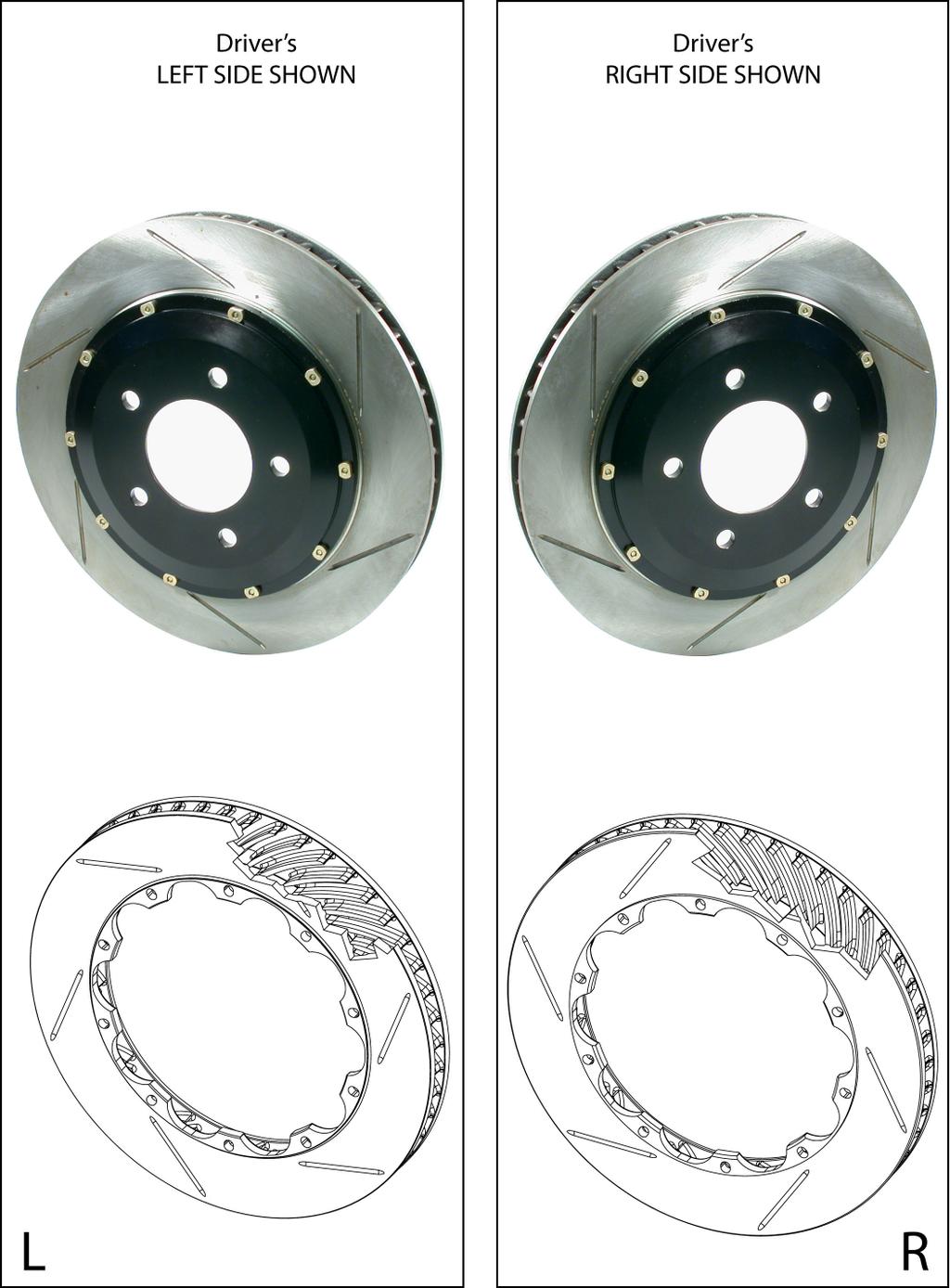
12 Step 6 Install AeroRotor Assembly AeroRotors MUST be cleaned with soap and water prior to installation. Not doing so will damage the rotors and pads, and will prevent the brakes from performing properly. Even though the rotors may look clean, the rust inhibitor is in place, and it must be removed. Not cleaning the rotors will severely impact the performance of your new brake system. Warning: Do not skip this step! Install the hat and rotor assembly, ensuring that the rotor is seated squarely on the hub face. If necessary, clean the face of the hub, using a wire brush or similar means. Secure the stock rotor retaining screws, using a Phillips-head screwdriver. Note: The AeroRotor shown here is not plated, but it gives an accurate representation of the position and orientation of the rotor. Note: Be sure that the rotor assembly is on the correct side of the car, as reversing the rotors will severely decrease the cooling capacity of the system. The rotors are clearly marked L and R with orange tags on the rotor hats. If the tags are not legible, the vanes inside the rotor should lean to the rear of the car on the top side of the rotor (see the following pages for more-detailed images). 12
13 13


14 Caliper Component Identification Use a light film of anti-seize on the bridge bolt shafts and threads The ST-40 original equipment caliper uses a common Porsche-style pad. The Friction Materials Standards Institute (FMSI) number for the pad backing plate is D372. For further pad interchange information, please see the FAQ section of the StopTech website at: 14

15 Step 7 Install Caliper and Pads Note: The images in this section may not be of the vehicle noted, but they give a proper representation of the correct installation. Determine the left- and right-hand side calipers. They are clearly marked on the box, but as a check, the bleed screws are always positioned at the top of the caliper. If installing a four-wheel kit, with ST-40 calipers on the front and rear of the vehicle, be sure that the correct caliper is on each corner. The calipers with the smaller piston sizes go on the rear of the vehicle. Remove the two bolts holding the caliper bridge in place, using a 5mm Allen wrench. Bridge Bolts Remove the caliper bridge, taking note of the direction in which it is installed, and the correct location of the pad-retaining wire clip, which typically, but not always, remains attached to the bridge. In order to stiffen the caliper, the bridge must have a snug fit, and the bolts may be tight when removing them. Keep turning the bolts gently, with pressure applied in the direction of removal. After removing the bolts, it may be necessary to tap the bridge out from the inside of the caliper, using a mallet or similar tool (the handle of a tool works well for this). With use, the bridge and bolts will become easier to remove and insert. 15
16 Step 7 (Cont d.) Install Caliper and Pads Install the caliper onto the adapter bracket, orienting it so that the bleed screws are positioned on the top side of the caliper. Be sure that the caliper is square and evenly started on both studs. It may be necessary to use a mallet to gently tap the caliper into position. Install the Jet nuts onto each stud, with one 12mm washer under each nut. Tighten the Jet nuts to 40 lb-ft of torque, using a 1/2 socket. Slide the brake pads into position within the caliper, taking care to ensure that the friction side of each pad is facing the rotor. (Yes, they have been installed backward before!) 16
17 Step 7 (Cont d.) Install Caliper and Pads Apply a light film of anti-seize compound onto the bridge bolt shafts and threads. Install the bridge by sliding it into position, and rocking it until one of the bolt holes lines up. Take care to ensure that the bridge is slid straight and parallel into the caliper body opening. Note: The bridge is directional, and should be positioned so that the air-scoop opening is located in the top half of the bridge. Insert the first bridge bolt, from the outside of the caliper, and start the first few threads, using a 5mm Allen wrench. Start the second bolt, and apply pressure to the bridge, using the palm of your hand, or by gently tapping the bridge with a mallet, until the bolt engages in the hole. Start the first few threads, using a 5mm Allen wrench. The orientation of the bridge should be as shown in the photograph, with the air-scoop opening located in the top half of the bridge. Torque each bolt to approximately 8-10 lb-ft, using a standard 5mm Allen wrench. Do not use a torque wrench, as the use of anti-seize compound will cause a false reading. Do not over-torque the bridge bolts - snug is tight enough. Warning: Do not hammer the bridge bolts into place. Tap the bridge, not the bolts! 17
18 Step 8 Attach Stainless Steel Brake Line Install the caliper end of the stainless steel brake line by first placing a copper crush washer on either side of the banjo fitting, then inserting the banjo bolt into the caliper. Copper crush washers Banjo bolt Finger-tighten the banjo bolt temporarily, until the line locator bracket is in place. Do not install the brake lines twisted. Each stainless steel front brake line for the Acura TSX is pre-fitted with a new line locator, which replaces the stock line locator. Fit the new line locator onto the wheel strut bracket, and tighten the stock retaining bolt on the line locator, using a 12mm wrench or socket. The orientation of the banjo fitting should be as shown in the photograph, with the brake line pointing toward the line locator. Once the line locator is in place, torque the banjo bolt on the outboard end of the line to approximately 14 lb-ft, using a 12mm wrench or socket. Note: Do not use a torque wrench, as overtightening the bolt can strip the aluminum threads, causing irreparable damage to the caliper. 18

19 Step 8 (Cont d.) Attach Stainless Steel Brake Line Remove the rubber cap from the hard line, and screw the stainless steel brake line onto the hard line fitting by hand for a few turns. Use a 17mm wrench to hold the stainless line inboard fitting, while using a 10 mm flare wrench to tighten the hard line fitting. Reinstall the brake line retaining clip, using a mallet to gently tap it into place. After securing the brake line, turn the wheels lock-to-lock, to ensure that the brake line is not binding in any way, nor interfering with any suspension component, including the CV boot and axle/drive shaft. Adjust the line, if necessary, by loosening the banjo bolt, and realigning the brake line, or by loosening the inboard end of the line, and slightly re-clocking the fitting. Once the line is properly positioned, apply two cable ties to the brake line, one on either side of the line locator, to ensure that the line does not slip. 19
20 Step 9 Bleed Brakes Complete the installation on both sides of the vehicle before bleeding the system. Warning: Double-check that the stainless steel brake lines you ve just installed are not binding in any way, nor interfering with any suspension component, including the CV boot and the axle/drive shaft. Adjust each line, if necessary, by loosening the banjo bolt, and realigning the brake line, or by loosening the inboard end of the line, and slightly re-clocking the fitting. Note: The calipers and lines will need to fill with fluid, quickly draining the master cylinder reservoir. Keep a close watch on the fluid level when initially bleeding the system. Do not allow the master cylinder reservoir to run dry, and to draw in air. Doing so may result in the brake system needing to be serviced by a certified brake technician. Bleed the brake system, using an 11mm box wrench, to loosen the bleed screws. The sequence for bleeding the brakes should be: 1. Right outboard bleed screw 2. Right inboard bleed screw 3. Left outboard bleed screw 4. Left inboard bleed screw Though a torque wrench is not typically used on bleed screws, as a reference, the torque for bleed screws should be approximately lb-inch. After initially bleeding the system, gently tap the caliper body with a mallet to dislodge any small air bubbles, then re-bleed the brakes. After bleeding, apply constant pressure to the brake pedal, and check all connections - including bleed screws, and both ends of the brake line - for leaks. Warning: Brake fluid will damage most painted surfaces. Immediately clean spilled brake fluid from any painted surface, including the caliper. Though caliper paint is designed to resist harsh chemicals, prolonged exposure will damage the finish. 20
21 Step 10 Reinstall Wheels It is very important to check the wheel-to-caliper clearance before installing wheels! Note: Some wheels are balanced on the inside, with adhesive-backed lead weights. If the weight is on the outboard edge, behind the spokes, it may interfere with the caliper. If necessary, note the weight and location of the lead, and place a new piece of the same weight further inboard or outboard, to clear the caliper. If you rotate the tires regularly, check the lead weight positions on all four wheels, and also on the spare, if it is full-sized. Reinstall the wheels, and torque the lug nuts to your wheel manufacturer s specifications. It may be necessary to snug the bolts before lowering the vehicle, and to then torque the wheels when the car is on the ground. Alternatively, an assistant may depress the brake pedal while you tighten the wheel nuts to the proper torque setting. Carefully test-drive the vehicle in a safe area, at low speed, to ensure that all components are working correctly. Then follow the pad and rotor bed-in procedure on the following pages. 21
22 AeroRotor TM Installation & Bed-in Procedure READ THIS NOW FAILURE TO READ, UNDERSTAND AND FOLLOW THESE PROCEDURES WILL CAUSE PERMANENT DAMAGE TO YOUR BRAKE ROTORS, AND WILL KEEP THE SYSTEM FROM WORKING AT ITS FULL CAPACITY. The majority of brake system problems are due to improper installation and/or bed-in of the rotors and pads. By reading and understanding the following, you will avoid the most common causes of poor brake performance and vibration. FAILURE TO READ AND UNDERSTAND THIS MAY CAUSE SERIOUS PERMANENT DAMAGE TO YOUR NEW ROTORS. Wash Non-Plated AeroRotors with SOAP AND WATER before installation. StopTech coats non-plated AeroRotors with a water-soluble, environmentally friendly rust inhibitor that MUST be cleaned off before use. A non-plated rotor looks like bare metal, while plated rotors are bright silver in color, and do not need to be washed. Even though you may not see a change in the rotor color, if the rotor is not rusty, the rust inhibitor is there. Use soap and water, NOT BRAKE CLEANER to wash the rotors. A small piece of Scotchbrite works well for scrubbing. When cleaned and rinsed properly, the surface of the rotor may show a light rust color, which is normal. Bed-in your new pads and rotors by carefully observing the procedure described on this and the following page. Bed-in of rotors and pads is critical to the optimum performance of your new brakes. When beddingin new parts, you are not only heat-cycling the pads, you are also depositing a layer of pad material onto the rotor face. If not bedded-in properly, an uneven layer of pad material will be deposited onto the rotor, causing vibration. Virtually every instance of a warped rotor is attributed to uneven pad deposition. Note: Plated rotors must be driven with gentle braking, until the CAD plating is worn off of the rotor faces, BEFORE starting the bed-in procedure. Do not use brakes aggressively until the plating is worn off, typically after several miles of driving. Typically, a heavy-braking street driver will experience approximately 1 to 1.1G s of deceleration. At this rate, the ABS will be activated on such equipped vehicles. A moderate braking effort is needed to properly bed-in rotors and pads. If ABS intervention or lock-up were represented as 100% brake effort, a stopping force of approximately 70-80%, just short of ABS intervention or lock-up, is a general estimate of the pedal effort you are trying to achieve. (Continued on next page) 22
23 Rotor and Pad Bed-in (Cont d.) Note: Bedding-in of pads should not be done in poor weather conditions, nor on wet roads. After completing the installation, make a series of 10 stops from 60 to 5-10 MPH. At the end of each stop, immediately accelerate to 60 again for the next stop. Run all stops in one cycle. During the 60 to 5-10 MPH cycle of stops, the exact speed is not critical. Accelerate to approximately 60, then begin braking. As you approach 5-10 MPH, it is not necessary to watch the speedometer. Keep your eyes on the road, and approximate your speed at the end of each stop. D O N O T COME TO A COMPLETE STOP, WHILE LEAVING YOUR FOOT ON THE BRAKE PEDAL, AS YOU MAY IM- PRINT PAD MATERIAL ONTO THE ROTOR, CAUSING A VIBRATION. If racing or higher-performance pads are being used, add four stops from 80 to 5-10 MPH, and if full race pads are being used, add four stops from 100 to 5-10 MPH. There are several indicators to look for while bedding-in the system: On the 8th or 9th stop, there should be a distinct smell from the brakes. Smoke may also be evident after several stops. Also on the 8th or 9th stop, some friction material will experience green fade. This is a slight fading of the brakes. The fade will stabilize, but will not completely go away until the brakes have cooled. After the bed-in cycle is finished, there will be a blue tint on the rotor, with a light gray film on the rotor face. The blue tint indicates that the rotor has reached the proper bed-in temperature, and the gray film is pad material starting to transfer onto the rotor face. This is normal! After the first bed-in cycle shown above, the brakes will still not be operating at their best capacity. A second or third bed-in cycle is typically necessary before the brakes really start to come in. A cycle is a series of stops, followed by a cool-down. StopTech does not endorse speeding on public roads. If going above the legal speed limit, do so in a safe area, away from traffic, and at your own risk. After the final stop of each cycle, drive as much as possible without using the brakes, to cool off the system. Ideally, the brakes should be allowed to cool to ambient temperature before using them again. DO NOT COME TO A COMPLETE STOP WHEN THE SYSTEM IS HOT, WHILE LEAVING YOUR FOOT ON THE BRAKE PEDAL. PAD MATERIAL MAY TRANSFER ONTO THE ROTOR, CAUSING A VIBRATION. If you have any questions about rotor and pad bed-in, any aspect of your StopTech brake kit, or brakes in general, please contact the StopTech Customer Service Department at (310) , or us at support@stoptech.com 23
24 Thank you for selecting StopTech. We realize that you had a choice when selecting a big brake upgrade for your vehicle, and we know that you ll be happy with our system. We proudly support our fine products. For any assistance or questions, please contact our Customer Service Department at (310) or us at support@stoptech.com 24
Installation Instructions Porsche C Carrera 2S Cayman S Front Big Brake Upgrade ST-60 Caliper
 Installation Instructions Porsche 1998-2004 996 C2 2005+ 997 Carrera 2S 2006-2010 Cayman S Front Big Brake Upgrade ST-60 Caliper 98-788-1670-00 05/10/10 1 Porsche Front Big Brake Kit Note: It is important
Installation Manual BMW E39 M5 and 5-Series
 Installation Manual 2000+ BMW E39 M5 and 5-Series Rear Big Brake Upgrade ST-40 Caliper 98-135-1471-04 11/18/09 COMPONENT IDENTIFICATION AeroRotor and Hat Assemblies Caliper Brackets High-Performance Street
Installation Instructions. Acura TSX mm Rear Big Brake Upgrade ST-22/ST-10 Calipers
 Installation Instructions Acura TSX 2004+ 328mm Rear Big Brake Upgrade ST-22/ST-10 Calipers 98-059-1331-03 02-22-05 Acura TSX Rear Big Brake Kit Your StopTech Big Brake kit includes the following: ST-22
/14/09. Mitsubishi EVO X. 355mm Front Big Brake Upgrade ST-60 Caliper
 98.625.1670-01 12/14/09 Mitsubishi EVO X 355mm Front Big Brake Upgrade ST-60 Caliper COMPONENT IDENTIFICATION AeroRotor and Hat Assemblies ST-60 Caliper ST-60 Caliper High-Performance Street Pads Caliper
Installation Instructions. Audi S5, A5, A4 332, 355 & 380mm Front Big Brake Upgrade ST-40 and ST-60 Caliper
 Installation Instructions Audi S5, A5, A4 332, 355 & 380mm Front Big Brake Upgrade ST-40 and ST-60 Caliper 98.114.1680.02 07/23/09 Audi S5, A5, A4 Big Brake Kit Kit Contents Your StopTech Big Brake kit
Infiniti G35 Sport Sedan 2007+
 ion s Infiniti G35 Sport Sedan 2007+ 355mm Front Big Brake Upgrade ST-40 Caliper 98.487.1450.01 12/10/09 Infiniti G35 Front Big Brake Kit (This is a representative photograph. The actual components in
Installation Instructions Subaru Impreza WRX 2002+
 Installation Instructions Subaru Impreza WRX 2002+ 328mm Rear Big Brake Upgrade ST-22 Caliper 98-836-1331-03 01/04/10 Subaru Impreza WRX Rear Big Brake Kit (This is a representative photograph. The actual
/17/09
 98.180.1670.04 11/17/09 COMPONENT IDENTIFICATION AeroRotor and Hat Assemblies ST-60 Caliper ST-60 Caliper High-Performance Street Pads Caliper Brackets Stainless Braided Lines and Hardware Big Brake Kit
Installation Instructions
 Installation Instructions Subaru Impreza WRX STI 2002-2006 STR-40 Rear Trophy Kit 98-838-1431-00 03/26/09 cl. APPLICATION DISCLAIMER Caliper Clearance Most 17 wheels will clear the outer diameter of the
Installation Instructions BMW E92 M3
 Installation Instructions BMW E92 M3 355mm Rear Big Brake Upgrade ST-40 Caliper 98.160.1471-01 11/17/09 BMW E92 M3 Big Brake Kit Kit Contents Your StopTech Big Brake kit includes the following: 1 pair
Installation Instructions For GM SUVs & Trucks
 Installation Instructions For GM SUVs & Trucks 380mm (15 ) Front Big Brake Upgrade 98-182-1480-02 11/17/09 1 pair of ST-45, 4 Piston Calipers sized specifically for GM SUV s & Trucks 1 set of high performance
Installation Instructions VW Corrado VR Golf GTi VR Jetta VR Passat VR6 Later Model VWs
 Installation Instructions Installation Instructions For 1992-95 VW Corrado VR6 1994-95 Golf GTi VR6 1994+ Jetta VR6 1993-97 Passat VR6 Later Model VWs Front Big Brake Upgrade 98-887-1430-03 01/04/10 VW
Installation Instructions
 Installation Instructions 98-836-1430-11 01/04/10 Subaru Impreza WRX / STi Front Big Brake Upgrade 328, 332, 355mm Rotors ST40 Front Big Brake Kit for the Subaru WRX / STi Kit Contents (This is a representative
Mazda RX MX-5 Miata Front Big Brake Upgrade ST-40 Caliper / 2-piece Rotor
 Mazda RX-8 2004+ MX-5 Miata 2006+ Front Big Brake Upgrade ST-40 Caliper / 2-piece Rotor 98-548-1430-00 3/14/16 Front Axle Kit Note: It is important to read and understand this ENTIRE installation manual,
Installation Instructions Audi S
 Installation Instructions Audi S4 1999-2002 ST-22 Rear 328mm Big Brake Upgrade 98-130-1331 Rev. A 08-06-05 COMPONENT IDENTIFICATION TION AeroRotor and Hat Assemblies Caliper Brackets High-Performance Street
BMW 135i and 335i Rear Big Brake Upgrade ST-40 Caliper F1.00 1/15/10
 BMW 135i and 335i 2007+ Rear Big Brake Upgrade ST-40 Caliper 98.165.14F1.00 1/15/10 APPLICATION DISCLAIMER Caliper Clearance Most 17 wheels will clear the outer diameter of the caliper for a 328mm or 332mm
Installation Instructions For Toyota Tundra & Sequoia. 332 & 355mm
 Installation Instructions For Toyota Tundra & Sequoia 332 & 355mm Front Big Brake Upgrade Document: 98-856-1460 Rev. B 01-09-03 COMPONENT IDENTIFICATION AeroRotors with Aluminum Hats ST-40 Calipers Jet
Installation Instructions for the Nissan 300 ZX
 Installation Instructions for the Nissan 300 ZX 1990-1996 Front Big Brake Upgrade 98-647-1450 Rev. A 09-30-02 COMPONENT IDENTIFICATION TION 332mm AeroRotor and Hat Assemblies Caliper Brackets High Performance
SCION tc BIG BRAKE KIT Section I - Installation Preparation
 SCION tc 2005- BIG BRAKE KIT Section I - Installation Preparation Part Number: PTR09-21080 Kit Contents Item # Quantity Reqd. Description 1 1 Brake Rotor, LH Front 2 1 Brake Rotor, RH Front 3 1 Brake Caliper
LEXUS IS 250 Front Performance Brake Kit Section I - Installation Preparation
 LEXUS IS 250 Front 2006- Performance Brake Kit Section I - Installation Preparation Part Number: PTR09-53080 Kit Contents Item # Quantity Reqd. Description 1 1 Brake Rotor, LH Front 2 1 Brake Rotor, RH
INSTALLATION INSTRUCTIONS
 INSTALLATION INSTRUCTIONS REAR DISC CONVERSION KIT A126-2 1988-98 C1500 2WD 10" REAR DRUM Thank you for choosing STAINLESS STEEL BRAKES CORPORATION for your braking needs. Pleases take the time to read
INSTALLATION INSTRUCTIONS
 INSTALLATION INSTRUCTIONS REAR DISC BRAKE CONVERSION KIT A126-1 1973-87 CHEVROLET 1/2 TON 2WD Thank you for choosing STAINLESS STEEL BRAKES CORPORATION for your braking needs. Pleases take the time to
TOYOTA TUNDRA BIG BRAKE KIT Section I - Installation Preparation
 TOYOTA TUNDRA 2007- BIG BRAKE KIT Section I - Installation Preparation Part Number: PTR09-34070 Kit Contents Item # Quantity Reqd. Description 1 1 Brake Rotor, LH Front 2 1 Brake Rotor, RH Front 3 1 Brake
LEXUS IS 250/ PERFORMANCE GS BRAKE KIT IS 250/350 Conv (FRONT) IS 250/350 Conv (REAR) Preparation
 IS 250/350 Conv (REAR) Preparation") Preparation Part Number: PTR09-53108: All IS 250 Models - Front PTR09-30102: IS 350 & GS 350 - Front PTR09-53109: IS 250 AWD & RWD - Rear PTR09-53110: All IS 350 Models - Rear PTR09-53103: IS 250 C & GS
Preparation Part Number: PTR09-53108: All IS 250 Models - Front PTR09-30102: IS 350 & GS 350 - Front PTR09-53109: IS 250 AWD & RWD - Rear PTR09-53110: All IS 350 Models - Rear PTR09-53103: IS 250 C & GS
IRS Racing Brake Kit (MMBAK-15, -16)
") 3430 Sacramento Dr., Unit D San Luis Obispo, CA 93401 Telephone: 805/544-8748 Fax: 805/544-8645 www.maximummotorsports.com IRS Racing Brake Kit (MMBAK-15, -16) Floating rotors (MMBAK-16 ONLY) can move
3430 Sacramento Dr., Unit D San Luis Obispo, CA 93401 Telephone: 805/544-8748 Fax: 805/544-8645 www.maximummotorsports.com IRS Racing Brake Kit (MMBAK-15, -16) Floating rotors (MMBAK-16 ONLY) can move
INSTALLATION INSTRUCTIONS
 INSTALLATION INSTRUCTIONS REAR DISC CONVERSION KIT A128-4 1997-2004 JEEP WRANGLER (TJ) WITH DANA 44 AXLES (non-abs) Thank you for choosing STAINLESS STEEL BRAKES for your braking needs. Pleases take the
INSTALLATION INSTRUCTIONS
 INSTALLATION INSTRUCTIONS REAR DISC BRAKE CONVERSION KIT A126-3 1988-98 CHEVY K1500 4WD 10" DRUMS Thank you for choosing STAINLESS STEEL BRAKES CORPORATION for your braking needs. Pleases take the time
Endurance Competition Brake System Installation Guide: 2014 Chevrolet Corvette C7
 Endurance Competition Brake System Installation Guide: 2014 Chevrolet Corvette C7 Version 1.0 Warning: Essex Competition kits are for off-road use only. The components in these systems are not designed
Competition Brake System Installation Guide: Subaru WRX
 Competition Brake System Installation Guide: 2015+ Subaru WRX Version 1.0 Warning: Essex Competition kits are for off-road use only. The components in these systems are not designed for use on public roads.
STāSIS Engineering R8 Brake System
 STāSIS Engineering R8 Brake System Brake Kit Installation Instruction Application Guide SE811-B30-91-00 R8 Brake System Special Tools Required Qty Description 1 10 MM Allen Head Socket 1 M10 Triple Square
DISC BRAKE/DUAL MASTER CYLINDER CONVERSION. Tools, Equipment and Supplies Needed:
 Please take the time to read the enclosed instructions carefully. If you have any questions, call our Product Assistance personnel for clarification. It is important to note that these instructions contain
INSTALLATION INSTRUCTIONS
 INSTALLATION INSTRUCTIONS REAR DISC BRAKE CONVERSION KIT A158 1994-97 Dodge Ram 1500 (2WD & 4WD) and REAR DISC BRAKE CONVERSION KIT A158-1 1998-01 Dodge Ram 1500 (2WD & 4WD) Thank you for choosing STAINLESS
Installation Instructions
 Preparing your vehicle to install your brake system upgrade 1. Rack the vehicle. 2. If you don t have a rack, then you must take extra safety precautions. 3. Choose a firmly packed and level ground to
ASSEMBLY INSTRUCTIONS FOR PART NUMBER GROUP
 ASSEMBLY INSTRUCTIONS FOR DYNAPRO 6 BIG BRAKE FRONT HAT KIT, 1.19 DIAMETER VENTED ROTOR 1990-005 ACURA/CIVIC ( LUG) 000-003 CIVIC SI ( LUG) 007 - PRESENT HONDA FIT FOR FACTORY 6 mm DISC SPINDLE PART NUMBER
INSTALLATION INSTRUCTIONS
 INSTALLATION INSTRUCTIONS REAR DISC BRAKE CONVERSION KIT A125-3 1965-72 GM A-BODY 10 & 12 BOLT AXLES Thank you for choosing STAINLESS STEEL BRAKES CORPORATION for your braking needs. Pleases take the time
Radi-Cal Competition Brake System Installation Guide: Subaru Sti
 Radi-Cal Competition Brake System Installation Guide: 2004+ Subaru Sti 13.99.00052 Version 1.0 Warning: Essex Competition kits are for off-road use only. The components in these systems are not designed
Installation Instructions
 Installation Instructions Rear Disc Brake Conversion Kit Item # RC4001, RC4001X Applications: Mopar 7.25, 8.25, 9.25 Axles Thank you for choosing Leed Brakes for your automotive product needs. Before you
Installation Instructions
 Installation Instructions Rear Disc Brake Conversion Kit Item # RC1001, RC1001X Applications: 64-72 A-body, 67 F-Body, 63-67 X-body with Non Staggered Shocks Thank you for choosing GPS Auto for your automotive
STaSIS Engineering MkV Mono4 Front Brakes
 STaSIS Engineering MkV Mono4 Front Brakes 370mm Brake Kit KB04.1002 Parts List: Qty Description Part Number 1 Rotor Alcon 370x28 RH BR01.1020.00 1 Rotor Alcon 370x28 LH BR01.1021.00 2 MkV 370 Brake Hat
370 and 390 Mono 6 Brake Kit Installation Guide
 370 and 390 Mono 6 Brake Kit Installation Guide Application Guide Description C7 A6 / A7 390mm Mono6 Brake Kit B8 A4/S4/A5/S5/Q5 390mm Mono 6 Brake Kit C7 A6 / A7 370mm Mono 6 Brake Kit B8 A4/S4/A5/S5/Q5
INSTALLATION INSTRUCTIONS
 INSTALLATION INSTRUCTIONS REAR DISC CONVERSION KIT A136-1 1976-86 AMC 20 AXLES WITH WARN FULL FLOATING AXLE CONVERSION Thank you for choosing STAINLESS STEEL BRAKES CORPORATION for your braking needs.
ASSEMBLY INSTRUCTIONS
 ASSEMBLY INSTRUCTIONS FOR FORGED SUPERLITE BIG BRAKE FRONT HUB KIT WITH 3.00 DIAMETER VENTED ROTOR 968-969 FORD MUSTANG (DISC BRAKE SPINDLE ONLY) PART NUMBER GROUP 0-950 WARNING INSTALLATION OF THIS KIT
INSTALLATION INSTRUCTIONS
 INSTALLATION INSTRUCTIONS REAR DISC BRAKE CONVERSION KIT A157 1991-2004 Dodge Dakota 2WD 1991-2002 Dodge Dakota 4WD 1998-2002 Dodge Durango Thank you for choosing STAINLESS STEEL BRAKES CORPORATION for
Rear Competition Brake System Installation Guide: Mustang rear competition system
 Rear Competition Brake System Installation Guide: 2015+ Mustang rear competition system 13.99.00035 Version 1.0 Warning: Essex Competition kits are for off-road use only. The components in these systems
ASSEMBLY INSTRUCTIONS FOR DYNAPRO BIG BRAKE FRONT HAT KIT, WITH DIAMETER VENTED ROTOR - RACE
 www.wilwood.com ASSEMBLY INSTRUCTIONS FOR DYNAPRO BIG BRAKE FRONT HAT KIT, WITH 11.75 DIAMETER VENTED ROTOR - RACE 00 - PRESENT BMW MINI COOPER AND MINI COOPER S PART NUMBER GROUP 10-870 DISC BRAKES SHOULD
Competition Brake System Installation Guide: Front BMW E46 M
 Competition Brake System Installation Guide: Front BMW E46 M3 2001-2006 Version 1.2 WARNING: Essex Competition Brake Systems are for off-road use only. The components in these systems were not designed
INSTALLATION INSTRUCTIONS
 INSTALLATION INSTRUCTIONS REAR DISC BRAKE CONVERSION KIT A125-2 1955-70 FULL SIZE CHEVROLET Thank you for choosing STAINLESS STEEL BRAKES CORPORATION for your braking needs. Pleases take the time to read
INSTALLATION INSTRUCTIONS
 INSTALLATION INSTRUCTIONS REAR DISC CONVERSION KIT A128 1990-1995 JEEP WRANGLER (YJ) WITH DANA 35 AXLES (non-abs) Thank you for choosing STAINLESS STEEL BRAKES CORPORATION for your braking needs. Pleases
Competition Brake System Installation Guide: BMW M3 (E46) 6-Piston Front
 6-Piston Front") Competition Brake System Installation Guide: BMW M3 (E46) 6-Piston Front Version 1.0 Warning: Essex Competition kits are for off-road use only. The components in these systems are not designed for use
Competition Brake System Installation Guide: BMW M3 (E46) 6-Piston Front Version 1.0 Warning: Essex Competition kits are for off-road use only. The components in these systems are not designed for use
INSTALLATION INSTRUCTIONS
 INSTALLATION INSTRUCTIONS PERFORMANCE AT THE WHEELS KIT W155-5 CHRYSLER 8 3 /4" & 9 3 /4" REAR AXLES Thank you for choosing STAINLESS STEEL BRAKES CORPORATION for your braking needs. Please take the time
ASSEMBLY INSTRUCTIONS FOR DYNALITE DRAG RACE FRONT HUB KIT WITH DIAMETER SOLID ROTOR PINTO / MUSTANG II
 ASSEMBLY INSTRUCTIONS FOR DYNALITE DRAG RACE FRONT HUB KIT WITH 0.75 DIAMETER SOLID ROTOR 97-978 PINTO / MUSTANG II (FIVE LUG CONFIGURATION ONLY)* PART NUMBER GROUP 0-03-B DISC BRAKES SHOULD ONLY BE INSTALLED
INSTALLATION INSTRUCTIONS PERFORMANCE AT THE WHEELS KIT W125
 INSTALLATION INSTRUCTIONS PERFORMANCE AT THE WHEELS KIT W125 1968-81 CAMARO & FIREBIRD 10 & 12 BOLT W/"C" CLIPS Thank you for choosing STAINLESS STEEL BRAKES CORPORATION for your braking needs. Pleases
Installation Instructions
 Installation Instructions Rear Disc Brake Conversion Kit Item # RC2001, RC2001X Applications: Mopar 8-3/4 & 9-3/4 Rear Axles Thank you for choosing Leed Brakes for your automotive product needs. Before
INSTALLATION INSTRUCTIONS
 INSTALLATION INSTRUCTIONS DISC BRAKE CONVERSION KITS A120-4 & A120-5 1964-1/2-66 Ford & Mercury Thank you for choosing STAINLESS STEEL BRAKES CORPORATION for your braking needs. Pleases take the time to
Tools, Equipment and Supplies Needed:
 153-162 DISC BRAKE/DUAL MASTER CYLINDER CONVERSION Please take the time to read the enclosed instructions carefully. If you have any questions, call our Product Assistance personnel for clarifi cation.
Radi-Cal Competition Brake System Installation Guide: Audi TT-RS
 Radi-Cal Competition Brake System Installation Guide: Audi TT-RS 13.99.00060 Version 1.0 Warning: Essex Competition kits are for off-road use only. The components in these systems are not designed for
BIG BRAKE KIT FOR TJ, ZJ, XJ D44 & D30
 BIG BRAKE KIT FOR TJ, ZJ, XJ D44 & D30 16 KIT PART NUMBER 41002010AA 17 KIT PART NUMBER 41002015AA Installation Guide (Updated 12/01/09) Page 1 of 11 PLEASE READ BEFORE YOU START IN ORDER TO INSTALL THIS
INSTALLATION INSTRUCTIONS
 INSTALLATION INSTRUCTIONS INSTALLATION INSTRUCTIONS FOR A136 REAR DRUM TO DISC BRAKE CONVERSION KIT for 1970-75 Jeep, CJ SERIES with Dana 44 flanged axle Thank you for choosing STAINLESS STEEL BRAKES CORPORATION
INSTALLATION INSTRUCTIONS
 INSTALLATION INSTRUCTIONS FORCE 10 SPORT R1 REAR DISC CONVERSION KIT A126-50 2005-10 Chevrolet Silverado and GMC Sierra Thank you for choosing STAINLESS STEEL BRAKES CORPORATION for your braking needs.
INSTALLATION INSTRUCTIONS
 INSTALLATION INSTRUCTIONS REAR CONVERSION KIT A111-2 (FORD 8" & 9" SMALL BEARING) & REAR CONVERSION KIT A111-3 (FORD 9 TORINO) Thank you for choosing STAINLESS STEEL BRAKES CORPORATION for your braking
INSTALLATION INSTRUCTIONS
 INSTALLATION INSTRUCTIONS PERFORMANCE AT THE WHEELS KIT W125-42 GM 10 & 12 Bolt Rear Axles with Staggered or non-staggered Shocks with C-Clips Thank you for choosing STAINLESS STEEL BRAKES CORPORATION
APR BBK Installation Instructions
 APR BBK Installation Instructions TL100111 Before starting: Ensure your wheels will clear the calipers in your big brake kit. If you are not sure, please contact support at 800 680 7921 to request a copy
INSTALLATION INSTRUCTIONS
 INSTALLATION INSTRUCTIONS DISC BRAKE CONVERSION KITS A121-1, A121-2, A121-3, A121-4 1967-69 Ford & Mercury Thank you for choosing STAINLESS STEEL BRAKES CORPORATION for your braking needs. Pleases take
INSTALLATION INSTRUCTIONS
 INSTALLATION INSTRUCTIONS REAR DRUM TO DISC BRAKE CONVERSION KIT A130 JEEP CJ SERIES W/AMC-20 REAR AXLES AND 5 x 5-1/2" BOLT CIRCLE Thank you for choosing STAINLESS STEEL BRAKES CORPORATION for your braking
Rear Radi-CAL Competition Brake System Installation Guide: Mazda Miata (ND)
") Rear Radi-CAL Competition Brake System Installation Guide: 2016+ Mazda Miata (ND) 13.99.00053 Version 1.0 Warning: Essex Competition kits are for off-road use only. The components in these systems are
Rear Radi-CAL Competition Brake System Installation Guide: 2016+ Mazda Miata (ND) 13.99.00053 Version 1.0 Warning: Essex Competition kits are for off-road use only. The components in these systems are
Radi-CAL Brake System Installation Guide: Ford Mustang (S197)
") Radi-CAL Brake System Installation Guide: 2006-2013 Ford Mustang (S197) Version 1.0 Warning: Essex Competition kits are for off-road use only. The components in these systems are not designed for use on
Radi-CAL Brake System Installation Guide: 2006-2013 Ford Mustang (S197) Version 1.0 Warning: Essex Competition kits are for off-road use only. The components in these systems are not designed for use on
INSTALLATION INSTRUCTIONS
 INSTALLATION INSTRUCTIONS REAR DISC BRAKE CONVERSION KITS A112, A112-1 & A112-93 1979-93 FORD MUSTANG with 7.5" & 8.8" AXLES Thank you for choosing STAINLESS STEEL BRAKES CORPORATION for your braking needs.
INSTALLATION INSTRUCTIONS
 INSTALLATION INSTRUCTIONS COMP. R AND COMP. S QUICK CHANGE KITS A200, A200-1 Thank you for choosing STAINLESS STEEL BRAKES CORPORATION for your braking needs. Pleases take the time to read and carefully
ASSEMBLY INSTRUCTIONS FOR PRO-MATRIX OE UPGRADE PAD AND ROTOR KIT REAR, WITH DIAMETER VENTED ROTOR CHEVROLET C-4 CORVETTE
 ASSEMBLY INSTRUCTIONS FOR PRO-MATRIX OE UPGRADE PAD AND ROTOR KIT REAR, WITH 1.00 DIAMETER VENTED ROTOR 1988-1996 CHEVROLET C-4 CORVETTE PART NUMBER GROUP 140-8314 DISC BRAKES SHOULD ONLY BE INSTALLED
Installation Guide: Front Brake Pad
 Installation Guide: Front Brake Pad Ninety percent of the brake pad changes you make during the life of your vehicle will be to the front brakes because they do 60% to 70% of the braking. On most cars,
ASSEMBLY INSTRUCTIONS FOR SUPERLITE 6R PRO SERIES FRONT HUB KIT WITH DIAMETER VENTED ROTOR GENERAL MOTORS G BODY DISC SPINDLE
 ASSEMBLY INSTRUCTIONS FOR SUPERLITE 6R PRO SERIES FRONT HUB KIT WITH 1.88 DIAMETER VENTED ROTOR 1980-1987 GENERAL MOTORS G BODY DISC SPINDLE PART NUMBER GROUP 10-198 DISC BRAKES SHOULD ONLY BE INSTALLED
INSTALLATION INSTRUCTIONS
 INSTALLATION INSTRUCTIONS REAR DISC BRAKE CONVERSION KIT A117-1, A117-2 1991-97 S10 PICKUP & BLAZER 1985-02 ASTRO AND SAFARI VAN Thank you for choosing STAINLESS STEEL BRAKES CORPORATION for your braking
INSTALLATION INSTRUCTIONS
 INSTALLATION INSTRUCTIONS FX4 ELITE REAR DISC CONVERSION KITS WITH INTERNAL PARKING BRAKE A110-14, A111-25, A111-29 for FORD 8" & 9" REAR ENDS Thank you for choosing STAINLESS STEEL BRAKES CORPORATION
INSTALLATION INSTRUCTIONS
 INSTALLATION INSTRUCTIONS REAR DRUM TO DISC BRAKE CONVERSION KIT A118 pre-1985 Ford F150 (except 1983-1984 w/super H/D axle) Thank you for choosing STAINLESS STEEL BRAKES CORPORATION for your braking needs.
INSTALLATION INSTRUCTIONS
 INSTALLATION INSTRUCTIONS POWER FRONT DISC CONVERSION KIT A126-7 1963-66 CHEVY C10 PICKUP NON-POWER FRONT DISC CONVERSION KIT A126-8 1963-72 CHEVY C10 PICKUP Thank you for choosing STAINLESS STEEL BRAKES
ASSEMBLY INSTRUCTIONS
 ASSEMBLY INSTRUCTIONS FOR DYNALITE PRO SERIES FRONT HUB KIT WITH.75 DIAMETER VENTED ROTOR 970-973 FORD MUSTANG (DRUM / DISC SPINDLE) PART NUMBER GROUP 0-905 WARNING INSTALLATION OF THIS KIT SHOULD ONLY
ASSEMBLY INSTRUCTIONS
 ASSEMBLY INSTRUCTIONS FOR DYNALITE PRO SERIES FRONT HUB KIT WITH.75 DIAMETER VENTED ROTOR 1980-1987 GENERAL MOTORS G BODY DISC SPINDLE PART NUMBER GROUP -508-B WARNING INSTALLATION OF THIS KIT SHOULD ONLY
INSTALLATION INSTRUCTIONS
 INSTALLATION INSTRUCTIONS R1 REAR DRUM TO DISC BRAKE CONVERSION KIT A130-3 JEEP CJ SERIES W/AMC-20 REAR AXLES AND 5 x 5-1/2" BOLT CIRCLE Thank you for choosing STAINLESS STEEL BRAKES CORPORATION for your
INSTALLATION INSTRUCTIONS
 INSTALLATION INSTRUCTIONS FRONT BIG BRAKE CONVERSION KIT A112-5 1987-93 FORD MUSTANG Thank you for choosing STAINLESS STEEL BRAKES CORPORATION for your braking needs. Pleases take the time to read and
ASSEMBLY INSTRUCTIONS
 ASSEMBLY INSTRUCTIONS FOR DYNALITE PRO SERIES REAR PARKING BRAKE KIT WITH.9 DIAMETER VENTED ROTOR (. OFFSET) 005 - PRESENT MUSTANG 8.8 (5 LUG) PART NUMBER GROUP 0-98 INSTALLATION OF THIS KIT SHOULD ONLY
ASSEMBLY INSTRUCTIONS
 ASSEMBLY INSTRUCTIONS FOR DYNALITE PRO SERIES REAR PARKING BRAKE KIT VENTED ROTOR TYPE (.8 OFFSET) BOLT CHEVY PART NUMBER GROUP 0-7 INSTALLATION OF THIS KIT SHOULD ONLY BE PERFORMED BY PERSONS EXPERIENCED
If you have any difficulties at all, please give us a call. Thank you and enjoy your MetalCloak Products!
 PRODUCT: TJ/LJ 3.5 Dual Rate Lift RockSport Edition READ INSTRUCTIONS IN FULL BEFORE INSTALLATION. QUESTIONS? CALL 916-631-8071 M-F 7:00 AM 5:00 PM PST The MetalCloak experience includes the ease of installation
ASSEMBLY INSTRUCTIONS
 ASSEMBLY INSTRUCTIONS FOR SUPERLITE 6 BIG BRAKE FRONT HAT KIT PRO STREET APPLICATION,.90 DIAMETER VENTED ROTOR 99-00 MUSTANG (5 LUG, STOCK OFFSET) PART NUMBER GROUP 0-907 INSTALLATION OF THIS KIT SHOULD
INSTALLATION INSTRUCTION 88581
 INSTALLATION INSTRUCTION 88581 FOR RANCHO SUSPENSION SYSTEM RS6581B: DODGE RAM READ ALL INSTRUCTIONS THOROUGHLY FROM START TO FINISH BEFORE BEGINNING INSTALLATION Rev C IMPORTANT NOTES! WARNING: This suspension
INSTALLATION INSTRUCTION 88094
 INSTALLATION INSTRUCTION 88094 FOR RANCHO SUSPENSION SYSTEM RS6594B 4WD & 2WD NISSAN TITAN READ ALL INSTRUCTIONS THOROUGHLY FROM START TO FINISH BEFORE BEGINNING INSTALLATION Rev D IMPORTANT NOTES! WARNING:
ASSEMBLY INSTRUCTIONS FOR WILWOOD FRONT D8-6 CALIPER, BRAKE PAD, AND FLEX LINE REPLACEMENT KIT CHEVROLET CORVETTE
 ASSEMBLY INSTRUCTIONS FOR WILWOOD FRONT D8-6 CALIPER, BRAKE PAD, AND FLEX LINE REPLACEMENT KIT 965-98 CHEVROLET CORVETTE PART NUMBER GROUP 40-857 DISC BRAKES SHOULD ONLY BE INSTALLED BY SOMEONE EXPERIENCED
ASSEMBLY INSTRUCTIONS
 ASSEMBLY INSTRUCTIONS FOR DYNALITE PRO SERIES REAR PARKING BRAKE KIT WITH.9 DIAMETER VENTED ROTOR (.36 OFFSET) BIG BEARING FORD PART NUMBER GROUP 0-739 INSTALLATION OF THIS KIT SHOULD ONLY BE PERFORMED
GM FULL SIZE REAR DISC BRAKE KIT
 GM FULL SIZE REAR DISC BRAKE KIT This kit is for axles with a 3 3/8 spread center to center on the top two bolt holes (pictured left). If your axle flange measures 3 1/8 from center to center, you need
EGR Performance Brakes Assembly Instructions DODGE DANA 70 '87 - '93 (Will not fit stock sized dual rear wheels)
") EGR Performance Brakes Assembly Instructions DODGE DANA 70 '87 - '93 (Will not fit stock sized dual rear wheels) Got Brakes? Parts List (2) Vented Rotors (2) Multi hole Cable Mount & L Brkt (2) Axle Tube
EGR Performance Brakes Assembly Instructions DODGE DANA 70 '87 - '93 (Will not fit stock sized dual rear wheels) Got Brakes? Parts List (2) Vented Rotors (2) Multi hole Cable Mount & L Brkt (2) Axle Tube
INSTALLATION INSTRUCTIONS
 INSTALLATION INSTRUCTIONS BIG ROTOR / CALIPER RELOCATION FRONT KITS SUM-BK1422, BK1423, BK1424 1999-2006 GM 1/2 Ton Trucks & SUVs Thank you for choosing SUMMIT RACING for your braking needs. Pleases take
4- Piston Caliper Big Brake Kit Installation Instructions
 4- Piston Caliper Big Brake Kit Installation Instructions For: Austin - Healey BJ8 from (c)26705-on PART # 586-725 440 Rutherford St. Goleta, CA 93117 1-800-667-7872 FAX 805-692-2525 www.mossmotors.com
ASSEMBLY INSTRUCTIONS FOR SUPERLITE 6 BIG BRAKE FRONT CHALLENGE SERIES BRAKE KIT WITH HUB AND DIAMETER VENTED ROTOR
 ASSEMBLY INSTRUCTIONS FOR SUPERLITE BIG BRAKE FRONT CHALLENGE SERIES BRAKE KIT WITH HUB AND 1.88 DIAMETER VENTED ROTOR 197-199 CAMARO, DISC/DRUM SPINDLE 197-1974 NOVA, DISC/DRUM SPINDLE 194-19 CHEVY II,
ASSEMBLY INSTRUCTIONS FOR WILWOOD FRONT D52 CALIPER KIT GM VEHICLES USING D52 CALIPER AND BRAKE PADS WITH 1.
 ASSEMBLY INSTRUCTIONS FOR WILWOOD FRONT D5 CALIPER KIT 1968-1996 GM VEHICLES USING D5 CALIPER AND BRAKE PADS WITH 1.8 THICK ROTORS PART NUMBER GROUP 10-1190 DISC BRAKES SHOULD ONLY BE INSTALLED BY SOMEONE
Copyright 1998 Inter-Industry Conference On Auto Collision Repair v.4.0
 Uniform Procedures For Collision Repair BR11 Brakes 1. Description This procedure describes repair, replacement, and inspection requirements for collisiondamaged brake systems. 2. Purpose The purpose of
INSTALLATION INSTRUCTIONS R1 REAR CONVERSION KIT
 INSTALLATION INSTRUCTIONS R1 REAR CONVERSION KIT INSTRUCTION FOR ASSEMBLY OF JEEP CJ SERIES W/AMC 20 REAR AXLES, 5 x 5-1/2" BOLT CIRCLE WITH A130-4 FULL FLOATING AXLE OR A130-5 (1 PIECE AXLE) Thank you
INSTALLATION INSTRUCTIONS
 INSTALLATION INSTRUCTIONS BIG ROTOR / CALIPER RELOCATION REAR KIT SUM-BK1423 1999-2009 GM 1/2 Ton Trucks & SUVs Thank you for choosing SUMMIT RACING for your braking needs. Pleases take the time to read
INSTALLATION INSTRUCTION 89400
 INSTALLATION INSTRUCTION 89400 FOR RANCHO SUSPENSION SYSTEM RS66400B: 2012 RAM 1500 4WD. READ ALL INSTRUCTIONS THOROUGHLY FROM START TO FINISH BEFORE BEGINNING INSTALLATION Rev B IMPORTANT NOTES! WARNING:
Tundra Racing LOWERING KIT INSTALLATION MANUAL Toyota Tundra 2wd & 4x4 Part #TR-2040 & TR-2050 Reg Cab, Double Cab & Crewmax
 Page 12 Front Coil Spring Perch, Sleeve and Bump Stops Leaf Spring Shackle and Hardware PARTS INCLUDED IN KIT Tundra Racing LOWERING KIT INSTALLATION MANUAL Axle Perches Top & Bottom Plates U-Bolts and
ASSEMBLY INSTRUCTIONS FOR DYNALITE PRO SERIES FRONT HUB KIT WITH DIAMETER VENTED ROTOR EARLY FORD - DRUM SPINDLE
 ASSEMBLY INSTRUCTIONS FOR DYNALITE PRO SERIES FRONT HUB KIT WITH.00 DIAMETER VENTED ROTOR 93-98 EARLY FORD - DRUM SPINDLE PART NUMBER GROUP -3 DISC BRAKES SHOULD ONLY BE INSTALLED BY SOMEONE EXPERIENCED
INSTALLATION INSTRUCTIONS
 INSTALLATION INSTRUCTIONS INSTRUCTION FOR ASSEMBLY OF JEEP CJ SERIES W/AMC 20 REAR AXLES, 5 x 5-1/2" BOLT CIRCLE WITH A130-1 FULL FLOATING AXLE OR A130-2 (1 PIECE AXLE) Thank you for choosing STAINLESS