Department of Electrical Power Engineering and Mechatronics
|
|
|
- Erika Hardy
- 6 years ago
- Views:
Transcription
1 Department of Electrical Power Engineering and Mechatronics MODERNIZATION AND DESIGN OF BALL BEARINGS APPARATUS Veerelaagrite katseseadme konstrueerimine ja moderniseerimine MASTER THESIS Student: Student code: Supervisor: Anilkumar Nagavelli A Leo Teder Tallinn, 2017
2 AUTHOR'S DECLARATION Hereby I declare, that I have written this thesis independently. No academic degree has been applied for based on this material. All works, major viewpoints and data of the other authors used in this thesis have been referenced Author:... /signature / Thesis is in accordance with terms and requirements Supervisor:... /signature/ Accepted for defense Chairman of theses defence commission:... /name and signature/
3 TUT Department of Mechatronics MASTERS THESIS SHEET OF TASKS Year: 2017 semester: V th Student: Curricular: specialty: Supervisor: Advisor: Anilkumar Nagavelli (A146461) Mechatronics Mechatronics Leo Teder (Teaching assistant) Priit Põdra (Associate Professor) MASTERS THESIS TOPIC: (In English): Modernization and Design of Ball Bearing Apparatus. (In Estonian): Veerelaagrite katseseadme konstrueerimine ja moderniseerimine. Assignments to be completed and the schedule for their completion: No. Description of the Tasks Timetable 1. Device structural scheme and functional specification. 2 Weeks 2. Design of device transmission and Loading system. 2 weeks 3. Design of the device friction moment measuring system. 2 weeks 4. Design of device control system. 2 weeks 5. Thesis report completion and recommended by the supervisor. 2 Weeks Solved engineering and economic problems: Description of the structure of Ball Bearing setup and designing, measurement methodology and research torque bearing when the load changes, the rotational speed and the level of lubricating oil. Language of the thesis: English Application is filed not later than: Deadline for submitting the theses: Student Anilkumar Nagavelli signature:... date Supervisor signature:... date Confidentiality requirements and other conditions of the company are formulated as a company official signed letter.
4 Contents Figures... 6 Table... 7 EESSÕNA INTRODUCTION Current problem Chapter summary EXISITING DESIGN OF BALL BEARING APPARATUS Motor Literature review Study problem MARKET OVERVIEW Ball Bearing Test Rig Ball Bearing Test Rig -BSPIL-DYN Brake Lining Friction Test Rig MATHEMATICAL CALCULATIONS PROJECT DESIGN CONFIGURATION Modernize system Outcomes Grounds Shaft Designing Coupling Oil Supply MOTOR DC motor Servo Motors Stepper Motor AC motor Three Phase Induction Motor DRIVES ABB machinery drives Machine interfaces Software tools Delta Drive LOADCELL Compression Load Cells and Compression Force Sensors... 32
5 9. PHOTOGATE SYSTEM Vernier Photogate MEASUREMENT SYSTEM Loadcell Bridge Measurement Configuring a Bridge Measurement cdaq Photogate Speed Control of Three Phase AC Induction Motor Variable Frequency Drives Precautions for Using PLC Functions SUMMARY KOKKUVÕTE REFERENCE Appendix
6 Figures Figure 1. Block Diagram [1]... 1 Figure 2. Device structural scheme and functional specification... 3 Figure 3. Schematic diagram o Ball bearing Apparatus [1]... 4 Figure 4. Loading system and Friction reading [1]... 5 Figure 5. Existing and current Ball bearing apparatus... 6 Figure 6. Ball Bearing Test Rig [3]... 8 Figure 7. Ball Bearing Test Rig BSPIL-DYN [4]... 9 Figure 8. Brake Lining Friction Test Rig [5] Figure 9. Measuring friction torque [6] Figure 10. Kinematic diagram of the laboratory setup and the bearing load circuit [1] Figure 11. Project design Figure 12. Loading system Figure 13 Project subsystem configuration Figure 14. Shaft with pillow blocks Figure 15. Bearing box Oil Level Inlet and Outlet [22] Figure 16. Marelli - IE2 3ph B3 Foot Mount AC Motor[12] Figure 17. ACS355 - Ratings, types, voltages and prices[14] Figure 18. Machine interfaces [13] Figure 19. Control connections [14] Figure 20. Software tools [13] Figure 21 Delta VFD Ratings [29] Figure 22 VFD-007CP43A-21 - Variable Frequency Drives [29] Figure 23. Load cells [16] Figure 24. Miniature Button Load Cell [17] Figure 25. Dimensions of Button load cell [17] Figure 26. Photogate setup [19] Figure 27. Specifications of Photogate [19] Figure 28. NI Compact DAQ and NI 9237 Bridge Module [23] Figure 29. Device Terminals [23] Figure 30. Load Cell data acquisition system Figure 31. DAQ-9174 Compact DAQ 4-Slot USB Chassis [24] Figure 32. Lab view Output Panels Figure 33. Photogate Sensor [25] Figure 34.NI mydaq Features [27] Figure 35.LabVIEW Photogate Front Panel and Block diagram Figure 36. mydaq connects the PC to Photogate sensor Figure 37 Hardware PLC VFD Communication [30] Figure 38 Communication protocols[33] Figure 39 PLC Program Figure 40 speed control of AC motor [31] Figure 41 Configuring Modbus Master I/O Server Figure 42 Select Modbus Addresses to Bind to Shared Variables Figure 43 NI OPC Servers 2012 Displaying Simulated PLCs Figure 44 Network architecture Figure 45 Actual network configuration Figure 46 LabVIEW Motor Control Circuit Front Panel... 53
7 Table Table 1. Friction coefficients of standard bearings Table 2. Description of the bearings Table 3. The values of the coefficients... 14
8 FOREWORD In English: This thesis was written for my Master degree in Mechatronics at the Tallinn University of Technology. The work was executed at the Tallinn University of Technology. And, the work consists of the laboratory apparatus and Modernizing, mechanical, data communication, Sensors and software field integration. The purpose of this modernization work is to design a test rig for investigation of friction of materials and machine components and, the description of the structure of laboratory setup, measurement methodology and research torque bearing when the load changes, the rotational speed and the level of lubricating oil. I would like to thank the following people, without whose help and support this thesis would not have been possible. First, I like to show my gratitude to the people of departments of Mechatronics. My supervisor Leo Teder for his suggestions, encouragements, and guidance in writing the thesis and approaching the different challenges during the thesis. My sincere thanks to him for motivating me to write till the end of the work. He was always helpful and helped me with my doubts and confusion in the case. I would also like to thank Priit Põdra for his support, vision, and help. Finally, I would like to thank my parents, my friends and my girlfriend for their constant support during the time I studied.
9 EESSÕNA In Estonian: See lõputöö on kirjutatud minu magistrikraadi jaoks Tallinna Tehnikaülikoolis. Töö oli teostatud Tallinna Tehnikaülikooli juures. Töö koosneb laboritehnikast, selle kaasajastamisest, mehaanikast, andmesidest, andurite ja tarkvara integratsioonist. Eesmärk on katsepingi kaasajastamine, sellega seonduvalt uuritakse erinevate materjalide takistust muutuval koormusel ja antud laboriseadmete koostu üldiseid andmed. Samuti on eesmärgiks uurida veerelaagri väändemomenti koormuse, nurkkiiruse muutumisel ja vajaliku määrdeaine kogust. Ma tahaksin tänada järgmisi inimesi ilma kelle abi ja toeta selle lõputöö võimalik olnud. Esmalt ma tahaksin tänada inimesi Mehhatroonikainstituudist. Sooviksin tänada oma juhendajat assistant Leo Tederit tema ettepanekute, julgustuse ja suunamise eest lõputöö kirjutamisel ja erinevate probleemide lahendusvõimaluste otsimisel. Siirad tänusõnad minu motiveerimise eest kuni lõputöö valmimiseni. Ta on olnud alati abivalmis ja aidanud mind keerulistel hetkedel. Samuti sooviksin avaldada tänud dotsent Priit Põdrat oma abi ja nägemuse eest mida ta on pakkunud lõputöö lahendamisel. Ma tahaksin tänada oma vanemaid, sõpru ja tüdrukut nende pideva toetuse eest.
10 1.INTRODUCTION Modernization of existing ball bearings friction measuring device is described in this thesis. The device in question has a variable speed transmission, screw operated loading system and the friction measuring system based on the bearing unit rotation angle due to friction. The bearing unit has a possibility to change the lubricating oil level. Figure 1. Block Diagram [1] The device to be designed is based on the existing old friction moment measuring device DM28M. And, Resistance to rotation of the rolling bearing dependent on the size and design of the bearing, the accuracy and quality of manufacturing of working surfaces, load, rotational speed, amount and lubricating properties of the oil lubrication method, the temperature of the bearing assembly. This lab sets depending on the load torque, speed, and level of the lubricating oil. With increasing load, the friction forces on the contact areas of the rolling elements increase, respectively, and increased torque. M = 0.5 μ F d 1.1 Where, μ - friction coefficient μ = Fn Nf 1.2 Fn friction force, N; Nf normal force, N. F - radial and axial components of the loads d - Inner diameter of the bearing or shaft diameter 1
11 1.1 Current problem Main purpose of this modernization work is to design a test rig for investigation of friction of materials and machine components and, the description of the structure of laboratory setup, measurement methodology and research torque bearing when the load changes, the rotational speed and the level of lubricating oil. And, in this our problem is measuring the loading system and friction moment in the electronic measurement. All these devices are control by computer. We don t have perfect installation machine and the thesis having few problems like, 1. Design of the device transmission from the motor power 0,75 kw. The speed of the device shaft must be variable in the limits of ( ) min The bearing unit design with bearing loading system and measuring in the electronic measurement and registration of radial load redesigning; 3. Design of the device friction moment in the electronic measurement system; 4. Design of an overall concept of device control and test data measurement using a PC. A ball bearing, its carries a load by placing the rolling elements like balls between two bearing rings. And, it s having the bearings and shafts of rotating axes. It can accommodate radial and axial loads applied to the shaft and fixed against the longitudinal displacement axis. It s providing them at the same time free to rotate. It's, distinguish between two types of bearings, those are sliding and rolling. Below the Device structural scheme and functional specification are explained, like chapters are divided into parts and the tasks are included. The Device structural parts are loaded and friction, Drive, sensors, Motor and control system monitoring software has been presented. 2

12 Figure 2. Device structural scheme and functional specification 1.2 Chapter summary This paper exposes the results of the study of the conclusions that reflect the behavior of the torque on the rotational speed, the radial load and the amount of lubricating oil. Set by plotting and the relative value of individual components of the angular momentum: Having a thick resistance of the lubricating oil during its excessive level, in the absence of friction load and the friction that occurs when a load operation. Make also concluded that a consistent experimental value of the reduced coefficient of friction bearings investigated with reference data. In this process, we are explaining about modernizing mechanical parts, data communications, sensors and software etc. No simulation in real time but measuring the loading and friction moment system and monitoring all devices in PC. 3
13 2. EXISITING DESIGN OF BALL BEARING APPARATUS The Ball bearing device Laboratory work is performed on the DM-28M installation for measuring the torque of standard rolling bearings with an inner diameter. In this existing machine having very old mechanical parts for installation and procedure is different, however the existing ball bearing apparatus principles are following like, The installation consists of the following units: Induction motor 3-phase, 0.75kW power Drive system The drive shaft Test head with four bearings (Bearing Box) The force measuring device and the pendulum and Loading system. Figure 3. Schematic diagram o Ball bearing Apparatus [1] 4
14 Figure 4. Loading system and Friction reading [1] Above schematic diagram showing the existing machine mechanical parts and its dividing into two systems. Those are Loading system and Friction measuring system. About loading system and finding friction values are shown in other chapters. 2.1 Motor Normally, AC motors are mostly preferred in industrial applications now days. Because these are low costs and durability. These are driven by alternating current (AC). These motors have a stationary stator and inside rotor. Stationary stator has coils to produce a rotating magnetic field with alternating current, and the yield shaft associated with within rotor for producing a second rotating magnetic field [2]. The properties of a given motor. [2] Mains frequency 50Hz 3 phase supply, 0.75kW 3ph 4 Pole AC Motor for 230V or 400V. The electric motor drives the shaft at the end of which the test head is mounted with bearings. All four-bearing are in one bearing box and rotates with the shaft. On the two-outer bearing, mounted head enclosure, and two medium steel. By rotating the screw load force Q transmitted through the centering balls and a torque bracket on clip with two medium-sized bearings. These bearings are clamped like in the bearing box while simultaneously loaded and the reaction force of both end bearings. Thus, each bearing four identical radial load generated Fr = Q / Q = 2Fr 2.2 Where, Q = force, Fr = radial load Here, Q the Force and the load generated by the screw. And, it s determined by the magnitude of the elastic deflection and the Torque bracket by a dial gauge to the calibration curve. These calibration curve sets to the proportional relationship between the amount of deflection and the value of the load Q. In this, inclusion of the electric motor is 5
 and deflected by a certain angle depending on the torque.")
15 carried out by transfer switch and then clicking on the "Start" button. Normally, the required speed of the drive shaft created (when n = 1000 rev / min). Occurring in rolling torque is transmitted to the head, body which is held against rotation at the bottom mounted weight (pendulum) and deflected by a certain angle depending on the torque. Count torque is carried out on a scale, is graduated in Nm. The required level of lubricating oil in the bearings mounted with oil and oil level control is carried out visually through the glass roof of the head. Figure 5. Existing and current Ball bearing apparatus 6
16 2.2 Literature review In this, Moment of friction in rolling bearings paper they determine the topic in two objectives. Those are - Determination of the moment of friction in rolling bearings and Determination of the reduced coefficient of friction in rolling bearings. The main source of losses in the rolling bearings is the resistance to rolling of the rolling elements on the treadmill rings, depending on the load on the bearing, its dimensions, material properties of bearing components, etc. In addition, the losses caused by friction of the rolling elements of the separator, friction bearing parts of lubrication, hydraulic resistance in the lubricant, etc. Determination of the total loss is difficult. In the present study determined the total friction torque. The main component of the losses in the bearing, depending on the pure rolling. They are using DM28 system. It s advantage of the ball bearing system but we changed so many things like loading system, Friction losses and angle, Oil system etc. And, another paper they used same process system for the friction properties of ball bearing. But, in that the experimental results are the tribological parameters: moment of friction and coefficient of friction have been studied under lubricated conditions, with motor and transmission oil at various normal loads. Device DM 28М used for measurement of moment of friction in ball bearings. The device consists of casted housing with mounted driving shaft. A bearing (measuring) box is connected to the end of the shaft, where the four ball bearings (two in the middle and two at the end), which are tested, are located. Single-row steel ball bearings (Designation 308, GOST ) were used, with bore diameter of 40 mm, outside diameter of 90 mm and width of 23 mm. Experimental results show the variation of the moment of friction with the temperature of oil in the bearing, in regime without normal load, for motor oil M-63/14 without and with additive. The values are measured every 2 min with overall duration of 10 min. In this they determine the Dependence of the coefficient of friction on load for motor oil M-63/14 without and with additive. Finally, these paper is helpful to finding the coefficient of friction and how much load should have applied and finding the friction angle purpose. 2.3 Study problem According to existing machine and background research, we should control the speed and finding the torque bearing. And, it s very old machine very old mechanical parts for installation and procedure is different. What is the way for easy installation and process for redesign system and manly focus on the loading system and friction moment system? These systems how to measure in computer. And, oils supply in bearing box oil lubrication, does not require that a particular level. But in the box, it could be maintained for proper bearing load, because oil levels are not properly like do not reach critically low or high points then its effectiveness. 7

17 3. MARKET OVERVIEW 3.1 Ball Bearing Test Rig This product developed by the SWARG systems and instruments, the apparatus consists of a shaft driven by motor to which the bearing to be tested is fixed. In this process, the load is applied to bearing through the lever arrangement. By using the special parallelogram loading attachment transmits the load to the bearing under test & at the same time, permits the measurement of friction torque. The torque is measurements by torque arm and dead weights and the number of revolutions is counted by a revolution counter. Finally, after the completion of the test, the radial clearance can be measured. Thus, the bearing can be tested for load test, endurance test as well as friction test. [3] Figure 6. Ball Bearing Test Rig [3] Specifications 1. Bearing, Mounting Fixture Consists of a set of bearing races for bearings from 6201 to 6204 with parallelogram loading attachment. 2. Drive motor 1 HP, 3000 RPM AC motor. 3. Lever & spring balance for applying the load, maximum loading capacity N. 4. Electronic revolution counter with digital indicator. 8
![3.2 Ball Bearing Test Rig -BSPIL-DYN-04058 This product developed by B.S. PYROMATIC RTDELS PVT LTD. And, the specifications are below. [4] Specifications 1.](/docs-images/73/68758353/images/18-0.jpg "Bearing, Mounting Fixture Consist of a set of bearing races for bearings from 6201 to 6204 with parallelogram loading attachment. 2. Drive motor ½ HP, 6000 RPM DC motor 3.")
18 3.2 Ball Bearing Test Rig -BSPIL-DYN This product developed by B.S. PYROMATIC RTDELS PVT LTD. And, the specifications are below. [4] Specifications 1. Bearing, Mounting Fixture Consist of a set of bearing races for bearings from 6201 to 6204 with parallelogram loading attachment. 2. Drive motor ½ HP, 6000 RPM DC motor 3. Lever and spring balance for applying the load, maximum loading capacity 10000N 4. Electronic revolution counter with digital indicator. 5. Torque arm with dead weights for measurement of friction torque 6. Fixture for measuring bearing radial clearance. Figure 7. Ball Bearing Test Rig BSPIL-DYN [4] 9
 For the Friction Test for Brake lining and clutch plates: In this test specimens, shall be tested on this Test Rig.")
19 3.3 Brake Lining Friction Test Rig This product developed by Eternal Engineering Equipment (p.) Ltd. And, the ranges of the experiments are shown below. [5] Range of experiments 1) For the Friction Test for Brake lining and clutch plates: In this test specimens, shall be tested on this Test Rig. This machines may be on the scale dynamometer type using constant torque. The description of test method that may be adopted for the determination of the coefficient of friction are as given below. 2) And, Normal Test: In this test for the first cycle of normal test with the test machine shall be conducted 20 minutes with a load of kg/cm on the samples. During the first few minutes of the cycle the surfaces of the test pieces shall be normalized by rubbing action on the surface so as to obtain uniform surface giving total contact with the friction disc. And, the average valve of the coefficient of friction shall be Calculated. 3) Coefficient of Friction is calculated by following the Formula [5] 3.1 U = Coefficient of friction, W = Load (kg), L= Length of arm in (meter), F= Force measured by load cells at (kg), rm = mean radius of friction material in (mtr.) Figure 8. Brake Lining Friction Test Rig [5] 10
20 4. MATHEMATICAL CALCULATIONS Performance order work calculations Average values of the reduced friction coefficients of standard bearings Bearing Type Bearing type Coefficient of friction f (Radial, Axial load) Bearing type Coefficient of friction f (Load) Radial single-row, ball 0,001. 0,002 0, ,003 Radial Ball 0,002. 0, Spherical double row Row Angular Contact Tapered roller radial Thrust 0, , Table 1. Friction coefficients of standard bearings Where, μ - friction coefficient μ = Fn Nf 4.1 Fn friction force, N; Nf normal force, N. μ = If we know the friction coefficient, then And = Tan -1 µ Then we know the value of friction angle. The friction coefficient is the tangent of the friction angle. Friction Torque (M) = and μ = = μ = Tan = sin/cos 4.2 M = F. f. d/
21 Where, M = Friction torque F = Radial and Axial load f = coefficient of friction d = Inner diameter Figure 9. Measuring friction torque [6] Or Measuring friction torque M M = P. L. sinα 4.4 Where, P = weight of mass L = length α = Angle Radial loads Fr = 0.25, 0.5, 0.75 and 1.0 At the same time and force values for the load of the screw corresponding to the values Fr, i.e., Q = 2Fr. Figure 10. Kinematic diagram of the laboratory setup and the bearing load circuit [1] 12
22 Q = Force, each bearing having four Identical radial loads generated Fr = Q/2 N = 500 to 3000 rev/min Rolling torque is transmitted to the head, body which is held against rotation at the bottom mounted weight (Pendulum) and deflected by certain angle depending on the torque. Counting torque is carried out on a scale (NM). If necessary to achieve the zero position of the pendulum movement corresponding. To reduce the 'values of experimental torque bearings has to work under pre-load of about minutes at a speed of n = 2000 rev / min. Including the motor, load bearing force (0,5... 0,75) [Fr] and after a specified time, work to remove the load and switch off the motor. Make sure that the indicator needle and the pendulum back to the zero position. Enable the motor (n = 2000 rev / min) and pendulum perform counting total moment ΣTo rotation at no load with the submission of the results. Without turning off the engine, consistently produce a number of Qi loads on the bearings, taking each time the value ΣTvr torque recordings. And, Remove the load on the bearings to zero and turn off the motor. Make sure that the pendulum and indicator hand force measuring device back to its initial (zero) position. Perform measurements and torques ΣTo, ΣTvr at n = 3000 and 1000 rev / min in the same order. At the end of the experimental part of the work to calculate torques attributable to one bearing, no-load current values T0 and radial load Tvr. Therefore, To = ΣTo/ 4, and Tvr = ΣTvr / 4. For one of the rotational speed (at the discretion of the teacher) and the minimum and maximum levels of oil to calculate the coefficient of friction of the bearing shown on the dependence obtained from the formula: f = 2Tvr / Fr. D 4.5 Where in the Tvr - the torque of the bearing is N mm; Fr - the current value of the radial load, N; and d - the inner diameter of the bearing, mm. According to experimental data, To = f (n) and Tvr = f (n) for the radial load Fr = 0.75 [Fr] or Fr = 1.0 [Fr] for the minimum and maximum oil levels. From the analysis of dependence of conclusions that reflect the behavior of the torque on the rotational speed, the radial load and the amount of lubricating oil. Set of plotting n relative values of individual components of the angular momentum. Excessive levels, in the absence of friction load and the friction that occurs when a load operation. Make also concluded that some consistent experimental values of the reduced coefficient of friction bearings investigated with reference data. Kinematic diagram of the laboratory setup and the bearing load diagram (Above Figure 10). 13
23 Charts dependencies To = f (t) and Tvr = f (t), Tvr = f (Fr) and f = f (Fr) Brief description of the bearings used for the test in a laboratory Bearing Type The main bearing options Ball radial light series Thrust tapered radial light series Spherical light series Conditional Designation of bearing Inner bearing diameter d, mm The outer diameter of the bearing D, mm Permissible radial load [Fr], N Table 2. Description of the bearings Type ball bearing Initial contact angle Values of coefficients Radial Angular contact Persistent Spherical Table 3. The values of the coefficients [7] Therefore, Q = 2Fr Fr = Q/2, where Q = Force and Fr = radial force Loads are 4000N, 5000N and 2000N Radial loads are 0.25, 0.5, 0.75 and 1.0 Inner Diameter d = 40mm Average of friction coefficients f = 0.002, 0.004, Speed n = 1000 rev/min, 2000 rev/min and 3000 rev/min 14
24 To one of the rotational speed and the minimum and maximum levels of oil calculate reduced bearing friction coefficient dependence obtained from the formula: f = 2Tvr / Fr. d (1) 4.6 Where in the Tvr - the torque of the bearing is N.mm; Fr - the current value of the radial load, N; and d - the inner diameter of the bearing, mm. Tvr = f. F. d/2 4.7 = 0.002*0.25*40/2 = 0.01Nm. And, Minimum speed 1200rpm and Maximum speed is 3000rpm 1200rpm = rad/sec Mass =6kg R =33 I =mr 2 /2 = 6*33 2 /2 =3.267*10-3 kgm 2 T =I*E E =2πn/60t = (2*3.14*1200)/60*10s E =12.56rad/s2 T =3.267*10-3 * =0.41Nm P =T*W = (0.41*3.14*2*1200)/60 =51.496w P =0.0514kw. According to calculations we get approximately near to get 0.75kW depends upon motor speed and other mathematical calculations. 15

25 5. PROJECT DESIGN CONFIGURATION In this picture shows the design and Experimental determination of friction loss in rolling bearings research into the relationship between friction torque in the various types of load, rotational speed and the level of liquid lubricants. Figure 11. Project design 5.1 Modernize system Compare with existing machine, new modernize system having few mechanical parts are redesigned and in this system for measuring purpose loading system and friction moment measuring for using sensors like loadcell and photogate. And, we changed the belt drive system. We are directly connected to the motor why because Direct drive is better than belt drive. Belt drives were used to isolate the motor from the main spinning container for friction reduction and shock. Now that there are better dampers and shock absorbers on the main container direct drives are more efficient. Direct drive motors reduce the potential failure rate by eliminating the most unreliable component, and may allow a slightly higher capacity drum. But the likely cost of a motor or drum replacement may be higher, and repair a little more difficult if things go wrong. Frankly, modern machines are so cheap and so much more reliable than even a decade ago I would not be making purchasing decisions on this sort of factor, just on normal domestic criteria like cost, quality, and user features. And, this is the procedure for project design configuration. 16

26 The motor drives the shaft at the end of which the test head is mounted with bearings. All four-bearing impaled on a steel sleeve and rotates with the shaft. On the two-outer bearing, mounted head enclosure, and two medium- steel ferrules mean inside. By rotating the screw load force Q transmitted through the centering balls and a torque bracket on clip with two medium-sized bearings. These bearings are clamped to the hub while simultaneously loaded and the reaction force of both end bearings. Thus, each bearing four identical radial load generated Fr = Q / 2. Force the Q, the load generated by the screw is determined by the magnitude of the elastic deflection. Torque bracket measured Load cell to the calibration curve. The calibration curve sets the proportional relationship between the amount of deflection δ and the value of the bracket load Q. The inclusion of the motor is carried out by transfer switch to "Drive" and then clicking on the "Start" button. The required speed of the drive shaft is created on belt permutation stage corresponding. (Motor speed 500 to 3000 RPM min) Occurring in rolling torque is transmitted to the head, body which is held against rotation at the bottom mounted weight (pendulum) and deflected by a certain angle depending on the torque. Count torque is carried out on a scale, it is graduated in Nm. The required level of lubricating oil in the bearings mounted by one tube on the bearing box with oil and oil level control is carried out visually through the glass roof of the head. Figure 12. Loading system 17

27 Figure 13 Project subsystem configuration Outcomes From the above project configuration system explaining about all the designs of an overall concept of device control and test data measurement using a PC. And, in this explained step by step process in below regarding loading and friction measuring system, drive system and software. Mainly, we can expect from this system results of the friction torque bearing system and all the designs are monitoring and controlling by PC. By using the LabVIEW HMI and how this software working and measuring the overall system are expected. Coming to real data outcomes, results of the loading measuring system by using the loadcell sensor and how it works, measuring and controlling in PC. Friction moment system, period of the pendulum or momentum of the pendulum can measure by using the photogate sensor and controlling in PC. Mainly speed controlling process, using delta PLC programming and output results are monitoring and controlling in LabVIEW HMI. These are the main data outcomes Grounds In this, existing DM-28M machine having the old mechanical parts and main reasons for the all devices have mechanical system, control system and measuring system. Firstly, coming to motor according to our mathematical calculations power 0.75kW and explained below motor chapter in detail. Shaft and coupling system are useful for the easy to installation and finding the results. Coming to loading system and friction moment system have to measure in the electronic measurement system by using software. In existing model, mainly we can consider the bearing box, its working principle and reason for the finding torque bearing. And, all devices information in detailed step by step process explained below chapters. 18

28 5.2 Shaft Designing A long, limit part or area shaping the handles of a mechanical assembly, the body of a bolt, or practically identical. A shaft is a rotating machine part, by and large circuitous in cross range, which is used to transmit power, beginning with one section, then onto the next, or from a machine which produces energy to a machine which absorbs power. The different individuals, for example, pulleys and apparatuses are mounted on it. Shafts are by and large shaped by hot rolling and completed to size by cold drawing or turning and grinding. Figure 14. Shaft with pillow blocks Standard sizes Machine shafts Up to 30 mm steps of 1 10 mm steps of mm steps of mm steps of 1 Total length 340 mm shaft. A shaft is the segment of a mechanical device that transmits rotational motion and power. It is integral to any mechanical system in which power is transmitted from a prime mover, for example, an electric motor or a motor, to other rotating parts of the system. 19
29 Because of the simultaneous occurrence of torsional shear and normal stresses due to bending, the stress analysis of a shaft practically dependably includes the utilization of a combined stress approach. The recommended approach for shaft plan and analysis is distortion energy theory of failure. Vertical shear stresses and direct normal stresses because of axial loads may likewise happen. On short shafts or on parts of the shafts where no bending or torsion occurs, such stresses may be dominant. Tangential Force [20] Wt = T / (D/2) 9.1 Where, P = power being transmitted in HP N = rotational speed in RPM T = Torque on the gear in lb*in D = pitch diameter of the gear in inches Design Stresses for Shafts In a given shaft, several different stress conditions can exist at the same time. For any part of the shaft that transmits power, there will be a torsional shear stress, while bending stress is usually present on the same parts. 20
30 5.3 Coupling A coupling is a device used to interface two shafts together at their ends with the end goal of transmitting power. Couplings don't regularly allow disconnection of shafts during operation, in any case, there are torque restricting couplings which can slip or separate when some torque limit is exceeded. The main role of couplings is to join two pieces of rotating equipment while allowing some level of misalignment or end development or both. By careful selection, installation and maintenance of couplings, substantial savings can be made in reduced maintenance costs and downtime. Types of coupling system In this coupling system, they have different type of systems are there, case Sleeve or Muff coupling, Clamp or Splitmuff coupling, Tapered shaft lock, Hirth, Flexible, Beam Coupling, Bush pin type flange coupling etc. [21] In this machine, utilizing Flexible coupling system because A flexible coupling exists to transmit power (torque) starting with one shaft then onto the next; to compensate for minor amounts of misalignment; and, in specific cases, to give protective functions such as vibration dampening or acting as a fuse in the case of torque overloads. Hence, these reasons, industrial power transmission regularly calls for flexible rather than rigid couplings. At the point when the time comes to specifying replacements for flexible couplings, it's human nature to take the simple way and simply find something similar, if not identical, to the coupling that failed, maybe applying a few oversized fudge factors to be conservative. Too often, however, this practice invites a repeat failure or costly system damage. The wiser approach is to start with the assumption that the previous coupling failed because it was the wrong type for that application. Setting time opportunity to decide the correct kind of coupling is worthwhile even if it only verifies the previous design. Yet, it may lead you to something very surprising that will work better and last more. An alternate coupling design may also extend the life of bearings, bushings, and seals, preventing fretted spline shafts, minimizing noise and vibration, and cutting long-term maintenance costs. 21

31 5.4 Oil Supply The level of the lubricating oil maintaining in bearing box and I designed for oil supplying like one inlet and one outlet process. In couple of special cases, the one thing that oil-greased up machines have in like manner is a box. Despite its size, shape and limit, a few support practices would be recommended for every such machine. Level in Control One of the key responsibilities in examination and support is checking and keeping up the level. A drop extending a support level in a limit of bearing box may achieve amount required supply of oil. Right when oil drops underneath the base level in a wet box application, the machine can be famished of the starved measure of oil to keep it running truly and dependably. Stuffing the vault can in like way be damaging. Level Out Control Oil levels change for different reasons. Reducing in volume is regularly brought on by spillage. Incessant structure best offs are a decent pointer that spillage is going on. This is a tremendous issue from the cost of oil use, and also in the potential risk to prosperity and nature. Top-offs should be taken after to alert such issues. Figure 15. Bearing box Oil Level Inlet and Outlet [22] Constant level lubrication Constant level oilers are keeping up a predetermined oil level in bearing box, it's important for proper lubrication. In the event that the oil level was to below the minimum level, then depleted oil would be consequently expanded by utilizing level sensor and it goes to unique level. With the utilization of steady level oilers. And, maintenance efficiencies can be increased while minimizing maintenance costs, and the loss of production time. Presently a day's greater part of constant level oilers is customizable and taking into account use in many applications. Regularly, 22
32 constant level oilers are mounted in favor of the equipment because facing the direction of shaft rotation. In my bearing box oilers consider the base mounting, of the oil box. In most cases, these constant level oilers are strong to the outside atmosphere to work properly. For the most part oilers are vented to the atmosphere, particularly in harsh, dirty environments, etc., are permitted to enter the lubricating oil. These contaminants are in the types of moisture and particulate which are extremely damaging to the oil and equipment life. The exchange of air between the oil box and oiler is at the oilers base, which is mounted specifically to the oil box. Maintaining Proper Level: In bearing box oil lubrication, does not require that a particular level. But in the box, it could be maintained for proper bearing load, because oil levels are not properly like do not reach critically low or high points then its effectiveness. [22] Low Level In this low-level process, the bearing box won't get enough lubricant oil essential for proper quality. Without enough oil to prevent friction, thermal runaway can happen rapidly to a steel bearing. If the temperature of the bearing increases, the ball and race are extended and which makes a much more tightly fit. In the event that more temperature considerably more, and cycle process continuous to rapid and failure. Furthermore, in this low level of oil will influence to a wide range of oil splash lubrication. If suppose direct contact, then there will be insufficient film quality and rings are will most likely be unable to get more or enough oil to satisfy lubricate the bearings. High Level In this high-level process, if shaking of the lubricant will happen accelerating the oxidation rate because of unreasonable air and raised temperatures. It s a very common mistake to trust that more is better and particularly when it's coming from oil bearing box lubrication. In the event that a lot of oil can influence the operation of oil rings and direct bearing contact. Furthermore, another result of high lubricant levels is leaking seals. In the event that the oil level is too high, the ring will become under oil and no longer sling the oil. 23
33 6. MOTOR Selection of motor For selection of motor, different type of choices we have now days and that can be utilized for giving motion to the system. These include servo motor, stepper motors, DC motors, and AC motors. And, every motor has advantages and disadvantages in a few viewpoints. 6.1 DC motor A DC motor is any of a class of electrical machines that converts direct current electrical power into mechanical power. The most widely recognized sorts depend on the forces produced by magnetic fields. Almost a wide range of DC motors have some internal mechanism, either electromechanical or electronic, to periodically change the direction of current flow in part of the motor. Most types produce rotary motion; a linear motor directly produces force and motion in a straight line. DC motors were the first type widely used, since they could be powered from existing directcurrent lighting power distribution systems. A DC motor's speed can be controlled over a wide range, utilizing either a variable supply voltage or by changing the quality of current in its field winding. Small DC motors are used in tools, toys, and appliances. The universal motor can work on direct present yet is a lightweight motor utilized for versatile power apparatuses and machines. Larger DC motors are utilized as a part of electric vehicles, elevator and hoists, or in drives for steel rolling mills. [8] 6.2 Servo Motors A servo motor is a rotary actuator that considers exact control of angular position. It consists of motor coupled to a sensor for position input. It also requires a servo drive to finish the system. The drive utilizes the feedback sensor to precisely control the rotating position of the motor. This is called closed-loop operation. By running the framework closed-loop, servo motors give a high-performance alternative to stepper and AC induction motors. [9] 6.3 Stepper Motor Stepper motors are DC motors that move in discrete steps. They have multiple loops that are organized in gatherings called "phases". By energizing every stage in arrangement, the motor will turn, one step at a time. With a PC controlled stepping you can achieve very precise positioning and/or speed control. Therefore, stepper motors are the motor of decision for some accuracy movement control applications. Stepper motors come in a wide range of sizes and styles and electrical qualities. [10] Stepper motors good for Positioning, Speed Control, Low Speed Torque And, limitations are Low Efficiency, limited High Speed Torque and No Feedback. 24
34 6.4 AC motor An AC motor is an electric motor driven by an alternating current (AC). The AC motor normally consists of two fundamental parts, an outside stationary stator having coils provided with alternating current to create a rotating magnetic field, and an inside rotor attached to the output shaft delivering a second rotating magnetic field. The rotor magnetic field might be delivered by permanent magnets, reluctance saliency, or DC or AC electrical windings. Less generally, linear AC motors work on comparable standards as rotating motors, however have their stationary and moving parts arranged in a straight-line arrangement, creating linear motion instead of rotation. [11] In this AC motor having two types of motors. Therefore, 1. Synchronous Motors. 2. Asynchronous Motors (Induction Motor). 6.5 Three Phase Induction Motor A three-phase induction motor runs on a three phase AC supply. 3 phase induction motors are extensively used for various industrial applications because of their following advantages- They have very simple and rugged (almost unbreakable) construction Theyy are very reliable and having low cost They have high efficiency and good power factor Minimum maintenance required 3 phase induction motor is self-starting hence extra starting Motor or any special starting arrangement is not required. They also have some disadvantages Speed decreases with increase in load, just like a DC shunt motor If speed is to be varied, we have sacrificed some of its efficiency Marelli - IE2 3ph B3 Foot Mount AC Motor 25
![Figure 16. Marelli - IE2 3ph B3 Foot Mount AC Motor[12] Brand: Marelli Range: MAQ Three Phase IE2 Aluminum, 0.75kW (1HP) 4 Pole 230V/400V 3ph B3 Foot Mount AC Motor - MAQ80MB4. [12] Price: 75.](/docs-images/73/68758353/images/35-0.jpg "00 Parameters Marelli - High Efficiency 80 Frame 0.75kW 3ph 4 Pole Foot Mounting AC Motor for 230V or 400V x 50Hz 3 phase supply.")
35 Figure 16. Marelli - IE2 3ph B3 Foot Mount AC Motor[12] Brand: Marelli Range: MAQ Three Phase IE2 Aluminum, 0.75kW (1HP) 4 Pole 230V/400V 3ph B3 Foot Mount AC Motor - MAQ80MB4. [12] Price: Parameters Marelli - High Efficiency 80 Frame 0.75kW 3ph 4 Pole Foot Mounting AC Motor for 230V or 400V x 50Hz 3 phase supply. Use with any Variable Frequency Inverter Drive having 1ph or 3ph input and 3ph output, or a fixed frequency mains supply at 50Hz. Full Load Current - 3.1A at 230V, or 1.8A at 400V. Power Factor is 0.76 when mains connected at 50Hz. Efficiency is 79.8% at full load, 79.6% at 75% load and 76.3% at half load. This motor, we are using in this system because its having less cost and high efficiency. 26

36 7. DRIVES Selection of drives We have different type of drives in the market now days for speed control and therefore, 7.1 ABB machinery drives The ABB machinery drives are intended to be fast drives to install, parameter-set and commission. In this manner, saving hours of designing work. They are very conservative and practical. Outfitted with front line insight and safety capability the drives are designed specifically to meet the production and performance needs of system integrators, original equipment manufacturers (OEMs) and panel builders, and additionally the requirements of end clients in a wide scope of uses. In the ABB machinery drives portfolio, ACS355 represents the micro drive range; meeting prerequisites like conservative size, being improved for a lower power range, cost-effectiveness, and ease of use. By picking an ABB machinery drive, machine developers not just get all the clever things inside the drive, additionally everything outside it: the whole worldwide ABB. This means a full range of products and services designed to support their business. [13] It is very easy to select the right drive. This is how you build up your own ordering code using, the type designation key. 1. Start with identifying your supply voltage 2. Choose your motor s power and current rating 3. Select your drive s ordering code 4. Choose your options and add the option codes to drive s ordering code. Figure 17. ACS355 - Ratings, types, voltages and prices[14] Options are available in ACS355 Input and output chokes Brake chopper resistors (all drives in the ACS355 range have an integral chopper) 1st. Environment EMC filters Footprint style Low leakage EMC filters < 30 ma leakage 27

37 Flash Drop, programming in the box without power Fieldbus modules NEMA kit allows installations to be neater and provides mechanical support for land cables- An extensive range of user interfaces is available Machine interfaces The plug-in Fieldbus modules convey availability to major automation systems. A single twisted pair cable avoids large amounts of conventional cabling, thereby reducing costs and increasing system reliability. [13] Figure 18. Machine interfaces [13] ACS355 User interfaces are Assistant control panel (+J400) Basic control panel (+J404) Panel cover Relay extension module (+L511) Potentiometer (+J402) Flash Drop Fieldbus interfaces 28


38 24V live keypad options Drive Window Light PC tool NEMA 1 kit Panel mounting kits, IP54 and IP66 Typical control connections: Figure 19. Control connections [14] Software tools Figure 20. Software tools [13] 29
 AC Motor and is equipped with a 3-step V/F curve response which conforms input voltage to achieve maximum efficiency in variable torque applications such as pumps, air blowers and HVAC")

39 7.2 Delta Drive The VFD-007CP43A-21 VFD Variable Frequency Drive joins power and execution into one complete, cost-effective package. This drive controls a 0.7kW (1HP) AC Motor and is equipped with a 3-step V/F curve response which conforms input voltage to achieve maximum efficiency in variable torque applications such as pumps, air blowers and HVAC drives. Momentary power loss restarts, flying starts, and auto-acceleration/deceleration are all additional features designed specifically for the varying load changes of our application requires. Sensor less Vector Control offers fast reaction to shifting load changes and increases motor performance. [29] Figure 21 Delta VFD Ratings [29] Figure 22 VFD-007CP43A-21 - Variable Frequency Drives [29] The main features are Open-Loop Speed Control Will Work with Most 3 Phase AC Motors Sensor less Vector Control Multi-Segment V/F Control Curve and Soft Start Greatly Improve Efficiency Built-in BACnet and MODBUS. Various Optional Communication Cards Such as ProfiBUS-DP, DeviceNet, MODBUS TCP, Ethernet-IP and CANopen. Detachable LCD Keypad. User-friendly Interface Fire Mode and Bypass Functions Provide Safe Operation in an Emergency etc. Delta VFD connections are shown in Appendix and it will have used to control the speed of AC 3ph Induction motor by using the PLC program and we will be measuring in LabVIEW (monitoring). 30
40 8. LOADCELL A Load cell is a transducer that is utilized to make an electrical signal whose magnitude is straight forwardly relative to the force being measured. The different types of load cells include hydraulic load cells, pneumatic load cells and strain gauge load cells. Load is a term every now and again utilized as a part of designing to mean the drive applied on a surface or body. It is a word that will not be generally utilized here, except in the normal utilization of 'load cell' which is a usually utilized term for different types of force measurement transducer, and in the term overload for a force exceeding the rated capacity of a force measurement system. [15] A load cell is a device that is utilized to measure weight or force. At the point when a force is connected to it in a particular way, a load cell creates an output signal that is relative to the applied force. Strain gauge load cells are at the heart of the majority part of weighing and force measurement devices delivered today. One end of a load cell is typically supported on an inflexible structure while the other end supports a load getting gadget through which the load or force is connected. Load cells can be utilized separately or in combinations in weighing devices, as dictated by the geometry of the object to be weighed. Different kind of Loadcells is there, example. Strain gauge load cells, Canister type load cell, S-beam load cell, Canister load cell, Compression disk load cell, Rocker column load cell, Double-ended shear beam and Single-ended beam. Figure 23. Load cells [16] 31

41 8.1 Compression Load Cells and Compression Force Sensors This section shows our range of compression load cells and compression force sensors intended for the measurement of compressive loads, weights and forces. Our determination of compression load cells offers ranging from 0-25 grams for tons. In this design like single button load cell. Button Load Cell The miniature button load cells are designed for the measurement of compressive forces where space is a limiting factor. Its compact size means it can be fitted into the smallest of spaces and is regularly retrofitted, while the M3 threads in its base make settling the load cell in position a basic assignment. Figure 24. Miniature Button Load Cell [17] It is suited for both force measurement and weighing applications alike. It is utilized as a part of numerous mechanical procedure measurement applications for checking and control purposes. [17] Key Features: Capacities 0-100N to 20kN Sealed to IP65 Only 30mm in Diameter and 12mm in Height Integral Load Button Output 2mV/V nominal (1.5mV/V on 0-100N) Accuracy 32
42 Dimensions (mm): Figure 25. Dimensions of Button load cell [17] Options: Full Range of Mounting Options Available Special Sizes Available on Request Other Ranges Available on Request Different Temperature Compensation Ranges Available Shunt Calibration Facility High Temperature Versions Vacuum Application Versions TEDS (Transducer Electronic Data Sheet) TEDS Allows Plug & Play with TEDS Enabled Instrumentation. USB Versions (via DSC-USB) Single or Multi-Channel PC-Based Monitoring & Data Logging System Wireless Version. Loading mechanism Loading mechanism is used to create radial load on the bearings of the subjects. When rotating keys, cylinder screws load through dynamometric bracket effect on race and through it the two-medium bearing. At the same time in extreme bearings raises equal and oppositely directed reactive conditions. Thus, each bearing has power Fr=Q/2 Where Q is the load. 33

43 9. PHOTOGATE SYSTEM The photogate system comprises of two photogates that can be joined to a photogate timer and integrated into any Visual Scientific analyze. Each photogate has an infrared light that sparkles on a sensor. At the point when objects pass through the photogate, the infrared light is blocked and data is sent from the sensor to the photogate timer. The photogate timer has a few settings, or modes, that can be utilized to calculate the time of an oscillatory system, the number of times a photogate was blocked, or the time an object takes to pass through one or both photogates. Such data can be utilized to calculate the velocities and accelerations of variety of objects. [18] In this pendulum motion, examine two parts of pendulum movement. And, investigate the relationship between pendulum length, pendulum mass, and the period of oscillation. At that point figure out if mechanical energy is conserved as the pendulum swings. Figure 26. Photogate setup [19] 9.1 Vernier Photogate The Vernier Photogate is utilized for speed and acceleration measurements of objects passing through the gate. The object blocks an infrared beam as it passes. Motion information can be resolved in software from the timing of beam blocking. 1. The diameter of a ball rolling through a photogate, determine the speed of the ball from the ratio of the diameter to the time the gate is blocked by the ball. This requires just a single gate, yet the gate must be positioned carefully so the light beam intersects the middle of the ball. 2. Utilizing two photogates situated at a known separation, decide the speed of an object from the time interval between the breaking of the principal beam to the breaking of the second. This mode is known as pulse timing. 3. Set up a pendulum so that the bob swings through the photogate. The time interval from one block to the third block yields the pendulum period. 34

44 Specifications Figure 27. Specifications of Photogate [19] The sensor has an infrared LED emitter on one arm and a photo transistor on the other arm. A question obstructs the infrared beam as it passes. Motion information can be determined in software from the timing of beam blocking. [19] 35

45 10. MEASUREMENT SYSTEM 10.1 Loadcell A load cell is a transducer that converts mechanical force into electrical signals. There are many different types of load cells that operate in various ways, yet the most generally utilized load cell today is the strain gage load cell. As their name implies, strain gage load cells utilize a variety of strain gages to measure the deformation of a structural member and convert it into an electrical signal Bridge Measurement Most strain gage measuring solutions provide an option to measure quarter-, half-, and full-bridge configurations. Consider an example, shown below in Figure, of an NI Compact DAQ system with an NI 9237 four-channel simultaneous bridge module. Figure 28. NI Compact DAQ and NI 9237 Bridge Module [23] Step-by-step instructions for wiring and configuring on NI data acquisition device for strain gage measurements. Before starting utilizing NI data acquisition hardware, must install the application development environment (ADE) and NI-DAQmx driver programming. Before interfacing any signals, find device pinout. Open NI Measurement and Automation Explorer (MAX) and expand Devices and Interfaces. Right-click on the device name, and select Device Pinouts. 36
![Figure 29. Device Terminals [23] 10.1.2 Configuring a Bridge Measurement In this, MAX to quickly check the accuracy of measurement system setup.](/docs-images/73/68758353/images/46-0.jpg "Utilizing a NI-DAQmx global virtual channel, and configure a bridge measurement without any programming.")
46 Figure 29. Device Terminals [23] Configuring a Bridge Measurement In this, MAX to quickly check the accuracy of measurement system setup. Utilizing a NI-DAQmx global virtual channel, and configure a bridge measurement without any programming. A virtual channel is a concept of the NI- DAQmx driver architecture used to represent a collection of device property settings that can include a name, a physical channel, input terminal connections, the type of measurement and scaling information. Following these steps to begin: 1. NI MAX open, select Data, Neighbourhood and click Create New. 2. Select NI-DAQmx Global Virtual Channel and click Next. 3. Select Acquire Signals» Analog Input» Force» Force (Bridge). 4. Select ai0. A physical channel is a terminal or pin at which you can measure an analog or digital signal. A single physical channel can include more than one terminal or pin, as in the case of a differential input channel. 5. Click Next and enter a name for the global virtual channel. 6. Click Finish and on the Settings tab, type in the minimum and maximum values expect to read from your sensor. 37

47 7. Configure the Bridge Type and configure a scale to map physical values to electrical values. There are options for Two-Point Linear, and Polynomial. The information for these scales can be found in the data sheet for the sensor. The excitation and bridge resistance also need to be verified. Figure 30. Load Cell data acquisition system The above connection diagram indicates the loadcell connecting to the NI 9237 module and its chassis to DAQ 9174 device should be wired by the physical channel you choose [23]. For instance, a connection load cell which has a fullbridge type I configure utilizes pins, comparing to EX+, EX-AI+, and AI-, on an NI 9237 C Series module [23] cdaq-9174 NI Compact DAQ USB frame gives the plug-and-play simplicity of USB to sensor and electrical measurements on the benchtop, in the field, and on the production line [24]. By combining more than 60 sensors-particular NI C Series I/O modules with licensed NI Signal Streaming technology, the NI Compact DAQ platform delivers high-speed data and ease of use in a flexible, mixed-measurement system [24]. Modules are available for a variety of sensor measurements, including thermocouples, RTDs, strain gages, load and pressure transducers, torque cells, accelerometers, flow meters, and microphones. 38
![Figure 31. DAQ-9174 Compact DAQ 4-Slot USB Chassis [24] The main advantage of USB over other PC peripheral buses is simplicity of device detection [24].](/docs-images/73/68758353/images/48-0.jpg "Connect any NI Compact DAQ USB chassis to a Windows PC with the NI-DAQmx driver installed, and the chassis is automatically detected with no additional")

48 Figure 31. DAQ-9174 Compact DAQ 4-Slot USB Chassis [24] The main advantage of USB over other PC peripheral buses is simplicity of device detection [24]. Connect any NI Compact DAQ USB chassis to a Windows PC with the NI-DAQmx driver installed, and the chassis is automatically detected with no additional configuration needed. In addition, with NI-DAQmx driver software, you can develop a complete test system in LabVIEW, C/C++, Visual Basic.NET, and other programming environments. This ease of setup makes on USB a good decision for compact applications that may move starting with one PC then onto the next [24]. Result Figure 32. Lab view Output Panels 39
49 10.2 Photogate The Vernier Photogate is utilized for speed and acceleration measurements of objects passing through the gate. The object blocks an infrared beam as it passes. Motion data can be determined in software from the timing of beam blocking. This general-purpose photogate can be utilized for a wide variety of experiments in physics and physical science classes. Examples include Measuring freefall acceleration Studying the swing of a pendulum Measuring the speed of a rolling object Timing the period of a rotating object Measuring the speed of objects undergoing collisions Sensor Works The sensor has an infrared LED emitter on one arm and a phototransistor on the other arm. An object blocks the infrared beam as it passes. Motion data can be determined in software from the timing of beam blocking. The Vernier Photogate is a general sensor utilized for measuring speeds, accelerations, and periods of moving objects. It can also be used for freefall, projectile motion, and pendulum experiments. The Photogate works by projecting an infrared beam to a sensor. At the point when the beam is blocked, the sensor stops sending a signal, which illuminates an LED on the top of the gate as well as triggering the data collection software to display a blocked message in the data collection area. The sensor has a few unique methods of utilization that are important to understand. The following activity will help you become familiar with the usage of the Vernier Photogate in Pendulum Timing mode. The Pendulum Timing mode utilizes a signal Photogate. The timing will begin when the Photogate is first blocked. The timing will continue until the Photogate is blocked twice more. A photogate consists of a light source (a photocell) that projects a limited infrared beam (invisible to the eye) towards a photosensitive detector. The detector changes its resistance to electric current by huge amounts as the power of light occurrence on it is changed (as when the beam is interrupted by a flag passing through the photogate.) Such marked changes enable the detector to turn a timer on or off. [25] 40
50 Figure 33. Photogate Sensor [25] Since the light source and detector of the photogate have a limited width, the true length of a flag passing through the photogate beam may not be the same as its effective length "seen" by the photogate. In the event that the flag passes inside 1 cm of the detector and "cuts" the beam at right angles, then the uncertainty to which the detector senses the length of the flag is ±1 mm. For the most part, this uncertainty can be safely disregarded, because it is a systematic uncertainty. There is also a 1% uncertainty in the time t measured. This is a result of the limitations of the electronics in the timer. Always use at least ± 1% for time measurements. (Remember, δt 0.01, but rather δt/t = 0.01.) [25] National Instruments LabVIEW Interfacing System LabVIEW is a software program made by National Instruments that is utilized with a hardware interfacing as an interfacing system between the computer and the environment. This system can be utilized for either data acquisition or data control. In this course, we will mainly be using LabVIEW for data acquisition. mydaq interface The adapter includes two connectors for Vernier analog sensors and one connector for Vernier digital sensors. A screw terminal and header pins give access to mydaq lines not utilized by the connectors. This includes the two analog output lines, three digital lines (including the digital lines with the frequency and pulse width modulation outputs), and a +5-volt power terminal. [26] 41

 device")

51 Vernier mydaq Adapter connected to NI mydaq interface [26] The Vernier mydaq Adapter board includes an optional external power port. NI mydaq is a low-cost data acquisition (DAQ) device that gives students the ability to measure and analyze. Result Figure 34.NI mydaq Features [27] Figure 35.LabVIEW Photogate Front Panel and Block diagram 42
52 The programs used for this data acquisition are called Virtual Instruments (VIs) and are written in a high-level programming language supplied by LabVIEW. Figure 36. mydaq connects the PC to Photogate sensor For each of the VIs used, there is sufficient documentation given on the front panel of every VI to enable you to make the proper connections and run the VI. Furthermore, given the uncertainties of the data acquired by each VI in the apparatus section of the lab. In this analysis, we utilized photo gate and its timer to evaluate the time directly. 43
53 10.3 Speed Control of Three Phase AC Induction Motor A three-phase induction motor is fundamentally a constant speed motor so it's to somewhat difficult to control its speed. The speed control of induction motor is done at the cost of decrease in efficiency and low electrical power factor. Before talking about the techniques to control the speed of three phase induction motor one should know the basic formulas of speed and torque of three phase induction motors as the methods of speed control depends upon these formulas. Synchronous Speed N s = 120 f p (RPM) 10.1 Where, f = frequency and P is the number of poles The speed of induction motor is given by, N = N s(1-s) 10.2 Where, N is the speed of the rotor of an induction motor, N s is the synchronous speed, S is the slip. Different speed control methods of induction motor are explained below. o o o o By Changing the Applied Voltage By Changing the Applied Frequency Constant V/F Control of Induction Motor Changing the Number of Stator Poles etc. In this, procedure we are using V/F control or frequency control method. This is the most well-known method for controlling the speed of an induction motor. As in above method, if the supply frequency is reduced keeping the rated supply voltage, the air gap flux will tend to saturate. In this way, the stator voltage should also be reduced in proportional to the frequency so as to maintain the air-gap flux constant. The magnitude of the stator flux is relative to the proportion of the stator voltage and the frequency. Thus, if the proportion of voltage to frequency is kept constant, the flux remains constant. Additionally, by keeping V/F constant, the developed torque remains approximately constant. This method gives a higher run-time efficiency. Along these lines, majority of AC speed drives utilizes a consistent V/F method (or variable voltage, variable frequency method) for the speed control. Along with wide range of speed control, this method also 'soft start' capability. [28] 44

54 Variable Frequency Drives The Variable Frequency Drive is a specific kind of adjustable-speed drive that is utilized to control the speed of an AC motor. In order to control the motor's rotational speed, a Variable Frequency Drive controls the frequency of the electrical power provided to it. Adding a Variable Frequency Drive to an application permits the motor speed to be balanced as per the motor's load, ultimately energy. Speed Control Output Frequency Limit Unit: 0.01 Settings 0.00 to Hz. In this process, we are using VFD-007CP43A-21 - Variable Frequency Drives and communicating with the PLC. PLC VFD Communication: Figure 37 Hardware PLC VFD Communication [30] Connection: Connect RJ-45 of AC motor drive to the computer by using RS485. This is the wiring diagram of Modbus PLC. And PLC has part of RS485 and another one inverter port internally in Drive. And, the program of speed control and configuring PLC with communication parameters are shown in Appendix Precautions for Using PLC Functions The built-in PLC function in CP2000 allows following commands: WPL Soft, basic commands and application commands; the operation methods are the same as Delta DVPPLC series. 45
55 Figure 38 Communication protocols[33] Host controller can read/write data from/to both the AC motor drive and the inside PLC program by setting the drive and internal PLC program to two different station numbers. For example, if a user wants to set an AC motor drive as station 1 and PLC as station 2, please write following setting of the host controller: When setting 01 (Station) 03 (Read) 0400 (Address) 0001 (1 data), the host controller can read the Pr from the AC motor drive. When setting 02 (Station) 03 (Read) 0400 (Address) 0001 (1 data), host controller will read X0 data from the internal PLC program. The internal PLC program will stop operation when upload/download programs. [33] 46
56 Speed Control Mode: PLC Program Figure 39 PLC Program Example [33] 47
57 If the drive is in FOC control mode, please auto-tuning the motor before setting PLC control mode to speed control. [33] 1. When setting D1060 = 0, AC motor drive is in speed mode (default setting). 2. Write FREQ command to the PLC program to control AC motor drive's frequency and Accel. /decel. time. 3. When setting M1040 = 1, AC motor drive power turns ON but the frequency remains When setting M1025 = 1, AC motor drive begins to operate till the FREQ frequency is attained and will accel. /decel. According to the setting of FREQ. 5. Use M1052 to lock present operation frequency. 6. Use M1044 to hault the drive and decelerate by the decleration setting. 7. Use M1042 to quick stopping the drive. The drive will decelerate by its maximum deceleration speed and it is the speed that would not trigger a fault alarm. However, if loading is too large, a fault alarm may still occur. 8. Priority of the control command is: M1040(Power ON) > M1042(Quick Stop) >M1044(Halt) >M1052(LOCK). Connect LabVIEW to PLC with Modbus: NI LabVIEW software can communicate with a programmable logic controller (PLC) in a variety of ways. Modbus is a serial communication protocol to communicate with the PLC, and was then extended to the TCP protocol. Figure 40 speed control of AC motor [31] The control of AC motor utilizing LABVIEW. Lab view is one of the helpful software which is used or monitoring and controlling the systems in industries. The induction drive system fed with an inverter which is having different types of controllers, can be utilized to perform different activities like speed control, forward and reverse directions of the motor and along with that motor can be stopped. These things should be possible by utilizing the LABVIEW 48

58 programming. It is a human machine interface (HMI) plan programming which is easy to use and we can easily interface hardware. In this section, you will create a LabVIEW interface to the Modbus addresses called an I/O Server. The I/O Server automatically updates LabVIEW with the current values. Below shows the Creating a New I/O Server through the LabVIEW Project and Configuring Modbus Master I/O Server Figure 41 Configuring Modbus Master I/O Server 49

59 Figure 42 Select Modbus Addresses to Bind to Shared Variables In this, create shared variables bound to the Modbus addresses, giving you native access in LabVIEW to PLC data. With the shared variable, you can share data across LabVIEW applications on a single computer or across the network. Connect LabVIEW to PLC Using NI OPC Server The NI OPC server is having fins they are Delta plc which permits communication between the LABVIEW and PLC. By utilizing the Delta VFD, we can set the server with various tags which are to be made and can be connected to the registers of the PLC. These tags can be called as OPC tags. By utilizing this server, we can monitor the status of the PLC. The Interfacing or communication between the two can be made easy when those OPC tags are created. The LabVIEW Datalogging and Supervisory Control (DSC) Module is utilized. This module includes TOOLS for logging data to a networked recorded database, real-time and historical trending, managing alarms and events, networking LabVIEW Real-Time targets and OPC devices into one complete system, and adding security to UIs. With these features, LabVIEW becomes a powerful HMI/SCADA package for industrial control applications. [32] 50


60 Figure 43 NI OPC Servers 2012 Displaying Simulated PLCs In this, the steps in this section are written for NI OPC Servers 2012, but similar steps can be used in previous versions of NI OPC Servers. And, NI OPC Quick Client Displaying Simulated Sine OPC Tags are shown above. After that Connect LabVIEW to OPC Tags by Creating an I/O Server. Figure 44 Network architecture 51
61 Figure 45 Actual network configuration If the AC motor drive is controlled by RS-485 serial communication, the communication address for this drive must be set via this parameter. And the communication address for each AC motor drive must be different and unique. In order to achieve the objectives, the establishment of the communication between PLC and LabVIEW is crucial as LabVIEW is having another software instead of using the software implemented in the PLC itself. Thus, the implementation used LabVIEW to perform the start and stop operation of the motor, either in forward or reverse direction, and varying the speed by changing the frequency of the motor. However, this system is not a supervisory control and data acquisition (SCADA) since there is no practical data measurement acquire from the actual output of the motor. Result VI front panel of the project The RPM signal is sent to a front panel meter and displayed in krpm. The RPM signal also goes to a shift register with ten elements. This provides an averaged RPM signal for the front panel. And, manually control the motor speed with the front panel and for frequency also given one knob labeled Set point. Also, available on the front panel is a graph of the signal as a function of time. Run this VI and take our motor for a spin. 52

62 Figure 46 LabVIEW Motor Control Circuit Front Panel The VI block diagram consists of two parts of the program. First part of the program is to allow user to switch on either Forward or Reverse direction of the squirrel cage induction motor. The second part of the program is to vary the frequency of the motor by changing the knob value. Comparisons with the previous performances Compare with existing machine modernize machine lot of changes and performance results are there. Mainly, in DM- 28M model they are focus on the loading system and friction moment like by rotating the screw load force P transmitted through the centering balls and a torque bracket on clip with two medium-sized bearings. The load generated by the screw is determined by the magnitude of the elastic deflection. Torque bracket measured dial gauge to the calibration curve. These bearings are clamped to the hub while simultaneously loaded and the reaction force of both end bearings. Occurring in rolling torque is transmitted to the head body which is held against rotation at the bottom mounted weight (pendulum) and deflected by a certain angle depending on the torque. Count torque is carried out on a scale of, is graduated in Nm. In the modernize machine, loading system and friction moment measuring purpose using sensors and controlling by the PC and mainly speed control. Previous machine they are not controlling the motor and they are not measuring the system. In this, all the devices are controlling by PC and utilizing by LabVIEW software. In this research, finding the data analysis on loading system and friction moment system. We can recommend from this research design of test rig, measuring systems, research on torque bearing and controlling the test data measurement using a PC. 53
63 SUMMARY The purpose of this thesis was to develop the Modernization of existing ball bearings friction measuring device and the objectives of the thesis were; Design of device transmission and Loading system. Design of device friction moment measuring system. Redesign of a drive control system. Design of an overall concept of device control and test data measurement using a PC. Firstly, this paper exposes the results of the study of conclusions that reflect the behavior of the torque on the rotational speed, the radial load and the amount of lubricating oil. Furthermore, the device to be designed depends on the existing old friction moment measuring device DM28M.And, Resistance to rotation of the rolling bearing dependent on the size and design of the bearing, the accuracy and quality of manufacturing of working surfaces, load, rotational speed, amount and lubricating properties of the oil lubrication method, the temperature of the bearing assembly. This system reliant on the load torque, speed, and level of the lubricating oil. With increasing load, the friction forces on the contact areas of the rolling elements increase, respectively, and increased torque. The current commercially available examples have been reviewed and their working principles were investigated. Secondly, finding the calculations part like Bearing Type Coefficient of friction, Measuring friction torque, Radial loads, Inner bearing diameter, Loads, speed and friction angle values etc. And, work was divided subsystems in order to set specifications and make it easier to study. These subsystems were defined as; Measuring system Control system includes the machine elements like an AC motor, and VFD as controller. The VFD-007CP43A-21 VFD Variable Frequency Drive joins power and execution into one complete, cost-effective package. This drive controls a 0.7kW (1HP) AC Motor and is equipped with a 3-step V/F curve response which conforms input voltage to achieve maximum efficiency in variable torque applications such as pumps, air blowers and HVAC drives. Loading system In this loading system, there was normal force applying into the screw then applying force will be measuring in the load cell. A load cell is a transducer that is used to create an electrical signal whose magnitude is directly proportional to the force being measured. This load cell connecting to the NI Compact DAQ and NI 9237 Bridge Module and its connecting to the cdaq These processes are useful to measuring the loading system and the device is ready to run with the included LabVIEW Signal Express software for simple data-logging applications. In addition, with NI- DAQmx driver software, you can develop a complete test system in LabVIEW, C/C++, Visual Basic.NET, and other programming environments. 54
64 Photogate sensor The Vernier Photogate is a general sensor utilized for measuring speeds, accelerations, and periods of moving objects. It can also be used for freefall, projectile motion, and pendulum experiments. The Photogate works by projecting an infrared beam to a sensor. The sensor has an infrared LED emitter on one arm and a phototransistor on the other arm. An object blocks the infrared beam as it passes. Motion data can be determined in software from the timing of beam blocking. In this analysis, we utilized photo gate and its timer to evaluate the time directly. Test data measurement using a PC In this, procedure we are using V/F control or frequency control method. This is the most well-known method for controlling the speed of an induction motor. As in above method, if the supply frequency is reduced keeping the rated supply voltage, the air gap flux will tend to saturate. The Variable Frequency Drive is a specific kind of adjustablespeed drive that is utilized to control the speed of an AC motor. Connect RJ-45 of AC motor drive to the computer by using RS485. This is the wiring diagram of Modbus PLC. And PLC has part of RS485 and another one inverter port internally in Drive. NI LabVIEW software can communicate with a programmable logic controller (PLC) in a variety of ways. Modbus is a serial communication protocol to communicate with the PLC, and was then extended to the TCP protocol. The control of AC motor utilizing LABVIEW. Lab view is one of the helpful software which is used or monitoring and controlling the systems in industries. Considering the whole process, work has been completed in conceptual level. Components for motion control have been chosen and their connections and motion control method have been established. Mechanical system for loading and friction measurement has been designed. For the future work, these subsystems can be studied in detailed level. 55
65 KOKKUVÕTE Lõputöö väljund on veerelaagri mõõteseadme kaasajastamine, eesmärgid on järgmised: Disainida ülekanne ja koormussüsteem Disainida seadme hõõrdemomendi mõõtesüsteem Ajami juhtsüsteemi muutmine Üldise põhimõtte, juhtimissüsteemi ja mõõtmise ümberehitus arvuti baasil Esmalt uurib lõputöö olemasolevaid lahendusi ja tulemusi, mis mõjutavad väändemomenti ja nurkkiirust, radiaalkoormust ja määrdeaine kogust. Edasises lähenemises võtame arvesse vana hõõrdemomenti seadmelt DM28M, veerelaagri hõõrdetakistust liikumisel võttes arvesse selle suurust, pinnatöötlust, koormust, nurkkiirust, määrdevahendit, töötlustäpsust ja kvaliteeti. Koormuse suurendamisel hõõrdejõud kontaktpindade vahel suurenevad, samuti suureneb väändemoment. Uuritud on hetkel turult vabalt saadaolevad seadmeid ja nende tööpõhimõtteid. Teiseks leiame arvutuslikult laagrite hõõrdetakistuskoefitsendi mõõtes hõõrdest tulenevat väändemomenti, radiaalset koormust, laagri sisediameetrit, koormuseid, kiiruseid, koormuse nurkväärtuseid jm. Lõputöö on jagatud eraldi etappideks, et eristada erinavaid komponente nende lihtsamaks analüüsimiseks. Need alamsüsteemid on; Mõõtesüsteem Juhtimissüsteem sisaldab masina elemente nagu vahelduvvoolu motor, sagedusmuundur mootori juhtimiseks. Delta sagedusmuundur VFD-007CP43A-21 on soodne variant antud rakenduses. Sagedusmuundur juhib 0.7kW vahelduvoolu mootorit. Mootoril on kolme sammuga pinge/sagedus reageerimine, mis sobib effektiivsuselt muutuva väändemomendiga lahendustesse nagu pumbad ja kütte ja ventilatsioonilahendused. Koormussüsteem Koormussüsteemis on jõud rakendatud kruvisüsteemile ja seda mõõdab koormuselement. Koormuselement on andur mille signaal teisendatakse elektriliseks signaaliks, et mõõta rakendatavat jõudu, mis on proportsionaalne jõuaga rakendatavale objektile. Koormuselement on ühendatud NI Compact DAQ moodulisse, mis on omakorda NI9237 analoogmoodulisse. NI9237 ühendatakse läbi cdaq-9174 seadme arvutiga. Sellega saame LAbVIEW Signal Express tarkvara lisamooduliga logida andmeid. NI-DAQmx draiveriga on võimalik ehitada logimissüsteem LabView, C/C++, VisualBasic.NET või mõned muus programmeerimiskeskkonnas. Fotoandur Vernier fotoandur on üldist tüüpi andur mida kasutada antud rakenduses, et mõõta kiiruseid ja kiirendus liikuvatel objektidel. Andur töötab nähtava valguskiire edastamisel vastuvõtjale vastuvõtja registreerib kiire olemasolu. Anduril on infrapuna saatja ühel pool ja fotoandur teasel pool. Kiirust ja üldist kiiruse andmeid saadakse kui tarkvaraga mõõdetakse aega kuna on anduri signaal peal ja selle maasolekut. Teades mõõtesüsteemi ühe perioodi avade arvu ehk ühe täispöörde avade arvu, saab arvutada liikumise kiiruse, samuti kiiruse muutust arvutades saab teade kiirenduse. 56
66 Testandmed arvuti baasil Selles protseduuris kasutame pinge ja sageduse karakteristikut, et juhtida vahelduvoolu mootorit. See on kõige enam levinud meetod vahelduvvoolu mootorite juhtimiseks. Nagu eelpool mainitud, sagedust on vähendatud, et hoida nominaalpinget. Vahelduvmootori inverter võimaldab muuta vahelduvvoolu mootori kiirust. Sagedusmuunduriga juhitakse mootori kiirust. Sagedusmuundur on ühendatud arvutiga RS-485 -ga läbi RJ-45 pistiku. LabVIEW abiga on võimalik monitoorida ja kontrollida tööstuslikke süsteeme. NI LabVIEW tarkvara suudab suhelda PLC-dega mitmel viisil. Samuti on võimalik saata Modbus pakette üle RS485. Võttes arvesse kogu süsteemi keerukust on antud ülessanne täidetud konseptsiooni tasemel. Välja on valitud komponendid juhtimissüsteemile. Samuti on juhtimissüsteemi metoodika välja arendatud. Disainitud on koormus ja hõõrdejõudude mõõtmiseks mehaaniline süsteem. Edasise töö eesmärgiks on uuritud detailselt kõigi alamsüsteemide tööd. 57
67 REFERENCE [1] Хабаровск and И. ХГТУ, Исследование трения в подшипниках качения, [2] Wikipedia. [Online]. Available: [Accessed: 26- Mar2016] [3] Ball Bearing test rig. [Online]. Available: machineslab/ball-bearing-test-rig-2/ [Accessed: 26-Mar2016] [4] Ball Bearing test rig. [Online]. Available: [Accessed: 26-Apr2016] [5] Friction Test Rig. [Online]. Available: [Accessed: 26- Apr2016] [6] А. П. Н. Т. В. П. К. М. указания к лабораторной Работе, Опд.ф детали машин, pp [7] The coefficients. [Online]. Available: [Accessed: 26-Sept2016] [8] DC Motor. [Online]. Available: [Accessed: 26-Sept2016] [9] Servo Motor. [Online]. Available: [Accessed: 26-Sept2016] [10] Stepper Motor. [Online]. Available: [Accessed: 26-Sept2016] [11] Wikipedia. [Online]. Available: [Accessed: 26-Oct2016] [12] B. A. Q. Series and F. Sizes, High Efficiency Induction Motors. [13] I. Acs, ABB machinery drives Catalog. [14] Drives and controls, motors and mechanical power transmission catalogue. [15] A. Hunt, R. Jenkins, G. Thompson, M. Baker, and M. Hopkins, Guide to the Measurement of Force Guide to the Measurement of Force, [16] Load Cell Application and Test Guideline, no. 866, [17] V. V Output, APPLIED MEASUREMENTS LTD. CDFM3 Miniature Button Load Cell Key Features : Robust Construction Options : Applications : APPLIED MEASUREMENTS LTD. Transducer Specialists... Specification : Wiring Diagram :, vol. 44, no. July, pp. 7 9, [18] I. Manual, INSTRUCTION MANUAL. 58
68 [19] O. C. Vpg-btd, Vernier Photogate. [20] M. Elements and M. Design, Procedure con t, pp. 1 36, [21] Wikipedia. [Online]. Available: [Accessed: 26-Oct2016] [22] Bearing box oil lubrication. [Online]. Available: [Accessed: 26-Oct2016] [23] Wikipedia. [Online]. Available: [Accessed: 26-Oct2016] [24] C. Tables and M. Analog, NI CompactDAQ USB Data Acquisition Systems, no. 866, pp. 1 10, [25] F. C. Results, A. Values, and I. Symbols, Table of Contents, pp [26] Wikipedia. [Online]. Available: [Accessed: 26-Oct2016] [27] W. Ni, Connect students to science and technology. [28] Different speed control methods of induction motor. [Online]. Available: [Accessed: 26- Oct2016] [29] Variable Frequency Drives. [Online]. Available: item.php?sid=436&serid=19&pt=i&tid=1105&cid=385 [Accessed: 26-Oct2016] [30] PLC VFD Communication. [Online]. Available: [Accessed: 26-Oct2016] [31] N. Jyothsna, Control of AC Motor using Labview, vol. 3, no. 6, pp , [32] LabVIEW to PLC Using OPC. [Online]. Available: [Accessed: 26- Oct2016] 59
69 Appendix 1 Installation and Wiring VFD-Series 60
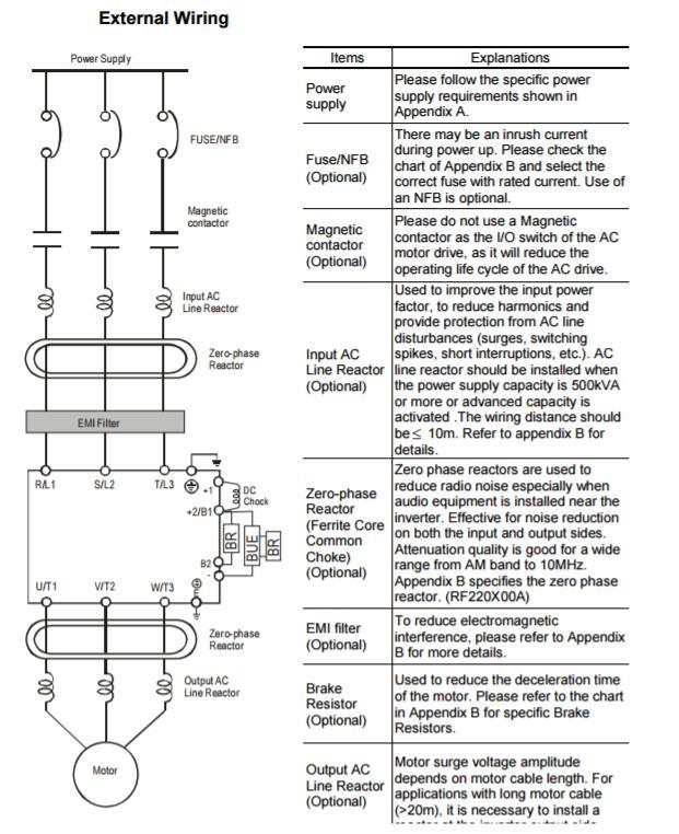
70 61
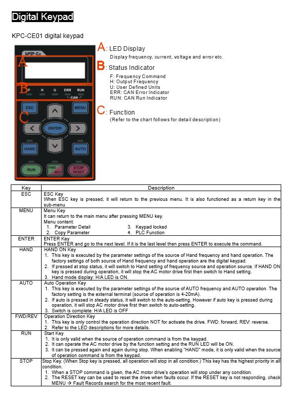
71 62
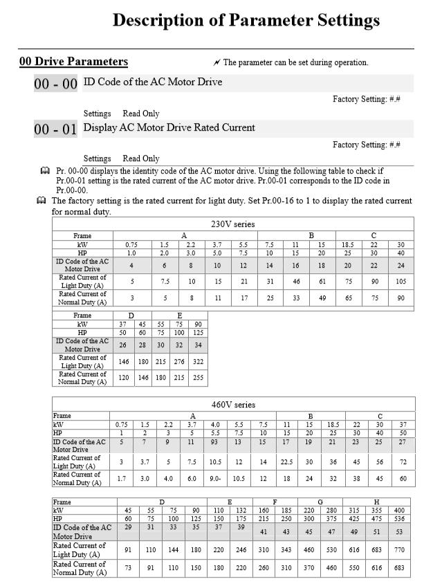
72 63
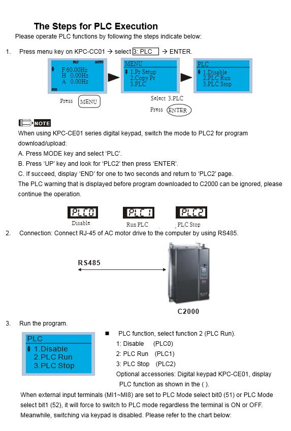
73 64
74 Self-aligning ball bearings EKTN9 65
75 Loadcell specification: 66
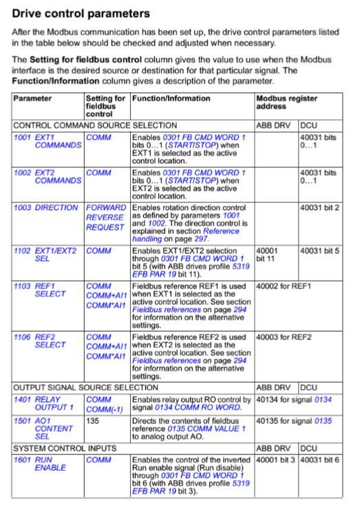
76 67
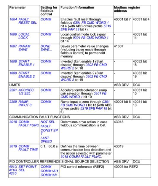
77 68
Technical Guide No. 7. Dimensioning of a Drive system
 Technical Guide No. 7 Dimensioning of a Drive system 2 Technical Guide No.7 - Dimensioning of a Drive system Contents 1. Introduction... 5 2. Drive system... 6 3. General description of a dimensioning
DESIGN OF MACHINE MEMBERS - I
 R10 Set No: 1 III B.Tech. I Semester Regular and Supplementary Examinations, December - 2013 DESIGN OF MACHINE MEMBERS - I (Mechanical Engineering) Time: 3 Hours Max Marks: 75 Answer any FIVE Questions
Ch# 11. Rolling Contact Bearings 28/06/1438. Rolling Contact Bearings. Bearing specialist consider matters such as
 Ch# 11 Rolling Contact Bearings The terms rolling-contact bearings, antifriction bearings, and rolling bearings are all used to describe the class of bearing in which the main load is transferred through
Bearings. Rolling-contact Bearings
 Bearings A bearing is a mechanical element that limits relative motion to only the desired motion and at the same time it reduces the frictional resistance to the desired motion. Depending on the design
Breakthrough in Linear Generator design
 Breakthrough in Linear Generator design Rotary Linear Generator (stroke-rotor generator) By Physicist Wolfhart Willimczik ABSTRACT The law of inductions demands high speed for the moveable electrical parts,
TECHNICAL INFORMATION
 General Nomenclature Spherical Roller Bearings The spherical roller bearing is a combination radial and thrust bearing designed for taking misalignment under load When loads are heavy, alignment of housings
AGN 076 Alternator Bearings
 Application Guidance Notes: Technical Information from Cummins Generator Technologies AGN 076 Alternator Bearings BEARING TYPES In the design of STAMFORD and AvK alternators, the expected types of rotor
Load cells for a Portable Structure
 Load cells for a Portable Structure Load Restoring force Side force We know that a weighing system must be rigid to get good results. We should also know that a three point system is inherently more stable
Application Note : Comparative Motor Technologies
 Application Note : Comparative Motor Technologies Air Motor and Cylinders Air Actuators use compressed air to move a piston for linear motion or turn a turbine for rotary motion. Responsiveness, speed
Planetary Roller Type Traction Drive Unit for Printing Machine
 TECHNICAL REPORT Planetary Roller Type Traction Drive Unit for Printing Machine A. KAWANO This paper describes the issues including the rotation unevenness, transmission torque and service life which should
Review Paper on Design and Development of Coupling Torque Endurance Test Machine with Variable Torque and Chamber Adjustment
 Review Paper on Design and Development of Coupling Torque Endurance Test Machine with Variable Torque and Chamber Adjustment 1. Mr. Borude S.C.(P.G. Student, JSPM s ICOER, Pune), 2.Prof. Biradar N.S.(HOD
AN INTEGRATED MODULAR TEST RIG FOR LANDING GEAR FATIGUE AND STRENGTH TESTING
 ICAS2002 CONGRESS AN INTEGRATED MODULAR TEST RIG FOR LANDING GEAR FATIGUE AND STRENGTH TESTING R. Kyle Schmidt, P. Eng. Messier-Dowty Inc., Ajax, Ontario, Canada Keywords: landing gear, fatigue, strength,
DESIGN CONSIDERATIONS FOR ROTATING UNIONS SEALING TECHNOLOGIES
 DESIGN CONSIDERATIONS FOR ROTATING UNIONS SEALING TECHNOLOGIES Rotating unions convey fluid from a stationary supply line to equipment or a rotating tool. They are critical elements in a variety of applications
ROTARY MODULES. Rotary modules
 Rotary modules Rotary modules ROTARY MODULES Series Size Page Rotary modules RM swivel unit 156 RM 08 160 RM 10 162 RM 12 164 RM 15 168 RM 21 172 RM rotor 176 RM 50 180 RM 110 182 RM 200 184 RM 310 186
Sensor-Bearing Units Steer-By-Wire Modules Mast Height Control units Other sensorized units
 Mechatronics Sensor-Bearing Units... 957 Steer-By-Wire Modules... 967 Mast Height Control units... 969 Other sensorized units... 971 955 Sensor-Bearing Units SKF Sensor-Bearing Units... 958 SKF Explorer
Vibration damping precision couplings
 Vibration damping precision couplings In light of the advantages of elasticity, strength, resilience, and damping effects, elastomer materials are now being used in most areas of mechanical engineering.
Research on Lubricant Leakage in Spiral Groove Bearing
 TECHNICAL REPORT Research on Lubricant Leakage in Spiral Groove Bearing T. OGIMOTO T. TAKAHASHI In recent years, bearings for spindle motors have been required for high-speed rotation with high accuracy
Department of Electrical and Computer Engineering
 Page 1 of 1 Faculty of Engineering, Architecture and Science Department of Electrical and Computer Engineering Course Number EES 612 Course Title Electrical Machines and Actuators Semester/Year Instructor
Chapter 11 Rolling Contact Bearings
 Chapter 11 Rolling Contact Bearings 1 2 Chapter Outline Bearing Types Bearing Life Bearing Load Life at Rated Reliability Bearing Survival: Reliability versus Life Relating Load, Life, and Reliability
Torque Measurement Primer
 Torque Measurement Primer 2/2010 Torque Primer V2 4/22/11 2 So you ve decided you need a torque transducer? Now comes the fun part choosing the right one. The following pages will point out some factors
Step Motor. Mechatronics Device Report Yisheng Zhang 04/02/03. What Is A Step Motor?
 Step Motor What is a Step Motor? How Do They Work? Basic Types: Variable Reluctance, Permanent Magnet, Hybrid Where Are They Used? How Are They Controlled? How To Select A Step Motor and Driver Types of
CHAPTER 1 INTRODUCTION
 1 CHAPTER 1 INTRODUCTION 1.1 ELECTRICAL MOTOR This thesis address the performance analysis of brushless dc (BLDC) motor having new winding method in the stator for reliability requirement of electromechanical
CLASSIFICATION OF ROLLING-ELEMENT BEARINGS
 CLASSIFICATION OF ROLLING-ELEMENT BEARINGS Ball bearings can operate at higher speed in comparison to roller bearings because they have lower friction. In particular, the balls have less viscous resistance
Heavy Duty Ball Screw Linear Actuators
 Heavy Duty Ball Screw Linear Actuators Thrust From 2,000 to 25,000 lbf Heavy Wall Steel Construction Longest Life Simultaneous High Thrust with High Speed Piston with Rugged Anti Rotation Feature Sealed
LESSON Transmission of Power Introduction
 LESSON 3 3.0 Transmission of Power 3.0.1 Introduction Earlier in our previous course units in Agricultural and Biosystems Engineering, we introduced ourselves to the concept of support and process systems
Standard with cone bushing. Backlash-free Safety Clutch
 EAS -Compact ratchetting clutch/synchronous clutch The Backlash-free Safety Clutch for Standard with cone bushing Packaging Machinery Machine Tools Paper Machinery Indexing Drives Servo Motors EAS -NC
TRANSLATION (OR LINEAR)
") 5) Load Bearing Mechanisms Load bearing mechanisms are the structural backbone of any linear / rotary motion system, and are a critical consideration. This section will introduce most of the more common
5) Load Bearing Mechanisms Load bearing mechanisms are the structural backbone of any linear / rotary motion system, and are a critical consideration. This section will introduce most of the more common
QuickStick Repeatability Analysis
 QuickStick Repeatability Analysis Purpose This application note presents the variables that can affect the repeatability of positioning using a QuickStick system. Introduction Repeatability and accuracy
Theory of Machines II EngM323 Laboratory User's manual Version I
 Theory of Machines II EngM323 Laboratory User's manual Version I Table of Contents Experiment /Test No.(1)... 2 Experiment /Test No.(2)... 6 Experiment /Test No.(3)... 12 EngM323 Theory of Machines II
CHAPTER THREE DC MOTOR OVERVIEW AND MATHEMATICAL MODEL
 CHAPTER THREE DC MOTOR OVERVIEW AND MATHEMATICAL MODEL 3.1 Introduction Almost every mechanical movement that we see around us is accomplished by an electric motor. Electric machines are a means of converting
RE / STAR Tolerance Rings STAR Ball Knobs, Knob and Lever Type Handles
 RE 2 970/.99 STAR Tolerance Rings STAR Ball Knobs, Knob and Lever Type Handles STAR Tolerance Rings Product Overview Tolerance rings are made of hard, embossed spring steel strip and belong to the class
Lenze. Global Drive 9300 servo inverters kw
 401 870 Global Drive 9300 servo inverters 0.37 75 kw 9300 servo inverter flexible and modern automation High-performance 9300 servo inverters with a matching motor program form a perfect drive system.
Power Transmission Solutions
 RINGFEDER Products are available from MARYLAND METRICS Power Transmission Solutions 11 2011 Partners for performance RINGFEDER Products are available from MARYLAND METRICS P.O. Box 261 Owings Mills, MD
Permanent Magnet DC Motor
 Renewable Energy Permanent Magnet DC Motor Courseware Sample 86357-F0 A RENEWABLE ENERGY PERMANENT MAGNET DC MOTOR Courseware Sample by the staff of Lab-Volt Ltd. Copyright 2011 Lab-Volt Ltd. All rights
Theory of Machines. CH-1: Fundamentals and type of Mechanisms
 CH-1: Fundamentals and type of Mechanisms 1. Define kinematic link and kinematic chain. 2. Enlist the types of constrained motion. Draw a label sketch of any one. 3. Define (1) Mechanism (2) Inversion
CHAPTER 1 INTRODUCTION
 1 CHAPTER 1 INTRODUCTION 1.1 MOTIVATION OF THE RESEARCH Electrical Machinery is more than 100 years old. While new types of machines have emerged recently (for example stepper motor, switched reluctance
Ball Rail Systems RE / The Drive & Control Company
 Ball Rail Systems RE 82 202/2002-12 The Drive & Control Company Rexroth Linear Motion Technology Ball Rail Systems Roller Rail Systems Standard Ball Rail Systems Super Ball Rail Systems Ball Rail Systems
EMC-HD. C 01_2 Subheadline_15pt/7.2mm
 C Electromechanical 01_1 Headline_36pt/14.4mm Cylinder EMC-HD C 01_2 Subheadline_15pt/7.2mm 2 Elektromechanischer Zylinder EMC-HD Short product name Example: EMC 085 HD 1 System = ElectroMechanical Cylinder
Armature Reaction and Saturation Effect
 Exercise 3-1 Armature Reaction and Saturation Effect EXERCISE OBJECTIVE When you have completed this exercise, you will be able to demonstrate some of the effects of armature reaction and saturation in
Shaft-Hub-Connections
 Stand: 14.01.2010 Shaft-Hub-Connections Shrink Discs Cone Clamping Elements Star Discs 36 Edition 2012/2013 RINGSPANN Eingetragenes Warenzeichen der RINGSPANN GmbH, Bad Homburg Table of Contents Introduction
 DEPARTMENT OF MECHANICAL ENGINEERING Subject code: ME6601 Subject Name: DESIGN OF TRANSMISSION SYSTEMS UNIT-I DESIGN OF TRANSMISSION SYSTEMS FOR FLEXIBLE ELEMENTS 1. What is the effect of centre distance
Unidrive M600 High performance drive for induction and sensorless permanent magnet motors
 Unidrive M600 High performance drive for induction and sensorless permanent magnet motors 0.75 kw - 2.8 MW Heavy Duty (1.0 hp - 4,200 hp) 200 V 400 V 575 V 690 V Unidrive M600 features Easy click-in keypad
Driver Driven. InputSpeed. Gears
 Gears Gears are toothed wheels designed to transmit rotary motion and power from one part of a mechanism to another. They are fitted to shafts with special devices called keys (or splines) that ensure
3. BEARING ARRANGEMENT DESIGN
 3. BEARING ARRANGEMENT DESIGN 3.1 GENERAL PRINCIPLES OF ROLLING BEARING ARRANGEMENT DESIGN Rotating shaft or another component arranged in rolling bearings is guided by them in radial as well as in axial
How to: Test & Evaluate Motors in Your Application
 How to: Test & Evaluate Motors in Your Application Table of Contents 1 INTRODUCTION... 1 2 UNDERSTANDING THE APPLICATION INPUT... 1 2.1 Input Power... 2 2.2 Load & Speed... 3 2.2.1 Starting Torque... 3
Backlash-free safety couplings. Backlash-free safety couplings. Product information. Optimal safety has a name: Guaranteed by two systems:
 ;;Engaged ;;Engaged Backlash-free safety couplings Product information Optimal safety has a name: Backlash-free safety couplings Guaranteed by two systems: ;;;; Locking Locking element - cylinder roller
Technical Explanation for Inverters
 CSM_Inverter_TG_E_1_2 Introduction What Is an Inverter? An inverter controls the frequency of power supplied to an AC motor to control the rotation speed of the motor. Without an inverter, the AC motor
MECHATRONICS LAB MANUAL
 MECHATRONICS LAB MANUAL T.E.(Mechanical) Sem-VI Department of Mechanical Engineering SIESGST, Nerul, Navi Mumbai LIST OF EXPERIMENTS Expt. No. Title Page No. 1. Study of basic principles of sensing and
Special edition paper
 Efforts for Greater Ride Comfort Koji Asano* Yasushi Kajitani* Aiming to improve of ride comfort, we have worked to overcome issues increasing Shinkansen speed including control of vertical and lateral
Features of the LM Guide
 Features of the Functions Required for Linear Guide Surface Large permissible load Highly rigid in all directions High positioning repeatability Running accuracy can be obtained easily High accuracy can
Linear Motion Technology Handbook. The Drive & Control Company
 Linear Motion Technology Handbook The Drive & Control Company 1-2 Bosch Rexroth AG Linear Motion Technology Handbook R310EN 2017 (2006.07) Linear Motion and Assembly Technologies www.boschrexroth.com/brl
Cooling Enhancement of Electric Motors
 Cooling Enhancement of Electric Motors Authors : Yasser G. Dessouky* and Barry W. Williams** Dept. of Computing & Electrical Engineering Heriot-Watt University Riccarton, Edinburgh EH14 4AS, U.K. Fax :
TE 73 TWO ROLLER MACHINE
 TE 73 TWO ROLLER MACHINE Background The TE 73 family of machines dates back to original Plint and Partners Ltd designs from the 1960s. These machines are all to the overhung roller design in which test
EMS ELONGATION MEASUREMENT SYSTEM. Strain measurement system for wind turbines optimizing the control & condition monitoring
 EMS ELONGATION MEASUREMENT SYSTEM Strain measurement system for wind turbines optimizing the control & condition monitoring 2 1 1 3 3 EMS ELONGATION MEASUREMENT SYSTEM 1 Rotor blade Rotor blades are the
Say hello to better web control.
 Say hello to better web control. Montalvo has proven to be a smart investment in applications worldwide. Higher throughput and reduced waste mean that Montalvo products and services can bring to you an
Assemblies for Parallel Kinematics. Frank Dürschmied. INA reprint from Werkstatt und Betrieb Vol. No. 5, May 1999 Carl Hanser Verlag, München
 Assemblies for Parallel Kinematics Frank Dürschmied INA reprint from Werkstatt und Betrieb Vol. No. 5, May 1999 Carl Hanser Verlag, München Assemblies for Parallel Kinematics Frank Dürschmied Joints and
Real-time Simulation of Electric Motors
 Real-time Simulation of Electric Motors SimuleD Developments in the electric drive-train have the highest priority, but all the same proven development methods are not consequently applied. For example
1-3 RAMP AND TORQUE BOOST EXERCISE OBJECTIVE
 1-3 RAMP AND TORQUE BOOST EXERCISE OBJECTIVE Understand the acceleration and deceleration time settings. Introduce the linear and S-shape acceleration and deceleration patterns. Introduce the Torque boost
Compact Modules. with ball screw drive and toothed belt drive R310EN 2602 ( ) The Drive & Control Company
 The Drive & Control Company") with ball screw drive and toothed belt drive R310EN 2602 (2007.02) The Drive & Control Company Bosch Rexroth AG Linear Motion and Assembly Technologies Ball Rail Systems Roller Rail Systems Linear Bushings
with ball screw drive and toothed belt drive R310EN 2602 (2007.02) The Drive & Control Company Bosch Rexroth AG Linear Motion and Assembly Technologies Ball Rail Systems Roller Rail Systems Linear Bushings
Variable Valve Drive From the Concept to Series Approval
 Variable Valve Drive From the Concept to Series Approval New vehicles are subject to ever more stringent limits in consumption cycles and emissions. At the same time, requirements in terms of engine performance,
Linear Flexible Joint Cart Plus Single Inverted Pendulum (LFJC+SIP)
") Linear Motion Servo Plants: IP01 and IP02 Linear Flexible Joint Cart Plus Single Inverted Pendulum (LFJC+SIP) User Manual Table of Contents 1. Linear Flexible Joint Cart Plus Single Inverted Pendulum System
Linear Motion Servo Plants: IP01 and IP02 Linear Flexible Joint Cart Plus Single Inverted Pendulum (LFJC+SIP) User Manual Table of Contents 1. Linear Flexible Joint Cart Plus Single Inverted Pendulum System
PRECISION BELLOWS COUPLINGS
 PRECISION BELLOWS COUPLINGS Bellows couplings are used where precise rotation, high speeds, and dynamic motion must be transmitted. They exhibit zero backlash and a high level of torsional stiffness, offering
LOCKED SERIES. Machine Failures. General Information. set up. maintenance. reconditioning. repair 30.4%
 General Information LOCKED SERIES 2 Lowering machinery process costs is key in today s world. According to a recent study approximately a third of all machine stoppages result in unexpected damage and
Linear Motion and Assembly Technologies Pneumatics Service. forces to the crankshaft s surface to reduce fatigue.
 Electric Drives and Controls Hydraulics Linear Motion and Assembly Technologies Pneumatics Service profile Drive & Control Roll with the Changes: Ingersoll Crankshaft Rolling Machine Uses Integrated Axis
High-force linear motion: How to convert hydraulic cylinders to electric actuators and why.
 High-force linear motion: How to convert from hydraulic cylinders to electric actuators and why. By Aaron Dietrich, Director of Marketing Tolomatic, Inc. About the Author Aaron Dietrich has an extensive
Locking Assemblies Shrink Discs Rigid Couplings.
 M I N I Locking Assemblies Shrink Discs Rigid Couplings www.mav.it our company We are an Italian company world renowned for our creativity and ethics. Established in 1989 we have rapidly built a reputation
R10 Set No: 1 ''' ' '' '' '' Code No: R31033
 R10 Set No: 1 III B.Tech. I Semester Regular and Supplementary Examinations, December - 2013 DYNAMICS OF MACHINERY (Common to Mechanical Engineering and Automobile Engineering) Time: 3 Hours Max Marks:
Driving Characteristics of Cylindrical Linear Synchronous Motor. Motor. 1. Introduction. 2. Configuration of Cylindrical Linear Synchronous 1 / 5
 1 / 5 SANYO DENKI TECHNICAL REPORT No.8 November-1999 General Theses Driving Characteristics of Cylindrical Linear Synchronous Motor Kazuhiro Makiuchi Satoshi Sugita Kenichi Fujisawa Yoshitomo Murayama
Unidrive M700 Class leading performance with onboard real-time Ethernet
 Unidrive M Class leading performance with onboard real-time Ethernet. kw -.8 MW Heavy Duty (. hp -, hp) V V V 9 V Unidrive M features Easy click-in keypad connection Range of multi-language LCD keypads
INDIAN INSTITUTE OF TECHNOLOGY KHARAGPUR NPTEL ONLINE CERTIFICATION COURSE. On Industrial Automation and Control
 INDIAN INSTITUTE OF TECHNOLOGY KHARAGPUR NPTEL ONLINE CERTIFICATION COURSE On Industrial Automation and Control By Prof. S. Mukhopadhyay Department of Electrical Engineering IIT Kharagpur Topic Lecture
Note 8. Electric Actuators
 Note 8 Electric Actuators Department of Mechanical Engineering, University Of Saskatchewan, 57 Campus Drive, Saskatoon, SK S7N 5A9, Canada 1 1. Introduction In a typical closed-loop, or feedback, control
INDEX EASY RAIL: THE SOLUTION IS EASY...D4 EXAMPLES OF LOAD CAPACITIES...D5 ORDER CODES...D6 MOUNTING EXAMPLES...D7 TECHNICAL DATA...
 INDEX EASY RAIL: THE SOLUTION IS EASY...D4 EXAMPLES OF LOAD CAPACITIES...D5 ORDER CODES...D6 MOUNTING EXAMPLES...D7 TECHNICAL DATA...D8 STANDARD CONFIGURATIONS...D10 VERIFICATION UNDER STATIC LOAD...D12
Application Information
 Moog Components Group manufactures a comprehensive line of brush-type and brushless motors, as well as brushless controllers. The purpose of this document is to provide a guide for the selection and application
Principles of Doubly-Fed Induction Generators (DFIG)
") Renewable Energy Principles of Doubly-Fed Induction Generators (DFIG) Courseware Sample 86376-F0 A RENEWABLE ENERGY PRINCIPLES OF DOUBLY-FED INDUCTION GENERATORS (DFIG) Courseware Sample by the staff
Renewable Energy Principles of Doubly-Fed Induction Generators (DFIG) Courseware Sample 86376-F0 A RENEWABLE ENERGY PRINCIPLES OF DOUBLY-FED INDUCTION GENERATORS (DFIG) Courseware Sample by the staff
Proven to be better. Development trends in industrial rolling bearings
 Proven to be better Development trends in industrial rolling bearings Contents 1. General trends in power transmission and in machine construction and plant engineering Page 3 2. General trends in rolling
Efficient and Effective bearing performance evaluation
 Efficient and Effective bearing performance evaluation The right software platform for dedicated technical questions, based on the right knowledge and design criteria A typical design process Changes SKF
Automation is the techniques and equipment used to achieve automatic operation or control.
 VALVE AUTOMATION What is Automation? Automation is the techniques and equipment used to achieve automatic operation or control. Automation is an automatic operation and control of machinery or processes
PUMP HEART OF PLUMBING SYSTEM V.SRINIVAS
 PUMP HEART OF PLUMBING SYSTEM V.SRINIVAS Pump is the most important element in the Plumbing system and may be considered as its Heart. Majority of Energy in Plumbing systems is consumed by Pumps. It is
C-SERIES S-SERIES. Metric Machine Screw Jacks EMA LINEAR ACTUATORS
 C-SERIES S-SERIES Metric Machine Screw Jacks EMA LINEAR ACTUATORS Power Jacks has a proud engineering heritage dating from the earliest years of the 20th Century. A heritage that is about excellence: about
Innovative Testing Equipment. Torque sensors Vehicle Applications Actuators
 Innovative Testing Equipment Torque sensors Vehicle Applications Actuators Custom-made measuring solutions As a leading drivetrain testing company, ATESTEO specialises in drivetrain and transmission testing
KTR Torque Limiters Overload Protection Systems
 KT Torque Limiters Overload Protection Systems UFLEX - Friction Disk - Zero Backlash Ball Detent KT SI - Ball/oller Bearing Style KT SI Compact - Zero Backlash Ball Detent Catalog Contents (Metric) Page
ME 343: Mechanical Design-3
 What are bearings? ME 343: Mechanical Design-3 Bearings Dr. Aly Mousaad Aly Department of Mechanical Engineering Faculty of Engineering, Alexandria University Machines with moving parts must have some
White paper: Pneumatics or electrics important criteria when choosing technology
 White paper: Pneumatics or electrics important criteria when choosing technology The requirements for modern production plants are becoming increasingly complex. It is therefore essential that the drive
Testing Of Fluid Viscous Damper
 Testing Of Fluid Viscous Damper Feng Qian & Sunwei Ding, Jingjing Song Shanghai Research Institute of Materials, China Dr. Chien-Chih Chen US.VF Corp, Omni Device, China SUMMARY: The Fluid Viscous Damper
ME 343: Mechanical Design-3. Department of Mechanical Engineering Faculty of Engineering, Alexandria University
 ME 343: Mechanical Design-3 Bearings Dr Aly Mousaad Aly Dr. Aly Mousaad Aly Department of Mechanical Engineering Faculty of Engineering, Alexandria University What are bearings? Machines with moving parts
Six keys to achieving better precision in linear motion control applications
 profile Drive & Control Six keys to achieving better precision in linear motion control applications Achieving precise linear motion Consider these factors when specifying linear motion systems: Equipped
Chapter 7: DC Motors and Transmissions. 7.1: Basic Definitions and Concepts
 Chapter 7: DC Motors and Transmissions Electric motors are one of the most common types of actuators found in robotics. Using them effectively will allow your robot to take action based on the direction
RoaDyn S635 System 2000
 Force RoaDyn S635 System 2000 Wheel Force Sensor for Heavy PassCars and High Performance Sports Cars Wheel force sensor for measuring three forces and three moments on a rotating wheel; a major constituent
CONTENT. 1. Syllabus 2. Introduction 3. Shaft 4. Coupling. Rigid coupling. Flange coupling. Sleeve (or) muff coupling Split muff coupling
 muff coupling Split muff coupling") UNIT II 1. Syllabus 2. Introduction 3. Shaft 4. Coupling Rigid coupling CONTENT Flange coupling Protected flange coupling Unprotected flange coupling Marine type flange coupling Sleeve (or) muff coupling
UNIT II 1. Syllabus 2. Introduction 3. Shaft 4. Coupling Rigid coupling CONTENT Flange coupling Protected flange coupling Unprotected flange coupling Marine type flange coupling Sleeve (or) muff coupling
Dev Bhoomi Institute Of Technology LABORATORY Department of Electrical And Electronics Engg. Electro-mechanical Energy Conversion II
 REV. NO. : REV. DATE : PAGE: 1 Electro-mechanical Energy Conversion II 1. To perform no load and blocked rotor tests on a three phase squirrel cage induction motor and determine equivalent circuit. 2.
Faraday's Law of Induction
 Purpose Theory Faraday's Law of Induction a. To investigate the emf induced in a coil that is swinging through a magnetic field; b. To investigate the energy conversion from mechanical energy to electrical
Mechanical Considerations for Servo Motor and Gearhead Sizing
 PDHonline Course M298 (3 PDH) Mechanical Considerations for Servo Motor and Gearhead Sizing Instructor: Chad A. Thompson, P.E. 2012 PDH Online PDH Center 5272 Meadow Estates Drive Fairfax, VA 22030-6658
GSM. Modular Design. Versions of the series. Type GSM. Gripper type P Z W R. Size. {} AS IS without O.D. clamping I.D. clamping
 GSM Pneumatic Gripper-Swivel System Modular Design Versions of the series Type GSM Gripper type P Z W R Size 32 40 50 64 30 38 45 16 20 25 32 40 16 20 25 32 40 Gripping force safety device {} AS IS without
Lab 6: Wind Turbine Generators
 Lab 6: Wind Turbine Generators Name: Pre Lab Tip speed ratio: Tip speed ratio (TSR) is defined as: Ω, where Ω=angular velocity of wind, and R=radius of rotor (blade length). If the rotational speed of
Design and Vibrational Analysis of Flexible Coupling (Pin-type)
") Design and Vibrational Analysis of Flexible Coupling (Pin-type) 1 S.BASKARAN, ARUN.S 1 Assistant professor Department of Mechanical Engineering, KSR Institute for Engineering and Technology, Tiruchengode,
Design and Vibrational Analysis of Flexible Coupling (Pin-type) 1 S.BASKARAN, ARUN.S 1 Assistant professor Department of Mechanical Engineering, KSR Institute for Engineering and Technology, Tiruchengode,
CONTRIBUTION TO THE CINEMATIC AND DYNAMIC STUDIES OF HYDRAULIC RADIAL PISTON MOTORS.
 Ing. MIRCEA-TRAIAN CHIMA CONTRIBUTION TO THE CINEMATIC AND DYNAMIC STUDIES OF HYDRAULIC RADIAL PISTON MOTORS. PhD Thesis Abstract Advisor, Prof. dr. ing. matem. Nicolae URSU-FISCHER D.H.C. Cluj-Napoca
DHANALAKSHMI COLLEGE OF ENGINEERING
 DHANALAKSHMI COLLEGE OF ENGINEERING (Dr.VPR Nagar, Manimangalam, Tambaram) Chennai - 601 301 DEPARTMENT OF MECHANICAL ENGINEERING III YEAR MECHANICAL - VI SEMESTER ME 6601 DESIGN OF TRANSMISSION SYSTEMS
Linear Actuators for On/Off-Highway Vehicles
 Linear Actuators for On/Off-Highway Vehicles Thomson Actuators Set the Standard in On-Off Highway Vehicles We are the original actuator manufacturer. For over 40 years, our engineers have worked to design
Comparison Chart. extremely difficult. Finally, separated components can rarely be re-used.
 JAN 2014 Traditional Connections Why Go Keyless Keyed Bushing Systems Both QD and Taper-Lock bushing and weld-on hub systems are popular component mounting technologies. Yet both are ultimately keyed connections
Interface Webinar Wednesday. with Keith Skidmore
 Interface Webinar Wednesday Torque 101 with Keith Skidmore www.interfaceforce.com 480 948 5555 Definitions What is a Torque Transducer? Rotary vs. Reaction Shaft vs. Flange Couplings Floating vs. Fixed