Shocker XL Installation Manual
|
|
|
- Randell Lee
- 6 years ago
- Views:
Transcription


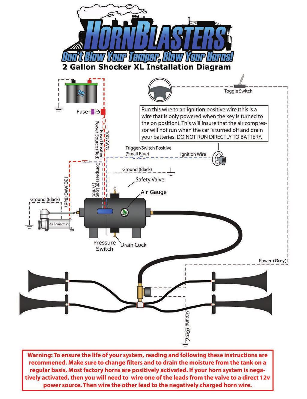
1 Shocker XL Installation Manual 232, 240, 244, 248 WARNING: To ensure the longevity of your system, reading and following these instructions are recommended. Make sure to change filters and to drain the moisture from your tank on a regular basis.
2 HornBlasters Shocker XL Installation Guide Before Getting Started Read over the entire instruction guide before you begin your installation. Kit Contents: HornBlasters Shocker Horns Viair 325, 400, 444, volt Air Compressor HornAir 2 gallon 6 port tank Electric 1/2 Solenoid Valve Fittings, Air line, Wiring Kit HornBlasters 250 PSI Gauge HornBlasters 150 PSI Pressure Switch with built in Relay Support Line: +1 (813) Fax Line: +1 (813) support@hornblasters.com IMPORTANT: This complete train horn kit uses 12 volt DC components. Only install this kit with a 12 volt DC power source. Important Safety Instructions CAUTION: To prevent the risk of electrical shock or electrocution: Do not disassemble any electrical components of this horn kit (air compressor, air valve, pressure switch). Do not attempt repairs or modifications of any component. Please refer to qualified service agencies for all service and repairs. Do not operate any component where it can fall or be submerged into water or any kind of liquid. Do not reach for any component that has fallen or been submerged into water or any kind of liquid. Use the included components with 12 volt DC systems only. Do not leave the air system unattended during use. WARNING: To prevent injury: Never allow children to operate the compressor or air horn. Use close supervision when operating this equipment near children. The air compressor will become very HOT during and immediately after operation. Do not touch any part of the compressor with your bare hands during or immediately after use. Do not use this product near open flames or explosive materials or where aerosol products are being used. Do not operate this product where oxygen is being administered. Do not pump anything other than atmospheric air. Never use this product while sleepy or drowsy. Do not use any tools or attachments with the supplied air source unit without first determining maximum air pressure for that tool or attachment. Never point any air nozzle or air sprayer toward another person or any part of your body. The included compressor is equipped with an automatic reset thermal protector and can automatically restart after the thermal protector resets. Always cut off power source when thermal protector becomes activated. Use only in well ventilated areas. Do not sound the air horn(s) in close proximity to another person s or your own ear(s). Do not fill the included air tank above 150 PSI. Doing so may result in death or serious injury. 1
3 Safety During Installation Disconnect the ground of your battery before beginning your installation. Use eye protection when operating drills. Take your time and do not rush your installation. Installing Your Train Horn Kit Planning Your Installation This is the most important step in your installation. Plan out the location of each component before starting your installation. Make sure you have enough airline and wire to install the system before beginning the installation. Make sure mounting locations are secure and clear of debris. Try to keep the supply wire to the compressor as short as possible. Wires lose voltage over distance therefore shorter wires will result in better performance. Mount your air compressor in a location that is as cool as possible and away from heat sources. This will make your compressor run cooler and last longer. Your air compressor must be mounted upright or horizontally but never upside down to allow the compressor to cool properly. To increase performance make sure the compressor is mounted upright. Your air compressor should be mounted above the tank. Failure to mount the unit in this position will allow any condensation buildup to drain back in to the compressor and foul its components. Teflon tape or a locking compound should be used on every fitting in your air system to prevent air leaks; unless a white or red PTFE paste is already applied. Air valves can be mounted in any position but are recommended to be mounted vertically with the pilot housing above the valve body. Make sure the directional arrow is pointed towards the horns. Use the supplied 10 gauge wire or thicker (lower gauge #) wire to power your air compressor. We recommend installing our kits in a certain configuration. With the 2 gallon tank, you have two 1/2 ports and four 1/4 ports. Install the tank in position where one 1/4 port is facing down for the drain cock. From there place the gauge, pressure switch and safety blow off valve in the remaining three 1/4 ports. For the two 1/2 ports, one of them will have the 1/2 to 1/4 female reducer bushing for the compressor (1/2 to 3/8 for the Viair 480c) and the other 1/2 port is for the 1/2 PTC to 1/2 NPT M fitting for the horns. Recommended Tools 3/8 Long Socket (Horn Front Mount) 1/2 Long Socket (Horn Rear Mount) 1/2 Wrench 9/16 Wrench (1/4 NPT Fittings) 7/8 Wrench (1/2 Banjo) 10mm Wrench or Socket (Air Source Mounting) 12mm Wrench Drill (3/16 & 7/16 Bits) Wire Cutter/Stripper Tubing Cutter/Razor Eye Protection I. Installing Your Hornblasters Train Horns Locate an area for your horns that is dry and free from debris. The horns can be mounted in any direction and still be heard from all around. The horns should not be mounted where they will be completely submerged or will receive any kind of impact. Horns may be mounted directly to your vehicle, on a medium such as grommet strips (plumber s strap), sheet metal or any sort of custom bracket. Note that air line will be running to each horns rear mount from the banjo. 1. Locate a secure, dry, and safe position for your horns. 2. Drill a 3/16 hole for the front mount of each horn and a 7/16 hole for each rear mount. 3. Secure the horn using the supplied mounting hardware. 2
4 II. Installing Your Air Compressor Pump Locate a flat and secure installation area that will remain free of dust, dirt, and debris (your compressors performance is directly affected by air quality). Try to keep the distance of the unit from the battery to a minimum to keep your compressor running at maximum performance. 1. Disconnect the ground cable from the vehicle s battery. 2. Position the unit in the desired location and secure it using the supplied mounting hardware (8mm). 3. Remove the orange plug in the compressor s inlet and install the remotely mountable air intake assembly. Using the included 3/8 OD air line and fittings you may relocate the air filter up to 6 feet away from the air compressor. 4. Only hand tighten the check valve. III. Installing Your Air Tank Locate a secure area close to your air compressor to mount your air tank. The leader hose of the compressor should be able to reach an available port on the air tank with some slack. 1. Position the tank in its desired location and secure it using standard mounting hardware. IV. Installing Your Air Tubing & Air Valve Before cutting any air tubing, make sure to double check your measurements. Make sure to cut equal lengths of air line to connect each horn to the manifold or the horns may sound at different times. We recommend cutting your lengths with at least an extra inch per line just to be safe. Unlike compression fittings, the push to pull connectors can be used multiple times. The air valve should connect to the center fitting of the 4-point banjo fitting. When threading any fittings make sure to use Teflon tape or lock-tight to prevent air leaks. Some fittings may already have pipe sealant applied on their threads for your convenience. The air valve may be mounted in any direction but it is preferred that it is mounted vertically. Your tank has two 1/2 NPT ports and four 1/4 NPT ports. Your train horn kit should use one of the 1/2 ports and the other may be reduced to 1/4 reducer bushing if necessary. IMPORTANT: Do not rotate or remove the inline check valve in the compressor s leader hose. Doing so will damage its seals and will result in damage to your air compressor and voiding of your warranty. IMPORTANT: Do not make any kinks in your air line. Doing so will disrupt air flow and the damage is irreversible. Air Compressor to Tank: [Air Compressor]» [1/4 Leader Hose]» [1/2 to 1/4 NPT F Reducer]» [Air Tank] 1. Carefully connect the air compressor leader hose to the 1/2 to 1/4 NPT F Reducer bushing that is located on either end of the tank using Teflon tape or paste on the treading. When installing the leader hose DO NOT move the inline check valve located just above the swivel fitting. a. If installing a Viair 480c, you will use a 1/2 to 3/8 NPT F Reducer. 2. Locate a secure location to mount the leader hose using the bracket provided. Avoid locations where the leader hose may become tangled with wires and other hoses. a. When mounting the bracket, drill a hole with a 3/16 drill bit and put the self-anchoring hose bracket into the hole. Air Horns to Tank: [Air Tank]» [1/2 NPT M to 1/2 PTC Fitting]» [1/2 Air Line]» [1/2 NPT M to 1/2 PTC Fitting]» [Air Valve]» [1/2 to 4x 5/16 NPT M Banjo Fitting]» [5/16 Air Line]» [5/16in P2P to 1/8in NPT F Elbow]» [Rear Horn Mount] 1. Plan out the fittings placement before you begin and make sure you understand the correct order. 2. Make sure that your tank is empty of air and that the compressor is not running during installation. 3. Start by cutting equal lengths of 5/16 tubing to run from each horn to the banjo fitting. 4. Install your banjo fitting into the outlet port of your 1/2 air valve. If the valve has a directional arrow on its body, the arrow starts with the inlet and points out the outlet; the arrow should point towards your horns. 5. Plumb each horn to the banjo fitting, making sure that the lines are inserted firmly into their sockets. You do not use Teflon tape or pipe sealant with the PVC fittings. 6. Finally connect your air valves inlet port to your air tank using 1/2 air line using the 1/2 M NPT to 1/2 PTC fittings. Make sure to use a side or top port on your tank so that condensation will not drain in to your air valve. 3
5 Drain Cock to Tank: 1. Install the drain cock into the bottom 1/4 port on the bottom of the tank. If the drain cock already has sealant on its threads it is unnecessary to use Teflon tape on the threads. Pressure Switch in to Tank: [Air Tank]» [1/4 NPT Port]» [Pressure Switch unit] 1. Install the pressure switch unit into an available port on the air tank using Teflon tape or pipe sealant on the threading. Make sure to mount the pressure switch on the side or the top of the tank so that condensation will not be able to drain in to the pressure switch. Hand tighten only, and don't tighten by twisting the box. Safety Valve in Tank: 1. Install the safety valve into any spare 1/4 NPT port on your air tank. If the safety valve already has sealant on its threads, it is unnecessary to use Teflon tape on the threads. Do not mount on bottom of tank, and do not use as drain. Air Gauge in Tank: 1. Install the Hornblasters Air Gauge in the last remaining 1/4 NPT port using Teflon tape or paste on the threads. Make sure to mount the air pressure gauge on the side or the top of the tank so that condensation will not be able to drain in to the gauge. V. Wiring Your Valve & Air Source Unit Your train horn kit will use two completely independent circuits. One circuit will connect your horn trigger (push-button switch, or toggled factory button) to your electric solenoid valve. The other circuit will connect your accessory trigger (ignition wire, accessory wire) to your air source kit. If you have trouble with wiring, you can find a wiring diagram of your vehicle on This can help you locate certain wires to properly and safely install your train horn kit! Valve Wiring Flow Chart (Circuit 1) [Factory Horn Wire]» [Toggle Switch)» [Air Valve]» [Ground] Circuit 1 1. Begin by wiring your horn trigger. a. If you are intending to use your factory horn switch, start by locating the load wire of the horn button (positive when horn button is depressed in a standard vehicle) and wiring it to the included toggle switch (any side). b. If you are going to use a push button switch (intermittent toggle switch) wire a fused (5A) wire from any 12 volt source desired (battery) to your switch (any side). 2. Wire your switch to any lead of your air valve. 3. Wire the other side of the air valve to ground. 4. Test your circuit by activating your trigger and listening for a quiet click sound from the valve. Circuit 2 1. Find the accessory line in your vehicle (this is a wire that is only powered when the key is turned to the accessory or on positions. 2. Using the supplied 18 gauge wire connect the accessory wire to the BLUE ignition positive wire from the pressure switch. 3. Ground your pressure switch using the small BLACK wire from the pressure switch. 4. Locate your 12v DC power source that is capable of handling a 26 amp load. 5. Run the supplied 10 gauge or bigger wire to the inline fuse holder using the supplied 35 amp fuse. Then connect this to the RED fused 12v positive wire from the pressure switch. 6. Connect the pressure switch to the air compressor using the WHITE compressor wire from the pressure switch to the RED wire from the compressor. 7. Ground the other side of your air compressor using the BLACK wire. 8. Your compressor system will now turn on automatically when power is on (key is in Accessory or On position) and automatically turn itself off upon reaching pressure limits. You re Done! It s time to test your horns! Share your install photos on our Facebook fanpage at and don t forget to check out the largest train horn community on the internet! 4
6 Maintenance & Tips Disconnect electrical components and drain you air system before performing maintenance. General Air Horn System Maintenance Check your air horns for debris when appropriate and at least once a month and clean when necessary. Drain your air system at least every other week, to remove any condensation buildup on the inside of your air tank. Make sure your air compressor is clean and free from debris at all times. Periodically change your two stage air filter on your compressor. Tips Make sure your engine is running when your air compressors is in use to insure proper voltage and to prevent damage to your system. Do not run your compressor above its maximum rated working pressure. Doing so will not only void you warranty, but may also damage your compressor. The air horns are pre-tuned to a locomotive chord and to their loudest possible tone. Do not adjust the tuning screw on the horns. Doing so will void your warranty and may damage the horns if improperly adjusted. Troubleshooting Problem Air horn will not sound. Horn tone changes when sounded Excessive moisture in horn or safety discharge. Compressor will not run. Thermal overload protector cuts out repeatedly. Excessive knocking or rattling Tank pressure drops when compressor shuts off Compressor runs continuously and air flow lower than normal Compressor runs continuously causing safety valve to open. Can t Figure It Out? 1. No pressure in air tank. 2. No power or toggle switch in Off position. 3. Blown fuse. 4. Loose connections or bad ground in air valve circuit (circuit 1). 1. A side fitting was used to connect the air source (line from valve) to the 4-point banjo manifold. 2. Air line connecting the horns is not of equal length. 1. Excessive water in tank. 2. Compressor is exposed to high humidity. 1. No power or toggle switch in Off position. 2. Blown fuse. 3. Motor overheat. 4. Faulty pressure switch. 1. Lack of proper ventilation/ambient temperature too high. 2. Compressor valves failed. 1. Loose mounting bolts. 2. Worn bearing on eccentric or motor shaft. 3. Cylinder or piston ring is worn. 1. Loose drain cock. 2. Air valve or check valve is leaking. 3. Loose connections. 4. Defective safety valve. 1. Excessive air usage. 2. Loose connections. 3. Worn piston ring or inlet valve. 4. Clogged air filter element. 1. Faulty pressure switch. 2. Defective safety valve. 1. Check that air tank is pressurized. 2. Make sure all toggle switches are on. 3. Disconnect electrical components and replace fuse. 4. Check that all electrical circuits are secure and not corroded. 1. Check that air source (line coming from valve) is entering the center fitting of the 4-point banjo manifold. 2. Check that the air line connecting each horn to the 4-point banjo manifold is of equal length. 1. Depressurize tank using safety, then drain tank. Tilt the tank to drain moisture and drain more frequently. 2. Move the compressor to an area with less humidity. 1. Make sure all toggle switches are on. 2. Disconnect compressor from power & replace fuse (35A). 3. Let compressor cool off for about 30 minutes for thermal overload switch to reset. 4. Replace pressure switch. 1. Move compressor to a well ventilated area or an area with a lower ambient temperature. 2. Replace air compressor. 1. Tighten bolts. 2. Replace compressor. 3. Replace compressor. 1. Tighten drain cock. 2. Replace air valve or check valve. 3. Check all air connections with soap and water solution and tighten as necessary. 4. Replace safety valve. 1. Decrease air usage. 2. Check all connections with soap and water solution and tighten as necessary. 3. Replace compressor 4. Replace air filter element. 1. Replace pressure switch. 2. Replace safety valve. No problem! Give us a call at , or at support@hornblasters.com and we ll be more than happy to help you fix your system. Also feel free to visit our online horn community, for more information. 5
7 Photograph & Media Submission Guidelines Send in your installation photographs and any other media for a chance to be featured on our web site! General Photograph Submission Guidelines Please submit clean, concise photographs. Make sure your subject is clearly visible and in focus. You may submit and digital image format either via at media@hornblasters.com, or via digital media (CD, DVD, etc). Make sure to include some kind of personal information with your submission. We would love to be able to contact you and thank you. Installation Gallery Submission Guidelines Please take at least one photo of each major components of your installation (horns, compressor, tank, valve, switches, etc). Don t forget to send us some shots of your vehicle too! If we can't tell what the install is on, we probably won t post it. Include as much installation information as possible. Who installed the system and when was it installed? How long did the install take? What is the year, model, and style of your vehicle? If you took your system to a shop, would you recommend the shop to others? Do you have any comments or tips about the installation? Anything else you want to tell us, we always appreciate your feedback! Optionally include a little personal information: Your name (if you would like your full name to be displayed, you have to let us know!) General Video Submission Guidelines We accept all kinds of media. Please provide us with the highest quality media to prevent video degradation. We can read all formats of video. We recommend using either the default your camera records with; or if you are compressing the video, we recommend using AVI containers and Xvid, Divx, or a MPEG codec. We recommend AGAINST using any kind of Windows Media*, Real Media*, or Apple QuickTime* formats. You may submit any digital image format either via at media@hornblasters.com, or via digital media (CD, DVD, etc). Make sure to include some kind of personal information with your submission. We would love to be able to contact you and thank you! *Windows, Windows Media, Real, Real Media, Apple, and QuickTime are all registered trademarks and copyright of their respective owners. Get Involved In The Train Horn Community No matter what your take is on your new train horn kit, it s always good to have someone to share your stories with. Trainhornforums.com is the largest train horn community online and provides a place to share photos of your ride, post videos, catch up with other train horn and HornBlasters fans, meet other train horn enthusiasts, or even find help with a complicated question. Go online to and sign up #hornblasters /hornblasters Make sure to follow us on all the popular social media! Facebook, Vine, Twitter, Youtube, and Instagram. Show off your install and tag us in all your photos! 6
8

9
Shocker XL Installation Manual
 Shocker XL Installation Manual 232, 240, 244, 248 WARNING: To ensure the longevity of your system, reading and following these instructions are recommended. Make sure to change filters and to drain the
Outlaw Installation Manual
 Outlaw Installation Manual 127CX & 228VX WARNING: To ensure the longevity of your system, reading and following these instructions are recommended. Make sure to change filters and to drain the moisture
HORNBLASTERSTM. OutLaw 232 TM. Locomotive Air Horn System Manual
 HORNBLASTERSTM OutLaw 232 TM Locomotive Air Horn System Manual HornBlastersTM Outlaw 232 TM Locomotive Air Horn System Installation Guide Before Getting Started Read over the entire instruction guide before
SHOCKER XL INSTALLATION MANUAL 232, 240, 244, 248
 SHOCKER XL INSTALLATION MANUAL 232, 240, 244, 248 WARNING: To ensure the longevity of your system, reading and following these instructions are recommended. Make sure to change filters and to drain the
HORNBLASTERS. Five Gallon Conductor s Special Installation Manual
 HORNBLASTERS Five Gallon Conductor s Special Installation Manual HornBlasters Five Gallon Conductor s Special Installation Guide Support Line: +1 (813) 783-8058 Fax Line: +1 (813) 783-2407 support@hornblasters.com
HORNBLASTERS. Shocker Classic 228VX Installation Manual
 Shocker Classic 228VX Installation Manual HornBlasters Shocker Classic 228VX Train Horn Kit Installation Guide Support Line: +1 (877) 209-8179 Fax Line: +1 (813) 783-2407 support@hornblasters.com www.hornblasters.com/support
OUTLAW INSTALLATION MANUAL 232, 240, 244, 248
 OUTLAW INSTALLATION MANUAL 232, 240, 244, 248 WARNING: To ensure the longevity of your system, reading and following these instructions are recommended. Make sure to change filters and to drain the moisture
HORNBLASTERS. Nathan AirChime K5 Train Horn Kit Installation Manual
 HORNBLASTERS Nathan AirChime K5 Train Horn Kit Installation Manual HornBlasters K5 Train Horn Kit Installation Guide Support Line: +1 (813) 783-8058 Fax Line: +1 (813) 783-2407 support@hornblasters.com
40041 Heavy Duty ADA System with Booster Bracket for JK Heavy Duty ADA System with Booster Bracket for 2012 to Current JK
 40041 Heavy Duty ADA System with Booster Bracket for 2007-2011 JK 40044 Heavy Duty ADA System with Booster Bracket for 2012 to Current JK 40049 Heavy Duty ADA System Universal for all vehicles (booster
HEAVY DUTY ONBOARD AIR SYSTEM
 HEAVY DUTY ONBOARD AIR SYSTEM PART NO. 10005 IMPORTANT: It is essential that you and any other operator of this product read and understand the contents of this manual before installing and using this
HEAVY DUTY ONBOARD AIR SYSTEM PART NO
 IMPORTANT: It is essential that you and any other operator of this product read and understand the contents of this manual before installing and using this product. SAVE THIS MANUAL FOR FUTURE REFERENCE
MEDIUM DUTY ONBOARD AIR SYSTEM
 MEDIUM DUTY ONBOARD AIR SYSTEM PART NO. 10003 IMPORTANT: It is essential that you and any other operator of this product read and understand the contents of this manual before installing and using this
MODEL NUMBER: MEDIUM DUTY ONBOARD AIR SYSTEM
 MODEL NUMBER: 10003 MEDIUM DUTY ONBOARD AIR SYSTEM IMPORTANT: It is essential that you and any other operator of this product read and understand the contents of this manual before installing and using
P.A. System Installation Manual
 P.A. System Installation Manual 100 Watt Public Address w/ Sirens WARNING: To ensure the longevity of your system, reading and following these instructions are recommended. Make sure to change filters
Model 6275RC 50% Duty Cycle Compressor
 Model 6275RC 50% Duty Cycle Compressor IMPORTANT: It is essential that you and any other operator of this product read and understand the contents of this manual before installing and using this product.
CONSTANT DUTY ONBOARD AIR SYSTEM
 Thank you for purchasing this complete, self-contained onboard air system. Contained in one package, you ll find everything you ll need to install a high performance, onboard air source for your vehicle.
HEAVY DUTY ONBOARD AIR SYSTEM
 Thank you for purchasing this complete, self-contained onboard air system. Contained in one package, you ll find everything you ll need to install a high performance, onboard air source for your vehicle.
6 Litre Oil-Less Air Compressor
 Operator s Manual 6 Litre Oil-Less Air Compressor WARNING! Before using this appliance, read the Operator s manual and follow all its safety rules and instructions. SPECIFICATION HWKAC1 1.1 kw / 1.5 HP
INSTALLATION AND USER MANUAL
 INSTALLATION AND USER MANUAL SDKIT-730 & SDKIT-734 100% Bolt-On 150 PSI Train Horn System for 2011-2015 F-250 & F-350 Super Duty P/N SDKIT-730 P/N SDKIT-734 Thank you for purchasing a Kleinn Air Horns
ARC4000e 4 wheel compressor system w / 4 way Ride Pro controller
 350 S. St. Charles St. Jasper, In. 47546 Ph. 812.482.2932 Fax 812.634.6632 on the internet: www.ridetech.com ARC4000e 4 wheel compressor system w / 4 way Ride Pro controller 1 ARC5001 Compressor 1 CON6000
6L Oil-less Air Compressor 53103
 6L Oil-less Air Compressor 53103 Operating Instructions Please read and save these instructions before attempting to assemble, install, operate or maintain the product. Protect yourself and others by observing
SPECIFICATIONS Horsepower: 1.5 HP Running Maximum PSI: 125 PSI Tank Capacity: 15 Gallons CFM: 6 40 PSI 5 90 PSI
 15 GALLON AIR COMPRESSOR Model: 7678 DO NOT RETURN TO STORE Please call 800-348-5004 for parts and service CALIFORNIA PROPOSITION 65 WARNING: You can create dust when you cut, sand, drill or grind materials
ONBOARD AIR SYSTEM FOR ALL VEHICLES APPLICATIONS
 ONBOARD SYSTEM FOR ALL VEHICLES APPLICATIONS Thank you and congratulations on the purchase of a Pacbrake onboard air system. Please read the manual prior to starting to ensure you can complete the installation
GMTRK1 BOLT-ON TRAIN HORN SYSTEM INSTALLATION INSTRUCTIONS. For GM & GMC Trucks & SUVS
 GMTRK1 BOLT-ON TRAIN HORN SYSTEM INSTALLATION INSTRUCTIONS For 2007-2017 GM & GMC Trucks & SUVS The GMTRK-1 System comes with a custom battery tray to hold the air compressor and air tank. The horns will
350 S. St. Charles St. Jasper, In Ph Fax
 350 S. St. Charles St. Jasper, In. 47546 Ph. 812.482.2932 Fax 812.634.6632 www.ridetech.com Part # 30154700 Big Red Analog Compressor Kit Components: 2 31920020 Thomas compressor 1 31915100 5 gallon aluminum
INSTALLATION INSTRUCTIONS For Model 855 Wolo Express TM
 INSTALLATION INSTRUCTIONS For Model 855 Wolo Express TM 12-Volt Train Horn Your purchase of a WOLO EXPRESS TRAIN HORN is the choice that will complement your vehicle. Wolo s products are manufactured with
Installation Instructions Diesel Nitrous System (#82028)
") Installation Instructions Diesel Nitrous System (#82028) Thank you for choosing ZEX. If at any time you have questions regarding this or any of our products, please call our Nitrous Help support line at
Installation Instructions Diesel Nitrous System (#82028) Thank you for choosing ZEX. If at any time you have questions regarding this or any of our products, please call our Nitrous Help support line at
HP10098 BASIC INDEPENDENT AIR SPRING ACTIVATION KIT
 HP10098 BASIC INDEPENDENT AIR SPRING ACTIVATION KIT Thank you and congratulations on the purchase of a Pacbrake basic independent air spring activation kit. Please read the entire installation manual prior
Part # Series RidePro 4 Way Compressor System 3 Gallon Tank Analog Gauges
 350 S. St. Charles St. Jasper, In. 47546 Ph. 812.482.2932 Fax 812.634.6632 www.ridetech.com Part # 30154000 4000 Series RidePro 4 Way Compressor System 3 Gallon Tank Analog Gauges Components: 1 31920020
Part # Mopar LX Level 1 Air Suspension System
 Part # 13040199 05-14 Mopar LX Level 1 Air Suspension System Front Components: 1 1304409 Front RQ ShockWave Kit for Stock Lower Arms Rear Components: 1 13044099 Rear CoolRide Kit 1 13040709 RQ Series Rear
Single shot MODEL EGA700 OWNERS MANUAL
 Single shot AIR OPERATED GREASE GUN MODEL EGA700 OWNERS MANUAL www.eaglecompressor.com 1-800-551-2406 READ THE ENTIRE MANUAL BEFORE PUTTING THIS TOOL IN SERVICE Limited Air Tool Warranty Eagle warrants
M-3025CB-AV Fuel Pump
 SAVE THESE INSTRUCTIONS M-3025CB-AV Fuel Pump Owner s Manual TABLE OF CONTENTS General Information... 2 Safety Instructions... 2 Installation... 3 Operation... 4 Maintenance... 4 Repair... 5 Troubleshooting...
Part # Galaxie Level 1 Complete Air Suspension System
 350 S. St. Charles St. Jasper, In. 47546 Ph. 812.482.2932 Fax 812.634.6632 www.ridetech.com Part # 12160199 60-64 Galaxie Level 1 Complete Air Suspension System Front Components: 1 12162409 Front RQ Series
Model and Series 115 VAC INDUSTRIAL DIAPHRAGM PUMPS. PumpAgents.com - buy pumps and parts online INDUSTRIAL DIAPHRAGM PUMPS
 Model 31801 and 31800 Series 115 VAC INDUSTRIAL DIAPHRAGM PUMPS INDUSTRIAL DIAPHRAGM PUMPS FEATURES Run Dry Ability Self-Priming Thermal Overload Protected Motor Easy Installation Low Amp Draw Compact
LAWN SPRINKLER, IRRIGATION PUMP
 LAWN SPRINKLER, IRRIGATION PUMP MODEL #, SP0P, SP5P, SP20P, EL0P, EL5P, EL20P SAFETY INFORMATION Please read and understand this entire manual before attempting to assemble, operate or install the product.
100 Gallon Skid Sprayer
 100 Gallon Skid Sprayer Model #: KS100P17 User Manual Read this manual for complete instructions Model #: KS100P17 Table of Contents Warranty... 3 General Safety Information... 3 Hazardous Substance Alert...
SKID MARK GARAGE. Axillary Fuel Supply
 1 SKID MARK GARAGE Axillary Fuel Supply *Disclaimer: Our Axillary Fuel kits are designed to fit most late model GM vehicles with minimum modifications. While not quite a universal kit for all, it has been
ARC4800L Big Red Compressor System
 350 S. St. Charles St. Jasper, In. 47546 Ph. 812.482.2932 Fax 812.634.6632 on the internet: www.ridetech.com ARC4800L Big Red Compressor System 2 ARC7000 ViAir 400C 150psi compressors 2 F9242 5 gallon
INSTRUCTIONS. #82028 Diesel Nitrous System. Thank you for choosing ZEX products; we are proud to be your manufacturer of choice.
 1 INSTRUCTIONS #82028 Diesel Nitrous System Thank you for choosing ZEX products; we are proud to be your manufacturer of choice. Why our nitrous system is better: 2 Performance enthusiasts know the potential
OPERATING SERVICE MAINTENANCE MANUAL
 OPERATING SERVICE MAINTENANCE MANUAL ALL-STAR ROCKING PISTON COMPRESSOR AND VACUUM PUMP Registered by one or more of these standards agency ISO RoHS 9001 Compliant CE Read through carefully and understand
Part #82064 Add-A-Stage EFI Nitrous System
 1 INSTRUCTIONS Part #82064 Add-A-Stage EFI Nitrous System Thank you for choosing products; we are proud to be your manufacturer of choice. Please read this instruction sheet carefully before beginning
DuraMAC LIGHT COMMERCIAL & IRRIGATION WATER PRESSURE BOOSTER SYSTEM INSTALLATION INSTRUCTIONS
 DuraMAC LIGHT COMMERCIAL & IRRIGATION WATER PRESSURE BOOSTER SYSTEM INSTALLATION INSTRUCTIONS The DuraMAC TM Water Pressure Booster System is the first booster pump of its kind to be designed for virtually
INSTALLATION INSTRUCTIONS
 28 INSTALLATION INSTRUCTIONS SECTION - AIR SPRING SECTION 2 - AIR ACCESSORY 2-5 ! IMPORTANT PLEASE DON T HURT YOURSELF, YOUR KIT OR YOUR VEHICLE. TAKE A MINUTE TO READ THIS IMPORTANT INFORMATION. This
High Pressure Abrasive Blast Cabinet 42000
 Please read and save these instructions. Read through this owner s manual carefully before using product. Protect yourself and others by observing all safety information, warnings, and cautions. Failure
CAUTIONS AND WARNINGS
 FIREWALL FORWARD FUEL LINE KITS For 1996-2000 Honda Civic Equipped with B-Series Engine INSTALLATION INSTRUCTIONS PLEASE study these instructions carefully before beginning this installation. Most installations
Model: ACP-12 AUTO COMPRESSOR PUMP SYSTEM 12 VDC INSTALLATION & OPERATION MANUAL. Phone:
 INSTALLATION & OPERATION MANUAL Model: ACP-12 AUTO COMPRESSOR PUMP SYSTEM 12 VDC Manual Part # M-ACP12 Revised 10/27/08 KK 1 INTRODUCTION The Auto Compressor Pump system is a compact 12 VDC electric motor
Portable Oil Free Silent Series Compressor Operating Instructions
 Portable Oil Free Silent Series Compressor Operating Instructions NOTICE Carefully read this instruction manual before attempting to operate this compressor. MODEL # SERIAL # 1-800-551-2406 www.eaglecompressor.com
STEP-BY-STEP INSTALLATION GUIDE
 Battery Backup System STEP-BY-STEP INSTALLATION GUIDE Operating Instructions & Parts Manual ESP25 Please read and save these instructions. Read carefully before attempting to assemble, install, operate
Part # C-10 Level 1 Air Suspension System
 350 S. St. Charles St. Jasper, In. 47546 Part # 11330199 63-72 C-10 Level 1 Air Suspension System Front Components: 1 11331099 Front CoolRide Kit for Stock Lower Arms 1 11330509 RQ Series Front Shock Kit
Installation Instructions Dual Perimeter Plate Nitrous System (#82185)
") Installation Instructions Dual Perimeter Plate Nitrous System (#82185) Thank you for choosing ZEX. If at any time you have questions regarding this or any of our products, please call our ZEXTEK support
Installation Instructions Dual Perimeter Plate Nitrous System (#82185) Thank you for choosing ZEX. If at any time you have questions regarding this or any of our products, please call our ZEXTEK support
IBT Series Square Drive Torque Wrenches
 IBT Series Square Drive Torque Wrenches Operation and Maintenance Manual Model.75, 1, 3, 5, 8, 10, 20, 25, 35, 50 http://www.torsionx.com Use the IBT Series Square Drive Torque Wrenches Model.75, 1, 3,
Model &
 PumpAgents.com - Click here for Pricing/Ordering Model 31765-0092 & 31765-0094 Dual Sensor Max VSD WATER PRESSURE SYSTEM AUTOMATIC TWO STAGE WATER SYSTEM WITH PUMPGARD STRAINERS IDEAL FOR PLEASURE AND
Installation Operation Parts
 OWNER S MANUAL BATTERY BACKUP SUMP Installation Operation Parts For further operating, installation or maintenance assistance, Call 98-8-05 PRINTED IN U.S.A. M-8 (/9) RULES FOR SAFE INSTALLATION AND OPERATION
ONBOARD AIR HOOKUP KIT
 ONBOARD AIR HOOKUP KIT PART NO. 20052 (30 amp - 110PSI on, 150PSI off) PART NO. 20053 (30 amp - 85PSI on, 105 PSI off) PART NO. 20055 (30 amp - 90 PSI on, 120 PSI off) IMPORTANT: It is essential that you
OWNER S MANUAL SUBMERSIBLE UTILITY PUMP
 Model 51101-0 OWNER S MANUAL SUBMERSIBLE UTILITY PUMP Questions, problems, missing parts? Before returning to the store call AQUAPRO Customer Service 8 a.m. - 5 p.m., EST, Monday-Friday 1-844-242-2475
 Operation and Maintenance Manual http://www.torsionx.eu Use the MaxDrv Series Square Drive Torque Wrench Model.75, 1, 3, 5, 8, 10, 20, 25, 35, 50 to install and remove threaded fasteners requiring precise
Electric Diesel Pump EDP/12, EDP/24
 INSTRUCTION MANUAL Electric Diesel Pump EDP/1, EDP/4 S1940, Rev C Congratulations on purchase of this World Class Electric Diesel Pump! Portable Diesel transfer pumps designed for everyday use in Agricultural,
C40008 & C40009 EXHAUST BRAKES
 EXHAUST BRAKES C40008 & C40009 1995 2003 Ford F250 / F350 7.3 L Powerstroke Diesel with manual transmissions 1995 1998 Ford F250 / F350 7.3 L Powerstroke Diesel with automatic transmission* *Requires the
HP10134 & HP10135 KITS BASIC SIMULTANEOUS AIR SPRING ACTIVATION KIT
 HP10134 & HP10135 KITS BASIC SIMULTANEOUS AIR SPRING ACTIVATION KIT Thank you and congratulations on the purchase of a Pacbrake simultaneous air spring activation kit. This kit was designed to add in-cab
 Operation and Maintenance Manual Model.75,, 3, 5, 8, 0, 0, 5, 35, 50 http://www.torsionx.com Use the MaxDrv Series Square Drive Torque Wrench Model.75,, 3, 5, 8, 0, 0, 5, 35, 50 to install and remove threaded
SPECIFICATIONS: Tank Size: 80 gallons PUMP RPMs: 1050 CFM: 40PSI; 90 PSI Max Pressure: 150 PSI Thermal overload protection
 5HP 80 GALLON TWO STAGE COMPRESSOR Models: 51866, 51870 CALIFORNIA PROPOSITION 65 WARNING: You can create dust when you cut, sand, drill or grind materials such as wood, paint, metal, concrete, cement,
MODEL EGA130 OWNERS MANUAL
 3/4 IMPACT WRENCH MODEL EGA130 OWNERS MANUAL www.eaglecompressor.com 1-800-551-2406 READ THE ENTIRE MANUAL BEFORE PUTTING THIS TOOL IN SERVICE Limited Air Tool Warranty Wood Industries, Inc. warrants air
HALLMARK INDUSTRIES INC
 Performance Part No. HP. CONVERTIBLE JET PUMP USER S MANUAL GPH of Water @ Total Discharge Pressure of 40 psi Max. Pressure Max suction (shallow well) Max Suction (deep well) Max GPM (@0 head) Max Discharge
ENGINE DRIVEN COMPRESSOR --- GM 4.8, 5.3, 6.0, 6.2 ENGINES. (99-13 Fullsize GM trucks)
") ENGINE DRIVEN COMPRESSOR --- GM 4.8, 5.3, 6.0, 6.2 ENGINES (99-13 Fullsize GM trucks) NOTE: Determine your proper belt length on Step 25 before beginning the installation. 1 & 2 Installation of this system
ENGINE DRIVEN COMPRESSOR --- GM 4.8, 5.3, 6.0, 6.2 ENGINES (99-13 Fullsize GM trucks) NOTE: Determine your proper belt length on Step 25 before beginning the installation. 1 & 2 Installation of this system
INSTALLATION INSTRUCTIONS
 2807 INSTALLATION INSTRUCTIONS SECTION - AIR SPRING SECTION 2 - AIR ACCESSORY -6 ! IMPORTANT PLEASE DON T HURT YOURSELF, YOUR KIT OR YOUR VEHICLE. TAKE A MINUTE TO READ THIS IMPORTANT INFORMATION. This
IMPORTANT INFORMATION
 Table of Contents IMPORTANT INFORMATION Section 1B - Maintenance MAINTENANCE 1 B Specifications........................... 1B-1 Special Tools........................... 1B-2 Mercury/Quicksilver Lubricants
HI-FLOW FUEL RAIL. Installation Instructions for: Part Numbers , ,
 HI-FLOW FUEL RAIL Installation Instructions for: Part Numbers 25-100, 25-103, 25-112 ADVANCED ENGINE MANAGEMENT INC. 2205 126 TH Street, Unit A Hawthorne, CA. 90250 Phone: (310) 484-2322 Fax: (310) 484-0152
C44090 HP325 PACBRAKE COMPRESSOR CONVERSION
 C44090 HP325 PACBRAKE COMPRESSOR CONVERSION APPLICATIONS: DODGE 2003-2007 5.9L CUMMINS Compressor Replacement Instructions for C14030, C14045, C44030, C44045, C44049 & C44052 with Air Tank KIT CONTENTS
STRAIGHT DIE GRINDER MODEL EGA530 OWNERS MANUAL
 STRAIGHT DIE GRINDER MODEL EGA530 OWNERS MANUAL www.eaglecompressor.com 1-800-551-2406 READ THE ENTIRE MANUAL BEFORE PUTTING THIS TOOL IN SERVICE Limited Air Tool Warranty Eagle warrants air tools of its
Airtail I.A.S. Suspension System for Harley Davidson
 5572 Fresca Drive, La Palma, CA 90623 714.523.8700, FAX 714.523.3220 Airtail I.A.S. Suspension System for Harley Davidson Compressor Kit Installation Instructions FLH/FLT Models with and without Cruise
BEFORE BEGINNING INSTALLATION
 COMPLETE CHASSIS FUEL LINE KITS For 1996-2000 Honda Civic Equipped with B-Series Engine INSTALLATION INSTRUCTIONS PLEASE study these instructions carefully before beginning this installation. Most installations
SUNC1200 / ITEM #40882 SUBMERSIBLE UTILITY PUMP OPERATIONS MANUAL
 SUNC1200 / ITEM #40882 SUBMERSIBLE UTILITY PUMP OPERATIONS MANUAL WWW.SUNRUNNERPOOL.COM Performance Model HP GPH of Water @ Total Feet Of Lift 0 ft. 5 ft. 10 ft. 15 ft. 20 ft. 25 ft. Max. Lift SUNC1200
MODEL EGA200 OWNERS MANUAL
 3/8 RATCHET WRENCH MODEL EGA200 OWNERS MANUAL www.eaglecompressor.com 1-800-551-2406 READ THE ENTIRE MANUAL BEFORE PUTTING THIS TOOL IN SERVICE Limited Air Tool Warranty Wood Industries, Inc. warrants
Centrifugal Pumps (Part Nos. PS2SS PS73SS) PS2SS
 PS2SS") Centrifugal Pumps (Part Nos. PS2SS PS73SS) PS2SS Part No. Serial Number Date Purchased Table of Contents Page Safety Messages...2 Pump Curves...2 Pump End Assembly...3 Disassembly...3 Installation...4
Centrifugal Pumps (Part Nos. PS2SS PS73SS) PS2SS Part No. Serial Number Date Purchased Table of Contents Page Safety Messages...2 Pump Curves...2 Pump End Assembly...3 Disassembly...3 Installation...4
Backpack Sprayer. Use and Care Manual
 Backpack Sprayer Use and Care Manual BACKPACK SPRAYER CAUTION: Read and follow all instructions Do Not Return This Backpack To The Store For Help, Information or Parts, Call : 1-800-311-9903 The Fountainhead
INSTRUCTIONS. #82044 Race Diesel Nitrous System
 INSTRUCTIONS #82044 Race Diesel Nitrous System Thank you for choosing ZEX products; we are proud to be your manufacturer of choice. Kit Parts List Description Qty. Description Qty. Nitrous Solenoid 2.088
1/4 ANGLE DIE GRINDER
 1/4 ANGLE DIE GRINDER MODEL EGA500 OWNERS MANUAL www.eaglecompressor.com 1-800-551-2406 READ THE ENTIRE MANUAL BEFORE PUTTING THIS TOOL IN SERVICE Limited Air Tool Warranty Wood Industries, Inc. warrants
SHALLOW WELL JET PUMP
 SHALLOW WELL JET PUMP MODEL FJ05S 1/2 HP flintandwalling.com ATTACH YOUR RECEIPT HERE Serial Number Purchase Date 1 FW1642 B TABLE OF CONTENTS Product Specifications...2 Safety Information...2 Package
150 PSI ILLUMINATED DASH PANEL GAUGE KIT
 150 PSI ILLUMINATED DASH PANEL GAUGE KIT PART NO. 10061 (For Use with 20/30 Amp Systems) PART NO. 20062 (For Use with 30/40 Amp Systems) IMPORTANT: It is essential that you and any other operator of this
advanced FLOW engineering Instruction Manual P/N: Make: RAM Model: Diesel Trucks Year: Engine: L6-6.7L (td)
") advanced FLOW engineering Instruction Manual P/N: 42-12035 Make: RAM Model: Diesel Trucks Year: 2013-2016 Engine: L6-6.7L (td) Please read the entire instruction manual before proceeding. Ensure all components
advanced FLOW engineering Instruction Manual P/N: 42-12035 Make: RAM Model: Diesel Trucks Year: 2013-2016 Engine: L6-6.7L (td) Please read the entire instruction manual before proceeding. Ensure all components
PowerFlo 20 Parts List/Assembly Instructions/Users Guide ***PLEASE READ ALL INSTRUCTIONS CAREFULLY AND THOROUGHLY***
 PowerFlo 20 Parts List/Assembly Instructions/Users Guide ***PLEASE READ ALL INSTRUCTIONS CAREFULLY AND THOROUGHLY*** Owners Manual (Please check to make sure to locate all parts before assembly.) 11/12/2008
Instruction Sheet. 1/2 HP Portable Electric Pumps SAFETY FIRST. L2062 Rev. F 02/ IMPORTANT RECEIVING INSTRUCTIONS 2.
 Instruction Sheet 1/2 HP Portable Electric Pumps L2062 Rev. F 02/12 Index: English:...................................... 1-7 Français:.................................... 8-14 Deutsch:...................................
Kits 25415, INSTALLATION GUIDE. Magnetic Height Sensor
 Kits 25415, 25430 Magnetic Height Sensor MN-601 (161203) ECR 7303 INSTALLATION GUIDE For maximum effectiveness and safety, please read these instructions completely before proceeding with installation.
OWNER S MANUAL SELF-PRIMING PORTABLE UTILITY PUMP
 Model 54011-0 OWNER S MANUAL SELF-PRIMING PORTABLE UTILITY PUMP Questions, problems, missing parts? Before returning to the store call AQUAPRO Customer Service 8 a.m. - 5 p.m., EST, Monday-Friday 1-844-242-2475
STAR STOP SHALLOW WELL JET PUMP
 SHALLOW WELL JET PUMP MODEL SJ0S / HP STAR starwatersystems.com STOP Questions, problems, missing parts? Before returning to your retailer, call our customer service department at -800-7-0, 7:0 a.m. -
SHURFLO HIGH FLOW SYSTEM II 10.0 GPM MARINE FRESH WATER SYSTEM PRODUCT TECHNICAL DATA SHEET
 SHURFLO HIGH FLOW SYSTEM II 10.0 GPM MARINE FRESH WATER SYSTEM PRODUCT TECHNICAL DATA SHEET OEM: AFTERMARKET: 4558-153-E75 4558-153-E75 APPLICATION: Multi-fixture Marine fresh water system installation.
KIT CONTENTS. Multimeter or test light Wire crimpers or soldering equipment. Wire terminals & connectors 10A inline fuse
 RUSSELL FORD 5.0L COMPLETE EFI PLUMBING KIT INSTALLATION INSTRUCTIONS Please study these instructions carefully before installing your new complete fuel system kit. If you have any questions, please call
MGFHVLP. Instructions/Parts. Mini Gravity Feed System E. Part No Includes MGFHVLP Mini Gravity Feed Spray Gun and MGC 125 Gravity Cup.
 Instructions/Parts MGFHVLP Mini Gravity Feed System FOR PRODUCT INFORMATION CALL: 1-800-742-7731 309989E For gravity feed spraying of automotive colors and clears. Ideal for touch-up and detail work. Important
PE 20 SERIES ELECTRIC POWER PUMPS
 A Division Of Templeton, Kenly & Co., Inc. PE 20 SERIES ELECTRIC POWER PUMPS Operating Instructions Manual For 1/2 hp, 115 Volt and 230 Volt PEM, PPM, PES and PPS Models Revison B 07/2006 2525 Gardner
PowerFlo Parts List/Assembly Instructions/Users Guide ***PLEASE READ ALL INSTRUCTIONS CAREFULLY AND THOROUGHLY***
 PowerFlo Parts List/Assembly Instructions/Users Guide ***PLEASE READ ALL INSTRUCTIONS CAREFULLY AND THOROUGHLY*** Owners Manual (Please check to make sure to locate all parts before assembly.) 11/12/2008
Instruction Sheet. Subject: Installations Instructions. Air Compressor Kits. Importan
 MULTIPLEX 2100 FUTURE, SELLERSBURG, IN 47172 800-367-4233 WWW.MANITOWOCBEVERAGE.COM/US Instruction Sheet Subject: Installations Instructions Importan Read the following warnings before beginning an installation.
Service Manual CDFI1000P CDFI500P
 Service Manual Model Part Number CDFI1000P 6909660100 CDFI500P 6909660200 IMPORTANT SAFETY INFORMATION: Always read this manual first before attempting to service this cassette. For your safety, always
#82037 Race EFI Nitrous System
 1 INSTRUCTIONS #82037 Race EFI Nitrous System Thank you for choosing products; we are proud to be your manufacturer of choice. Please read this instruction sheet carefully before beginning installation,
MODEL EGA220 OWNERS MANUAL
 1/4 MINI RATCHET MODEL EGA220 OWNERS MANUAL www.eaglecompressor.com 1-800-551-2406 READ THE ENTIRE MANUAL BEFORE PUTTING THIS TOOL IN SERVICE Limited Air Tool Warranty Wood Industries, Inc. warrants air
Safety, Operation and Maintenance Instructions For Long & Short Nose Upholstery Air Stapler (NS10 & NS11)
") Safety, Operation and Maintenance Instructions For Long & Short Nose Upholstery Air Stapler (NS10 & NS11) Important: Drop 3 drops of oil into the stapler air inlet BEFORE first use. See page 2. Please
Safety, Operation and Maintenance Instructions For Long & Short Nose Upholstery Air Stapler (NS10 & NS11) Important: Drop 3 drops of oil into the stapler air inlet BEFORE first use. See page 2. Please
PRODUCT SAFETY NOTICE
 PRODUCT SAFETY NOTICE Congratulations. This vehicle has been equipped with a Firestone air suspension system. This suspension will enhance the vehicle s handling when loaded, however, the vehicle s performance
PumpAgents.com - Click here for Pricing/Ordering Fuse Size (A) Open Flow GPM (LPM)
 Open Flow GPM (LPM)") PumpAgents.com - Click here for Pricing/Ordering Models 41700 / 51700 - Series Washdown Pump WASHDOWN PUMP 0 PSI (5.5 BAR) 7.5 GPM (29 LPM) 6.0 GPM (23 LPM) FEATURES High Pressure / High capacity Pumpgard
PumpAgents.com - Click here for Pricing/Ordering Models 41700 / 51700 - Series Washdown Pump WASHDOWN PUMP 0 PSI (5.5 BAR) 7.5 GPM (29 LPM) 6.0 GPM (23 LPM) FEATURES High Pressure / High capacity Pumpgard
ENGINE DRIVEN COMPRESSOR --- GM 4.3, 5.0, 5.7 ENGINES. (90-95 GM fullsize trucks and S10s)
") ENGINE DRIVEN COMPRESSOR --- GM 4.3, 5.0, 5.7 ENGINES (90-95 GM fullsize trucks and S10s) NOTE: Determine your proper belt length on Step 14 before beginning the installation. 1 & 2 Rotate the idler pulley
ENGINE DRIVEN COMPRESSOR --- GM 4.3, 5.0, 5.7 ENGINES (90-95 GM fullsize trucks and S10s) NOTE: Determine your proper belt length on Step 14 before beginning the installation. 1 & 2 Rotate the idler pulley
MAC FAUCETS FA400 WALL MOUNT FAUCETS
 MAC FAUCETS FA400 WALL MOUNT FAUCETS Installation Procedure: Take a moment to view drawings and read special Installation note on pages 4 and 5 of this manual before proceeding with installation. Connect
RUFNEX Series Low Profile Wrenches Operation and Maintenance Manual
 RUFNEX Series Low Profile Wrenches Operation and Maintenance Manual http://www.torsionx.com Use the RUFNEX Series Ultra-Low Profile Wrenches to install and remove large bolts that have minimal wrench clearance.