CONSTANT DUTY ONBOARD AIR SYSTEM
|
|
|
- Bruno Thomas
- 6 years ago
- Views:
Transcription
1
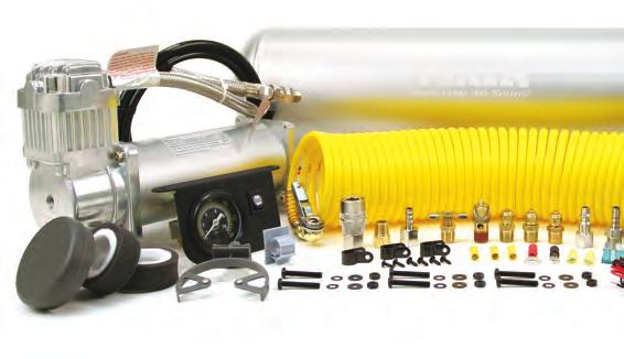
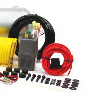
2 Thank you for purchasing this complete, self-contained onboard air system. Contained in one package, you ll find everything you ll need to install a high performance, onboard air source for your vehicle. Please follow these instructions to install your new system. OBA Components: Gallon, 6 port VIAIR Air Tank 1-450C model VIAIR compressor 1-36-ft. Length of 1/4 Air Line (for accessory and gauge installation) 1-35-foot Coil Hose with clip-on chuck (Please check to make sure that you have four labeled packages in your Onboard Air System kit. Each package contains the parts needed for specific areas of onboard air installation, and may contain smaller bags within each package labeled for specific use.)
3 REDUCER REDUCER CONSTANT DUTY ONBOARD AIR SYSTEM PARTS PACKAGES Package #1 Air Tank Installation: Package #3 Pressure Switch & Reducer: A B C D E Z AA F G H I J A. Mounting Bolts (4pcs) B. Flat Washers (8pcs) C. Locking Washers (4pcs) D. Nuts (4pcs) E. Rubber Tank Mount Bushings (6pcs) F. 1/4 NPT Drain Cock (1pc) G. 1/4 NPT 175 PSI Safety Valve (1pc) H. 1/4 NPT Compression Fitting (3pcs) I. 1/4 NPT F Quick Connect Coupler (1pc) J. 1/4 NPT F Quick Connect Stud (1pc) REDUCER REDUCER Y. Pressure Switch with Relay - (110 PSI on, 145 PSI off) (1pc) AA. Reducer (1/8 NPT F to 1/4 NPT M) (1pc) Package #4 Gauge Panel Installation: BB CC DD EE FF GG REDUCER HH II JJ DUCER Package #2 Compressor Installation: K L M N O P Q R S T V U W X Y BB. Dash Panel Gauge with ON/OFF Switch (1pc) CC. Mounting Bolts (2pcs) DD. Flat Washers (4pcs) EE. Locking Washers (2pcs) FF. Nuts (2pcs) GG. Push-on Female Terminals (2pcs) HH. 12-gauge Ring Terminal (1pc) II. 12-gauge Butt Connectors (2pcs) JJ. Self-tapping Screw (1pc) Z AA K. Mounting Bolts (4pcs) L. Flat Washers (8pcs) M. Locking Washers (4pcs) N. Nuts (4pcs) O. Remote Mount Air Filter Assembly (1pc) P. Remote Mount Air Filter Fittings for Compressor and Air Filters (2pcs) Q. 2-pack of Replacement Air Filters (1pc) R. Leader Hose Bracket Clip (1pc) S. Air line for Remote Mounting Air Filter (1pc) T. 4-inch Strip of continuous Grommet Material (1pc) U. Fuse Holder & 20 ft. 12 Gauge Wire (1pc) V. 30-amp Fuse (1pc) W. 12-gauge Ring Terminal (1pc) X. 12-gauge Butt Connector (1pc) Y. Self-tapping Screw (1pc) Z. Screws (6pcs) AA. Air Line Clips (3pcs)
4 2.5 GALLON AIR TANK & PLUMBING (USE CONTENTS OF PARTS PACKAGE #1) Your 2.5 Gallon air tank comes with six 1/4 NPT port openings to allow installation in many configurations on your vehicle. To ensure safe and trouble-free use of your air tank, we strongly recommend that you install the supplied drain cock and a safety pressure relief valve. (See Figure 1) Dash Panel Gauge Safety Valve Plumbing Diagram: (Figure 1) Pressure Switch with Relay Compression Fitting 2.5 Gallon Tank Reducer Leader Hose From Compressor Drain Cock Compression Fitting Quick Connect Couplers Tank Fittings: delman Install the supplied compression fittings and/or quick connect fitting for the air tank in areas where they are most appropriate for your installation using thread sealant. Make sure that the safety valve is installed in the top most position on the tank, and that the drain cock is installed in the lowest position on the tank if the tank is to be installed in any other position than upright on the tank s mounting legs. Be sure that all fittings are accessible later in the installation process since you will have to plumb air lines to each fitting as needed to utilize the air tank. Mounting the Tank: We have included 6 pieces of rubber bushings in your tank mounting hardware. You have the option of using two layers of rubber bushings on one of your tank legs to slightly tilt tank toward the drain cock to improve drainage. Use the provided longer bolts, and corresponding washers, and nuts to mount the tank to a suitable chassis or body point on your vehicle. IMPORTANT: - Tank is rated for 150 PSI maximum working pressure. - Tank is NOT to be used as a breathing device. - Bleed pressure from tank before servicing or adding attachments. - Use only attachments or tools rated for 150 PSI working pressure or less. CAUTION! DO NOT PRESSURIZE YOUR TANK UNTIL YOU HAVE INSTALLED ALL NECESSARY PORT FITTINGS AND ACCESSORIES. - Apply sealant to threads of fittings prior to assembly and tighten each part with a wrench. - Do not over tighten if your port fittings are made from brass, since brass threads can be stripped. - Always release air from tank before servicing. WARNING: FAILURE TO DRAIN TANK AND REMOVE CONDENSATION WILL CAUSE TANK TO RUST PREMATURELY. - To remove accumulated condensation inside the tank, bleed pressure from tank until pressure is approximately 5-20 PSI using drain cock - Drain tank by opening the drain cock drain valve and close after draining tank. - If drain cock valve is plugged, release all air pressure from tank, remove drain valve and clean, then reinstall. IMPORTANT: Please observe air tank s Date of Manufacture (stamped on tank leg). Replace air tank 2 to 5 years from date air tank was first used, or use the date of manufacture as reference. Adhering to air tank draining guidelines will prolong the life of your air tank. PLEASE NOTE: RUSTED TANKS CAN FAIL CAUSING EXPLOSIONS OR FATAL INJURIES. Discard tank immediately if tank is rusted. Coil Hose SAFETY VALVE: When using a safety pressure relief valve, point the safety pressure relief valve away from your body when releasing air. Use the pull ring on the safety relief valve to vent pressure from the tank before servicing.
5 450C AIR COMPRESSOR INSTALLATION (USE CONTENTS OF PARTS PACKAGE #2) Your Constant Duty Onboard Air System comes complete with a 450C, 100% duty cycle compressor. Please follow the installation instructions that follow to enjoy the best use of your onboard air system. CAUTION - To reduce risk of electrical shock or electrocution: - Do not disassemble the compressor. Do not attempt repairs or modifications. Refer to qualified service agencies for all service and repairs. - Do not use this product in an area where it can fall or be pulled into water or liquids. - Do not reach for this product if it has fallen into liquid. - Use this compressor with 12-volt DC systems only. - This product should never be left unattended during use. Guidelines for Selecting Mounting Location: The selection of proper mounting location for your air compressor will help ensure a long and trouble free compressor service life. Please pay close attention to the following: - Select a FLAT, UPRIGHT & SECURE LOCATION where the compressor can be mounted. - To maximize air compressor performance, locate compressor as CLOSE TO THE BATTERY as possible so that length of positive lead wire required is at a minimum. - Choose mounting location that is as cool as possible and away from heat sources. - This compressor is moisture & dust resistant, but NOT WATERPROOF or DUSTPROOF. Do not mount compressor in locations where the unit is likely to come in contact with water or excessive dirt. - For compressor with remote filter mounting, select compressor s mounting location where air line can be routed from compressor air inlet to remote inlet air filter. Make sure that the remote inlet air filter is located in a dry location, away from water. - You will also want to select a compressor mounting location where the leader hose bracket can be mounted to secure the leader hose. - If it is necessary to mount the air compressor further from the battery, such as inside your vehicle or in the bed of your pickup, use a minimum 8 AWG positive lead wire for remote installation. - Do not mount compressor near areas where flammable liquids are stored. - Use thread sealant for proper fitting installation. Thread tape is not recommended. Properly sealed, recommended torque for 1/4 and 3/8 is 16~18 ft. lbs. Recommended torque for 1/8 is 10~11 ft. lbs. 450C Compressor Wiring: (See Figure 2) 1. Disconnect ground cable from vehicle s battery. 2. Temporarily position the air compressor in the location where it will be mounted. 3. Route ground wire to the negative post of the battery or to an appropriate grounding point and cut ground wire to length as needed. 4. Mount the 450C air compressor with the four sets of 13/64 (5 mm) bolts, nuts, washers, and locking washers provided. Use of thread locker is recommended. 5. NOTE: For Remote Inlet Air Filter Installation, refer to Remote Inlet Air Filter Installation Instructions included in the Remote Inlet Air Filter Pack. 6. This air compressor comes with a heavy duty heat resistant stainless steel braided leader hose with 1/4 fittings. This leader hose is designed to prolong the life of your air line. Do not remove this leader hose from air compressor. 7. IMPORTANT: Please note; the leader hose that came with your compressor has a built-in inline check valve preinstalled. Do not remove inline check valve from leader hose. 8. Select a proper location to mount leader hose with hose bracket provided. Avoid locations where leader hose may become tangled with wires and other hoses. 9. To mount hose bracket, drill holes with 3/16 drill bit and push self anchoring hose bracket pin into hole. Route leader hose through hose bracket and secure hose by pressing bracket clamp into locked position. 10. To remove hose from the hose bracket, simply press down on the hose clamp release tab to release bracket clamp. 11. Connect compressor s positive lead wire to the appropriate lead of your pressure switch with relay. 12. Make sure that your compressor setup is properly fused. The 450C pulls approximately 23 amps of power. 13. Always locate fuse as close as possible to power source. 14. Before connecting to power source, check to make sure that all connections are made properly. 15. Connect and test compressor system by running the compressor for a short time to build up pressure in your air tank. 16. Once air pressure reaches preset cut out pressure of your pressure switch, the compressor will shut off. Inspect all air line connections for leaks with soap and water solution. If a leak is detected, the air line may not be cut squarely or pushed all the way in. Tighten connections if needed.
6 450C OPERATING INSTRUCTIONS CONSTANT DUTY ONBOARD AIR SYSTEM IMPORTANT: The 450C has a maximum working pressure of 150 PSI and is capable of 100% duty cycle. Always operate the compressor at or below the MAXIMUM PRESSURE RATING of the compressor. Operation exceeding maximum pressure ratings and or duty cycle will result in damage to air compressor. 1. Your air compressor is equipped with an AUTOMATIC THERMAL OVERLOAD PROTECTOR. This feature will protect the air compressor from overheating and causing permanent damage to your air compressor. The thermal overload protector will automatically cut off power to your air compressor should the internal operating temperature of the air compressor rise above safe levels during excessive use. 2. Should your air compressor automatically shut off during use, turn power to the system off. The automatic thermal overload protector will automatically reset when internal temperature of the air compressor drops below safe levels. After allowing air compressor to cool off for about 30 minutes, you can safely resume use of the air compressor by turning on the system. 3. To prevent discharge of your battery and to provide peak performance, it is recommended that you keep the engine running while the air compressor is in use. 4. ONLY OPERATE THE AIR COMPRESSOR IN WELL-VENTILATED AREAS. 450C Compressor Maintenance & Repairs: 1. Periodically check all electrical and fitting connections. Clean and tighten as needed. 2. Periodically check all mounting screws. Tighten as needed. 3. Replace air filter element periodically. Replacement frequency depends on operating frequency and operating environment. For frequent use in dusty environment, you should replace air filter element more often. 4. Regularly clean dust and dirt from compressor. 5. Your air compressor is equipped with permanently lubricated, maintenance-free motor. Never lubricate compressor. 6. Repairs should be performed by Manufacturer or Manufacturer s Authorized Service Agencies only. CAUTION: Never touch the air compressor or fittings connected to the air compressor with bare hands during or immediately after use. Leader hose and fittings will become very HOT during and after use. 450C Compressor Installation Tips: 1. Always use the remote intake filter option when possible. This will extend the service life of your compressor. 2. If noise reduction from vibration is desired, using the remote mount option for the inlet filter can reduce operation noise by up to 25%. 3. Always mount the compressor at a point higher than the inlet port of the tank. This will keep moisture from being able to seep back to the tank. 4. When mounting the compressor, use a paint pen on the rubber isolators and cover the side to go against the chassis or mounting location. Then, simply stamp the compressor against the chassis to make an imprint of exactly where to drill the mounting holes for the compressor. PRESSURE SWITCH WITH RELAY INSTALLATION (USE CONTENTS OF PARTS PACKAGE #3) Your VIAIR Constant Duty Onboard Air System comes complete with a pressure switch with relay that will turn on the compressor at 110 PSI, and off at 145 PSI. The pressure switch has a 1/8 NPT inlet at the bottom that will need to have the supplied 1/8 female to 1/4 male reducer fitting installed (using thread sealant) to allow it to be plumbed directly to your air tank. Pressure Switch with Relay Installation Tips: 1. Never install your pressure switch in direct line from the inlet port coming from the compressor. Tank pressure can be misread by the pressure switch. Mount the pressure switch on the tank where it receives reading from deflected air. 2. Never use a pressure switch that is rated beyond your compressor s rated maximum working pressure (150 PSI). 3. Replace with Pressure Switch with Relay P/N if the pressure switch fails.
7 DASH PANEL GAUGE INSTALLATION (USE CONTENTS OF PARTS PACKAGE #4) Your VIAIR Constant Duty Onboard Air System comes complete with a Dash Panel Gauge to monitor the pressure of your 2.5 gallon VIAIR air tank. Additionally, the Dash Panel Gauge has an ON/OFF switch preinstalled that will allow you to turn the system off by cutting power to the pressure switch with relay that you have already installed. We recommend that you install a master ON/OFF switch to allow the system to be turned off any time you anticipate leaving the vehicle parked for any length of time, and to avoid draining the vehicle s battery unnecessarily due to a slow air leak in your system. (see Figure 2) IMPORTANT: Each Dash Panel Gauge has been tested and calibrated. The air inlet on this gauge has a factory installed compression fitting. DO NOT attempt to tighten or loosen the body of this compression fitting. Any adjustments will cause the gauge to malfunction and void warranty. The Dash Panel Gauge included in this kit is rated for 150 PSI. Do not pressurize gauge over 150 PSI. 1. Select Mounting Location for Dash Panel Gauge Select a mounting location with a rigid mounting surface such as the bottom edge of the dashboard. Use the gauge mounting panel as a template; mark off two mounting points to be drilled. Carefully drill two 13/64 diameter holes as marked. Do not mount Dash Panel Gauge at this time. 2. Air Line Connection to Dash Panel Gauge Remove only the collar of the compression fitting from the back of the Dash Panel Gauge. Do not loosen or tighten the body of the compression fitting, which is permanently affixed to the air inlet of the gauge. Insert air line tubing through this collar, and then push air line tubing onto the barb of the compression fitting until the air line completely covers the barb. Tighten collar onto the body of the compression fitting with a wrench. 3. Routing Air Line to Air Source Route the air line tubing on the Dash Panel Gauge to the air source. Do not cut air line yet. In some cases a hole may need to be drilled to enable the air line to pass through to the air source. Make sure that the air line tubing is protected from any sharp edges of the drilled hole using grommet strip supplied. Connect to the tank using the 1/4 compression fitting supplied. Installation Tips: - When cutting air line tubing, always cut as squarely as possible. Use a hose cutter or razor blade. - When routing air line tubing, always remember to avoid sharp edges, heat sources and tight bends. (Air line must be routed at least 12 inches from exhaust systems & other heat sources.) IMPORTANT - Drilling through firewall: Always be sure of what is on the other side of the firewall before drilling. Take care not to damage your vehicle s electronic systems or components. 4. Wiring the ON/OFF Switch Attach one of the two remaining female terminal connectors to the wire that was routed from the pressure switch trigger wire (Small Red Wire on pressure switch with relay). There are two male spade connectors on the back of the ON/OFF switch. Connect this female terminal connector to one of the male spade connector on the ON/OFF switch. Next, attach appropriate size ring terminal provided in the kit to the end of the wire with the Inline Fuse. (The ring terminal should be about 12 from the inline fuse.) This wire is referred to as the power wire. Temporarily position the ring terminal at the power source and route power wire to the dash panel gauge, measure and cut to appropriate length. (If additional wire is necessary, use 16 AWG wire.) Attach the remaining female terminal connector to end of power wire, and connect to male spade connector on the ON/OFF switch. (Note: Do not connect gauge to power source at this time.)
8 DASH PANEL GAUGE INSTALLATION (CONT D) 5. Wiring the Dash Panel Gauge for Illumination There are two wires, one red and one black connected to the light bulb of the gauge. Connect the red wire to a suitable fused dash panel circuit. Use the quick splice connector included in the kit for wire connections. The black wire is to be connected to a suitable ground source. 6. Mounting the Dash Panel Gauge With all electrical and air line tubing routed and connected properly, mount the dash panel gauge using the two 13/64 nuts, bolts, and washers included with the Dash Panel Gauge. Make sure that no electrical wires or air line can be contacted by vehicle pedal operation, or by use of any safety equipment. Use provided zip ties to secure air line and electrical wiring. 7. Connect to Power Source Before connecting the power wire to a power source, check to make sure that the ON/OFF switch on the dash panel gauge is in the OFF position. Connect the ring terminal of the power wire to power source. (This is the wire described in Step 4, which is connected to the ON/OFF switch of the dash panel gauge.) 8. Testing Your Onboard Air System Your Onboard Air System installation is now complete. Run the compressor to build pressure in the air tank. When air pressure reaches the pressure switch cut out pressure, the compressor will shut off. Inspect all air line connections for leaks with soap and water solution and spray with a spray bottle onto connections to check for leaks. If leaks are detected, air line may not be cut squarely or pushed all the way in. Fix connections as needed. Periodically check your system s fitting in this manner should your compressor turn on more often than normal without frequent air use.
9 TROUBLESHOOTING GUIDE: PROBLEM Tank pressure drops when compressor (s) shut off POSSIBLE CAUSE(S) 1. Loose drain cock 2. Check valve leaking 3. Loose connections CORRECTIVE ACTION 1. Tighten drain cock 2. Replace check valve or compressor(s) 3. Check all connections with soap and water solution and tighten Compressor runs continuously and air flow lower than normal 1. Excessive air usage 2. Loose connections 3. Worn piston ring or inlet valve 4. Clogged air filter element 1. Decrease air usage 2. Check all connections with soap and water solution and tighten 3. Repair or replace compressor 4. Replace air filter element Compressor runs continuously causing safety valve (if equipped) to open 1. Bad pressure switch 2. Defective safety valve 1. Replace pressure switch 2. Replace safety valve Excessive moisture in discharge Compressor will not run Thermal overload protector cuts out repeatedly Excessive knocking or rattling 1. Excessive water in air tank 2. High humidity 1. No power, or power switch in OFF position 2. Blown fuse 3. Motor overheats 4. Faulty pressure switch 1. Lack of proper ventilation or ambient temperature too high 2. Compressor valves failed 1. Loose mounting bolts 2. Worn bearing on eccentric or motor shaft 3. Cylinder or piston ring is worn 1. Drain tank, tilt tank to drain Drain tank more frequently 2. Move compressor to area with less humidity, or use air line filter 1. Make sure compressor switch is ON 2. Disconnect compressors from power source, replace fuse (Refer to Specifications section for correct fuse amperage) 3. Let compressors cool off for about 30 Minutes to allow thermal overload switch reset 4. Replace pressure switch 1. Move compressor to well ventilated area, or area with lower ambient temperature 2. Repair or replace compressor 1. Tighten mounting bolts 2. Repair or replace compressor 3. Repair or replace compressor CAUTION: NEVER DISASSEMBLE COMPRESSOR WHILE COMPRESSOR IS PRESSURIZED.
10 COMPRESSOR APPLICATION GUIDE CONSTANT DUTY ONBOARD AIR SYSTEM To ensure that you get the highest level of satisfaction from your compressor performance, refer to information below: VIAIR COMPRESSOR REFERENCE CHART COMPRESSOR SERIES DUTY CYCLE MAX. WORKING PRESSURE ( F) 090 SERIES 9% 120 PSI 092 SERIES 9% 120 PSI 095 SERIES 9% 120 PSI 097 SERIES 10% 130 PSI 098 SERIES 10% 130 PSI 100 SERIES 15% 130 PSI 250 IG SERIES 100% 150 PSI 275 SERIES 25% 150 PSI 280 SERIES 30% 150 PSI 325 SERIES 33% 150 PSI 330 IG SERIES 100% 150 PSI 350 SERIES 100% 150 PSI 380 SERIES 100% 200 PSI *55% 400 SERIES 33% 150 PSI 420 SERIES 33% 150 PSI 444 SERIES 100% 200 PSI *50% 450 SERIES 100% 150 PSI 450 IG SERIES 100% 150 PSI 460 SERIES 100% 150 PSI 480 SERIES 100% 200 PSI *50% *Duty Cycle at 200 PSI and 72 F. ABOUT COMPRESSOR DUTY CYCLE: Duty cycle refers to the amount of time a compressor can be operated in a given time period at 100 PSI, and a standard ambient temperature of 72 F. It is commonly expressed in percentage format: Compressor on time (on time + off time) = Duty Cycle %. ONE-HOUR DUTY CYCLE MINUTES ON / ( F) MINUTES OFF 9% 5 Min. On / 55 Min. Off 10% 6 Min. On / 54 Min. Off 15% 9 Min. On / 51 Min. Off 20% 12 Min. On / 48 Min. Off 25% 15 Min. On / 45 Min. Off 30% 18 Min. On / 42 Min. Off 33% 20 Min. On / 40 Min. Off 50% 30 Min. On / 30 Min. Off 100% 1 Hour Run Time NOTE: All compressors, regardless of rated duty cycle, require sufficient rest time in between cycles to allow for partial or complete heat dissipation. Heat dissipation rates may vary depending on ambient temperatures and operating conditions. ABOUT RATED WORKING PRESSURE: To ensure trouble free service life of your compressor, always operate compressor within rated working pressure of the compressor. Never use a pressure switch with a higher cut-off pressure than compressor s rated working pressure.
11 AMERICAN WIRE GAUGE GUIDE 12-VOLT: Amp Draw Length of wire from battery to compressor (in feet) Wiring Diagram: (Figure 2) To Lamp Circuit Dash Panel To Keyed Power Source White Black Small Red Large Red Fuse + - Battery
12 LIMITED WARRANTY: VIAIR Corporation warrants this product, when properly installed and under normal conditions of use, to be free from defects in workmanship and materials for a period of one year from its original date of purchase. To receive warranty service or repair, please contact VIAIR Corporation. Returns should be made within one year of the date of purchase, after a Return Goods Authorization (RGA) number has been assigned by VIAIR Corporation. To obtain RGA, fax a copy of your receipt to (949) For complete warranty details, please visit: warranty PLEASE NOTE: THIS WARRANTY COVERS PRODUCT DEFECTS ONLY; IT DOES NOT COVER INCIDENTAL OR CONSEQUENTIAL DAMAGES AS RESULT OF MISUSE OR ABUSE. This Manual is proprietary to VIAIR Corporation and no ownership rights are hereby transferred. No part of the Manual shall be used, reproduced, translated, converted, adapted, stored in a retrieval system, communicated or transmitted by any means, for any commercial purpose, including without limitation, sale, resale, license, rental or lease, without the prior express written consent of VIAIR. VIAIR does not make any representations, warranties or guarantees, express or implied, as to the accuracy or completeness of the Manual. Users must be aware that updates and amendments will be made from time to time to the Manual. It is the user s responsibility to determine whether there have been any such updates or amendments. Neither VIAIR nor any of its directors, officers, employees or agents shall be liable in contract, tort or in any other manner whatsoever to any person for any loss, damage, injury, liability, cost or expense of any nature, including without limitation incidental, special, direct or consequential damages arising out of or in connection with the use of the Manual. 15 EDELMAN IRVINE, CA TEL: (949) FAX: (949)
HEAVY DUTY ONBOARD AIR SYSTEM
 HEAVY DUTY ONBOARD AIR SYSTEM PART NO. 10005 IMPORTANT: It is essential that you and any other operator of this product read and understand the contents of this manual before installing and using this
HEAVY DUTY ONBOARD AIR SYSTEM PART NO
 IMPORTANT: It is essential that you and any other operator of this product read and understand the contents of this manual before installing and using this product. SAVE THIS MANUAL FOR FUTURE REFERENCE
MEDIUM DUTY ONBOARD AIR SYSTEM
 MEDIUM DUTY ONBOARD AIR SYSTEM PART NO. 10003 IMPORTANT: It is essential that you and any other operator of this product read and understand the contents of this manual before installing and using this
MODEL NUMBER: MEDIUM DUTY ONBOARD AIR SYSTEM
 MODEL NUMBER: 10003 MEDIUM DUTY ONBOARD AIR SYSTEM IMPORTANT: It is essential that you and any other operator of this product read and understand the contents of this manual before installing and using
HEAVY DUTY ONBOARD AIR SYSTEM
 Thank you for purchasing this complete, self-contained onboard air system. Contained in one package, you ll find everything you ll need to install a high performance, onboard air source for your vehicle.
ONBOARD AIR HOOKUP KIT
 ONBOARD AIR HOOKUP KIT PART NO. 20052 (30 amp - 110PSI on, 150PSI off) PART NO. 20053 (30 amp - 85PSI on, 105 PSI off) PART NO. 20055 (30 amp - 90 PSI on, 120 PSI off) IMPORTANT: It is essential that you
40041 Heavy Duty ADA System with Booster Bracket for JK Heavy Duty ADA System with Booster Bracket for 2012 to Current JK
 40041 Heavy Duty ADA System with Booster Bracket for 2007-2011 JK 40044 Heavy Duty ADA System with Booster Bracket for 2012 to Current JK 40049 Heavy Duty ADA System Universal for all vehicles (booster
Model 6275RC 50% Duty Cycle Compressor
 Model 6275RC 50% Duty Cycle Compressor IMPORTANT: It is essential that you and any other operator of this product read and understand the contents of this manual before installing and using this product.
150 PSI ILLUMINATED DASH PANEL GAUGE KIT
 150 PSI ILLUMINATED DASH PANEL GAUGE KIT PART NO. 10061 (For Use with 20/30 Amp Systems) PART NO. 20062 (For Use with 30/40 Amp Systems) IMPORTANT: It is essential that you and any other operator of this
INSTALLATION AND USER MANUAL
 INSTALLATION AND USER MANUAL SDKIT-730 & SDKIT-734 100% Bolt-On 150 PSI Train Horn System for 2011-2015 F-250 & F-350 Super Duty P/N SDKIT-730 P/N SDKIT-734 Thank you for purchasing a Kleinn Air Horns
HORNBLASTERSTM. OutLaw 232 TM. Locomotive Air Horn System Manual
 HORNBLASTERSTM OutLaw 232 TM Locomotive Air Horn System Manual HornBlastersTM Outlaw 232 TM Locomotive Air Horn System Installation Guide Before Getting Started Read over the entire instruction guide before
HORNBLASTERS. Five Gallon Conductor s Special Installation Manual
 HORNBLASTERS Five Gallon Conductor s Special Installation Manual HornBlasters Five Gallon Conductor s Special Installation Guide Support Line: +1 (813) 783-8058 Fax Line: +1 (813) 783-2407 support@hornblasters.com
Xtreme Air Command. Step 1 Prepare the components. Step 2 Select a mounting location. Parts list
 2549 60 90 400 600 30 200 120 800 psi 1000 kpa PSI 0 150 Xtreme Air Command Installation instructions Congratulations on your purchase of a new Xtreme Air Command kit. This kit was designed to provide
Kit INSTALLATION GUIDE. 5 psi Low Pressure Sensor (Single Gauge)
") ª Kit 25592 5 psi Low Pressure Sensor (Single Gauge) MN-333 (131107) ECR 7119 INSTALLATION GUIDE For maximum effectiveness and safety, please read these instructions completely before proceeding with installation.
ª Kit 25592 5 psi Low Pressure Sensor (Single Gauge) MN-333 (131107) ECR 7119 INSTALLATION GUIDE For maximum effectiveness and safety, please read these instructions completely before proceeding with installation.
Service Guide JATCO Environmental Protection Tank Model J-7000
 Service Guide JATCO Environmental Protection Tank Model J-7000 Listed below are a series of steps to follow if the JATCO tank fails to dump properly. #1. Be sure there is an adequate supply of gas pressure
Kit psi Low Pressure Sensor (Dual Gauge)
") ª Kit 25812 5 psi Low Pressure Sensor (Dual Gauge) MN-337 (111107) ECR 7119 INSTALLATION GUIDE For maximum effectiveness and safety, please read these instructions completely before proceeding with installation.
ª Kit 25812 5 psi Low Pressure Sensor (Dual Gauge) MN-337 (111107) ECR 7119 INSTALLATION GUIDE For maximum effectiveness and safety, please read these instructions completely before proceeding with installation.
6L Oil-less Air Compressor 53103
 6L Oil-less Air Compressor 53103 Operating Instructions Please read and save these instructions before attempting to assemble, install, operate or maintain the product. Protect yourself and others by observing
INSTALLATION INSTRUCTIONS For Model 855 Wolo Express TM
 INSTALLATION INSTRUCTIONS For Model 855 Wolo Express TM 12-Volt Train Horn Your purchase of a WOLO EXPRESS TRAIN HORN is the choice that will complement your vehicle. Wolo s products are manufactured with
OUTLAW INSTALLATION MANUAL 232, 240, 244, 248
 OUTLAW INSTALLATION MANUAL 232, 240, 244, 248 WARNING: To ensure the longevity of your system, reading and following these instructions are recommended. Make sure to change filters and to drain the moisture
INSTALLATION AND USER MANUAL P/N JK-OBA
 INSTALLATION AND USER MANUAL P/N JK-OBA 100% Bolt-On On-Board Air system Thank you for purchasing a Kleinn Air Horns JK_OBA on board air system. Kleinn Train Horn Systems are the only 100% bolt-on train
6 Litre Oil-Less Air Compressor
 Operator s Manual 6 Litre Oil-Less Air Compressor WARNING! Before using this appliance, read the Operator s manual and follow all its safety rules and instructions. SPECIFICATION HWKAC1 1.1 kw / 1.5 HP
SHOCKER XL INSTALLATION MANUAL 232, 240, 244, 248
 SHOCKER XL INSTALLATION MANUAL 232, 240, 244, 248 WARNING: To ensure the longevity of your system, reading and following these instructions are recommended. Make sure to change filters and to drain the
350 S. St. Charles St. Jasper, In Ph Fax
 350 S. St. Charles St. Jasper, In. 47546 Ph. 812.482.2932 Fax 812.634.6632 www.ridetech.com Part # 30154700 Big Red Analog Compressor Kit Components: 2 31920020 Thomas compressor 1 31915100 5 gallon aluminum
Outlaw Installation Manual
 Outlaw Installation Manual 127CX & 228VX WARNING: To ensure the longevity of your system, reading and following these instructions are recommended. Make sure to change filters and to drain the moisture
Portable Oil Free Silent Series Compressor Operating Instructions
 Portable Oil Free Silent Series Compressor Operating Instructions NOTICE Carefully read this instruction manual before attempting to operate this compressor. MODEL # SERIAL # 1-800-551-2406 www.eaglecompressor.com
Shocker XL Installation Manual
 Shocker XL Installation Manual 232, 240, 244, 248 WARNING: To ensure the longevity of your system, reading and following these instructions are recommended. Make sure to change filters and to drain the
I. Assembling the Air Spring
 B F H G D FRONT I Assembling the Air Spring 1 Install 90 degree air swivel fitting (D) to the top of the bellow This fitting is precoated with sealant Using an open-end wrench, tighten 1 and 1 /2 turns
HORNBLASTERS. Shocker Classic 228VX Installation Manual
 Shocker Classic 228VX Installation Manual HornBlasters Shocker Classic 228VX Train Horn Kit Installation Guide Support Line: +1 (877) 209-8179 Fax Line: +1 (813) 783-2407 support@hornblasters.com www.hornblasters.com/support
HP10134 & HP10135 KITS BASIC SIMULTANEOUS AIR SPRING ACTIVATION KIT
 HP10134 & HP10135 KITS BASIC SIMULTANEOUS AIR SPRING ACTIVATION KIT Thank you and congratulations on the purchase of a Pacbrake simultaneous air spring activation kit. This kit was designed to add in-cab
Part # Series RidePro 4 Way Compressor System 3 Gallon Tank Analog Gauges
 350 S. St. Charles St. Jasper, In. 47546 Ph. 812.482.2932 Fax 812.634.6632 www.ridetech.com Part # 30154000 4000 Series RidePro 4 Way Compressor System 3 Gallon Tank Analog Gauges Components: 1 31920020
Part # Mopar LX Level 1 Air Suspension System
 Part # 13040199 05-14 Mopar LX Level 1 Air Suspension System Front Components: 1 1304409 Front RQ ShockWave Kit for Stock Lower Arms Rear Components: 1 13044099 Rear CoolRide Kit 1 13040709 RQ Series Rear
Kit INSTALLATION GUIDE. 5 psi Low Pressure Sensor (Single Gauge)
") Kit 25592 5 psi Low Pressure Sensor (Single Gauge) MN-333 (141404) ECR 7953 INSTALLATION GUIDE For maximum effectiveness and safety, please read these instructions completely before proceeding with installation.
Kit 25592 5 psi Low Pressure Sensor (Single Gauge) MN-333 (141404) ECR 7953 INSTALLATION GUIDE For maximum effectiveness and safety, please read these instructions completely before proceeding with installation.
Air Commander Part No , with air Part No , without air
 EASYSTREET Air Commander Part No. 27325, with air Part No. 27332, without air www.airliftcompany.com Please read these instructions completely before proceeding with installation. The oil level in the
Kits and Single Gauge Analog Compressor Systems
 Kits 25850 and 25854 Single Gauge Analog Compressor Systems Kit #25850 with standard duty compressor Kit #25854 with heavy duty compressor MN-750 (061202) ECR 7259 INSTALLATION GUIDE For maximum effectiveness
SPECIFICATIONS Horsepower: 1.5 HP Running Maximum PSI: 125 PSI Tank Capacity: 15 Gallons CFM: 6 40 PSI 5 90 PSI
 15 GALLON AIR COMPRESSOR Model: 7678 DO NOT RETURN TO STORE Please call 800-348-5004 for parts and service CALIFORNIA PROPOSITION 65 WARNING: You can create dust when you cut, sand, drill or grind materials
Part # C-10 Level 1 Air Suspension System
 350 S. St. Charles St. Jasper, In. 47546 Part # 11330199 63-72 C-10 Level 1 Air Suspension System Front Components: 1 11331099 Front CoolRide Kit for Stock Lower Arms 1 11330509 RQ Series Front Shock Kit
ONBOARD AIR SYSTEM FOR ALL VEHICLES APPLICATIONS
 ONBOARD SYSTEM FOR ALL VEHICLES APPLICATIONS Thank you and congratulations on the purchase of a Pacbrake onboard air system. Please read the manual prior to starting to ensure you can complete the installation
Shocker XL Installation Manual
 Shocker XL Installation Manual 232, 240, 244, 248 WARNING: To ensure the longevity of your system, reading and following these instructions are recommended. Make sure to change filters and to drain the
HP10098 BASIC INDEPENDENT AIR SPRING ACTIVATION KIT
 HP10098 BASIC INDEPENDENT AIR SPRING ACTIVATION KIT Thank you and congratulations on the purchase of a Pacbrake basic independent air spring activation kit. Please read the entire installation manual prior
ARC4800L Big Red Compressor System
 350 S. St. Charles St. Jasper, In. 47546 Ph. 812.482.2932 Fax 812.634.6632 on the internet: www.ridetech.com ARC4800L Big Red Compressor System 2 ARC7000 ViAir 400C 150psi compressors 2 F9242 5 gallon
ARC4000e 4 wheel compressor system w / 4 way Ride Pro controller
 350 S. St. Charles St. Jasper, In. 47546 Ph. 812.482.2932 Fax 812.634.6632 on the internet: www.ridetech.com ARC4000e 4 wheel compressor system w / 4 way Ride Pro controller 1 ARC5001 Compressor 1 CON6000
Part # Galaxie Level 1 Complete Air Suspension System
 350 S. St. Charles St. Jasper, In. 47546 Ph. 812.482.2932 Fax 812.634.6632 www.ridetech.com Part # 12160199 60-64 Galaxie Level 1 Complete Air Suspension System Front Components: 1 12162409 Front RQ Series
Model: ACP-12 AUTO COMPRESSOR PUMP SYSTEM 12 VDC INSTALLATION & OPERATION MANUAL. Phone:
 INSTALLATION & OPERATION MANUAL Model: ACP-12 AUTO COMPRESSOR PUMP SYSTEM 12 VDC Manual Part # M-ACP12 Revised 10/27/08 KK 1 INTRODUCTION The Auto Compressor Pump system is a compact 12 VDC electric motor
INSTALLATION INSTRUCTIONS
 28 INSTALLATION INSTRUCTIONS SECTION - AIR SPRING SECTION 2 - AIR ACCESSORY 2-5 ! IMPORTANT PLEASE DON T HURT YOURSELF, YOUR KIT OR YOUR VEHICLE. TAKE A MINUTE TO READ THIS IMPORTANT INFORMATION. This
AIR CONTROL ACCESSORY KIT
 RAPID RESPONSE SYSTEM 2283 AIR CONTROL ACCESSORY KIT INSTALLATION INSTRUCTIONS Congratulations on your purchase of a new Air Control Accessory Kit. This kit was designed to provide inflation control of
Heavy Duty Air Command
 2097 / 2227 Heavy Duty Air Command INSTALLATION INSTRUCTIONS Congratulations on your purchase of a new Air Command kit. This kit was designed to provide inflation control of your air helper springs. This
A/C PRESSURE MONITOR INSTALLATION INSTRUCTIONS SYSTEM OPERATION GREEN INDICATOR LIGHT
 A/C PRESSURE MONITOR INSTALLATION INSTRUCTIONS Do not attempt to clean or inspect anything while the engine is running. Cleaning and inspection must be done by a certified mechanic. All A/C service must
8-GALLON AIR COMPRESSOR Owner s Manual
 8-GALLON AIR COMPRESSOR 207-1520 Owner s Manual PRODUCT SPECIFICATIONS Rating: 120 V, 60 Hz, Induction Amperes: 12 A Tank Size: 8U.S. gallons Air Delivery (CFM*)@0 PSI: 5.2 Air Delivery (CFM*)@90 PSI:.2
GMTRK1 BOLT-ON TRAIN HORN SYSTEM INSTALLATION INSTRUCTIONS. For GM & GMC Trucks & SUVS
 GMTRK1 BOLT-ON TRAIN HORN SYSTEM INSTALLATION INSTRUCTIONS For 2007-2017 GM & GMC Trucks & SUVS The GMTRK-1 System comes with a custom battery tray to hold the air compressor and air tank. The horns will
SUNC1200 / ITEM #40882 SUBMERSIBLE UTILITY PUMP OPERATIONS MANUAL
 SUNC1200 / ITEM #40882 SUBMERSIBLE UTILITY PUMP OPERATIONS MANUAL WWW.SUNRUNNERPOOL.COM Performance Model HP GPH of Water @ Total Feet Of Lift 0 ft. 5 ft. 10 ft. 15 ft. 20 ft. 25 ft. Max. Lift SUNC1200
Kit INSTALLATION GUIDE. 5 psi Low Pressure Sensor (Single Gauge)
") Kit 25592 5 psi Low Pressure Sensor (Single Gauge) MN-333 (131107) ECR 7119 INSTALLATION GUIDE For maximum effectiveness and safety, please read these instructions completely before proceeding with installation.
Kit 25592 5 psi Low Pressure Sensor (Single Gauge) MN-333 (131107) ECR 7119 INSTALLATION GUIDE For maximum effectiveness and safety, please read these instructions completely before proceeding with installation.
KIT No , and 80590
 KIT No. 80531, 80545 and 80590 by MN-354 (05603) ECR 5593 Please read these instructions completely before proceeding with installation Air Spring Kit Parts List Item Description Quantity A Air Spring
AT-38 On-Demand. For Driving Safety and Convenience. Installation & Operation Manual for AT-38OD Unit
 The Leader in Heated Washer Systems AT-38 On-Demand For Driving Safety and Convenience Installation & Operation Manual for AT-38OD Unit Our Warmest Congratulations! You are now the Owner of a Heated Washer
HORNBLASTERS. Nathan AirChime K5 Train Horn Kit Installation Manual
 HORNBLASTERS Nathan AirChime K5 Train Horn Kit Installation Manual HornBlasters K5 Train Horn Kit Installation Guide Support Line: +1 (813) 783-8058 Fax Line: +1 (813) 783-2407 support@hornblasters.com
Equipped with AEM Dryflow Filter No Oil Required! INSTALLATION INSTRUCTIONS PART NUMBER:
 Equipped with AEM Dryflow Filter No Oil Required! INSTALLATION INSTRUCTIONS PART NUMBER:21-8125 2011-2012 Ford F150 V8 5.0L * NOTE: Legal in California only for racing vehicles which may never be used
Kit INSTALLATION GUIDE. For maximum effectiveness and safety, please read these instructions completely before proceeding with installation.
 Kit 25801 MN-208 (121506) ECR 8243 INSTALLATION GUIDE For maximum effectiveness and safety, please read these instructions completely before proceeding with installation. Failure to read these instructions
AEROMOTIVE Part # Street Rod Fuel Pump System INSTALLATION INSTRUCTIONS
 AEROMOTIVE Part # 17201 Street Rod Fuel Pump System INSTALLATION INSTRUCTIONS CAUTION: Installation of this product requires detailed knowledge of automotive systems and repair procedures. We recommend
Please read these instructions completely before proceeding with installation. Read all maintenance guidelines on page 7 before operating the vehicle.
 MN-643 (02511) ECR 5461 Kit No. 39205 Please read these instructions completely before proceeding with installation Item P/N Description Quantity A 26391 Driver-Side Beam Assembly 1 B 26414 Passenger-Side
SHALLOW WELL JET PUMP
 SHALLOW WELL JET PUMP MODEL FJ05S 1/2 HP flintandwalling.com ATTACH YOUR RECEIPT HERE Serial Number Purchase Date 1 FW1642 B TABLE OF CONTENTS Product Specifications...2 Safety Information...2 Package
INSTALLATION INSTRUCTIONS
 2807 INSTALLATION INSTRUCTIONS SECTION - AIR SPRING SECTION 2 - AIR ACCESSORY -6 ! IMPORTANT PLEASE DON T HURT YOURSELF, YOUR KIT OR YOUR VEHICLE. TAKE A MINUTE TO READ THIS IMPORTANT INFORMATION. This
Introduction Important Safety Notice...2 Notation Explanation...2. Hardware List...4. Attaching the Compressor...4. Wiring the System...
 LifeSTYLE Kits 27665/27666 Cover illustration may not depict actual kit. MN-726 (02002) ECR 684 INSTALLATION GUIDE For maximum effectiveness and safety, please read these instructions completely before
Kit No Please read these instructions completely before proceeding with installation. Air Spring Kit Parts List. Bracket Attaching Hardware
 Kit No. 59532 MN-572 (021108) ECR 7136 Please read these instructions completely before proceeding with installation Air Spring Kit Parts List A Item Description Quantity A Air Sleeves 2 B Upper Brackets
STAR STOP SHALLOW WELL JET PUMP
 SHALLOW WELL JET PUMP MODEL SJ0S / HP STAR starwatersystems.com STOP Questions, problems, missing parts? Before returning to your retailer, call our customer service department at -800-7-0, 7:0 a.m. -
OWNER S MANUAL SELF-PRIMING PORTABLE UTILITY PUMP
 Model 54011-0 OWNER S MANUAL SELF-PRIMING PORTABLE UTILITY PUMP Questions, problems, missing parts? Before returning to the store call AQUAPRO Customer Service 8 a.m. - 5 p.m., EST, Monday-Friday 1-844-242-2475
ROUSH FUEL SYSTEM UPGRADE CURRENT FORD MUSTANG 5.0L
 ROUSH FUEL SYSTEM UPGRADE 2011- CURRENT FORD MUSTANG 5.0L P/N: 421602 (1313-FPVRKIT) Installation Instructions Before installing your ROUSH Performance Product(s), read through the entire installation
C44090 HP325 PACBRAKE COMPRESSOR CONVERSION
 C44090 HP325 PACBRAKE COMPRESSOR CONVERSION APPLICATIONS: DODGE 2003-2007 5.9L CUMMINS Compressor Replacement Instructions for C14030, C14045, C44030, C44045, C44049 & C44052 with Air Tank KIT CONTENTS
Kit psi Low Pressure Sensor (Dual Gauge)
") Kit 25812 5 psi Low Pressure Sensor (Dual Gauge) MN-337 (111107) ECR 7119 INSTALLATION GUIDE For maximum effectiveness and safety, please read these instructions completely before proceeding with installation.
Kit 25812 5 psi Low Pressure Sensor (Dual Gauge) MN-337 (111107) ECR 7119 INSTALLATION GUIDE For maximum effectiveness and safety, please read these instructions completely before proceeding with installation.
PRODUCT NUMBERING SYSTEM SERIES PHASE. 1: Single Phase 3: Three Phase
 TABLE OF CONTENTS Product Numbering System and Specifications... Safety... Receiving and Inspection... Installation... Electrical...6 Start-up...7 INTRODUCTION The compressor you have purchased is a combination
Manual Concentrate Management System
 Form 887 05/15 Manual Concentrate Management System with Automatic Flush INSTALLATION AND OPERATION MANUAL Unit Serial Number All quality FoamPro products are ruggedly designed, accurately machined, carefully
USER S MANUAL FOR F & Q. Submersible Sewage Pumps
 USER S MANUAL FOR F & Q Submersible Sewage Pumps 50WQ Series The F&Q pumps are carefully inspected and tested to ensure operating performance and safety. However, failure to follow the instructions and
SUNC3000 / Item #40885
 SUNC3000 / Item #40885 AUTOMATIC POOL COVER PUMP OPERATIONS MANUAL WWW.SUNRUNNERPOOL.COM 1 . Performance GPH of Water @ Total Feet Of Lift MODEL HP Max. Lift 0 ft. 5 ft. 10 ft. 15 ft. 20 ft. SUNC3000 1/3
Your Legal Fuel Tank Source.
 February 23, 2015 IS# 808 Page 1 of 13 THANK YOU FOR PURCHASING A TRANSFER FLOW 40 GALLON TOOLBOX REFUELING SYSTEM. PLEASE READ THE FOLLOWING PROCEDURES CAREFULLY BEFORE STARTING THE INSTALLATION. CAUTION:
69-74 VW Beetle IRS Rear Kit Part No
 www.airliftcompany.com 69-74 VW Beetle IRS Rear Kit Part No. 75615 MN-476 (01102) ECN 3455 Please read these instructions completely before proceeding with installation A C B E D AA F F ITEM QTY. PART
Kit No Please read these instructions completely before proceeding with installation. Air Spring Kit Parts List. Attaching Hardware
 Kit No. 57340 MN-431 (02409) NPR 4796 Please read these instructions completely before proceeding with installation by www.airliftcompany.com Air Spring Kit Parts List A B1 B2 Item Description Quantity
Light Duty Electronic Air Command
 2491 PSI BAR Light Duty Electronic Air Command INSTALLATION INSTRUCTIONS Congratulations on your purchase of a Light Duty Electronic Air Command kit. This kit was designed to provide inflation control
INFINITY-3 STROBE LED BAR INSTALLATION MANUAL 7700 SERIES
 INFINITY-3 STROBE LED BAR INSTALLATION MANUAL 7700 SERIES Your purchase of a Wolo warning light is the perfect choice to compliment your vehicle. Wolo s warning lights are manufactured with the finest
INFINITY-1 HALOGEN LIGHT BAR INSTALLATION MANUAL 7000 SERIES
 INFINITY-1 HALOGEN LIGHT BAR INSTALLATION MANUAL 7000 SERIES Your purchase of a Wolo warning light is the perfect choice to compliment your vehicle. Wolo s warning lights are manufactured with the finest
ULTRA QUIET & OIL FREE MP100LF MP120LF
 ULTRA QUIET & OIL FREE AIR COMPRESSOR MOTOR/PUMP OwnER'S MAnUAL MP100LF MP120LF WWW.CALIFORNIAAIRTOOLS.COM Customer Support 1-866-409-4581 TAbLe OF CONTeNTS INTROduCTION IntroductIon 2 IMPortant SaFety
OPERATING SERVICE MAINTENANCE MANUAL
 OPERATING SERVICE MAINTENANCE MANUAL ALL-STAR ROCKING PISTON COMPRESSOR AND VACUUM PUMP Registered by one or more of these standards agency ISO RoHS 9001 Compliant CE Read through carefully and understand
OWNER S MANUAL SUBMERSIBLE UTILITY PUMP
 Model 51101-0 OWNER S MANUAL SUBMERSIBLE UTILITY PUMP Questions, problems, missing parts? Before returning to the store call AQUAPRO Customer Service 8 a.m. - 5 p.m., EST, Monday-Friday 1-844-242-2475
SPECIFICATIONS: Tank Size: 80 gallons PUMP RPMs: 1050 CFM: 40PSI; 90 PSI Max Pressure: 150 PSI Thermal overload protection
 5HP 80 GALLON TWO STAGE COMPRESSOR Models: 51866, 51870 CALIFORNIA PROPOSITION 65 WARNING: You can create dust when you cut, sand, drill or grind materials such as wood, paint, metal, concrete, cement,
USER S MANUAL FOR F & Q. Submersible Sewage Pumps
 USER S MANUAL FOR F & Q Submersible Sewage Pumps 100WQ Series The F&Q pumps are carefully inspected and tested to ensure operating performance and safety. However, failure to follow the instructions and
Tools Needed. I. Getting Started
 5 /16 ", 7 /16 ", 9 /16 " and 19mm open-end or box wrenches Crescent Wrench Ratchet with 9 /16 " and 1 /2 " deep well sockets 3 /8 " and 5 /16 " drill bits (very sharp) Heavy Duty Drill Torque Wrench Tools
HALLMARK INDUSTRIES INC
 Performance Part No. HP. CONVERTIBLE JET PUMP USER S MANUAL GPH of Water @ Total Discharge Pressure of 40 psi Max. Pressure Max suction (shallow well) Max Suction (deep well) Max GPM (@0 head) Max Discharge
Model A Turn Signal Kit Installation Guide
 Model A Turn Signal Kit Installation Guide Creative Connections, Inc. Consumer Hot Line: 888-471-LOGO 770-476-7322 In Atlanta, GA http://www.logolites.com P/N: 100-005/K 2008 Creative Connections, Inc.
Installation Instructions - ECS Tuning Vent Pod Vacuum/Boost Gauge Kit
 Installation Instructions - ECS Tuning Vent Pod Vacuum/Boost Gauge Kit This tutorial is provided as a courtesy by ECS Tuning. Part Number for Audi B6 A4 (2002-2004) Proper service and repair procedures
4" ENVIRONMENTAL E-SERIES PUMPS OWNER'S MANUAL. DANGER warns about hazards that will cause. WARNING warns about hazards that can cause
 4" ENVIRONMENTAL E-SERIES PUMPS OWNER'S MANUAL BEFORE INSTALLING PUMP, BE SURE TO READ THIS OWNER S MANUAL CAREFULLY. CAUTION Fill pump with water before starting or pump will be damaged. The motor on
Features and Benefits Wide Bottom: Translucent Bottle: 2 1/2 Gallon Bottle: Removable Bottle: Large cap: 15 Feet of Coiled Hose:
 12 Volt Battery Powered Sprayer This unit uses a lead acid battery. The charge capacity of the battery can be greatly diminished if fully discharged. Care should be given to charge the battery between
Fuel Pressure Regulator Kit PART# - RY12040-RRFPR-6S5
 APPLICATION(S): Yamaha FX-SHO, FZR & FZS Fuel Pressure Regulator Kit PART# - RY12040-RRFPR-6S5 We strongly recommend the use of a service manual to familiarize yourself with the various components and
Thank You. for purchasing an Edelbrock Nitrous Oxide Injection System. Please take the time to read and understand the following.
 Thank You. for purchasing an Edelbrock Nitrous Oxide Injection System. Nitrous Oxide injection is one of the most exciting performance enhancements for the dollar invested on the market today. With the
INSTALLATION INSTRUCTIONS
 INSTALLATION INSTRUCTIONS Thank you for purchasing ROLTECTM Electric Hopper Conversion. Agri-Cover, Inc. proudly manufactured this hardware using superior quality materials and workmanship. With proper
HexPro Series Low Profile Wrenches
 HexPro Series Low Profile Wrenches Operation and Maintenance Manual Model 2HP 4HP 8HP 14HP 30HP www.torquetoolsinc.com Use the HEXPRO Series Low Profile Wrenches Model 2HP 4HP 8HP 14HP 30HP to install
Equipped with AEM Dryflow Filter No Oil Required! INSTALLATION INSTRUCTIONS PART NUMBER: DS (Plastic Intake Tube)
") Equipped with AEM Dryflow Filter No Oil Required! INSTALLATION INSTRUCTIONS PART NUMBER:21-8126DS (Plastic Intake Tube) 2011-2014 Ford F150 V6 3.5L ECOBOOST C.A.R.B. E.O. D-670-19 AEM Induction Systems
Equipped with AEM Dryflow Filter No Oil Required! INSTALLATION INSTRUCTIONS PART NUMBER:21-8126DS (Plastic Intake Tube) 2011-2014 Ford F150 V6 3.5L ECOBOOST C.A.R.B. E.O. D-670-19 AEM Induction Systems
STYLE 9300 FLOW/PRESSURE METER INSTALLATION & OPERATING INSTRUCTIONS
 STYLE 9300 FLOW/PRESSURE METER INSTALLATION & OPERATING INSTRUCTIONS INTRODUCTION The Style 9300 Flow/Pressure Meter from Akron is designed to offer reliable and accurate service with an easy to install,
AUTOMATIC SUBMERSIBLE UTILITY PUMP
 AUTOMATIC SUBMERSIBLE UTILITY PUMP Zoeller is a registered trademark of Zoeller Co. All Rights Reserved. MODEL #1043-0006 Español p. 9 ATTACH YOUR RECEIPT HERE Serial Number Purchase Date Questions, problems,
GEN 3 LED LIGHT BAR INSTALLATION MANUAL Model 7840-A 44"
 GEN 3 LED LIGHT BAR INSTALLATION MANUAL Model 7840-A 44" Your purchase of a Wolo warning light bar is the perfect choice to compliment your vehicle. Wolo s warning lights are manufactured with the finest
This document describes:
 Thank you for purchasing this product from ERM. We appreciate your interest in our unique product line as we try to offer our customers an alternative to today s traditional products. This programmable
Model and Series 115 VAC INDUSTRIAL DIAPHRAGM PUMPS. PumpAgents.com - buy pumps and parts online INDUSTRIAL DIAPHRAGM PUMPS
 Model 31801 and 31800 Series 115 VAC INDUSTRIAL DIAPHRAGM PUMPS INDUSTRIAL DIAPHRAGM PUMPS FEATURES Run Dry Ability Self-Priming Thermal Overload Protected Motor Easy Installation Low Amp Draw Compact
11202 INSTALLATION INSTRUCTIONS
 11202 INSTALLATION INSTRUCTIONS WARNING! The fuel system may be under pressure. Do not open the fuel system until any pressure has been relieved. The enclosed Aeromotive fuel pump utilizes an o-ring sealed
WARNING: Do not use pumps for gasoline or highly flammable products! Do not use pumps for water based fluids, solvents or chemicals!
 50:1 Value Line Pneumatic Grease Pump Technical Brief 07/01/2010 No. 18710 201 Fits 35 lb. Pail Premium quality pneumatic pump used for 35 lb. Pail 1.Recommended Usage Grease pumps with a ratio of 50:1