Installation, Operation and Maintenance Manual
|
|
|
- Roland Howard
- 6 years ago
- Views:
Transcription


1 Installation, Operation and Maintenance Manual Technical Manual EH 1.2

2 General Information about valve sizing: Valves with a Full Port have an internal seat diameter that is the same as the nominal pipe size, i.e. a 1 inch pipe size valve with a full port has a 1 inch diameter seat. Valves with a Reduced Port have an internal seat diameter that is smaller than the nominal pipe size. The valve s flow coefficient, Cv, is a value that is determined by flow testing for each valve size. Full port valves will have a higher Cv than reduced port valves. The Cv rating for each valve is listed in the tables found in the valve catalog. The definition of Cv is the # of gallons of water that will flow through the valve with a 1 PSI pressure differential when the valve is open. The equations below can be used to determine: Flow Rate, given the Cv and P Cv, given the Flow Rate and P P, given the Flow Rate and Cv Cv = Valve s flow coefficient (dimensionless value) S = Specific Gravity (1.0 for air or water) T = Absolute Temperature in R ( R = F + 460) P 1 = Inlet Pressure in PSIG P = Pressure Differential in PSI across valve in the open position V = Specific Volume in Cubic Feet per Pound Page 2 of 8
3 Installation: Before installing the valve, make sure the operating pressure, service and electrical requirements are compatible with your installation. Never apply incompatible fluids or exceed the pressure and temperature rating of the valve. Valve should be installed and maintained by qualified personnel only. IMPORTANT: Before installing the valve, be sure the system is clean and free from debris that may become lodged inside the valve preventing proper operation. Valve Orientation: EH30, EH40 and EH50 valves are designed to operate using a horizontal inlet pipe with the outlet facing downwards and the solenoid on top. EH30 valves that are supplied with the Universal Mount option can be installed in any orientation. EH70 valves can be installed in any orientation. The arrow on the valve body indicates the direction of flow. Pipelines need to be properly supported to prevent strains on the valve body. IMPORTANT: To protect valve internals and ensure trouble free operation, install a suitable strainer or filter on the inlet side as close to the valve as possible. Follow manufacturer s recommendations for installation and maintenance. End Connections: Female Pipe Thread: The use of Teflon tape, or other appropriate thread sealant, on all pipe thread connections is recommended. Care must be taken to prevent excess tape from entering the valve. For EH70 valves, always use the hexagonal portion of the valve body casting when applying torque or clamping. Never apply torque or pressure to other areas of the valve. Welded End (EH70 valves only): It is recommended that any end connection requiring welding be performed with the valve internals removed from the valve body. Damage to the seals inside of the valve may occur if temperature rises above 400 F. If necessary, the body may be wrapped with a water soaked rag to help dissipate heat. Ensure that any slag or debris is not allowed to enter the valve. Flanged, Union or other type end connection: Always use appropriately rated, mating end connections when connecting to the valve. Any seals or gaskets should be made from materials compatible with the fluid or valve service. Electrical Connections: Wiring, conduit and conduit connections must comply with National and Local Electrical Codes, as appropriate. Solenoids that are rated as explosion-proof and are being installed in a hazardous atmosphere must have an explosion-proof, conduit isolation fitting installed no more than 1 inch from the solenoid s conduit connection. Page 3 of 8
4 The standard solenoid enclosure has a 1/2 FNPT conduit connection. The solenoid may be rotated 360 to facilitate wiring connections by loosening the top nut, rotating the solenoid to the desired position then re-tightening the top nut. Lead wires supplied with the solenoid are a minimum of 18 long. The wire gauge size is determined by the solenoid s power requirements and is a minimum of 18 AWG. The wire used to connect to the power source should be the same or heavier gauge wire size as the lead wires. Unless otherwise indicated, all solenoids are designed to operate at ± 10% of the nominal voltage. Check the valve nameplate for specific voltage and amperage requirements. Fuses or circuit breakers are recommended and should be sized according to the inrush amperage and holding amperage requirements of the solenoid (see nameplate or contact the factory, phone: , techsupport@clarkcooper.com). The solenoid should not be cycled continuously more than 4 times per minute, unless it has been designed for a high cycle rate. Wiring diagram: CAUTION: During normal operation, the solenoid can become hot. DO NOT touch solenoid during operation. Allow to cool before handling. IMPORTANT: After the valve has been installed, it is recommended to cycle the valve dry and under normal operating conditions to allow the seals to properly seat under pressure. Basic Information: Pilot Operated valves work by opening a small pilot orifice to relieve pressure above the main piston allowing it to open. Direct Operated valves pull directly on the piston to open the valve. EH30 and EH70 Series valves operate from zero PSI up to the rated pressure. EH40 and EH50 Series valves operate from a minimum pressure of 50 PSI and 100 PSI respectively up to the rated pressure. Note: Pilot orifices and internal bleed holes are relatively small and can become obstructed by particulates in the fluid. Therefore, it is important to run clean fluids through the valve. All EH Series valves are designed to operate with the fluid flowing in one direction. Fluid flows into the valve above the seat and out of the valve below the seat. The valve will not prevent fluid from flowing in the reverse direction, except for the EH50 Series valve equipped with the optional, integrated check valve which will prevent reverse flow. Page 4 of 8
5 Maintenance and Repairs: It is recommended to periodically inspect the valve to insure that it is operating properly. If the valve is not functioning properly, it can be returned to the factory for a complete failure analysis. Upon authorization, the valve will be restored to like new condition. The valve can also be repaired by qualified personnel in a properly equipped workshop. In many instances, the valve can be repaired while it is still installed in the pipeline. DANGER: NEVER ATTEMPT TO DIS-ASSEMBLE A VALVE THAT IS UNDER PRESSURE. THIS MAY RESULT IN SERIOUS INJURY AND/OR DEATH. These repair and maintenance instructions should be used as a guide. Many Clark-Cooper valves are customized for specific applications. Therefore, these instructions may not provide all the necessary information required to properly service all models. Solenoid Replacement (EH30, EH40, EH50 and EH70): 1. Disconnect the solenoid from the power supply. 2. Remove the top solenoid nut and washer. 3. Remove the solenoid and replace with new solenoid. 4. Replace washer and nut. 5. Position the conduit connection as necessary and tighten the nut. 6. Reconnect the power supply. Piston Assembly Replacement for EH30 valves: 1. Lock out pressure to the valve. The valve inlet and outlet MUST BE at atmospheric pressure (0 PSIG) prior to servicing the valve. 2. Disconnect the solenoid from the power supply. 3. Remove the top solenoid nut, washer and solenoid. 4. Remove the Bonnet Retainer using Spanner Wrench (Part # A ). 5. Lift the bonnet off the valve body and remove the piston assembly. 6. Install new piston assembly and replace the body/bonnet o-ring in the groove on the bottom of the bonnet. 7. Re-assemble the bonnet onto the valve body. 8. Screw the bonnet retainer into place and tighten using the spanner wrench. 9. Re-assemble the solenoid, washer and nut onto the bonnet. 10. Position the conduit connection as necessary and tighten the nut. 11. Reconnect the power supply. Page 5 of 8
 prior to servicing the valve. 2. Disconnect the solenoid from the power supply. 3. Remove the top solenoid nut, washer and solenoid.")
6 Cartridge Assembly Replacement for EH40 and EH50 valves: (EH50 valve illustrated below) 1. Lock out pressure to the valve. The valve inlet and outlet MUST BE at atmospheric pressure (0 PSIG) prior to servicing the valve. 2. Disconnect the solenoid from the power supply. 3. Remove the top solenoid nut, washer and solenoid. 4. Remove the Bonnet Retainer using Spanner Wrench (Part # A ). 5. Remove Cartridge Assembly and Cartridge Gasket. 6. Install new Cartridge Assembly and Gasket. 7. Screw the bonnet retainer into place and tighten using the spanner wrench. 8. Re-assemble the solenoid, washer and nut onto the bonnet. 9. Position the conduit connection as necessary and tighten the nut. 10. Reconnect the power supply. Page 6 of 8

7 Piston Assembly Replacement for EH70 valves: 1. Lock out pressure to the valve. The valve inlet and outlet MUST BE at atmospheric pressure (0 PSIG) prior to servicing the valve. 2. Disconnect the solenoid from the power supply. 3. Remove the top solenoid nut, washer and solenoid. 4. Remove the Body/Bonnet bolts. 5. Lift the bonnet off the valve body and remove the piston assembly. 6. Install new piston assembly and replace the body/bonnet gasket in the top of the valve body. 7. Re-assemble the bonnet onto the valve body. 8. Tighten the body/bonnet bolts. 9. Re-assemble the solenoid, washer and nut onto the bonnet. 10. Position the conduit connection as necessary and tighten the nut. 11. Reconnect the power supply. Page 7 of 8
8 Page 8 of 8
CIRCLE SEAL CONTROLS
 CIRCLE SEAL CONTROLS ATKOMATIC SOLENOID VALVES INSTALLATION, MAINTENANCE, AND OPERATION INSTRUCTIONS 13000 SERIES Stainless, Normally Closed, Direct Lift, 3-Way Valve Installation Instructions WARNING:
CIRCLE SEAL CONTROLS
 CIRCLE SEAL CONTROLS ATKOMATIC SOLENOID VALVES INSTALLATION, MAINTENANCE, AND OPERATION INSTRUCTIONS 3000 SERIES Bronze, Normally Closed, Direct Lift Installation Instructions WARNING: These instructions
Product Manual. EX40, Version Last Updated: 11/7/16. Product Description:
 Product Manual EX40, Version 2016.1 Last Updated: 11/7/16 Product Description: The EX40 Series encompasses 2-way piloted solenoid valves with a maximum allowable inlet pressure of 15,000 psi [103.4 MPa].
ATEX/IECEx Coil Manual Type 200 and 300 Series Coils for EH70 Series Solenoid Valves Issue , Released December 13, 2017
 ATEX/IECEx Coil Manual Type 200 and 300 Series Coils for EH70 Series Solenoid Valves Issue 2017.1, Released December 13, 2017 Clark Cooper A Division of Magnatrol Valve Corp. 941 Hamilton avenue Roebling,
High Pressure Solenoid Valves
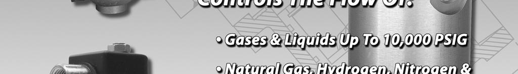
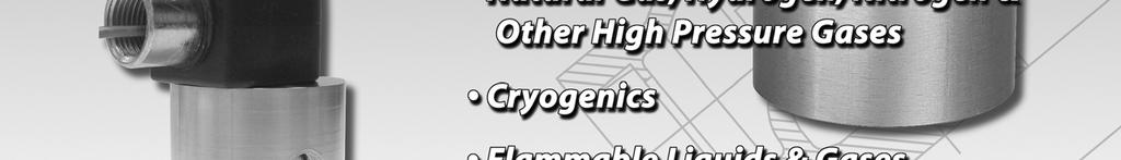
 High Pressure Solenoid Valves Available for Quick Delivery Controls the flow of Gases & Liquids up to 15,000 PSIG Natural Gas, Hydrogen & other High Pressure Gases High Pressure Cryogenics Flammable Liquids
INSTALLATION/OPERATION/MAINTENANCE INSTRUCTIONS FOR ARCHON MODELS WD2010L, WD2010, WD2010H WASHDOWN STATIONS. ARCHON Industries, Inc.
 ARCHON Industries, Inc. Washdown Stations Models WD2010L, WD2010, WD2010H Installation / Operation / Maintenance Instructions 1 This manual has been prepared as an aid and guide for personnel involved
2001 SERIES CRYOGENIC BAR STOCK BODY VALVES
 12501 Telecom Drive, Tampa, FL 33637 Ph: (813) 978-1000 Fax: (813) 977-3329 www.cpc-cryolab.com INSTALLATION, OPERATING, AND MAINTENANCE INSTRUCTIONS 17/4.5.2 Rev. 0 2001 SERIES CRYOGENIC BAR STOCK BODY
EH50 Product Manual Version
 EH50 Product Manual Version 2015.3 Last Updated: 3/2/15 J.Koba Product Description: The EH50 Series encompasses 2-way, pilot operated solenoid valves with a maximum allowable inlet pressure of 10,000 psi
J Flow Controls Model Numbering
 4665 Interstate Dr Cincinnati, OH 45246 Phone 513-731-2900 Fax 513-731-6939 3500 Series Valve Instruction and Maintenance Manual Caution: Prior to performing any repairs or maintenance on the valve assembly,
MARFAID Solenoid Valves
 Series 125 2-Way Normally Closed Pilot Operated Diaphragm Type Bronze Construction Wide Variety of Voltages Maximum Temperature 190 F Pressure Range 5-150 psi Horizontal or Vertical Installation 1-15 4"
Air Trap TATSU2. Copyright 2013 by TLV CO., LTD. All rights reserved ISO 9001/ ISO M-02 (TATSU2) 7 August 2013.
 7 August 2013.") 172-65177M-02 (TATSU2) 7 August 2013 ISO 9001/ ISO 14001 Manufacturer Kakogawa, Japan is approved by LRQA LTD. to ISO 9001/14001 Air Trap TATSU2 Copyright 2013 by TLV CO., LTD. All rights reserved 1 Contents
172-65177M-02 (TATSU2) 7 August 2013 ISO 9001/ ISO 14001 Manufacturer Kakogawa, Japan is approved by LRQA LTD. to ISO 9001/14001 Air Trap TATSU2 Copyright 2013 by TLV CO., LTD. All rights reserved 1 Contents
Airsweep Installation & Maintenance Manual. Airsweep Models VA-06 VA-12 VA-51 SECTION THREE SOLENOID VALVES
 Airsweep Installation & Maintenance Manual Airsweep Models VA-06 VA-12 VA-51 SECTION THREE SOLENOID VALVES Model DV1251 / Conduit & DIN Connection Model DV06 / RDV / MCA / RCA Diaphragm Valves Goyen Model
Type HSR Pressure Reducing Regulator for Residential, Commercial or Industrial Applications
 Bulletin 71.1 D103087X012 Type HSR December 2017 Type HSR Pressure Reducing Regulator for Residential, Commercial or Industrial Applications High Capacity Compact Design P1524_1 High Capacity Internal
Dome-Loaded Pressure Reducing BD-Series
 Dome-Loaded Pressure Reducing BD-Series *Parts will differ for high pressure valves. Load Piston - Piston - U-cup U-cup Piston 1. Carefully place the u-cup over the neck of the piston. Load Cylinder -
SOLENOID CONTROL VALVE
 PROJECT NAME LOCATION SOLENOID CONTROL VALVE INTRODUCTION This specification covers the design, manufacture, and testing of 4 in. (100 mm) through 36 in. (900 mm) Control Valves PART 1 - GENERAL 1. Standard
ANDERSON GREENWOOD SERIES 500 PILOT OPERATED SAFETY RELIEF VALVES INSTALLATION AND MAINTENANCE INSTRUCTIONS
 Before installation these instructions must be fully read and understood TABLE OF CONTENTS 1. General valve description and start-up... 1 2. Main valve maintenance... 1 3. Pilot maintenance... 5 4. Pilot
EC4 SERIES CRYOGENIC VALVES 1/4 2 Sizes
 12501 Telecom Drive, Tampa, FL 33637 Ph: (813) 978-1000 Fax: (813) 977-3329 www.cpc-cryolab.com INSTALLATION, OPERATING, AND MAINTENANCE INSTRUCTIONS 17/2.5.6 Rev. 0 EC4 SERIES CRYOGENIC VALVES 1/4 2 Sizes
DuraMAC LIGHT COMMERCIAL & IRRIGATION WATER PRESSURE BOOSTER SYSTEM INSTALLATION INSTRUCTIONS
 DuraMAC LIGHT COMMERCIAL & IRRIGATION WATER PRESSURE BOOSTER SYSTEM INSTALLATION INSTRUCTIONS The DuraMAC TM Water Pressure Booster System is the first booster pump of its kind to be designed for virtually
Types 1808 and 1808A Pilot-Operated Relief Valves or Backpressure Regulators
 Instruction Manual Form 5116 Types 1808 and 1808A July 2010 Types 1808 and 1808A Pilot-Operated Relief Valves or Backpressure Regulators! Warning Failure to follow these instructions or to properly install
COMBINATION PRESSURE REDUCING AND SOLENOID SHUTOFF CONTROL VALVES 2.01 COMBINATION RESSURE REDUCING AND SOLENOID SHUTOFF CONTROL VALVE
 PROJECT NAME LOCATION COMBINATION PRESSURE REDUCING AND SOLENOID SHUTOFF CONTROL VALVES INTRODUCTION This specification covers the design, manufacture, and testing of 1 in. (25 mm) through 36 in. (900
Powers Controls Powertop Two-Way Valves Normally Open
 Powers Controls Powertop Two-Way s Normally Open VP 658-5 Description The VP 658 normally open valves are pneumatically operated valves designed to control the flow of both water and steam. Features Stainless
Operating Instructions. Valves Atkomatic Series ATEX and Series ATEX Series Series
 Operating Instructions Valves Atkomatic 15800 Series ATEX and 30800 Series ATEX 15800 Series 30800 Series Atkomatic 15800 Series ATEX and 30800 Series ATEX Installation and Maintenance Instructions Revision
Operating and Installation Instructions
 Model Number 20902 Fabricator's Power Module Kit - Aluminum Operating and Installation Instructions CAUTION! This product is to be installed only by persons knowledgeable in the repair and modification
Type N550 Snappy Joe Emergency Shutoff Valves
 Instruction Manual MCK-1149 Type N550 March 2010 Type N550 Snappy Joe Emergency Shutoff Valves Failure to follow these instructions or to properly install and maintain this equipment could result in an
ONYX VALVE CO MODEL DAO-PFC Installation & Maintenance
 ONYX VALVE CO MODEL DAO-PFC Installation & Maintenance OPERATION: (4-2010) The Onyx DAO-PFC pinch valve is an open frame valve without housing enclosure and fails closed on loss of air. The actuator drives
t EVAPORATOR PRESSURE REGULATING VALVES
 CATALOG 201 Page 63 t EVAPORATOR PRESSURE REGULATING VALVES (S)ORIT-12, -15 and -20 Features n High side pilot for improved temperature control and low P operation n Adjustable n Optional solenoid stop
Installation, Operation, and Maintenance Manual
 Installation, Operation, and Maintenance Manual API 6D Piston Check Valve - IOM: Installation, Operation and Maintenance Manual 1/16 Table of Contents 1 INTRODUCTION... 3 1.1 SCOPE... 3 1.2 DISCLAIMER...
Operating & Maintenance Manual For Steam Conditioning Valve
 For Steam Conditioning Valve 1 Table of Contents 1.0 Introduction 3 2.0 Product description 3 3.0 Safety Instruction 4 4.0 Installation and Commissioning 5 5.0 Valve Disassembly 6 6.0 Maintenance 6 7.0
specification DAtA V R0 pilot operated tank blanket VAlVe, pressure regulating VAlVe SERIES V500
 specification DAtA V500-2016-R0 pilot operated tank blanket VAlVe, pressure regulating VAlVe SERIES V500 Series V500 PILOT OPERATED TANK BLANKET VALVE, PRESSURE REGULATING VALVE contents Application, Features,
LOW PRESSURE BALANCED VALVE DIAPHRAGM BALANCED
 DIAPHRAGM BALANCED All Rights Reserved. All contents of this publication including illustrations are believed to be reliable. And while efforts have been made to ensure their accuracy, they are not to
Type MR108 Direct-Operated Backpressure Regulator
 Instruction Manual Form 5875 Type MR108 August 2013 Type MR108 Direct-Operated Backpressure Regulator Contents Introduction... 2 Specifi cations... 2 Principle of Operation... 6 Installation... 6 Overpressure
Installation& Maintenance Instructions
 Installation& Maintenance Instructions HS2 Valve Position Monitor With Integrated Valve Notice: These instructions are divided into two sections. Be sure to read, understand and follow all instructions
ONYX VALVE CO MODEL DAO-ADA Installation & Maintenance
 ONYX VALVE CO MODEL DAO-ADA Installation & Maintenance OPERATION: (4-2010) The Onyx DAO-ADA pinch valve is an open frame valve without housing enclosure and fails last position on loss of air. This actuator
Easytork Solenoid Valve IOM
 Easytork Solenoid Valve IOM General This installation document is to be read in conjunction with the Easytork Vane Actuator IOM. Description The Easytork Solenoid Valve ( ESV ) series is intended for the
cs200 series commercial / Industrial pressure reducing regulators
 November 2013 cs200 series commercial / Industrial pressure reducing regulators P1188 Figure 1. Typical CS200 Series Pressure Reducing Regulator Features and Benefits Wide Range of Body Sizes and End Connections
NEECO INDUSTRIES INC. INSTRUCTION MANUAL 7 1/16 10K SLAB GATE BODY
 INSTRUCTION MANUAL 7 1/16 10K SLAB GATE BODY INTRODUCTION The NF-700 type gate valves provided by Neeco Industries are full-bore through conduit non-rising stem manually (w/ball screw) operated valves.
COMPANY. Pneumatic Flow Meters Installation, Operating & Maintenance Manual AW-Lake Company. All rights reserved. Doc ID:PNEUMAN082516
 COMPANY Pneumatic Flow Meters Installation, Operating & Maintenance Manual 2016 AW-Lake Company. All rights reserved. Doc ID:PNEUMAN082516 Technical Specifications Measuring Accuracy ±2.5% of full scale
Installation, Operation and Maintenance Instructions
 Installation, Operation and Maintenance Instructions MODEL 5520 June 2002 1.0 GENERAL... 2 Model Number Information... 2 Features... 3 Specifications... 4 Table 1A. Flow Coefficients (C V ), Modified Percent
Pneumatic Isolation Module
 Pneumatic Isolation Module (Cat. 2030-Pxxxxx) ATTENTION: Hazardous Voltage or other forms of energy could be present. To avoid serious injury or death: Prior to beginning the installation and wiring process,
type 122a three-way Switching Valve
 Instruction Manual Form 2279 Type 122A January 2016 type 122a three-way Switching Valve! WarnIng Failure to follow these instructions or to properly install and maintain this equipment could result in
INSTALLATION, OPERATION & MAINTENANCE INSTRUCTIONS
 INSTALLATION, OPERATION & MAINTENANCE INSTRUCTIONS 377 Float Cage / 326L & 322L lever Valves TABLE OF CONTENTS Overview... Cover General Information... Cover Operation... 4 Installation...4-6 Maintenance...
Installation, Operation & Maintenance Instructions
 Installation, Operation & Maintenance Instructions 377 Float Cage / 326L & 322L lever Valves TABLE OF CONTENTS Overview... Cover General Information... Cover Operation... 4 Installation...4-6 Maintenance...
F-4600 INLINE ULTRASONIC FLOW METER Installation and Operation Guide
 F-4600 INLINE ULTRASONIC FLOW METER Installation and Operation Guide 11451 Belcher Road South, Largo, FL 33773 USA Tel +1 (727) 447-6140 Fax +1 (727) 442-5699 1054-7 / 34405 www.onicon.com sales@onicon.com
Installation Instructions Light Commercial & Irrigation Water Pressure Booster System
 Installation Instructions DuraMAC TM Light Commercial & Irrigation Water Pressure Booster System The DuraMAC TM Water Pressure Booster System is the first booster pump of its kind to be designed for virtually
I-799/79V Coil Components
 WARNING Read and understand all instructions before attempting to install any Victaulic products. Depressurize and drain the piping system before attempting to install, remove, or adjust any Victaulic
Table of Contents. Automatic Section A B V. Coil Piping Packages A B P P. Water Source Heat Pump Hose Kits A B H K
 Table of Contents Automatic Section Automatic Balance Valves Installation Operation Maintenance Instructions / Warranty Technical Information How To Order Coil Piping Packages Package Types How To Order
HIGH PRESSURE CONTROL VALVE PISTON BALANCED
 PISTON BALANCED All Rights Reserved. All contents of this publication including illustrations are believed to be reliable. And while efforts have been made to ensure their accuracy, they are not to be
Model Ton Hand Carry Axle Jack P/N: CJ67D0250-1
 Model 1504-50 15 Ton Hand Carry Axle Jack P/N: CJ67D0250-1 Operation and Maintenance Manual with Illustrated Parts List 2222 South Third Street Columbus, Ohio 43207-2402 Phone (614) 443-7492 FAX (614)
Type MR105 Direct-Operated Pressure Reducing Regulators
 Instruction Manual Form 5874 Type MR105 December 2014 Type MR105 Direct-Operated Pressure Reducing Regulators Contents Introduction...2 Specifications...2 Principle of Operation...3 Installation...4 Overpressure
1/2" AIR DRIVEN DIAPHRAGM PUMP
 1/2" DRIVEN DIAPHRAGM PUMP OPERATION AND SERVICE GUIDE O-1225D NOV. 2008 Page 1 of 6 Refer to Bulletin P-605, Parts List P-9151 DRIVEN, DOUBLE DIAPHRAGM PUMP MANUAL Congratulations on purchasing one of
ONYX VALVE CO MODEL DAO-PFO Installation & Maintenance
 ONYX VALVE CO MODEL DAO-PFO Installation & Maintenance OPERATION: (4-2010) The Onyx DAO-PFO pinch valve is an open frame valve without housing enclosure and fails open on loss of air. The actuator drives
INSTALLATION, OPERATION AND MAINTENANCE MANUAL (IOM)
") INSTALLATION, OPERATION AND MAINTENANCE MANUAL (IOM) IOM-1088 03-16 Model 1088 Vacu-Gard Blanketing Valve ISO Registered Company SECTION I I. DESCRIPTION AND SCOPE The Model 1088 Vacu-Gard is a tank blanketing
INSTALLATION, OPERATION AND MAINTENANCE MANUAL (IOM) IOM-1088 03-16 Model 1088 Vacu-Gard Blanketing Valve ISO Registered Company SECTION I I. DESCRIPTION AND SCOPE The Model 1088 Vacu-Gard is a tank blanketing
Hand Expansion Valves Built Stronger to Last Longer Sizes: 6mm (¼ ) to 305mm (4 )
 to 305mm (4 )") Hand Expansion Valves Built Stronger to Last Longer Sizes: 6mm (¼ ) to 305mm (4 ) Bulletin No. 82-00A Suitable For: Ammonia, Fluorocarbons, Nitrogen and Carbon Dioxide Features ASTM 352 LCB Cast Steel
Hand Expansion Valves Built Stronger to Last Longer Sizes: 6mm (¼ ) to 305mm (4 ) Bulletin No. 82-00A Suitable For: Ammonia, Fluorocarbons, Nitrogen and Carbon Dioxide Features ASTM 352 LCB Cast Steel
DA Series Diaphragm Valve
 DA Series Diaphragm Valve Service Instructions Pneumatically Actuated Valve Toggle Valve Valve Valve Valves are shown with tube butt weld ends. These instructions also apply to DA series valves with any
Type EZR Relief Valve or Backpressure Regulator
 Instruction Manual Form 5476 Type EZR Relief May 2012 Type EZR Relief Valve or Backpressure Regulator Introduction Scope of the Manual W7347 This instruction manual provides installation, startup, shutdown,
Product Manual. S&S V-100 Ball Valves 2 though 8 Inch Designs. Introduction: Installation:
 Product Manual S&S V-100 Ball Valves 2 though 8 Inch Designs. Introduction: These instructions apply specifically to the 2 through 8 inch S&S V-100 Ball Valve Bodies. This manual provides maintenance,
Types 1808 and 1808A Pilot-Operated Relief Valves or Backpressure Regulators
 Bulletin 71.4 D0163X012 Type 1808 February 17 Types 1808 and 1808A Pilot-Operated Relief Valves or Backpressure Regulators Type 1808 Type 1808A Figure 1. Types 1808 and 1808A Pilot-Operated Relief Valves
HARMSCO Hurricane Swing Bolt Water Filters Models: HUR 1X170FL, HUR 3X170FL HUR 5X170FL, & HUR 8X170FL
 Models: HUR 1X170FL, HUR 3X170FL HUR 5X170FL, & HUR 8X170FL INSTALLATION AND OPERATION MANUAL HUR 8X170FL HUR 5X170FL HUR 3X170FL HUR 1X170FL Harmsco Filtration Products With Patented Up-Flow and Tangential/Rotational
6SC SERIES MODELS 910F, 910FLW, 920F IRON SWING CHECK VALVE INSTALLATION OPERATION MAINTENANCE GUIDE
 6SC SERIES MODELS 910F, 910FLW, 920F IRON SWING CHECK VALVE INSTALLATION OPERATION MAINTENANCE GUIDE DOCUMENT NO.: ES-1495 REVISION LEVEL: A ISSUED BY: Bill Hooks DATE: 09/25/13 APPROVED BY: DATE: APOLLO
MODULATING FLOAT CONTROL VALVE
 PROJECT NAME LOCATION MODULATING FLOAT CONTROL VALVE INTRODUCTION This specification covers the design, manufacture, and testing of 2 in. (50 mm) through 36 in. (900 mm) Control Valves PART 1 - GENERAL
Cylinder and Valve: AirHawk II Air Mask
 Cylinder and Valve: AirHawk II Air Mask MAINTENANCE AND REPAIR MSA 011 (L) Rev. 0 MSA 2010 Prnt. Spec. 10000005389(I) Mat. 10104218 Doc. 10104218 Parts List Cylinder Replacement Kits Item P/N Description
PRESSURE RELIEF / SUSTAINING CONTROL VALVES
 PROJECT NAME LOCATION PRESSURE RELIEF / SUSTAINING CONTROL VALVES INTRODUCTION This specification covers the design, manufacture, and testing of 1 in. (25 mm) through 36 in. (900 mm) Control Valves PART
INSTALLATION/OPERATION/MAINTENANCE MANUAL for the FlowMax REGULATOR
 INSTALLATION/OPERATION/MAINTENANCE MANUAL for the FlowMax REGULATOR SCOPE This manual provides instructions for the Installation, Operation, and Maintenance of the FlowMax Regulator (instructions for the
Technical Data TYPE T124 & T134 TEMPERATURE PILOT SPENCE ENGINEERING COMPANY, INC. 150 COLDENHAM ROAD, WALDEN, NY SD 4512A
 WATTS INDUSTRIES, INC. Technical Data SD 4512A SPENCE ENGINEERING COMPANY, INC. 150 COLDENHAM ROAD, WALDEN, NY 12586-2035 PRINTED IN U.S.A. SD 4512A/9806 T124/T134 PILOT FRONT VIEW 2 1 /16 F 5 7 /8 2 3
Model &
 PumpAgents.com - Click here for Pricing/Ordering Model 31765-0092 & 31765-0094 Dual Sensor Max VSD WATER PRESSURE SYSTEM AUTOMATIC TWO STAGE WATER SYSTEM WITH PUMPGARD STRAINERS IDEAL FOR PLEASURE AND
Yarway 7100 Series ARC Valve non-filtered design Installation and maintenance instructions
 Before installation these instructions must be fully read and understood either: 1. Keep the main body of valve below 300 F during preheat, welding and post weld heat treatment. OR 2. Disassemble the valve
Solenoid Valve Installation Kit
 Instruction Sheet P/N 7 5A Solenoid Valve Installation Kit WARNING: Allow only qualified personnel to perform the following tasks. Follow the safety instructions in this document and all other related
Introduction. Installation. Maintenance. Bill of Materials
 Table of Contents Introduction Specitications... 3 Operation... 4 Installation New Installations... 6 Retrofit Installations... 6 Flow Control Switch... 7 Dimensions... 8 E-7 Valve... 28 E-7 Valve with
Mounting and Operating Instructions EB 8135/8136 EN. Series V2001 Valves Type 3535 Three-way Valve for Heat Transfer Oil
 Series V2001 Valves Type 3535 Three-way Valve for Heat Transfer Oil Type 3535 Three-way Valve with bellows seal and rod-type yoke (partial view) Mounting and Operating Instructions EB 8135/8136 EN Edition
Solenoid Operated Block Valves A2800 Series
 Solenoid Operated Block Valves A2800 Series Installation and Parts Liquid Controls An IDEX Fluid & Metering Business Installation: M400-40 Table of Contents Introduction Safety Procedures... 3 A2800 Series
Pilot-Operated Regulators
 Fisher Controls Instruction Manual Type 1098-EGR & 1098H-EGR Pilot-Operated Regulators R May 1987 Form 5084 Contents Introduction................................... 2 Scope of Manual..............................
Installation for L1100, L1200, L1200N Series Liquid Level Switches and DVU150, DVU175, and DVU2105/2115/2120 Series Dump Valves. GENERAL INFORMATION
 Installation for L1100, L1200, Series Liquid Level Switches and DVU150, DVU175, and DVU2105/2115/2120 Series Dump Valves. A =1-1/2 NPT B =2 NPT Meets NACE standard MR-01-75 for direct exposure to H2 S
Installation Operation & Maintenance Instructions
 Installation Operation & Maintenance Instructions Contents Please read the installation operation and maintenance instruction prior to using any of our components. Failure to follow the instructions may
Installation, Operation & Maintenance Manual for Flo-Max Couplers Model FM
 (214) 357-4591 INCORPORATED (800) 345-8105 DALLAS TEXAS Installation, Operation & Maintenance Manual for Flo-Max Couplers Model FM1.25-1000 Feb. 2004 Form FVC 062 - Rev 01 KEEP THIS DOCUMENT WITH THE PRODUCT
SERIES ASCO Valves DESCRIPTION OPERATION INSTALLATION. Positioning. Page1of5(Section1of2) I&M No.V9575R3 (Section1of2)
 I&M No.V9575R3 (Section1of2)") Installation & Maintenance Instructions -- WAY DIRECT-- ACTING SOLENOID VALVES REVISION H & R NORMALLY OPEN OR NORMALLY CLOSED OPERATION BRASS OR STAINLESS STEEL CONSTRUCTION -- 1/8I, 1/4I, OR3/8I PIPE
Installation & Maintenance Instructions -- WAY DIRECT-- ACTING SOLENOID VALVES REVISION H & R NORMALLY OPEN OR NORMALLY CLOSED OPERATION BRASS OR STAINLESS STEEL CONSTRUCTION -- 1/8I, 1/4I, OR3/8I PIPE
Check Valve AP64 P.149. Vacuum Generator Vacuum Generator Module Vacuum Generator Module AP7 & 70 AP71 AP72. Flow Switch Flow Switch (For high flow)
") Check Valve eries Check Valve AP64 P.149 Vacuum Generator Vacuum Generator Vacuum Generator Module Vacuum Generator Module Flow witch Flow witch Flow witch (For high flow) eries AP7 & 7 AP71 AP72 eries
Check Valve eries Check Valve AP64 P.149 Vacuum Generator Vacuum Generator Vacuum Generator Module Vacuum Generator Module Flow witch Flow witch Flow witch (For high flow) eries AP7 & 7 AP71 AP72 eries
Type HSR Pressure Reducing Regulator for Residential, Commercial, or Industrial Applications
 March 2013 Type HSR Pressure Reducing Regulator for Residential, Commercial, or Industrial Applications High Capacity Compact Design High Capacity Internal Relief TYPE HSR ANGLE BODY Globe Bodies Angle
Type 63EGLP Relief Valve
 Instruction Manual D450319T012 Type 63EGLP September 2016 Type 63EGLP Relief Valve! WARNING Failure to follow these instructions or to properly install and maintain this equipment could result in an explosion
Model RM-1 Riser Manifold Commercial and Residential General Description
 Worldwide Contacts www.tyco-fire.com Model RM- Riser Manifold Commercial and Residential General Description The TYCO commercial and residential Model RM- Riser Manifold provide the necessary waterflow
Crispin Valves Operating Guide. Crispin
 Crispin Valves Operating Guide Crispin Since 1905 Crispin Multiplex Manufacturing Co. 600 Fowler Avenue Berwick, PA 18603 1-800-AIR-VALV T: (570) 752-4524 F: (570) 752-4962 www.crispinvalve.com sales@crispinvalve.com
Steam/Water Washdown Units Safety and Operation Installation and Maintenance Instructions
 INSTALLATION AND MAINTENANCE INSTRUCTIONS IM-8-002-US October 2016 Steam/Water Washdown Units Safety and Operation Installation and Maintenance Instructions These instructions should be read by the Company
Flow-Alert Flow Switch Installation & Maintenance Instructions
 Installation & Maintenance Instructions DIVISION OF RACINE FEDERATED INC. FORM #HLIT 290 I. INTRODUCTION The Flow-Alert flow meter combines the rugged proven technology of a direct reading, pistontype,
PV4 - Compact Shut Off Style Pig Valve IOM - Installation, Operation & Maintenance
 ACECO Valve P.O. Box 9 Mounds, Oklahoma 74047 PV4 - Compact Shut Off Style Pig Valve IOM - Installation, Operation & Maintenance Doc. No.: IOM-PV4-.0 Date: 6/0-00 Revision: A Contents: Installation Operation
Page 1 of 26 Oteco Inc. Houston, Texas
 Page 1 of 26 Page 2 of 26 1.0 OVERVIEW CONTENTS 2.0 INSTALLATION GUIDELINES 2.1 Preferred Valve Orientation 2.2 Pressure Rating and Orientation of Discharge line 2.3 Reaction Forces and Anchoring of Reset
PRESSURE REDUCING CONTROL VALVES
 PROJECT NAME LOCATION PRESSURE REDUCING CONTROL VALVES INTRODUCTION This specification covers the design, manufacture, and testing of 1 in. (25 mm) through 36 in. (900 mm) Control Valves PART 1 - GENERAL
PRESSURE RELIEF / SURGE ANTICIPATOR CONTROL VALVE
 PROJECT NAME LOCATION PRESSURE RELIEF / SURGE ANTICIPATOR CONTROL VALVE INTRODUCTION This specification covers the design, manufacture, and testing of 2-1/2 in. (65 mm) through 18 in. (450 mm) Control
ALTITUDE CONTROL VALVES FOR ONE WAY FLOW
 PROJECT NAME LOCATION ALTITUDE CONTROL VALVES FOR ONE WAY FLOW INTRODUCTION This specification covers the design, manufacture, and testing of 2 in. (50 mm) through 36 in. (900 mm) Control Valves PART 1
PRESSURE REGULATOR BACK PRESSURE TO ATMOSPHERE WITH OUTSIDE SUPPLY
 PRESSURE REGULATOR BACK PRESSURE TO ATMOSPHERE WITH OUTSIDE SUPPLY All Rights Reserved. All contents of this publication including illustrations are believed to be reliable. And while efforts have been
INSTALLATION INSTRUCTIONS 3-POSITION GATE VALVES SIZES Read All Instructions Prior To Installation
 Read All Instructions Prior To Installation MODEL NUMBER: SERIAL NUMBER: UNPACKING Inspect shipping container before unpacking for damages sustained during transit. Any visible damage should be reported
Jo-Bell Products. DIVISION OF DALNOR SYSTEMS, INC Sierra Vista Drive Carlsbad NM, Phone: Fax:
 Jo-Bell Products DIVISION OF DALNOR SYSTEMS, INC. 5325 Sierra Vista Drive Carlsbad NM, 88220 Phone: 575-628-0675 Fax: 575-628-0679 Jo-Bell Products has been producing liquid level controls since 1947,
Orifice Flange Union Assembly and Orifice Run Installation and Operation Manual
 Orifice Flange Union Assembly and Orifice Run Installation and Operation Manual 354-EN Please read and save these instructions. Installation Procedures Orifice Flange Union Assembly Installing Orifice
ONYX VALVE CO MODEL CAR, CAP-PFO Installation & Maintenance
 ONYX VALVE CO MODEL CAR, CAP-PFO Installation & Maintenance OPERATION: (4-2010) The Onyx series CAR-PFO and CAP-PFO pinch valves fail open on loss of air. The simple spring and air bag arrangement drives
1100 Series Piston Type Differential Pressure Gauges
 1100 Series Piston Type Differential Pressure Gauges 1. Safety Before installing, check the Series Number and verify compatibility to the process media and temperature in contact with the wetted parts.
Type N550 Emergency Shutoff Valves. Instruction Manual. Type N550 Emergency Shutoff Valves. Introduction. Specifications. Scope of Manual.
 Type N550 Emergency Shutoff Valves Type N550 Emergency Shutoff Valves Failure to follow these instructions or to properly install and maintain this equipment could result in an explosion and/or fire causing
Surplussing Valve SP-COSR-16
 172-65409MA-00 (SP-COSR-16) 20 August 2013 ISO 9001/ ISO 14001 Manufacturer Kakogawa, Japan is approved by LRQA LTD. to ISO 9001/14001 Surplussing Valve SP-COSR-16 Copyright 2013 by TLV CO., LTD. All rights
WELCOME TO MAGNATROL
 Catalog 6 BULLETIN 6-INDEX WELCOME TO MAGNATROL Process Control Solenoid Valves For Water Oil Air Gas Steam Cryogenics Vacuum Solvents Brine Oxygen Corrosive Fluids Magnatrol Valve Corp. Established 1936
BULLETIN NO.ELEC IM121/10A Replaces IM121/09A
 Mid-West Instrument BULLETIN NO.ELEC IM121/10A Replaces IM121/09A INSPECTION Model 121 Indicating Differential Pressure Switch / Transmitter Electrical: Installation and Operating Instructions Upon receipt
Installation & Parts Manual K-7, K-15, & K-30 Air Actuated & Differential Check Valves
 Installation & Parts Manual K-7, K-15, & K-30 Air Actuated & Differential Check Valves Installation: M400-30 www.lcmeter.com Table of Contents Description Page Number General Information... 2 Specifications...
627 Series Pressure Reducing Regulators
 627 Series Pressure Reducing Regulators Introduction The 627 Series direct-operated reducing regulators (Figure 1) are for low and high systems. These regulators can be used with natural gas, air, or a
Type 63EG Relief Valve or Backpressure Regulator
 Instruction Manual Form 5110 Types 63EG and 1098-63EGR July 2011 Type 63EG Relief Valve or Backpressure Regulator! WARNING Failure to follow these instructions or to properly install and maintain this