Airsweep Installation & Maintenance Manual. Airsweep Models VA-06 VA-12 VA-51 SECTION THREE SOLENOID VALVES
|
|
|
- Kelly Golden
- 6 years ago
- Views:
Transcription
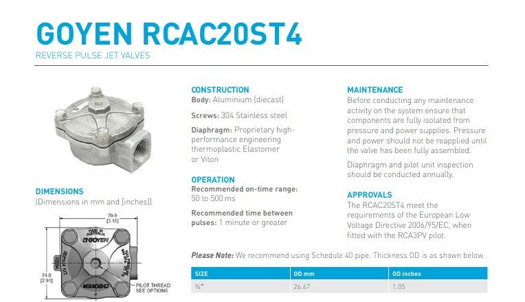
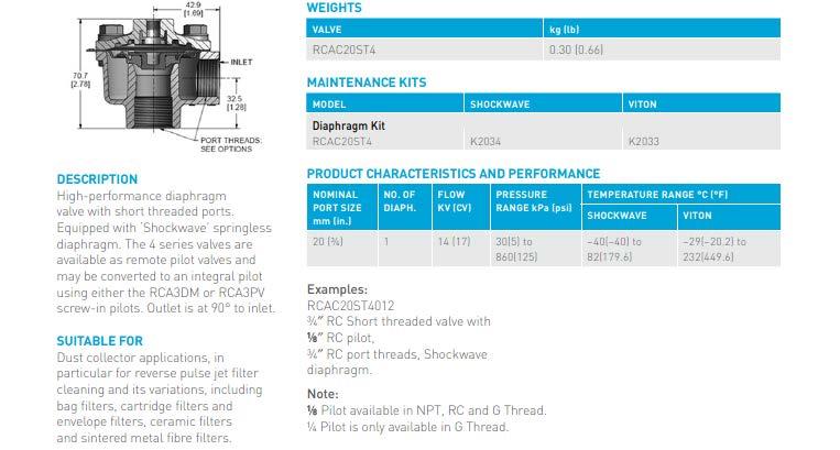
1 Airsweep Installation & Maintenance Manual Airsweep Models VA-06 VA-12 VA-51 SECTION THREE SOLENOID VALVES Model DV1251 / Conduit & DIN Connection Model DV06 / RDV / MCA / RCA Diaphragm Valves Goyen Model RCA3DM & RCAC20ST4 Flexible Hose Assemblies (J11524 & J11512) Trouble Shooting Diaphragm Valves
.")
2 SOLENOID VALVE MODEL DV /2 PULSE VALVE with INTEGRAL SOLENOID PILOT DESCRIPTION: The Myrlen DV1251-series valve is a 2-way quick opening/closing, high flow, diaphragm-type integral solenoid piloted valve. Also available as a remote pilot-operated valve (RDV1251). SOLENOID ENCLOSURES: - DV1251-C or D: Watertight, NEMA Types 1, 2, 3/3S, 4/4X - DV1251-XP: Explosion-Proof and Watertight NEMA Types 3/3S, 4/4X, 6/6P, 7, 9 Type 7: Explosion-Proof Class 1, Division 1, Groups A, B, C & D Type 9: Dust ignition-proof, Class II, Division 1, Groups E, F & G ELECTRICAL (110/120 or 220/240 AC volts, 50/60 Hz)* Watts: 10.1 VA Holding: 25 VA Inrush: 50 *(other AC & DC voltages available). CONSTRUCTION (Parts in contact with fluids) Body: Aluminum (less than 0.4% copper) Seals: Buna N Discs: Buna N Diaphragm: Hytrel* *(Viton seals and diaphragm available for high heat applications) NOMINAL TEMPERATURE RANGES* Ambient & Fluids: 0 F to 150 F (-19 C to 66 C) *For high temperature, specify Viton diaphragm & seals. Viton range: 0 F to 350 F (-18 C to 177 C) Fluid: Air or Nitrogen (inert gas) Working Pressures: Minimum 5 psi. / Maximum 125 psi. Cv flow factor: 53 Pipe size: 1 ½ NPT inlet & outlet and 3/8 NPT exhaust port
3 SOLENOID VALVE MODEL DV1251 Con t OPERATION Valve is Normally Closed when solenoid is de-energized. Valve opens when solenoid is energized. INSTALLATION Check nameplate for correct catalog number, pressure, voltage and service. For DV1251-XP ONLY Caution: to prevent fire or explosion, do not install the DV1251-XP where ignition temperature of hazardous atmosphere is less than 165 C. POSITIONING This valve is designed to perform properly when mounted in any position. NOTE: For optimum life and performance, the solenoid should be mounted vertical and upright to reduce the possibility of foreign matter accumulating in the core tube area. PIPING Connect piping to valve according to markings on valve body (Inlet port is marked with IN ). 3/8 port on upper chamber of valve is exhaust ONLY. Do not connect anything to exhaust port except a high-flow muffler or strainer. Restriction to flow through this port will cause valve to malfunction, operate sluggishly or not operate at all. Thread seal tape is recommended, rather than pipe compound. If compound is used, apply sparingly to male threads only; if applied to valve threads, it may enter the valve and cause operational difficulty. Pipe strain should be avoided by proper support and alignment of piping. When tightening pipe, do not use valve as a lever. Wrenches applied to valve body or piping should be located as close as possible to connection point. CAUTION: To avoid damage to the valve body DO NOT OVERTIGHTEN PIPE CONNECTIONS. If tape thread seal, spray or similar lubricant is used, use extra care due to reduced friction WIRING Wiring must comply with Local and National Electrical Codes. Conduit-style solenoid housings are provided with a hole to accommodate 1/2 inch NPT conduit. The solenoid enclosure may be rotated to facilitate wiring. SOLENOID TEMPERATURE Standard DV1251 valves are supplied with coils designed for continuous duty service. When the solenoid is energized for a long period, the solenoid enclosure becomes hot and can be touched by the hand only for an instant. This is a safe operating temperature. Any excessive heating will be indicated by the smoke and odor of burning coil insulation. FOR DV1251-XP ONLY: The integral solenoid in the DV1251-XP has an internal non-resetable thermal fuse to limit solenoid temperature in the event that extraordinary conditions occur which could cause excessive temperatures. These conditions could include high input voltage, a jammed core, excessive ambient temperature, or a shorted solenoid, etc.
4 SOLENOID VALVE MODEL DV1251 Con t VALVE DISASSEMBLY (Refer to diagram on next page) De-pressurize valve and turn off electrical power supply. If rigid conduit is used it may be necessary to disconnect it. Proceed in the following manner: 1. Disassemble valve in an orderly fashion, paying careful attention to exploded view provided for identification of parts. 2. Remove retaining clip & plate and slip the entire coil enclosure off the solenoid base subassembly. 3. Unscrew solenoid base sub-assembly from pilot bonnet. Remove core assembly, core spring, core guide and solenoid base gasket. 4. Unscrew pilot bonnet screws and remove pilot bonnet and pilot diaphragm assembly. 5. Remove main bonnet screws, main valve bonnet and main diaphragm assembly. 6. All parts are now accessible for cleaning or replacement. Replace worn or damaged parts with a complete spare parts kit for best results. VALVE REASSEMBLY I. Reassemble in reverse order of disassembly paying careful attention to exploded view provided for identification and placement of parts. 2. Lubricate solenoid base gasket with DOW CORNING 111 Compound lubricant or an equivalent high-grade silicone grease. 3. Replace main diaphragm assembly with marking "THIS SIDE OUT" facing main valve bonnet. Be sure that bleed hole in diaphragm assembly is in alignment with cavity in valve body and bonnet. The external contours of the diaphragm assembly, body and bonnet must all be in alignment. 4. Replace main bonnet and bonnet screws. Torque main bonnet screws in a crisscross manner to 160 ± 10 inch-pounds (18,1 ± 1,1 Newton meters). 5. Position pilot diaphragm assembly in valve bonnet. Be sure bleed hole in pilot diaphragm assembly is in alignment with cavity in bonnet. 6. Replace pilot bonnet and pilot bonnet screws. Torque pilot bonnet screws evenly to 95 ± I0 inch-pounds (10,7 ± 1,1 Newton meters). 7. Position core assembly with core spring and core guide into solenoid base sub-assembly. Engage this assembly into the pilot bonnet. Torque solenoid base sub-assembly to 175 ± 25 inch-pounds (19,8 ± 2,8 Newton meters). 8. Replace coil and retaining clip.
5 SOLENOID VALVE MODEL DV1251 Con t MAINTENANCE WARNING Turn off electrical power supply and de-pressurize valve and header before making repairs. NOTE: It is generally not necessary to remove the valve from the pipeline for repairs. CLEANING A periodic cleaning of all solenoid valves is desirable. The time between cleanings will vary depending on medium and service conditions. In general, if the voltage to the coil is correct, sluggish valve operation, excessive noise or leakage will indicate that cleaning is required. PREVENTIVE MAINTENANCE 1. Keep medium flowing through valve as free from dirt and foreign material as possible. 2. While in service, operate valve at least once a month to insure proper opening and closing. 3. Periodic inspection (depending on medium and service conditions) of internal valve parts for damage or excessive wear is recommended. Thoroughly clean all parts, seats and bleed holes. Replace any parts that are worn or damaged. IMPROPER OPERATION 1. Faulty Control Circuits: Check the electrical system by energizing the solenoid. A metallic click signifies the solenoid is operating. Absence of the click indicates loss of power supply. Check for loose or blown-out fuses, open-circuited or grounded coil, broken lead wires, terminals or splice connections. 2. Burned-Out Coil: Check for open-circuited coil; if faulty, replace coil. 3. Low Voltage: Check voltage across coil leads. Voltage must be at least 85% of nameplate rating. 4. Incorrect Pressure: Check valve pressure. Pressure to valve must be within psi. 5. Excessive Leakage or Failure to Open or Close: Check for restrictions to or blockage of exhaust port. Disassemble valve and clean all parts. Check for clogged bleed holes or torn diaphragm assemblies. Replace parts that are worn or damaged with a complete spare parts kit for best results
6 SOLENOID VALVE MODEL DV1251 Con t Parts marked with (*) are supplied in spare parts Kit # RK-DV1251. Torque Chart Torque Value Part Name Inch-Pounds Newton-Meters Solenoid Base Sub-Assembly 175 ± ,8 ± 2,8 Bonnet Screws (pilot) 95 ± 10 10,7 ± 1,1 Bonnet Screws (main) 160 ± 10 18,1 ± 1,1
7 MODEL DV1251 COIL CONNECTION OPTIONS NOTE: DIN Connector Not Available on XP Valves DV1251-C & DV1251-XP (Conduit Connection) DV1251-D (DIN Connection) NOTES: 1. Connector cover may be rotated in 90-degree increments from position shown for alternate position of cable entry. 2. Refer to markings on DIN connector for proper electrical connections.
8 DV1251 DIAPHRAGM VALVE WITH INTEGRATED SOLENOID 1-1/2 RDV1251 REMOTE PILOT-OPERATED DIAPHRAGM VALVE 1-1/2
.")
9 SOLENOID VALVE MODEL DV06 3/4 PULSE VALVE with INTEGRAL SOLENOID PILOT DESCRIPTION: The Myrlen DV06-series valve is a 2-way quick opening/closing, high flow, piston diaphragm-type integral solenoid piloted valve. Also available as a remote pilot-operated valve (Model RDV06). SOLENOID ENCLOSURES: - DV06-C: Watertight, NEMA Types 1, 2, 3/3S, 4/4X - DV06-XP: Explosion-Proof and Watertight NEMA Types 3/3S, 4/4X, 6/6P, 7, 9 Type 7: Explosion-Proof Class 1, Division 1, Groups A, B, C & D Type 9: Dust ignition-proof, Class II, Division 1, Groups E, F & G ELECTRICAL (110/120 or 220/240 AC volts, 50/60 Hz)* Watts: 10.1 VA Holding: 25 VA Inrush: 50 *(other AC & DC voltages available). CONSTRUCTION (Parts in contact with fluids) Body: Aluminum (less than 0.4% copper) Seals: Buna N Discs: Buna N Diaphragm: Hytrel NOMINAL TEMPERATURE RANGES Ambient & Fluids: 0 F to 150 F (-19 C to 66 C) Fluid: Air or Nitrogen (inert gas) Working Pressures: Minimum 5 psi. / Maximum 125 psi. Cv flow factor: 15 Pipe size: 3/4 NPT inlet & outlet. Total Assembly Weight: 1.5 lbs.
10 SOLENOID VALVE MODEL DV06 EXPLODED VIEW WITHOUT COIL Torque screws to 62 (± 9) in-lbs. Parts marked (*) Included in parts kit # RK-DV06-08 Piston sub-assembly available individually (Part Number: C )
11 DV06 DIAPHRAGM VALVE WITH INTEGRAL SOLENOID 3/4 RDV06 REMOTE PILOT-OPERATED DIAPHRAGM VALVE 3/4
12 8262 PILOT VALVE FOR REMOTE PILOT-OPERATED DIAPHRAGM VALVES (RDV-series)
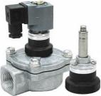
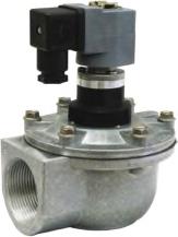
13 Model MCA/RCA Diaphragm Valves (3/4 & 1 1 / 2 ) Dimensions (inches) Model Orifice A B C (Width) D E RCA-20T 3 / RCA-45T 1 1 / MCA-20T 3 / MCA-45T 1 1 / Pilot Connections: 1/8 NPT Exhaust Connections: MCA/RCA 20 1/8 NPT MCA/RCA 45 3/8 NPT SPARE PARTS KITS Solenoid Kit Diaphragm Kit Model Buna N Viton Buna N Viton MCA/RCA-20T M1131B M1167B K2000 M2082 MCA/RCA-45T M1131B M1167B K4502 M2163

14 MCA/RCA-SERIES DIAPHRAGM VALVE PARTS LIST ITEM Description Quantity ITEM Description Quantity 1 Body 1 13 O-Ring 1 2 Main Bleed Pin 1 14 Plunger 1 3 Main Diaphragm 1 15 Spring, Plunger 1 Assembly 4 Spring, Main Diaphragm 1 16 Ferrule Assembly 1 5 Main Cover 1 17 O-Ring 1 6 Hexagonal Screw 4 or 6 18 Ferrule Retainer 1 7 Secondary Bleed Pin 1 19 Screw 3 8 Secondary Diaphragm 1 20 Wave Washer 1 9 Spring, Sec. Diaphragm 1 21 Coil (QR/QD) 1 10 Secondary Cover (RCA) 1 22 Nameplate 1 Socket Screw 4 23 Clip 1
15
16
17 Flexible Hose Assembly 1 ½ Part Number J11524 Hose Specifications: 1 ½ i.d. x 24 overall length Tube: Black Versigard synthetic rubber Cover: Black Versigard synthetic rubber, wrapped finish with yellow spiral stripe Reinforcement: Spiral plied synthetic fabric with wire helix Temperature Range: -40 F to 180 F (-40 C to 82 C) Working Pressure: 125 PSI (0.86 Mpa) Bend Radius: 4.0 in / 102 mm Male Nipple: 1-1/2 NPT plated steel Punch-Lok band clamps, both ends Available in custom lengths with choice of fittings.
18 Flexible Hose Assembly ¾ Part number J /4" NPT barbed-shank nipple (typ. both ends) Punch-Lok Steel Band (typ. both ends) Flexible hose 300 psi w.p. (total assembly 24" OVL) Hose Specifications Tube: Chemigum, RMA Class A (High Oil Resistance). Cover: Red Chemivic, RMA Class B (Medium-High Oil Resistance) Reinforcement: Spiral synthetic yarn Temperature Range: -20 F to 190 F (-29 C to 88 C). Working Pressure: 300 PSI / 2.1 Mpa Nominal I.D.: ¾ / mm Nominal O.D.: / 30.2 mm Non-conductive Dixon STC5 shank nipple, plated steel, ¾ male NPT Punch-lok banded, both ends Available in custom lengths with choice of fittings.
19 TROUBLE SHOOTING DIAPHRAGM VALVES PROBLEM 1. Diaphragm Valve fails to operate (open) 2. Diaphragm Valve fails to shut 3. Unable to build header pressure 4. Sluggish operation of diaphragm valve POSSIBLE CAUSE No pressure in header Low or no power to coil Coil inoperative Pilot valve plunger jammed shut Pilot orifice blocked Secondary bleed-hold blocked Main diaphragm perforated Secondary diaphragm perforated Pilot valve connecting line too long Silencer, if fitted, may be blocked Pilot valve plunger jammed open Foreign matter under pilot valve Secondary diaphragm spring broken Foreign matter under secondary diaphragm Main diaphragm spring broken Foreign matter under main diaphragm Main diaphragm seating disc damaged Main bleed hole blocked Secondary bleed hole blocked Leak in line connecting pilot valve Excessive leakage from main diaphragm seat Broken main valve spring Secondary diaphragm not seating Foreign matter under main or secondary diaphragm seat or under pilot valve seat Air supply line too small Compressor too small Partial blockage of one of the bleed-holes Silencer, if fitted, may be blocked
20 TROUBLE SHOOTING DIAPHRAGM VALVES Con t SPECIAL NOTE To prevent premature failure of a diaphragm valve, special attention must be paid to the quality of the compressed air/gas being handled. An adequate moisture and oil removal system must be incorporated that takes into account: relative humidity likely to be experienced ambient temperatures system operating temperatures pressure drops (and associated temperature drops) through the valve and also through the blow tube holes (dew point problem) Also, small traces of chlorine and other aggressive gases, often present in filter systems, can be absorbed in wet areas resulting in corrosion and premature failure. Apart from valve failures, systems may not perform to expectation for a number of reasons including the following: inaccurate mounting/positioning of the Airsweep(s) relative to the vessel wall inadequately sized header and/or air supply incorrect pulse time incorrect intervals between pulses improper adjustment or wear of Airsweep(s) piston head
21 Thank you for your interest in our Airsweep Systems line of products. Please do not hesitate to contact us regarding any questions you may have, or if you would like to request a free design consultation and estimate. Myrlen Airsweep Systems Division of Control Concepts, Inc Toll Free (800) Fax (888) Info@AirsweepSystems.com Control Concepts Inc. Helps Reduce Risk by Keeping Materials Flowing Safely and Economically Through Your Plant If you would like to learn about our line of Zero Speed Switches and AcoustiClean Sonic Horns, please contact us at: Control Concepts, Inc 100 Park Street Putnam, CT Toll Free (800) Fax (860) Sales@ControlConceptsUSA.com
Installation & Maintenance Instructions
 Installation & Maintenance Instructions OPEN-- FRAME, GENERAL PURPOSE, WATERTIG/EXPLOSIONPROOF SOLENOIDS r SERIES 8016G/H (Section1of2) SERVICE NOTICE ASCOr solenoid valves with design change letter G
Airsweep System Installation, Operations and Maintenance Manual
 Airsweep System Installation, Operations and Maintenance Manual Table of Contents Section Pages General installation notes, system overview 1-2 VA-51 Airsweep and mounting 3-4 VA-12 Airsweep and mounting
SERIES ASCO Valves DESCRIPTION OPERATION INSTALLATION. Positioning. Page1of5(Section1of2) I&M No.V9575R3 (Section1of2)
 I&M No.V9575R3 (Section1of2)") Installation & Maintenance Instructions -- WAY DIRECT-- ACTING SOLENOID VALVES REVISION H & R NORMALLY OPEN OR NORMALLY CLOSED OPERATION BRASS OR STAINLESS STEEL CONSTRUCTION -- 1/8I, 1/4I, OR3/8I PIPE
Installation & Maintenance Instructions -- WAY DIRECT-- ACTING SOLENOID VALVES REVISION H & R NORMALLY OPEN OR NORMALLY CLOSED OPERATION BRASS OR STAINLESS STEEL CONSTRUCTION -- 1/8I, 1/4I, OR3/8I PIPE
Easytork Solenoid Valve IOM
 Easytork Solenoid Valve IOM General This installation document is to be read in conjunction with the Easytork Vane Actuator IOM. Description The Easytork Solenoid Valve ( ESV ) series is intended for the
CIRCLE SEAL CONTROLS
 CIRCLE SEAL CONTROLS ATKOMATIC SOLENOID VALVES INSTALLATION, MAINTENANCE, AND OPERATION INSTRUCTIONS 3000 SERIES Bronze, Normally Closed, Direct Lift Installation Instructions WARNING: These instructions
CIRCLE SEAL CONTROLS
 CIRCLE SEAL CONTROLS ATKOMATIC SOLENOID VALVES INSTALLATION, MAINTENANCE, AND OPERATION INSTRUCTIONS 13000 SERIES Stainless, Normally Closed, Direct Lift, 3-Way Valve Installation Instructions WARNING:
AIRSWEEP MAINTENANCE
 Airsweep Installation & Maintenance Manual Airsweep Models VA-06 VA-12 VA-51 SECTION SIX AIRSWEEP MAINTENANCE Requirements & Instructions Repair Kit Components - VA-51-T / VA-51 / VA-12 / VA-06 Solenoid
Engineering Information. Solenoid Valves Principles of Operation. Solenoid Valves. Direct Acting Valves (Figures 1A, 1B)
") 4 Engineering Information Principles of Operation A solenoid valve is a combination of two basic functional units: A solenoid (electromagnet) with its core A valve body containing one or more orifices
4 Engineering Information Principles of Operation A solenoid valve is a combination of two basic functional units: A solenoid (electromagnet) with its core A valve body containing one or more orifices
4 qwer. Main Pulse Valves Dust Collector 2/2 SERIES H OME PAGE P RINT. High Flow. Aluminum Bodies Air and Inert Gas 3/4" to 3" NPT.
 4 qwer High Flow Main Pulse Valves Aluminum Bodies Air and Inert Gas 3/4" to 3" NPT NC 2/2 SERIES Features Specially designed for reverse jet-type dust collector systems. High flow Cv s to 140 for effective
Installation, Operation and Maintenance Manual
 Installation, Operation and Maintenance Manual Technical Manual EH 1.2 General Information about valve sizing: Valves with a Full Port have an internal seat diameter that is the same as the nominal pipe
Product Manual. EX40, Version Last Updated: 11/7/16. Product Description:
 Product Manual EX40, Version 2016.1 Last Updated: 11/7/16 Product Description: The EX40 Series encompasses 2-way piloted solenoid valves with a maximum allowable inlet pressure of 15,000 psi [103.4 MPa].
INSTALLATION, OPERATION AND MAINTENANCE MANUAL (IOM)
") INSTALLATION, OPERATION AND MAINTENANCE MANUAL (IOM) IOM-1088 03-16 Model 1088 Vacu-Gard Blanketing Valve ISO Registered Company SECTION I I. DESCRIPTION AND SCOPE The Model 1088 Vacu-Gard is a tank blanketing
INSTALLATION, OPERATION AND MAINTENANCE MANUAL (IOM) IOM-1088 03-16 Model 1088 Vacu-Gard Blanketing Valve ISO Registered Company SECTION I I. DESCRIPTION AND SCOPE The Model 1088 Vacu-Gard is a tank blanketing
t EVAPORATOR PRESSURE REGULATING VALVES
 CATALOG 201 Page 63 t EVAPORATOR PRESSURE REGULATING VALVES (S)ORIT-12, -15 and -20 Features n High side pilot for improved temperature control and low P operation n Adjustable n Optional solenoid stop
Three Way Pilot Control
 136-03/636-03 Description The CIa-VaI Model 100-01 Hytrol Valve is a main valve for CIa-VaI Automatic Control Valves. It is a hydraulically operated, diaphragm-actuated, globe or angle pattern valve.
Installation Operation Maintenance. LSSN Butterfly Valve AGA Approved 50MM - 150MM. QAD#IM6055.REVA
 LSSN Butterfly Valve Installation Operation Maintenance Licence Number: 5326 www.challengervalves.com.au 1 Index 1. INTRODUCTION 1.1 Design Features 3 1.2 Flange and Pipe Compatibility 4 1.3 Operating
MARFAID Solenoid Valves
 Series 125 2-Way Normally Closed Pilot Operated Diaphragm Type Bronze Construction Wide Variety of Voltages Maximum Temperature 190 F Pressure Range 5-150 psi Horizontal or Vertical Installation 1-15 4"
Ideal Installation. I & M Mark 67 (1/2 6 ) Control Line. Installation & Maintenance Instructions for Mark 67 Pressure Regulators
 Control Line. Installation & Maintenance Instructions for Mark 67 Pressure Regulators") I & M Mark (/ ) 0 Wasson Road Cincinnati, OH 0 USA Phone --00 Fax -8-00 info@richardsind.com www.jordanvalve.com Installation & Maintenance Instructions for Mark Pressure Regulators Warning: Jordan Valve
I & M Mark (/ ) 0 Wasson Road Cincinnati, OH 0 USA Phone --00 Fax -8-00 info@richardsind.com www.jordanvalve.com Installation & Maintenance Instructions for Mark Pressure Regulators Warning: Jordan Valve
I & M 8000 Series. Ideal Installation Schematic. Preferred Installation. Trouble Shooting
 I & M 8000 Series 3170 Wasson Road Cincinnati, OH 45209 USA Phone 513-533-5600 Fax 513-871-0105 lowflow@richardsind.com www.lowflowvalve.com Installation & Maintenance Instructions for 8000 Series Low
Model and Series 115 VAC INDUSTRIAL DIAPHRAGM PUMPS. PumpAgents.com - buy pumps and parts online INDUSTRIAL DIAPHRAGM PUMPS
 Model 31801 and 31800 Series 115 VAC INDUSTRIAL DIAPHRAGM PUMPS INDUSTRIAL DIAPHRAGM PUMPS FEATURES Run Dry Ability Self-Priming Thermal Overload Protected Motor Easy Installation Low Amp Draw Compact
4 qwer 2/2. Pilot Operated General Service Solenoid Valves. Brass or Stainless Steel Bodies 3/8" to 2 1/2" NPT. Features. Construction.
 4 qwer Pilot Operated General Service Solenoid Valves Brass or Stainless Steel Bodies 3/8" to 2 1/2" NPT NC NO 2/2 SERIES Features Wide range of pressure ratings, sizes, and resilient materials provide
High Pressure Solenoid Valves
 High Pressure Solenoid Valves Available for Quick Delivery Controls the flow of Gases & Liquids up to 15,000 PSIG Natural Gas, Hydrogen & other High Pressure Gases High Pressure Cryogenics Flammable Liquids
Thank You for Attending Today s Webinar. Today s Featured Speaker
 Instruments, Valves, and Controls Thank You for Attending Today s Webinar Your Host Mike DeLacluyse President Lesman Instrument Company miked@lesman.com Today s Featured Speaker Mike Unterreiner Senior
ITVX Series. Stepless control of air pressure proportional to an electrical signal. Supply pressure: 5.0 MPa
 5.0 MPa Maximum Supply Pressure High Pressure Electro-Pneumatic Regulator X Series This product is only for blowing gas. This product does not have sufficient pressure control for other applications (driving,
MAINTENANCE MANUAL FOR THERMOSTATIC TEMPERATURE REGULATING VALVE TRAC STYLE P
 MANUAL NUMBER P-EFS-1 MAINTENANCE MANUAL FOR THERMOSTATIC TEMPERATURE REGULATING VALVE TRAC STYLE P TRAC Regulator Company Inc. 160 South Terrace Avenue Mount Vernon, New York USA 10550-2408 Phone: (914)
Air Trap TATSU2. Copyright 2013 by TLV CO., LTD. All rights reserved ISO 9001/ ISO M-02 (TATSU2) 7 August 2013.
 7 August 2013.") 172-65177M-02 (TATSU2) 7 August 2013 ISO 9001/ ISO 14001 Manufacturer Kakogawa, Japan is approved by LRQA LTD. to ISO 9001/14001 Air Trap TATSU2 Copyright 2013 by TLV CO., LTD. All rights reserved 1 Contents
172-65177M-02 (TATSU2) 7 August 2013 ISO 9001/ ISO 14001 Manufacturer Kakogawa, Japan is approved by LRQA LTD. to ISO 9001/14001 Air Trap TATSU2 Copyright 2013 by TLV CO., LTD. All rights reserved 1 Contents
SD Bendix E-10PR Retarder Control Brake Valve DESCRIPTION. OPERATION - Refer to Figure 2
 SD-03-832 Bendix E-10PR Retarder Control Brake Valve MOUNTING PLATE SUPPLY 4 PORTS ELECTRICAL AUXILIARY DESCRIPTION TREADLE RETARDER CONTROL SECTION EXHAUST DELIVERY 4 PORTS FIGURE 1 - E-10PR RETARDER
Installation& Maintenance Instructions
 Installation& Maintenance Instructions HS2 Valve Position Monitor With Integrated Valve Notice: These instructions are divided into two sections. Be sure to read, understand and follow all instructions
2-Way/2 Position Valves
 4 2-Way/2 Position Valves Two-way solenoid valves have one inlet and one outlet, and are used to permit and shut off fluid flow. Two Types of Operations Apply Normally Closed (NC) Fluid is shut off when
Air Operated Double Diaphragm Pump. M-Pump ½ Metallic Non Metallic Pump INSTALLATION, OPERATION & MAINTENANCE MANUAL
 Air Operated Double Diaphragm Pump M-Pump ½ Metallic Non Metallic Pump INSTALLATION, OPERATION & MAINTENANCE MANUAL 0.5 I.O.M rev 05. 12/2015 INDEX Title Section Introduction.1 Safety.2 Warranty, General
Model &
 PumpAgents.com - Click here for Pricing/Ordering Model 31765-0092 & 31765-0094 Dual Sensor Max VSD WATER PRESSURE SYSTEM AUTOMATIC TWO STAGE WATER SYSTEM WITH PUMPGARD STRAINERS IDEAL FOR PLEASURE AND
EH50 Product Manual Version
 EH50 Product Manual Version 2015.3 Last Updated: 3/2/15 J.Koba Product Description: The EH50 Series encompasses 2-way, pilot operated solenoid valves with a maximum allowable inlet pressure of 10,000 psi
SOLENOID CONTROL VALVE
 PROJECT NAME LOCATION SOLENOID CONTROL VALVE INTRODUCTION This specification covers the design, manufacture, and testing of 4 in. (100 mm) through 36 in. (900 mm) Control Valves PART 1 - GENERAL 1. Standard
ANDERSON GREENWOOD SERIES 500 PILOT OPERATED SAFETY RELIEF VALVES INSTALLATION AND MAINTENANCE INSTRUCTIONS
 Before installation these instructions must be fully read and understood TABLE OF CONTENTS 1. General valve description and start-up... 1 2. Main valve maintenance... 1 3. Pilot maintenance... 5 4. Pilot
MicroCoat. System Operating Manual MC2000 Series. MC785, MC785-WF Spray Valves. US: UK: Mexico:
 MicroCoat System Operating Manual MC2 Series MC785, MC785-WF Spray Valves A NORDSON COMPANY US: 8-498-8865 UK: 8 585733 Mexico: 1-8-556-3484 Introduction The MicroCoat System provides precise lubrication
MODEL MC1500 Installation and Operation Manual Important:
 MODEL MC1500 Installation and Operation Manual Important: This manual contains specific cautionary statements relative to worker safety. Read this manual thoroughly and follow as directed. It is impossible
Maintenance Manual Reduced Pressure Assembly Models 860 & 880V 2 1 /2" 10"
 IOM-F-860_880V INSTALLATION, OPERATION, MAINTENANCE Maintenance Manual Reduced Pressure Assembly Models 860 & 880V 2 1 /2" 10" 860 880V Standard Configuration 880V Vertical Configuration INDEX Vandalism..............................................
Adjustable Differential Relay A1
 Sales Manual Section 332 PRODUCT SPECIFICATION MODEL 84871-A1 GENERAL DESCRIPTION The 84871-A1 Adjustable Differential Diverting Relay is a two-position, snap-acting, three-way relay. Its normal function
Q= C. v P S Refer to Table 1 for part numbers and shipping weights. Accessories: Table 1: Valve Part Numbers and Specifications
 1 of 9 1. DESCRIPTION The Viking Flow Control Valve is a quick opening, differential diaphragm flood valve with a spring loaded floating clapper. The Flow Control Valve can be used to facilitate manual
NYLON & PVC VALVES MINING DIVISION PRESSURE REDUCING VALVES ENSURE DOWNSTREAM PRESSURE PVC NYLON
 MINING DIVISION NYLON & PVC VALVES PRESSURE REDUCING VALVES ENSURE DOWNSTREAM PRESSURE NYLON For Gold Mines DESCRIPTION The valve maintains a preset downstream pressure, regardless of upstream pressure
I & M Mark 708ME. Ideal Installation. Start-Up Procedure. Installation & Maintenance Instructions for Mark 708 & Motor Actuator
 I & M Mark 708ME 3170 Wasson Road Cincinnati, OH 45209 USA Phone 513-533-5600 Fax 513-871-0105 info@richardsind.com www.lowfl owvalve.com Installation & Maintenance Instructions for Mark 708 & Motor Actuator
COMBINATION PRESSURE REDUCING AND SOLENOID SHUTOFF CONTROL VALVES 2.01 COMBINATION RESSURE REDUCING AND SOLENOID SHUTOFF CONTROL VALVE
 PROJECT NAME LOCATION COMBINATION PRESSURE REDUCING AND SOLENOID SHUTOFF CONTROL VALVES INTRODUCTION This specification covers the design, manufacture, and testing of 1 in. (25 mm) through 36 in. (900
45 VALVE SERIES. 2-Position 4-Way 5-Ports, Installation & Service Instructions. Valve with Stem Operator, Installation & Service Instructions
 (02/20/8) Pneumatic Division Richland, Michigan USA www.parker.com/pneumatics Document Number V275CP V280CP V284CP V32CP 45 VALVE SERIES Description 3-Position 4-Way 5-Ports, Installation & Service Instructions
Stainless Steel Pilot Piston Solenoid Valve 2MS Series for High Temperature & High Pressure
 Stainless Steel Pilot Piston Solenoid Valve 2MS Series for High Temperature & High Pressure S T C TM To Order, Please Specify: 1) Model No., 2) Voltage 2 Way, NC Pilot Piston Stainless Steel Part No. Voltage
3 Way/2 Position Valves
 Way/ Position Valves Three way valves have three pipe connections and two orifices. When one orifice is open, the other is closed, and vice versa. They are commonly used to alternately apply pressure to
5.0 MPa Pilot Operated 2/3 Port Solenoid Valve & Check Valve
 5.0 MPa Pilot Operated / Port Solenoid Valve & Check Valve Series VCH VCH4/4: Port VCH40: Port VCHC40: Check Valve Pilot Operated Port Solenoid Valve Series VCH40 Stable responsiveness Response time dispersion
PNEUMATICS CONTENTS HST-TAMPER
 CONTENTS Tamper Pneumatic Component Locations...2 Manually Releasing Air Brakes... 3 Releasing Air Pressure... 4 Removing Water from Air Tanks... 4 Adjusting Air Compressor Governor... 4 Check/Replace
ATEX/IECEx Coil Manual Type 200 and 300 Series Coils for EH70 Series Solenoid Valves Issue , Released December 13, 2017
 ATEX/IECEx Coil Manual Type 200 and 300 Series Coils for EH70 Series Solenoid Valves Issue 2017.1, Released December 13, 2017 Clark Cooper A Division of Magnatrol Valve Corp. 941 Hamilton avenue Roebling,
TYPE E Main Valve Sizes 3 /8 through 12
 Technical Data SD 3001E PRINTED IN U.S.A. SD 3001E/9709 SPENCE ENGINEERING COMPANY, INC. 150 COLDENHAM ROAD, WALDEN, NY 12586-2035 A B TYPE E MAIN VALVE FACE TO FACE DIMENSIONS C D E DIMENSIONS (inches)
ANDERSON GREENWOOD. Before installation these instructions must be fully read and understood.
 ANDERSON GREENWOOD Before installation these instructions must be fully read and understood. 1.1 General The Anderson Greenwood Series 200 Pilot Operated SRV uses the principle of pressurizing the larger
Scope. Applicability. Caution. I & M CV3000 Series. Storage. Installation & Maintenance Instructions for Marwin CV3000 Series Three Piece Ball Valves
 I & M CV3000 Series 3170 Wasson Road Cincinnati, OH 45209 USA Phone 513-533-5600 Fax 513-871-0105 marwin@richardsind.com www.marwinvalve.com Installation & Maintenance Instructions for Marwin CV3000 Series
INSTALLATION/OPERATION/MAINTENANCE INSTRUCTIONS FOR ARCHON MODELS WD2010L, WD2010, WD2010H WASHDOWN STATIONS. ARCHON Industries, Inc.
 ARCHON Industries, Inc. Washdown Stations Models WD2010L, WD2010, WD2010H Installation / Operation / Maintenance Instructions 1 This manual has been prepared as an aid and guide for personnel involved
I & M Mark 78 Series. Ideal Installation. Start-Up. Installation & Maintenance Instructions for Mark 78 Control Valves (1-1/2-2 )
") I & M Mark 8 Series 0 Wasson Road Cincinnati, OH 4509 USA Phone 5-5-5600 Fax 5-8-005 info@richardsind.com www.jordanvalve.com Installation & Maintenance Instructions for Mark 8 Control Valves (-/ - ) Warning:
I & M Mark 8 Series 0 Wasson Road Cincinnati, OH 4509 USA Phone 5-5-5600 Fax 5-8-005 info@richardsind.com www.jordanvalve.com Installation & Maintenance Instructions for Mark 8 Control Valves (-/ - ) Warning:
CUSTOM COMBINATION AIR VALVE
 INSTALLATION / OPERATION / MAINTENANCE CUSTOM COMBINATION AIR VALVE INTRODUCTION This manual will provide you with the information to properly install and maintain this valve to ensure a long service life.
 138-01/638-01 MODEL 100-01 (Sizes 3/8"-36") Hytrol Valve Drip-Tight, Positive Seating Service Without Removal From Line Threaded, Flanged or Grooved Ends Globe or Angle Pattern 100% Factory Tested
MOUNTING, OPERATING, TESTING & MAINTENANCE INSTRUCTIONS FOR ROTEX 5/2 INTERNAL PILOT OPERATED, POPPET TYPE SINGLE SOLENOID VALVE MODEL 51440NP
 Page 1 of 6 MOUNTING, OPERATING, TESTING & MAINTENANCE INSTRUCTIONS FOR ROTEX 5/2 INTERNAL PILOT OPERATED, POPPET TYPE SINGLE SOLENOID VALVE MODEL 51440NP ROTEX retains all rights to this publication.
NOZZLETECH INC. INSTRUCTION MANUAL CEV00 01/31/ C EAST COLONIAL DRIVE ORLANDO, FL USA
 NOZZLETECH INC. 3208C EAST COLONIAL DRIVE ORLANDO, FL 32803 USA INSTRUCTION MANUAL CEV00 01/31/2013 NOZZLETECH CEV00 SERIES COMPACT ELECTRIC VALVES FOR EXTRUSION RELATED PATTERNS WARNING: The fluid supply
Pneumatic Division North America Richland, MI 49083
 Pneumatic Division North America Richland, MI 08 Installation Instructions: V-0P /8" Valvair II/A Series Valves Single Operated ISSUED: May, 00 Supersedes: November, 8 ECN #6 Rev. 6 WARNING To avoid unpredictable
Pressure Sensor No Series
 Sales Manual Section 335 PRODUCT SPECIFICATION 84372 SERIES Pressure Sensor No. 84372-Series GENERAL DESCRIPTION The patented* No. 84372-Series Pressure Sensor contains a weatherproof, snap-acting valve
TECHNICAL DATA 1-1/2 (dn40)
") July 1, 2011 Deluge Valves 209a DESCRIPTION The Viking Model E-3 1-1/2 Deluge Valve is a quick-opening, differential type flood valve with a rolling diaphragm clapper. The deluge valve is used to control
July 1, 2011 Deluge Valves 209a DESCRIPTION The Viking Model E-3 1-1/2 Deluge Valve is a quick-opening, differential type flood valve with a rolling diaphragm clapper. The deluge valve is used to control
I & M Mark 78 Series. Ideal Installation. Start-Up. Installation & Maintenance Instructions for Mark 78 Control Valves (1/2-1 )
") I & M Mark 8 Series 30 Wasson Road Cincinnati, OH 4509 USA Phone 53-533-5600 Fax 53-8-005 info@richardsind.com www.jordanvalve.com Installation & Maintenance Instructions for Mark 8 Control Valves (/ -
I & M Mark 8 Series 30 Wasson Road Cincinnati, OH 4509 USA Phone 53-533-5600 Fax 53-8-005 info@richardsind.com www.jordanvalve.com Installation & Maintenance Instructions for Mark 8 Control Valves (/ -
TECHNICAL DATA. Viking Technical Data may be found on Style: 90 Degree Pattern (inlet to outlet)
") Flow Control 500a DESCRIPTION The Viking 1-1/2 is a quick opening, differential type flood valve with a spring loaded rolling diaphragm clapper. The can be used to facilitate manual or automatic on/off
Flow Control 500a DESCRIPTION The Viking 1-1/2 is a quick opening, differential type flood valve with a spring loaded rolling diaphragm clapper. The can be used to facilitate manual or automatic on/off
Operating and Maintenance Manual for Type S Flowmeters. M101 Rev. B Type S Flowmeters: 5 8, 3 4 and 1 with 157 & 600 Series Registers
 Operating and Maintenance Manual for Type S Flowmeters M101 Rev. B Type S Flowmeters: 5 8, 3 4 and 1 with 157 & 600 Series Registers TABLE OF CONTENTS Installation & Operation... Page 1 Calibration...
PD3/PDV3-20A/25A/40A Series
 Pilot operated 2-port valve for dust collector control (Large port size dust collector valve) PD3/PDV3-20A/25A/40A Series Air operated/with solenoid valve Port size: Rc3/4, Rc1, : Rc1 1 /2-: φ48, Rc1 1
for ½" thru 2" 800 lb. Piston Lift Check Valves with Resilient Seat Option
 Manual No. 800-PC Issued: March 31, 2004 INSTRUCTION MANUAL for ½" thru 2" 800 lb. Piston Lift Check Valves with Resilient Seat Option Flowserve Corporation Flow Control Division 1900 S. Saunders Street
Installation, Operation, and Maintenance Manual Full Port Y-Pattern, Bolted Bonnet, Globe and Check Valves
 SMITH VALVES Installation, Operation, and Maintenance Manual Full Port Y-Pattern, Bolted Bonnet, Globe and Check Valves Globe Valve Series: YG80/YG15 Welded Bonnet Globe Valve Series: YG87/YG17 Piston
MULTIPOSITION AIR CYLINDER
 MULTIPOSITION AIR CYLINDER CAST ALUMINUM FOUR-POSITION - ALL AIR SERVICE INFORMATION MOUNTING! Devices should be mounted and positioned in such a manner that they cannot be accidentally operated. INSTALLATION
Installation Instructions
 Page 6300-S-1 Installation Instructions 1. Read complete instructions before proceeding and do not discard packing materials until any/all loose items are located. Also, make sure that the installation
5.0 MPa Pilot Operated 2/3 Port Solenoid Valve & Check Valve
 5.0 Ma ilot Operated /3 ort Solenoid Valve & Check Valve Series VCH VCH4/4: ort VCH40: 3 ort VCHC40: Check Valve ilot Operated ort Solenoid Valve [Option] Series VCH40 Stable responsiveness Response time
MicroCoat System Operating Manual MC4000 Series MC785M, MC785M-WF Spray Valves
 MicroCoat System Operating Manual MC Series MC785M, MC785M-WF Spray Valves A NORDSON COMPANY Introduction The MicroCoat System provides precise lubrication control for metal stamping operations. The MC
BC-VDC A TOTAL SYSTEM FOR YOUR DUST COLLECTOR DWYER INSTRUMENTS, INC. DWYER OFFERS YOU:
 BC-VDC SPRINGLESS DIAPHRAGM PULSE VALVES DCS/RDCS SPRINGLESS DIAPHRAGM PULSE VALVES Ease of Installation: Industry standard right angle body with 90 angle between inlet and outlet. Most sizes offer the
Technical Data TYPE T124 & T134 TEMPERATURE PILOT SPENCE ENGINEERING COMPANY, INC. 150 COLDENHAM ROAD, WALDEN, NY SD 4512A
 WATTS INDUSTRIES, INC. Technical Data SD 4512A SPENCE ENGINEERING COMPANY, INC. 150 COLDENHAM ROAD, WALDEN, NY 12586-2035 PRINTED IN U.S.A. SD 4512A/9806 T124/T134 PILOT FRONT VIEW 2 1 /16 F 5 7 /8 2 3
Fisher 657 Diaphragm Actuator Sizes and 87
 Instruction Manual 657 Actuator (30-70 and 87) Fisher 657 Diaphragm Actuator Sizes 30 70 and 87 Contents Introduction... 1 Scope of Manual... 1 Description... 2 Specifications... 2 Installation... 3 Mounting
FAIRCHILD T5200 SERIES ELECTRO-PNEUMATIC TRANSDUCER Installation, Operation and Maintenance Instructions
 FAIRCHILD T500 SERIES ELECTRO-PNEUMATIC TRADUCER Installation, Operation and Maintenance Instructions Identification Number Underwriting Group Factory Mutual Canadian Standard T (F) (C) 500- Approval Class
HALLMARK INDUSTRIES INC
 Performance Part No. HP. CONVERTIBLE JET PUMP USER S MANUAL GPH of Water @ Total Discharge Pressure of 40 psi Max. Pressure Max suction (shallow well) Max Suction (deep well) Max GPM (@0 head) Max Discharge
DT34 and DT54 Series Rotary Sprinklers
 DT34 and DT54 Series Rotary Sprinklers Installation & Service Instructions Introduction The DT34 and DT54 series full-circle rotary sprinklers are designed specifically for golf course applications. Manufactured
Model DV-5 Deluge Valve, Diaphragm Style, 1-1/2 thru 8 Inch (DN40 thru DN200), Deluge System Electric Actuation
, Deluge System Electric Actuation") Deluge Valve DV-5 Model DV-5 Deluge Valve, Diaphragm Style, 1-1/2 thru 8 Inch (DN40 thru DN200), Deluge System Electric Actuation GeneralDescription The Model DV-5 Deluge Valve (described in Technical
Deluge Valve DV-5 Model DV-5 Deluge Valve, Diaphragm Style, 1-1/2 thru 8 Inch (DN40 thru DN200), Deluge System Electric Actuation GeneralDescription The Model DV-5 Deluge Valve (described in Technical
MOUNTING, OPERATING, TESTING & MAINTENANCE INSTRUCTIONS FOR ROTEX 3/2 DIRECT ACTING ON/OFF/REGULATING NAMUR SOLENOID VALVE MODEL 30318, 30318LW
 Page 1 of 5 MOUNTING, OPERATING, TESTING & MAINTENANCE INSTRUCTIONS FOR ROTEX 3/2 DIRECT ACTING ON/OFF/REGULATING NAMUR SOLENOID VALVE MODEL 30318, 30318LW ROTEX retains all rights to this publication.
Cla-Val. Service Training Manual. Simple solutions plus learning with a purpose
 Cla-Val Service Training Manual Simple solutions plus learning with a purpose 5 Application Series Section General Identify What Valve You Have 5-1 Rate of Flow 40 Series 5-2 Pressure Relief 50 Series
TECHNICAL DATA CAUTION
 Page 1 of 6 1. DESCRIPTION The Viking Model D-2 Accelerator is a quick-opening device, with an integral anti-flood assembly, used to increase the operating speed of a differential type dry pipe valve.
SD Bendix TC-4 Modulating Control Valve TYPICAL PIPING DIAGRAM EXHAUST PORT DELIVERY PORT DELIVERY PORT FIGURE 1 SUPPLY PORT FIGURE 2
 SD-03-4503 Bendix TC-4 Modulating Control Valve EXHAUST DELIVERY DELIVERY FIGURE 1 SUPPLY TC-2 TP-2 TRAILER SERVICE BRAKE CHAMBERS GAUGE TW-1 MANIFOLD TC-2 SV-1 DS-1 COUPLINGS TRAILER EMERGENCY SPRING
2 Port Solenoid Valve For Dust Collector
 The VX* series will be revised shortly. 2 Port Solenoid Valve For Dust Collector Series 2 port solenoid valve for dust collector Series In this L-shaped 2 port valve, the bag filter is cleaned by high
INSTRUCTION MANUAL FOR LINEAR COMPRESSORS
 CONTENTS INSTRUCTION MANUAL FOR LINEAR COMPRESSORS MODEL EL-60 EL-10W EL-80-15 EL-150 EL-80-17 EL-00 EL-100 1. Parts name. Instructions -1 Prior to operation 3 - Storage and transfer 3-3 Installation 4
Installation, Operation and Maintenance Manual Stancor SSD & SL Series Pumps
 Installation, Operation and Maintenance Manual Stancor SSD & SL Series Pumps EI-700-008 Rev -- Table of Contents Safety Guidelines 3 Caution 4 Wiring 4 Maintenance 4 Nameplate format 4 Prior to Operation
5.0 MPa Pilot Operated 2/3 Port Solenoid Valve & Check Valve
 5.0 MPa Pilot Operated /3 Port Solenoid Valve & Check Valve VCH Series VCH4/4: Port VCH40: 3 Port VCHC40: Check Valve Pilot Operated Port Solenoid Valve [Option] VCH40 Series Stable responsiveness Response
Type EZR Relief Valve or Backpressure Regulator
 Instruction Manual Form 5476 Type EZR Relief May 2012 Type EZR Relief Valve or Backpressure Regulator Introduction Scope of the Manual W7347 This instruction manual provides installation, startup, shutdown,
SERVICE INSTRUCTIONS Air Motor
 SERVICE INSTRUCTIONS Air Motor 338905 DESCRIPTION The air motor has a 3" diameter piston with a -5/8" stroke. When the pump-tube upper packing is not incorporated into the air motor, the air motor is considered
All details within this manual and the catalogue are subject to change without manner.
 MOUNTING, OPERATING, TESTING & MAINTENANCE INSTRUCTIONS FOR ROTEX 2/2 INTERNAL PILOT, DIAPHRAGM OPERATED, INLINE, NORMALLY CLOSED SOLENOID VALVE MODEL: 24101, 24101TM, 24102, 24103, 24101V01, 24102V01,
Technical Data PRESSURE (PSI) DIMENSIONS inches AND WEIGHTS pounds
 DIMENSIONS inches AND WEIGHTS pounds") Technical Data SD 8010A SPENCE ENGINEERING COMPANY, INC. 150 COLDENHAM ROAD, WALDEN, NY 12586-2035 PRINTED IN U.S.A. SD 8010A/0103 G 5" ACTUATOR REMOVAL CLEARANCE F 1/4 NPT A INTIMIDATOR TYPE J CONTROL
Technical Data SD 8010A SPENCE ENGINEERING COMPANY, INC. 150 COLDENHAM ROAD, WALDEN, NY 12586-2035 PRINTED IN U.S.A. SD 8010A/0103 G 5" ACTUATOR REMOVAL CLEARANCE F 1/4 NPT A INTIMIDATOR TYPE J CONTROL
80 Series 4 Post Brake Instructions
 Bulletin No. BK4604 (12/01) 80 Series 4 Post Brake Instructions Read carefully before attempting to assemble, install, operate or maintain the product described. Protect yourself and others by observing
S21 Series. - 1" NPT - Brass Body - 2-Way Piloted Diaphragm - Normally Open. Dimensions/Weight
 S21 Series - 1" NT - Brass Body - 2-Way iloted Diaphragm - s Seals: Nitrile, Viton, Ethylene ropylene Orifice: ilot Stainless Steel Main Brass Ø 1 Electrical Standard Housing: Encapsulated Waterproof Conduit
ONYX VALVE CO MODEL DAO-PFC Installation & Maintenance
 ONYX VALVE CO MODEL DAO-PFC Installation & Maintenance OPERATION: (4-2010) The Onyx DAO-PFC pinch valve is an open frame valve without housing enclosure and fails closed on loss of air. The actuator drives
Eclipse Hermetic Gas Boosters
 Information Guide 620 12/1/2008 Eclipse Hermetic Gas Boosters Series HB & HBLC Version 1 Applications Eclipse Inc., produces a line of single stage, centrifugal type, hermetically sealed gas boosters for
SD Bendix SR-5 Trailer Spring Brake Valve DESCRIPTION PORTS. 1-1/2" or 3/4" NPT Spring Brake Reservoir Mounting (SPR BK RES)
") SD-03-4516 Bendix SR-5 Trailer Spring Brake Valve PRESSURE PROTECTION SR-5 IDENTIFICATION HOLE 1/4 NPT (2) COVER* FIGURE 1 DESCRIPTION 1/4 NPT TRAILER 1/4 NPT SR-5 TRAILER *SHOWN WITH OPTIONAL ANTI-COMPOUNDING
SD-03-4516 Bendix SR-5 Trailer Spring Brake Valve PRESSURE PROTECTION SR-5 IDENTIFICATION HOLE 1/4 NPT (2) COVER* FIGURE 1 DESCRIPTION 1/4 NPT TRAILER 1/4 NPT SR-5 TRAILER *SHOWN WITH OPTIONAL ANTI-COMPOUNDING
MC2500. Installation and Operation Manual
 MC2500 Installation and Operation Manual Important: This manual contains specific cautionary statements relative to worker safety. Read this manual thoroughly and follow as directed. It is impossible to
Deep Well Pump Control Valve
 MODEL 61-02 661-02 Deep Well Pump Control Valve Prevent Surges in Pipelines Simple Hydraulic Operation Adjustable Opening & Closing Speeds Solenoid Control Can Be Operated Manually Proven Reliable Design
Baumann Series Flexsleev Control Valve Instructions
 Instruction Baumann 86000 Series Instructions Baumann 86000 Series Flexsleev Control Valve Instructions Contents Introduction...1 Scope...1 Safety Precautions...1 Maintenance...2 Installation...3 Air Piping...3
Series 810: 2 Way Angle Body Valves: 1/4 to 3 NPT
 Series 810: 2 Way Angle Body Valves: 1/4 to 3 NPT FEATURES Compact design, high fl ow rates Visual position indicator standard For temperatures from 22 F to +430 F / -30 C to 221 C Working pressures up
Series VP4 50/4 70. Large Size 5 Port Solenoid Valve Rubber Seal SJ SY SY SV SYJ SZ VF VP4 S0700 VQ VQ4 VQ5 VQC VQC4 VQZ SQ VFS VFR VQ7 VP4
 Type of actuation 4 Piping 0 Side ported Bottom ported 4 Without sub-plate Large Size 5 Port Solenoid Valve Rubber Seal Series 50/4 70 Series VP 5 port solenoid valve 5 7 position single position double
Baumann Mikroseal Control Valve
 Instruction Manual 81000 Valve Baumann 81000 Mikroseal Control Valve Contents Introduction... 1 Scope of Manual... 1 Safety Precautions... 2 Maintenance... 3 Installation... 3 Air Piping... 4 Flow Direction...
Control & Power, Inc
 Way/ 2 and 3 Position Four ported valves are generally used to operate double-acting cylinders or actuators. They have four or five pipe connections, commonly called ports: One pressure inlet. Two cylinder