Hydraulic control unit WIDOS WI-CNC
|
|
|
- Olivia McCarthy
- 6 years ago
- Views:
Transcription

1 WIDOS Einsteinstr. 5 Phone Wilhelm Dommer Söhne D Ditzingen-Heimerdingen Fax GmbH Website: info@widos.de Hydraulic control unit WIDOS WI-CNC Keep for further use! Headquarters: D Ditzingen-Heimerdingen Country court Stuttgart HRB Managing director: Jürgen Dommer, Dr. Kai Dombrowski
2 Identification of product Model: Hydraulic control unit Type: WIDOS WI-CNC Serial number, year of construction: see nameplate Customer entries Inventory No.: Place of working: Order of spare parts and after sales service Address of manufacturer WIDOS W. Dommer Söhne GmbH Einsteinstr. 5 D Ditzingen-Heimerdingen Phone: Fax: info@widos.de Webside: Working Instructions WIDOS WI-CNC Page 2 of 89
3 Introduction Purpose of the document These working instructions give you information about all important questions which refer to the construction and the safe working of your apparatus. Just as we are, you are obliged to engage in these working instructions, as well. Not only to run your apparatus economically but also to avoid damages and injuries. Should questions arise, contact our service team in the factory or in our subsidiary companies. We will help you with pleasure. According to our interest to continuously improve our products and working instructions, we kindly ask you to inform us about problems and defects which occur in exercise. Thank you. Structure of the working instructions This manual is arranged in chapters which belong to the different using phases of the apparatus. Due to this structure, the searched information can be easily found. 6/23/2015 WIDOS W. Dommer Söhne GmbH Einsteinstraße 5 D Ditzingen-Heimerdingen All rights reserved Reprinting only allowed with permission of the corporation. Any changes are subject to technical innovations Working Instructions WIDOS WI-CNC Page 3 of 89
4 Contens 1. DESCRIPTION OF THE PRODUCT Usage and purpose-oriented use Safety measures Conformity Designation of the product Technical data WIDOS WI-CNC 1.1 General data WIDOS WI-CNC 1.3 General data Equipment and accessories: SAFETY RULES Explanation of the symbols and indications Obligations of the owner Obligations of the worker Measures of organization Information about safety precautions Instructions for the staff Dangers while handling the hydraulic control unit Dangers due to electric energy Specific dangers Danger of stumbling over electric wire Structural modifications on the hydraulic control unit Warranty and liability FUNCTIONAL DESCRIPTION OPERATING AND INDICATING ELEMENTS Elements on WI CNC Elements on WI CNC Heating elements with PLC function (optional) Digital heating element with PLC function Analog heating element with PLC function Heating element with PLC function (5100) Heating element with PLC function ( ) How to set the heating temperature Barcode scanner (optional) STARTING AND OPERATING Safety indications Connecting the WI-CNC 1.1 / 1.3 to the welding machine Buttons on the touch screen Small buttons Working Instructions WIDOS WI-CNC Page 4 of 89
5 Contens Large buttons How to switch on the WI CNC Select machine type with way measurement system Select machine type without way measurement system How to determine the dimension Further settings for traceability, ½ cooling time or entering RAM > USB How to adjust date, time, signal horn and language Welding with the WI CNC 1.1 / Copy internal data onto SD card and delete internal data (RAM) EQUIPMENT CARE / MAINTENANCE / REPAIR Maintenance and inspection, repair How to clean the operator panel (touch screen) Cleaning of the hydraulic control unit Check oil level Used hydraulic oil Storage Disposal TRANSPORT CIRCUIT DIAGRAMS Circuit diagrams for WI-CNC Circuit diagrams for WI-CNC SPARE PARTS LIST Hydraulic control unit WI-CNC Hydraulic control unit WI-CNC Way measuring systems Heating elements with PLC-function DECLARATION OF CONFORMITY Working Instructions WIDOS WI-CNC Page 5 of 89
6 WIDOS Einsteinstr. 5 Phone Wilhelm Dommer Söhne D Ditzingen-Heimerdingen Fax GmbH Website: info@widos.de 1. Description of the product This chapter gives important basic information about the product and its prescribed use. All technical details of the apparatus are put together as a general arrangement Usage and purpose-oriented use The WIDOS WI-CNC has been designed only for the welding and the logging of butt welds in combination with a butt welding machine 4400 up to 6113 designed by WIDOS. All use of the WI-CNC going beyond is not purpose oriented. The described WI-CNC may only be operated, maintained and repaired by persons who are trained and informed about the dangers. The manufacturer is not responsible for any damages caused by inexpert handling or operation. For personal injuries, material and immaterial damages resulting herefrom, only the user is responsible! The WI-CNC is reliable in the use when it is used according to the prescriptions in connection with a welding machine designed by WIDOS. Also part of the purpose oriented use is respecting all the indications of the working instructions and performing the inspection and maintenance work Safety measures In case of wrong use, wrong operation or wrong maintenance, the apparatus itself or products standing nearby can be damaged or destroyed. Persons being in the endangered area may be injured. Therefore these working instructions have to be thoroughly read and the corresponding safety regulations must be necessarily adhered to Conformity The apparatus corresponds in its construction to the valid recommendations of the European Community as well as to the according European standard specifications. The development, manufacturing and mounting of the apparatus were made very carefully Working Instructions WIDOS WI-CNC Page 6 of 89
7 Description of product Chapter Designation of the product The product is designated by a nameplate. It contains the type, the serial number and the year of construction of the apparatus Technical data All important technical data of each single component are listed. This allows a quick information about working capacity and structure WIDOS WI-CNC 1.1 General data Dimension (l x w x h): appr. 250x570x490 (mm) height appr. 580 mm with open flaps Weight: 38,5 kg Feeding: max. 3,6 kw Voltage: 230 VAC ( 10%) Current: max. 16 A Frequency: 50 Hz Insulation system: IP WIDOS WI-CNC 1.3 General data Dimension (l x w x h): appr. 370x665x610 (mm) height appr. 710 mm with open flaps Weight: kg Feeding: max. 11 kva Voltage: 400 VAC ( 15%) Current: max. 3*16 A Frequency: 50 Hz Insulation system: IP Equipment and accessories: Piece/ Mach. Denomination Article number 1 USB-Stick with 1 GB EPR Barcode Scanner (optional) EG Outside temperature sensor (optional) EE GPS (optional) EG1060 Order numbers and single pieces see spare part lists, or can be obtained from WIDOS Working Instructions WIDOS WI-CNC Page 7 of 89

8 WIDOS Einsteinstr. 5 Phone Wilhelm Dommer Söhne D Ditzingen-Heimerdingen Fax GmbH Website: info@widos.de 2. Safety rules The base for the safe handling and the fault-free operation of this apparatus is the knowledge of the basic safety indications and rules. These working instructions contain the most important indications to run the hydraulic control unit safely. The safety indications are to be followed by all persons working with the hydraulic control unit Explanation of the symbols and indications In the working instructions, following denominations and signs are used for dangers: This symbol means a possible danger for the life and the health of persons by electrical energy. The non-respect of these indications may have heavy consequences for the health. This symbol means a possible dangerous situation. The non-respect of these indications may cause light injuries or damages on goods. This symbol gives important indications for the proper use of the apparatus. The non-respect of these indications may conduct to malfunctions and damages on the apparatus or on goods in the surrounding. Under this symbol you get user tips and particularly useful information. It is a help for using all the functions on your apparatus in an optimal way and helps you to make the job easier. The regulations for the prevention of accidents are valid (UVV) Obligations of the owner The owner is obliged only to let persons work with the apparatus who know about basic safety and accident prevention rules and are instructed in the handling of the apparatus, as well as who have read and understood the safety chapter of this manual and certify this by their signature. The safety-conscious working of the staff has to be checked in regular intervals Working Instructions WIDOS WI-CNC Page 8 of 89
9 Safety rules Chapter Obligations of the worker All persons who are to work with the apparatus are obliged before working: To follow the basic safety and accident protection rules; To have read and understood the safety chapter and the warnings in this manual and to confirm by their signature that they have well understood them; To inform themselves about the functions of the hydraulic control unit before using it Measures of organization All equipment required for personal safety is to be provided by the owner. All available safety equipment is to be inspected regularly Information about safety precautions The working instructions have to be permanently kept at the place of use of the hydraulic control unit. They are to be at the operator's disposal at any time and without effort. In addition to the manual, the common valid and the local accident protection rules and regulations for the environmental protection must be available and followed. All safety and danger indications on the hydraulic control unit have to be in a clear readable condition. Every time the hydraulic control unit changes hands or is being rent to third persons, the working instructions are to be sent along with and their importance is to be emphasized Instructions for the staff Only skilled and trained persons are allowed to work with the hydraulic control unit. It must be clearly defined who is responsible for transport, mounting and dismounting, starting the operation and dismounting. A person who is being trained may only work with the hydraulic control unit under supervision of an experienced person Dangers while handling the hydraulic control unit The hydraulic control unit WI-CNC 1.1 / 1.3 is constructed according to the latest technical standard and the acknowledged technical safety rules. However, dangers for the operator or other persons standing nearby may occur. Also material damages are possible. The hydraulic control unit should only be used According to the purpose oriented usage; In safety technical impeccable status. Disturbances which may affect the safety must be cleared immediately Working Instructions WIDOS WI-CNC Page 9 of 89
10 Safety rules Chapter Dangers due to electric energy Only skilled persons are allowed to work at electrical appliances. If work at alive parts is necessary, a second person has to assist who can disconnect the hydraulic control unit from the mains if necessary. The electrical equipment of the hydraulic control unit has to be checked regularly. Loose connections and damaged cables have to be replaced immediately. According to VDE 0100, the use on construction sites is only allowed with a power distributor with a FIsafety switch Specific dangers Danger of stumbling over electric wire Make sure that no person has to step over the wire Structural modifications on the hydraulic control unit No modifications, extensions or reconstructions may be made on the hydraulic control unit without permission of the manufacturer. In case of non-compliance, any guarantee and liability demands shall expire. Parts of the hydraulic control unit which are not in a perfect condition are to be replaced immediately. Only use original WIDOS spare and wear parts. In case of purchase orders please always state the number of the hydraulic control unit and the version! Warranty and liability Fundamentally our "General Sales and Delivery Conditions" are valid. They are at the owner's disposal latest when signing the contract. Guarantee and liability demands referring to personal injuries or damages on objects are excluded if they are caused by one or several of the following reasons: Not using the hydraulic control unit according to the prescriptions; Inexpert transport, mounting, starting, operating, and maintenance of the hydraulic control unit; Ignoring the information given in this manual; Structural modifications on the apparatus without permission; Unsatisfactory checking of parts of the hydraulic control unit which are worn out; Repairs performed in an inexpert way; In case of catastrophes and force majeure Working Instructions WIDOS WI-CNC Page 10 of 89
11 WIDOS Einsteinstr. 5 Phone Wilhelm Dommer Söhne D Ditzingen-Heimerdingen Fax GmbH Website: info@widos.de 3. Functional description The hydraulic unit WI-CNC 1.1 / 1.3 calculates the corresponding parameters being necessary for executing a welding with a corresponding welding machine by WIDOS after entering the kind of plastic, the pipe diameter and the wall thickness (if necessary the ambient temperature as well). If the basic machine including distance meter and a heating element with PLC function are connected to the WI-CNC 1.1 / 1.3, the device will automatically identify these components. The corresponding pipe data is selected manually on the touch screen. Welding with the WIDOS WI-CNC 1.1 / 1.3 works as follows: The plastic pipes are clamped by means of the clamping devices (basic machine) and the pipe ends are cut plane and parallel by means of the planer. As soon as the pipes are plane and parallel and the misalignment is in order, you can start welding. The cleaned heating element is inserted into the machine. The clamped pipes drive under pressure in direction of the heating element and are heated up under the defined adjustment pressure (adjusting), the duration of the adjustment is called adjusting time. During the adjustment, the bead prescribed by the DVS is performed. During the heating time, the machine is depressurized and the pipe ends are heated. After expiration of the heating time, the sledges move apart and the heating element should be removed as fast as possible. The time period between the removal of the heating element and the closing of the pipes is called change over time. After the maximum time prescribed by the DVS, the pipe ends are driven together and a continuous welding pressure is built up. The pipe then cools down under the prescribed welding pressure (cooling time). After completion of the cooling time, the pressure on the pipe is automatically released and the welded pipe can be unclamped. The welding process is completed. Heating element heats the pipes up to welding temperature Finished welded joint with internal and external bead The weldings are logged and stored and can be read out via the USB interface Working Instructions WIDOS WI-CNC Page 11 of 89
12 WIDOS Einsteinstr. 5 Phone Wilhelm Dommer Söhne D Ditzingen-Heimerdingen Fax GmbH Website: info@widos.de 4. Operating and indicating elements 4.1. Elements on WI CNC No. Denomination 1 Flap for covering main switch and USB interface 2 Flap for covering the touch screen resp. as glare shield 3 Main switch for switching the WI CNC 1.1 on / off 4 USB interface, connection example for memory stick or scanner 5 GPS receiver (optional) 6 Oil dipstick and oil filler neck 7 Frame for WI CNC EMERGENCY-Stop push button for stopping the machine in case of danger 9 Touch screen for: - selecting dimensions and various functions of welds - operation of welding function 10 Interface for way measurement of the basic machine 11 Outside temperature probe 12 Socket for WIDOS heating element only 13 Coupling muff for hydraulic hose for closing 14 Coupling pin for hydraulic hose for opening 15 Alarm horn 16 Socket for WIDOS planer only 17 Connecting cable with plug (for 230 V / 50 Hz / 16 A) Working Instructions WIDOS WI-CNC Page 12 of 89
13 Operating and indicating elements Chapter Elements on WI CNC No. Denomination 1 Flap for covering main switch and USB interface 2 Flap for covering the touch screen resp. as glare shield 3 Main switch for switching the WI CNC 1.3 on / off 4 USB interface, connection example for memory stick or scanner 5 GPS receiver (optional) 6 Oil dipstick and oil filler neck 7 Frame for WI CNC EMERGENCY-Stop push button for stopping the machine in case of danger 9 Touch screen for: - selecting dimensions and various functions of welds - operation of welding function 10 Interface for way measurement of the basic machine 11 Outside temperature probe 12 Sockets for WIDOS heating element only 13 Coupling muff for hydraulic hose for closing 14 Coupling pin for hydraulic hose for opening 15 Alarm horn 16 Sockets for WIDOS planer only 17 Connecting cable with plug (CEE-16 A) Working Instructions WIDOS WI-CNC Page 13 of 89

. 2.2.0. Control lamp green: Indication with blinking dots behind the numbers: If the heating element is connected to the WI-CNC 1.1 / 1.")
14 Operating and indicating elements Chapter Heating elements with PLC function (optional) Digital heating element with PLC function On / off switch, red illuminated Temperature display Adjusting screw Control lamp green on / off switch: As soon as the heating element is connected and started, the switch illuminates and starts heating up to the desired temperature. Temperature display: Indication of the actual temperature (without blinking dots) Control lamp green: Indication with blinking dots behind the numbers: If the heating element is connected to the WI-CNC 1.1 / 1.3 and you turn the adjusting screw additionally, the blinking dots will appear. The heating element will however keep the nominal temperature that is provided by the WI- CNC 1.1 / 1.3. Caution! If you connect the heating element externally afterwards, the nominal temperature will be misaligned. Out On Blinking The desired temperature has been exceeded, the heating element is cooled automatically onto desired temperature, or the heating element is switched off. The heating element is being heated up, the desired temperature has not yet been reached. The temperature of the heating element is maintained by a pulse-position ratio Working Instructions WIDOS WI-CNC Page 14 of 89
15 Operating and indicating elements Chapter Analog heating element with PLC function On / off switch, red illuminated Temperature display (rotary) Adjusting screw Control lamp green On / off switch: As soon as the heating element is connected and started, the switch illuminates and starts heating up to the desired temperature. Control lamp green: Out On Blinking The desired temperature has been exceeded, the heating element is cooled automatically onto desired temperature, or the heating element is switched off. The heating element is being heated up, the desired temperature is not yet reached. The temperature of the heating element is maintained by a pulse-position ratio Heating element with PLC function (5100) Control lamp green Rotary control Control lamp yellow Control lamp green: Out The desired temperature has been exceeded, the heating element is cooled automatically onto desired temperature, or the heating element is switched off. On The heating element is being heated up, the desired temperature is not yet reached. Blinking The temperature of the heating element is maintained by a pulse-position ratio Working Instructions WIDOS WI-CNC Page 15 of 89

16 Operating and indicating elements Chapter Heating element with PLC function ( ) As soon as the heating element is connected to the WI-CNC, it starts heating up to the desired temperature. Terminal box with control Adjusting screw Display Display: DESIRED temperature + blinking points between the numbers. The heating element is being heated up, the desired temperature is not yet reached. This display disappears after short time, followed by three lines. Display: Three lines. The heating element is being heated up, the desired temperature is not yet reached. Display: ACTUAL temperature (without blinking points). Appears as soon as a temperature of > 170 C is reached and rises continuously to DESIRED temperature. The desired temperature is maintained by a certain pulseposition ratio How to set the heating temperature Connected to the WI-CNC : If the heating element is connected to the power socket (chapter: 4.1 or 4.2, no. 11) and activated, the temperature will be heated up to the prescribed nominal temperature automatically while selecting the welding material. Connected to external power socket: If the heating element is connected to an external power socket and activated, you can adjust the nominal temperature with the adjusting screw. Either: Or: Digital heating element: The display first shows the nominal temperature (with blinking dots) and afterwards the current temperature (without blinking dots). If the green control lamp is blinking, the temperature has been reached. Analog heating element: The heating element is heated up to the adjusted temperature; if the green control lamp is blinking, the temperature has been reached Working Instructions WIDOS WI-CNC Page 16 of 89
 With the barcode scanner, you can authorize.")


17 Operating and indicating elements Chapter Barcode scanner (optional) With the barcode scanner, you can authorize. For reading the barcode you need an Operator card or optional a Master card). Connect the USB plug of the scanner into a free interface below the left shutter. Control lamp Push button Scanning area For reading a barcode, hold the scanner vertically over the barcode and press the push button. Scanning is confirmed by an acoustic signal and by the flashing of the red control lamp. The holder of the barcode scanner features four magnets at the bottom side; therefore you can position the scanner at the machine wherever you prefer. Magnet Examples showing how you can position the scanner horizontally or vertically: Vertical positioning: always with handle showing upwards Working Instructions WIDOS WI-CNC Page 17 of 89
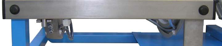
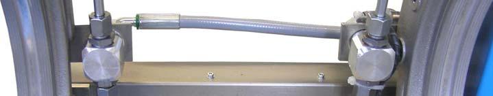
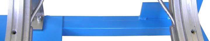
18 WIDOS Einsteinstr. 5 Phone Wilhelm Dommer Söhne D Ditzingen-Heimerdingen Fax GmbH Website: info@widos.de 5. Starting and operating The instructions of this chapter are supposed to initiate in the operation of the hydraulic control unit and lead during the appropriate starting of the hydraulic control unit. This includes: - The safe operation of the hydraulic control unit; - Using all the possible options of the hydraulic control unit; - Economic operation of the hydraulic control unit Safety indications The hydraulic control unit may only be operated by initiated and authorized persons. For the qualification, a plastic welding exam can be taken according to DVS and DVGW. After completion of the welding work and during breaks the hydraulic control unit has to be switched off. Further take care that no unauthorized person has access. According to VDE 0100, the use on construction sites is only allowed with a power distributor with a RCD (FI) security protective switch. Take care that all hydraulic and electric connections are connected Connecting the WI-CNC 1.1 / 1.3 to the welding machine Connect both hydraulic hoses of the basic machine with couplings (chapter: 4, no. 12 and 13). In case there is a basic machine with measuring system, connect it with the interface (9). Connect the plug of the WI-CNC 1.1 with a local socket (230V / 50 Hz /16 A) and the WI-CNC 1.1 with a local socktet (400V / 50 Hz / 3*16A) or on building sites to the current distributor with RSD (FI) safety switch. Connect the heating element with PLC system (optional) to the socket (11), or connect a heating element without PLC system to the socket (11) or an external socket. Connect the planer to the socket (15). Now the machine is ready Working Instructions WIDOS WI-CNC Page 18 of 89
19 Starting and operating Chapter Buttons on the touch screen Three variants are possible: Button dark: Button bright: Button bright, animated: Button inactive, cannot be operated Button active, for manual operation Indication for next operation Small buttons Abort Open, manually Diagnosis Welding process Information Yes (green) Copy Empty Minus Next section Next in: (insert pipes, clean them) No (red) Parameter Plus Checking off Checking on (black) Identify machine automatically, (option with digital displacement transducer) Back Close, manually Check oil level Next Working Instructions WIDOS WI-CNC Page 19 of 89


 active")
 not")

 Unclamp not")


20 Starting and operating Chapter Large buttons Cooling Keyboard (colored) active Aligning Keyboard (black) not activated Heating Joint number Move open O.K. (green) Unclamp not O.K. (red) Basic position Set parameters Drag pressure measuring Ramp, pressure build-up Check (black) Start Insert heating element Change over Check heating element temperature Alignment check Planer rotating Alignment check made, o.k. Insert planer Working Instructions WIDOS WI-CNC Page 20 of 89


!")

21 Starting and operating Chapter How to switch on the WI CNC 1.3 Open the flaps on the WI CNC 1.3 and switch on the main switch (chapter: 4, no.: 3). As soon as the switch is activated, the display gets bright, the processor is being initialized and the display messages change automatically. Indication of current software version, serial number and free memory space: 183 = free weldings in the RAM (max. appr. 200 memory capacities) / 31,830 memory capacities available at USB Display: validity period until next service, and operator identification Before entering the 4-digit login name, the machine is depressurized. Only now you can check the oil level (chapter: 6.4)! Either: Authorize yourself with (optional) scanner and corresponding barcode from the authorization card. Or: Press: < > and enter a four-digit login name via keyboard. Then press button < >. If you press button < > it appears: Confirm the message with < > Working Instructions WIDOS WI-CNC Page 21 of 89


22 Starting and operating Chapter 5 Enter a four-digit code using the keypad. Confirm the code with button < >. Basic menu: Indication of serial numbers of the connected devices 1104 = free weldings in the RAM / max. appr memory capacities on USB (or: = no memory possible on USB) Display of operator identification In the basic menu you can: Either: Move the basic machine open, therefore press button: < >. Or: Identify the basic machine type with button: < > Select machine type with way measurement system Display of software version Display of serial numbers Display: validity period until next service, Press button < >, the machine is identified automatically Working Instructions WIDOS WI-CNC Page 22 of 89


23 Starting and operating Chapter 5 This error message appears if no position measuring system is available and basic machine is not connected. Error message always appears once no travel sensor is available, or error message appears if pipes are clamped. Confirm the error message with button: < >. Press: < > in order to identify the machine manually. Indication of all machine types, the selected machine type is highlighted. Confirm the selected machine with button: < >. Indication of all machine types, the selected machine type is highlighted Working Instructions WIDOS WI-CNC Page 23 of 89


24 Starting and operating Chapter 5 Press button: < > for automatically identifying of basic machine. Machine moves in basic position. Main menu, Error message: way measuring system missing Error message: heating element missing You can: Select dimensions with: < > Open basic machine with: < > Close basic machine with: < > Select machine type without way measurement system This message only appears when you first turn: Indication of serial numbers of the connected devices Display of the machine type Confirm the error message with button: < >. Indication of all machine types, the selected machine type is highlighted Working Instructions WIDOS WI-CNC Page 24 of 89


25 Starting and operating Chapter 5 Tap on the machine type you want to weld with. Confirm your choice with the < > button Indication of the connected slide Confirm the selected machine type with butto n: < >. Indication of the connected slide Press button: < > to move the machine in basic position. Main menu, Error message: way measuring system missing Error message: heating element missing You can: Select dimensions with: < > Open basic machine with: < > Close basic machine with: < > Working Instructions WIDOS WI-CNC Page 25 of 89


26 Starting and operating Chapter How to determine the dimension Main menu, Error message: way measuring system missing Error message: heating element missing You can: Select dimensions with: < > Open basic machine with: < > Close basic machine with: < > Press button: < > for selecting the dimensions. Image only appears once you press: < >: Scroll text with < >, it is explained on the screen. By pressing < again. > you will leave the explanation menu Current dimensions are displayed Select material PE / PP / SLM30 with left buttons: < / >. Select outer diameter for pipe with the second buttons: < / >. Select the wall thickness with the third buttons: < / >, then the SDR size is displayed automatically. The temperature is displayed according to DVS rule, cannot be changed. Select method DVS / ProFuse / WIS / ASTM / NEN with button < > Working Instructions WIDOS WI-CNC Page 26 of 89


27 Starting and operating Chapter 5 Die ausgesuchte Schweißstandard wird markiert. Confirm the selected welding method with button < >. No = < >; Yes = < >; Either: Confirm the new method with button < >. Or: Press button < > and select the other method. Current dimensions are displayed Either: Confirm the selections with button < >. Or: press button: < > for other settings Working Instructions WIDOS WI-CNC Page 27 of 89
28 Starting and operating Chapter Further settings for traceability, ½ cooling time or entering RAM > USB Current dimensions are displayed Press button: < > for other settings. Press < > in order to select traceability, the button changes to: < >. Press < > in order to select ½ cooling time, the button changes to: < >. Press < > in order to copy all existing weldings from the RAM to the connected device at the USB interface. Either: Terminate all further settings with < >. Or: Enter the diagnosis menu with < >. Or: Press: < > for further settings: clock, date and signal horn Working Instructions WIDOS WI-CNC Page 28 of 89


29 Starting and operating Chapter How to adjust date, time, signal horn and language Press button: < > for other settings. Different languages are indicated, by selecting a language it is highlighted. Volume: Tap the volume bar depending on the volume, the volume bar will be refreshed, or tap < > in order to disable the signal horn, then: < > appears. Language: Tap the desired language, the language is highlighted. Clock + Date: Press < > in order to select clock and date adjustment. Date and time is displayed Adjust: day, month and year as well as hour and minute with: < / >. Confirm it with button < > Working Instructions WIDOS WI-CNC Page 29 of 89

30 Starting and operating Chapter 5 Different languages are displayed, by selecting a language it is highlighted. Confirm it with button < >. Current machine is displayed Current date and time is displayed Working Instructions WIDOS WI-CNC Page 30 of 89
31 Starting and operating Chapter Welding with the WI CNC 1.1 / 1.3 Activate the WI CNC 1.1 / 1.3 (chapter: 5.4), and identify the basic machine (chapter: or 5.4.2). Current machine is displayed Current date and time are displayed. Press button: < > for the start of welding process. If you have a basic machine without way measurement system, this error message will appear: Confirm the error message with button < >. If you have not driven the basic machine back into basic position when activating, this error message appears: Confirm the error message with button < > Working Instructions WIDOS WI-CNC Page 31 of 89


32 Starting and operating Chapter 5 Current machine is displayed Current date and time are displayed. Then go back with < will be possible. > and drive the machine to basic position, otherwise no welding Current dimensions are displayed Check the dimensions whether they match the pipes. Confirm the settings with < >. Select the current weather on the left side. Select the weather protections on the right side and carry out the measures on the machine. Either: Confirm the settings with < >. Or Confirm the settings with < >. Then the last project name and the next joint number are recorded automatically. Then continue with: (page: 36) Working Instructions WIDOS WI-CNC Page 32 of 89


33 Starting and operating Chapter 5 Display: - current job name number 1. - current job name Either: Change the indicated job name via keyboard. Or: Press < >, then you can select job name numbers 2 5 and use or change them if necessary. Display: - current job name number 3. - current job name Confirm the selected job name with < >. Display: - current joint number is stored related to the project. You can change the joint number via keyboard, the counter continues automatically for the next welding. Confirm the joint number with < > Working Instructions WIDOS WI-CNC Page 33 of 89


 If necessary you can open / close the basic machine with buttons < / >.")

34 Starting and operating Chapter 5 If you have connected a heating element with PLC function and if the current temperature has not yet reached the nominal temperature, the display shows: Display: Pipe dimension, time + outside temperature Indication of nominal temperature (orange) and current temperature (red) Confirm error message with button < >. Display: Pipe dimension, time + outside temperature Indication of nominal temperature (orange) and current temperature (red) If necessary you can open / close the basic machine with buttons < / >. Once the heating element has heated up to nominal temperature, the display shows: Display: Pipe dimension, time + outside temperature Indication of nominal temperature (orange) and current temperature (red) If necessary you can open / close the basic machine with buttons < / >. Press the (blinking) button < > Working Instructions WIDOS WI-CNC Page 34 of 89

35 Starting and operating Chapter 5 This message appears only if a manual heating element is available resp. if the heating element is not connected to the WI CNC 1.3. Display: Pipe dimension, time + outside temperature Indication of nominal and current temperature Confirm the error message with button < >. Display: Pipe dimension, time + outside temperature Indication of nominal temperature (orange) and current temperature (red) If necessary you can open / close the basic machine with buttons < / >. Press button < > for setting temperature. Indication of the heating element temperature manually adjusted Enter the heating element temperature with: < / > that you have adjusted at the manual heating element; it should match the nominal temperature. Confirm temperature with < >. Display: Pipe dimension, time + outside temperature Indication of nominal temperature (orange) and current temperature (red) If necessary you can open / close the basic machine with buttons < / > Working Instructions WIDOS WI-CNC Page 35 of 89


36 Starting and operating Chapter 5 Check the current temperature at the manual heating element if it has been reached and press the (blinking) button < > afterwards. This message appears only if the basic machine is not completely open: Display: Pipe dimension, time + outside temperature Display: nominal pressure: ps, motion pressure: p0, current pressure: pi and current temperature Press < > in order to open the basic machine completely. Display: Pipe dimension, time + outside temperature Display: nominal pressure: ps, motion pressure: p0, current pressure: pi and current temperature Fix the pipes in the clamping rings and clean the pipe ends. Confirm with < >. Display: Pipe dimension, time + outside temperature Display: nominal pressure: ps, motion pressure: p0, current pressure: pi and current temperature Press < > in order to start motion pressure measuring Working Instructions WIDOS WI-CNC Page 36 of 89


37 Starting and operating Chapter 5 Display: Pipe dimension, time + outside temperature Display: nominal pressure: ps, motion pressure: p0, current pressure: pi and current temperature The motion pressure is being measured, afterwards this message appears automatically: In case you have clamped the pipes too far in, this message appears: Display: Pipe dimension, time + outside temperature Confirm the error message with < >. Afterwards release the clamping rings and clamp one or both pipes farther out. Display: Pipe dimension, time + outside temperature Display: nominal pressure: ps, motion pressure: p0, current pressure: pi and current temperature Press < > in order to start motion pressure measuring Working Instructions WIDOS WI-CNC Page 37 of 89


38 Starting and operating Chapter 5 Display: Pipe dimension, time + outside temperature Display: nominal pressure: ps, motion pressure: p0, current pressure: pi and current temperature The machine is being calibrated, afterwards this message appears automatically: Insert the planer into the machine in-between the pipe ends and let it snap in the front. For starting rotation of the planer press button < > and keep it pressed. Display: Pipe dimension, time + outside temperature Display: nominal pressure: ps, motion pressure: p0, current pressure: pi and current temperature Cut the pipe ends until a circular chip has formed running around the pipe ends 2-3 times and < > is blinking. Then release < > Working Instructions WIDOS WI-CNC Page 38 of 89

39 Starting and operating Chapter 5 Display: Pipe dimension, time + outside temperature Display: nominal pressure: ps, motion pressure: p0, current pressure: pi and current temperature Unlock the planer, take it out of the machine and put it into the reception box. Remove the chips created, thereby do not touch the prepared surfaces. Either: The pipe ends are plane; then press < > in order to start mismatch checkup; the machine moves the pipes ends together. Or: The pipe ends are not plane; then reinsert the planer into the basic machine and start planing with < >. Display: Pipe dimension, time + outside temperature Display: nominal pressure: ps, motion pressure: p0, current pressure: pi and current temperature Check mismatch at the abutting pipe ends; mismatch must not exceed 10% of the wall thickness according to DVS. The gap must not exceed 0.5 mm for pipes with OD 355 mm and 1.0 mm for pipes with OD mm. In case the mismatch is not correct, you can compensate a mismatch by changing the clamping of the pipes; afterwards necessarily repeat planing with: < >. In case the mismatch is correct, then you can: Either: Continue welding with < >, Working Instructions WIDOS WI-CNC Page 39 of 89


40 Starting and operating Chapter 5 Or: Carry out a test pressure with: < > in order to check the slipping of the pipes. Display: pipe dimension, time + outside temperature Display: nominal pressure: ps, motion pressure: p0, current pressure: pi and current temperature Or: Keep < > pressed; the machine will build up the pressure. Simultaneously check nominal and current pressure. The pipes are slipping at a current pressure nominal pressure; then you must increase the clamping of the pipes and repeat planing with < >. This message appears only if machine has a GPS receiver (optional) Display: pipe dimension, time + outside temperature Display: nominal pressure: ps, motion pressure: p0, current pressure: pi and current temperature Current GPS coordinates are indicated. Display: pipe dimension, time + outside temperature Display: nominal pressure: ps, motion pressure: p0, current pressure: pi and current temperature Insert the heating element into the machine and confirm it with < > Working Instructions WIDOS WI-CNC Page 40 of 89


41 Starting and operating Chapter 5 Display: Pipe dimension, time + outside temperature Display: nominal pressure: ps, motion pressure: p0, current pressure: pi and current temperature Bead up [mm] is indicated. In case you are welding with a basic machine without way measurement system, this message appears: Display: Pipe dimension, time + outside temperature Display: nominal pressure: ps, motion pressure: p0, current pressure: pi and current temperature Visually check the bead up. Once the bead up is completed, you can take the corresponding value from the welding table of the manual machine, press < start heating. >. This will Once the bead up is completed, pressure is reduced and heating starts. Display: pipe dimension, time + outside temperature Display: nominal pressure: ps, motion pressure: p0, current pressure: pi and current temperature The elapsed heating time [s] is indicated. The end of the heating time is signaled by beeps; the display shows: Working Instructions WIDOS WI-CNC Page 41 of 89


42 Starting and operating Chapter 5 Display: Pipe dimension, time + outside temperature Display: nominal pressure: ps, motion pressure: p0, current pressure: pi and current temperature The elapsed change over time [s] is indicated. Either: The machine opens. You remove the heating element from the machine within change over putting it into the reception box. Or: You do not remove the heating element within change over; then this message appears: Confirm the error message with < >; welding is aborted. Display: machine type Display: date and time Display: user name The machine will move the pipes together after change over Working Instructions WIDOS WI-CNC Page 42 of 89


43 Starting and operating Chapter 5 Display: Pipe dimension, time + outside temperature Display: nominal pressure: ps, motion pressure: p0, current pressure: pi and current temperature The elapsed cooling time [min] is indicated. Message appears only if welding is not correct: Display: Pipe dimension, time + outside temperature Display: nominal pressure: ps, motion pressure: p0, current pressure: pi and current temperature Error during welding is indicated. Confirm the error message with < >. Display: pipe dimension, time + outside temperature Display: nominal pressure: ps, motion pressure: p0, current pressure: pi and current temperature Incorrect welding is indicated. Release the clamping rings and remove the welded pipe from the basic machine. Confirm the error message with < >. In case welding is correct, this message appears automatically: Working Instructions WIDOS WI-CNC Page 43 of 89


44 Starting and operating Chapter 5 Display: Pipe dimension, time + outside temperature Display: nominal pressure: ps, motion pressure: p0, current pressure: pi and current temperature Display: welding parameter correct Release the clamping rings and remove the welded pipe from the basic machine. Confirm removal of the welded pipe with < >. Display: machine type Display: date and time Display: user name Welding is completed Working Instructions WIDOS WI-CNC Page 44 of 89
 Connect the")
. Current dimension is indicated Press < > for other settings.")


45 Starting and operating Chapter Copy internal data onto SD card and delete internal data (RAM) Connect the USB stick or any other memory medium to one of the USB interfaces (chapter: 4, no. 4). Current dimension is indicated Press < > for other settings. Press < > in order to copy all existing weldings from the RAM onto the connected device at the USB interface. In case no stick / memory medium is connected to a USB interface; this message appears: Plug the stick / memory medium into a USB interface and confirm the error message with < > Working Instructions WIDOS WI-CNC Page 45 of 89


46 Starting and operating Chapter 5 In case no welding is stored in the RAM; this message appears: Confirm the error message with < >. No = < >; Yes = < > Either: Press < > and delete the RAM memory. Or: Press < > and do not delete the RAM memory Working Instructions WIDOS WI-CNC Page 46 of 89
47 WIDOS Einsteinstr. 5 Phone Wilhelm Dommer Söhne D Ditzingen-Heimerdingen Fax GmbH Website: info@widos.de 6. Equipment care / maintenance / repair Goal of the chapter is: Keeping the nominal state and the operation capacity of the apparatus. Increasing the efficiency by avoiding non-planned outage. Efficient planning of the maintenance work and the maintenance tools Maintenance and inspection, repair All maintenance and repair work has to be basically performed with the apparatus in off position. During this the apparatus has to be secured against unauthorized switching on. Prescribed maintenance and inspection work should be performed in time. The DVS gives the advice of inspection work after 1 year. Validity of the current maintenance will be indicated on the screen after activation: The work should be performed at the WIDOS GmbH company or by an authorized partner. The operating staff has to be informed before the starting of the maintenance work. Check the tightness of all screwed connections. Check the function of the safety devices after completion of the maintenance work How to clean the operator panel (touch screen) Clean the operator panel regularly and proceed as follows: Activate the machine. Spray some cleaning agent onto the cleaning cloth. Do not spray directly onto the operator panel. Clean the operator panel. Wipe the cloth from the edge of the screen to the inside in case you clean the display. Only clean the operator panel after you have switched it off. By this, you can be sure not to activate functions unintentionally while touching the keys. Do not clean the operator panel using compressed air or steam cleaners. Never use any solvents or abrasives. Use a wet cleaning cloth with cleaning agent. As cleaning agents, please only use flush fluid or foaming cleaning agents for photos Working Instructions WIDOS WI-CNC Page 47 of 89

48 Equipment care / maintenance / repair Chapter Cleaning of the hydraulic control unit The used materials and tissues are to be handled and disposed of properly, especially when cleaning with solvents. when lubricating with oil and grease Check oil level Check oil level only at the following indication: Either: This indication appears automatically after activation of the WI-CNC , Or: Step back with: < > while the device is activated and authorized. Put the WI-CNC 1.3 on even ground. Pull out the oil dipstick at the side of the WI-CNC Wipe the oil dipstick with a dry cloth, put it back into the tank and pull it out again. Read the oil level; it must be in-between both markings. Markings In case the oil level is below the lower marking; you must refill with hydraulic oil HLPD 32. Put the oil dipstick back into the device after checking until the lock snaps in Used hydraulic oil Only use HLPD 32. Features: protection against corrosion, resistance to ageing, abrasion-reducing additives, high carrying capacity and particularly water repellent. The hydraulic oil has to be handled properly and to be disposed of Storage Store the hydraulic control unit in a dry room Disposal At the end of their life time, the apparatus and the wear parts have to be disposed of properly and non-polluting, and in accordance with the national laws of waste disposal Working Instructions WIDOS WI-CNC Page 48 of 89
49 WIDOS Einsteinstr. 5 Phone Wilhelm Dommer Söhne D Ditzingen-Heimerdingen Fax GmbH Website: info@widos.de 7. Transport The WI-CNC is transported together with the welding machine in a transport box. The transport box is more suitable for longer transports. Make sure that the device is not tilted too much in order that oil cannot leak out. Protect the hydraulic control unit from heavy shocks. Make sure that the box cover is closed correctly. During the construction of the transport box a stress was put on a light-weight construction. Take much care when using automatic handling and carrying machines Working Instructions WIDOS WI-CNC Page 49 of 89

50 WIDOS Einsteinstr. 5 Phone Wilhelm Dommer Söhne D Ditzingen-Heimerdingen Fax GmbH Website: info@widos.de 8. Circuit diagrams 8.1. Circuit diagrams for WI-CNC Working Instructions WIDOS WI-CNC Page 50 of 89
51 Circuit diagrams Chapter Working Instructions WIDOS WI-CNC Page 51 of 89
52 Circuit diagrams Chapter Working Instructions WIDOS WI-CNC Page 52 of 89
53 Circuit diagrams Chapter Working Instructions WIDOS WI-CNC Page 53 of 89
54 Circuit diagrams Chapter Working Instructions WIDOS WI-CNC Page 54 of 89
55 Circuit diagrams Chapter Working Instructions WIDOS WI-CNC Page 55 of 89
56 Circuit diagrams Chapter Working Instructions WIDOS WI-CNC Page 56 of 89

57 Circuit diagrams Chapter Working Instructions WIDOS WI-CNC Page 57 of 89
58 Circuit diagrams Chapter Working Instructions WIDOS WI-CNC Page 58 of 89
59 Circuit diagrams Chapter Working Instructions WIDOS WI-CNC Page 59 of 89

60 Circuit diagrams Chapter Working Instructions WIDOS WI-CNC Page 60 of 89
61 Circuit diagrams Chapter Working Instructions WIDOS WI-CNC Page 61 of 89
62 Circuit diagrams Chapter Circuit diagrams for WI-CNC Working Instructions WIDOS WI-CNC Page 62 of 89
63 Circuit diagrams Chapter Working Instructions WIDOS WI-CNC Page 63 of 89
64 Circuit diagrams Chapter Working Instructions WIDOS WI-CNC Page 64 of 89
65 Circuit diagrams Chapter Working Instructions WIDOS WI-CNC Page 65 of 89
66 Circuit diagrams Chapter Working Instructions WIDOS WI-CNC Page 66 of 89
67 Circuit diagrams Chapter Working Instructions WIDOS WI-CNC Page 67 of 89
68 Circuit diagrams Chapter Working Instructions WIDOS WI-CNC Page 68 of 89
69 Circuit diagrams Chapter Working Instructions WIDOS WI-CNC Page 69 of 89
70 Circuit diagrams Chapter Working Instructions WIDOS WI-CNC Page 70 of 89
71 Circuit diagrams Chapter Working Instructions WIDOS WI-CNC Page 71 of 89

72 Circuit diagrams Chapter Working Instructions WIDOS WI-CNC Page 72 of 89
73 Circuit diagrams Chapter Working Instructions WIDOS WI-CNC Page 73 of 89


74 WIDOS Einsteinstr. 5 Phone Wilhelm Dommer Söhne D Ditzingen-Heimerdingen Fax GmbH Website: info@widos.de 9. Spare parts list 9.1. Hydraulic control unit WI-CNC Working Instructions WIDOS WI-CNC Page 74 of 89
75 Spare parts list Chapter 9 WI-CNC control unit 1.1 Pos. Name Piece Order no. 1 Cover Threaded rod M5 DIN mm 0975E 3 Hexagon domed cap nut M 5 DIN E 4 Plastic washer M EK 5 Main switch 1 ES Buit-in socket USB 2 ES Hood Lens-head screw M 6x16 DIN F012 9 Cover Threaded rod M5 DIN mm 0975E 11 Buzzer 1 ES Mounting case HAH 3A-AGG-QB 1 EST Socket insert 4 pole+pe 1 EST Cap 1 EST Outside temperature sensor 1 EE04040E 16 Socket 2 EST Coupling box, flat packing 1 VST14 18 Coupling plug, flat packing 1 VMU14 19 Connection cable with plug 1 EK GPS-receiver (optional) 1 EG Plug for oil filler Working instructions WIDOS WI-CNC Page 75 of 89


76 Spare parts list Chapter Hydraulic control unit WI-CNC Working Instructions WIDOS WI-CNC Page 76 of 89
77 Spare parts list Chapter 9 WI-CNC control unit 1.3 Pos. Name Piece Order no. 1 Cover Threaded rod M5 DIN mm 0975E 3 Hexagon domed cap nut M 5 DIN E 4 Plastic washer M EK 5 Buit-in socket USB 2 ES Main switch 1 ES Hood Lens-head screw M 6x16 DIN F012 9 Cover Threaded rod M5 DIN mm 0975E 11 Buzzer 1 ES Mounting case HAH 3A-AGG-QB 1 EST Socket insert 4 pole+pe 1 EST Cap 1 EST Outside temperature sensor 1 EE04040E 16 CEE-electrical socket 400V / 16 A 2 EST16EG 17 Coupling box, flat packing 1 VST14 18 Coupling plug, flat packing 1 VMU14 19 Socket 2 EST Connecting cable 5x1,5 mm², 7 m 1 EL Plug 16 A 1 EST GPS-receiver (optional) 1 EG Plug for oil filler Working instructions WIDOS WI-CNC Page 77 of 89


")


78 Spare parts list Chapter Way measuring systems Way measuring system for WIDOS 6113: Cable with plug for all machines (10) Working Instructions WIDOS WI-CNC Page 78 of 89
79 Spare parts list Chapter 9 Way measuring system for WIDOS 6100: Working Instructions WIDOS WI-CNC Page 79 of 89
80 Spare parts list Chapter 9 Way measuring system for WIDOS 5500: Working Instructions WIDOS WI-CNC Page 80 of 89
81 Spare parts list Chapter 9 Way measuring-system for WIDOS 5100: Working Instructions WIDOS WI-CNC Page 81 of 89


82 Spare parts list Chapter 9 Way measuring-system for WIDOS 4900: Working Instructions WIDOS WI-CNC Page 82 of 89


83 Spare parts list Chapter 9 Way measuring-system for WIDOS 4600: Working Instructions WIDOS WI-CNC Page 83 of 89


84 Spare parts list Chapter 9 Way measuring-system for WIDOS 4400: / / Working Instructions WIDOS WI-CNC Page 84 of 89
85 Spare parts list Chapter 9 Way measuring systems WIDOS Pos. Name Piece Order no. 1 Pan-head screw M 3x6 DIN (5) (4) 0912C006 2 Washer M 3 DIN (5) (4) 0125C 3 Cover for magnetic tape (6113) (3) Cover for magnetic tape (6100) (3) Cover for magnetic tape (4600, 4900, 5100, 5500) (3) Cover for magnetic tape (4400) Magnetic tape (6113) 0,51 m EE07351 (4) Magnetic tape (6100) 0,41 m EE07351 (4) Magnetic tape (4600, 4900, 5100, 5500) 0,31 m EE07351 (4) Magnetic tape (4400) 0,21 m EE Cladding tube (6113) (5) Cladding tube (6100) (5) Cladding tube (5100, 5500) (5) Cladding tube (4900) (5) Cladding tube (4600) (5) Cladding tube (4400) Protective cap 40 x 40 2 J Cap around GL 20 x 1,2 2 J Pan-head screw M 8x16 DIN (1) 0912H016 9 Sliding piece Magnetic probe with cable, digital ( ) 1 EE0727 (10) Magnetic probe with cable, digital ( ) 1 EE Pan-head screw M 3x35 DIN C Washer M 3 DIN C 13 Hexagon nut M 3 DIN C 14 Plastic spiral KW 6 0,31 m EA Skintop screw ST - M 12 x 1,5 1 EV Driving pin Driving fork (6113) (17) Driving fork (6100) (17) Driving fork (5100) (17) Driving fork ( ) (17) Driving fork (4400) Pan-head screw M 8x16 DIN F Washer M 8 DIN F 20 Bending protection spiral M 12 black 1 EV Reduzer M20/M12 1 EV Socket shell M 20 1 EST Pin insert 4 pole+pe 1 EST Hexagon nut M 8 DIN H 25 Washer M 8 DIN H Working instructions WIDOS WI-CNC Page 85 / 1 of 89
86 Spare parts list Chapter 9 Way measuring systems WIDOS Pos. Name Piece Order no. 26 Support (4900) (26) Support (4600) (26) Support (4400) Pna-head screw M 6 x 16 DIN F Washer M 6 DIN F 29 Pan-head screw M 8x35 DIN F Distance bush Working instructions WIDOS WI-CNC Page 85 / 2 of 89


87 Spare parts list Chapter Heating elements with PLC-function Heating element control digital for machines Heating element control analog for machines Heating element control for machine Working Instructions WIDOS WI-CNC Page 86 of 89

88 Spare parts list Chapter 9 Heating element control for machine Working Instructions WIDOS WI-CNC Page 87 of 89
Working Instructions Translation
 WIDOS Einsteinstr. 5 Phone +49 (0) 71 52 99 39-0 W. Dommer Söhne GmbH D-71254 Ditzingen-Heimerdingen Fax +49 (0) 71 52 99 39-40 Website: www.widos.de Email: info@widos.de Working Instructions Translation
Working Instructions Translation
 WIDOS Einsteinstr. 5 Phone +49 (0) 71 52 99 39-0 W. Dommer Söhne GmbH D-71254 Ditzingen-Heimerdingen Fax +49 (0) 71 52 99 39-40 Website: www.widos.de Email: info@widos.de Working Instructions Translation
Working Instructions Translation
 WIDOS Einsteinstr. 5 Phone ++49 (0)7152 / 9939-0 W. Dommer Söhne GmbH D-71254 Ditzingen-Heimerdingen Fax ++49 (0)7152 / 9939-40 website: www.widos.de email: info@widos.de Working Instructions Translation
Working Instructions Translation
 WIDOS Einsteinstr. 5 Phone ++49 (0) 7152 9939-0 W. Dommer Söhne GmbH D-71254 Ditzingen-Heimerdingen Fax ++49 (0) 7152 9939-40 website: www.widos.de email: info@widos.de Working Instructions Translation
Working Instructions Translation
 WIDOS Einsteinstr. 5 Phone ++49 7152 9939-0 W. Dommer Söhne GmbH D-71254 Ditzingen-Heimerdingen Fax ++49 7152 9939-40 website: http://www.widos.de email: info@widos.de Working Instructions Translation
SI AT A22. English. Printed: Doc-Nr: PUB / / 000 / 01
 SI AT A22 English 1 Information about the documentation 1.1 About this documentation Read this documentation before initial operation or use. This is a prerequisite for safe, trouble-free handling and
SI AT A22. English. Printed: Doc-Nr: PUB / / 000 / 03
 SI AT A22 English 1 Information about the documentation 1.1 About this documentation Read this documentation before initial operation or use. This is a prerequisite for safe, trouble-free handling and
KeContact P20. User manual
 KeContact P20 User manual Comments to this manual In this manual you will find warnings against possible dangerous situations. The used symbols apply to the following meanings:!! WARNING! Indicates a potentially
Operating manual. original operating manual. HDA eco Box 12/24V DC Automatic Dispenser. Translation of the. Item No.:
 Operating manual HDA eco Box 12/24V DC Automatic Dispenser Item No.: 110 500 900 Translation of the original operating manual Important! Copyright The operating manual is always to be read before commissioning
User Guide. Lubricus Lubrication System LUB-D1/LUB-D2/LUB-D3/LUB-D4 (24 VDC)
") User Guide Lubricus Lubrication System LUB-D1/LUB-D2/LUB-D3/LUB-D4 (24 VDC) version 04/2013 Content General Information 3 Warning 3 Scope of Supply 3 Overview 3 General safety details 4 Intended use 4
User Guide Lubricus Lubrication System LUB-D1/LUB-D2/LUB-D3/LUB-D4 (24 VDC) version 04/2013 Content General Information 3 Warning 3 Scope of Supply 3 Overview 3 General safety details 4 Intended use 4
Important instructions
 Operation manual Please read this manual, before starting the unit. It contains important notes on commissioning and handling. Keep these instructions for future reference. Be careful even if you pass
Control unit for Strip Thickness Gauges with nominal size setting by stepper motor Operating Instructions
 Control unit for Strip Thickness Gauges with nominal size setting by stepper motor FS4-PLC Operating Instructions FS4P-E1 erstellt am 15.4.2002 freigegeben am Bemerkungen Rev.1 Seiten: Name: Rietdorf Name:
Tension Meter. Edition FT 03.E. FT Series. Instruction Manual. Valid as of: Please keep the manual for future reference!
 Tension Meter FT Series S C H M I D T c o n t r o l i n s t r u m e n t s Edition FT 03.E Model FT Instruction Manual Valid as of: 01.09.2011 Please keep the manual for future reference! Contents 1 Warranty
Wind Power Inverter WINDY BOY 5000A/6000A
 Wind Power Inverter WINDY BOY 5000A/6000A User Manual WB5A-6A-BA-BEN114530 TBEN-WB50-60A Version 3.0 EN SMA Solar Technology AG Table of Contents Table of Contents 1 Information on this Manual.........................
HIGH TECH SECURES YOUR FUTURE SBA 1200 GB SUN BRAKE ANALYSER. Operating Manual
 HIGH TECH SECURES YOUR FUTURE SUN BRAKE ANALYSER Operating Manual 2 Operating Manual SUN BRAKE ANALYSER Copyright December 2009 Snap-on Equipment GmbH All rights reserved Part number: 2000618380 Rev: 3
Lumitester PD-30. Instruction Manual. Table of Contents
 Table of Contents Lumitester PD-30 Instruction Manual Thank you very much for purchasing the Lumitester PD-30. All of this Instruction Manual must be read before operation of this product for safe and
Installation manual wall-mounted distributor
 EN Installation manual wall-mounted distributor EN 60003233 Issue 11.2016 2016-14-11 Table of contents 1 About this manual 3 1.1 Structure of the warnings 3 1.2 Symbols used 4 1.3 Signal words used 4 2
HST-BL-2830MS & HST-BL-2830MS-USA
 HST-BL-2830MS & HST-BL-2830MS-USA Release date: 02/2017 High - System - Technik Im Martelacker 12 D-79588 Efringen-Kirchen Phone 0 76 28-91 11-0 Fax 0 76 28-91 11-90 E-Mail: info@hs-technik.com Web: www.hs-technik.com
Installation manual portable distributors
 EN Installation manual portable distributors EN 60003206 Issue 11.2016 15/11/2016 Table of contents 1 About this manual 3 1.1 Structure of the warnings 3 1.2 Symbols used 4 1.3 Signal words used 4 2 Intended
Rolli D6/5A. Operating Instructions HORN GMBH & CO. KG. Product Description. Safety Indications. Mounting. Commissioning.
 Declaration of Conformity Operating Instructions Rolli D6/5A 440209101-A 03/2004 Subject to technical alterations. Text and design copyrighted. Reprinting and copying, even if excerpts, only with written
MANUAL. Single charger
 MANUAL Single charger HST-PR-2830 & HST-PR-2830USA for HS-Technik batteries HST-PR-18xx HST-PR-14xx issue date: November 2016 Table of contents Page 1. Basic information...3 1.1. Purpose of this document...3
Instructions for Use Plain Trolley ULK Geared Trolley UHK
 Instructions for Use Plain Trolley Geared Trolley Item no. Load-carrying capacity (payload) Weight Trolley widths *special trolley widths* Device dimensions mm H / W / D Minimum curve radius mm -005 0,5
original operating manual Operating manual Translation of the Item-No.: ,
 Translation of the original operating manual Operating manual Item-No.: 015 431 551, 015 431 581 Important! Copyright The operating manual is always to be read before commissioning the equipment. No warranty
Heat Meter Integrator
 Heat Meter Integrator Features Simply operation Integral wall and DIN-rail mounting bracket Pulsed or M-Bus output options Measures heating or cooling and heat/cooling Specification Product Codes Temperature
Operating instructions ErgoPack 600 E
 Operating instructions ErgoPack 600 E Operation of the device is only permitted if the operating instructions have been carefully read and understood before use! Declaration of conformity EU declaration
A company of ThyssenKrupp Elevator. ThyssenKrupp Aufzugswerke. Operating Manual. Oil buffer
 A company of ThyssenKrupp Elevator ThyssenKrupp Aufzugswerke Operating Manual Oil buffer OPERATING MANUAL Printer s imprint All rights reserved. Copyright by: THYSSENKRUPP AUFZUGSWERKE GMBH P.O. box 23
Operator's Manual. Storage System. Ultrasound Probe Cabinet. Manufactured by:
 Storage System Ultrasound Probe Cabinet Operator's Manual Manufactured by: CIVCO Medical Solutions 102 First Street South Kalona, IA 52247 USA 319.248.6757 / 800.445.6741 WWW.CIVCO.COM Copyright 2018 All
HST -LS Interlocking device (Translation of Original Manual)
") Installation and Operating Manual for Components HST -LS Interlocking device (Translation of Original Manual) HST-LS Ident.-No.: 10268 HST-LS Ident.-No.: 10269 HST-LS, pictured Ident-Nr. 10269 The image
Installation and Operating Manual for Components HST -LS Interlocking device (Translation of Original Manual) HST-LS Ident.-No.: 10268 HST-LS Ident.-No.: 10269 HST-LS, pictured Ident-Nr. 10269 The image
Documentation. RM-BV4 Micro DP. Filter control
 Documentation RM-BV4 Micro DP Filter control Contents 1 Safety instructions... 3 2 Device description... 3 3 Installation... 4 4 Installation... 5 4.1 Connection of the differential pressure measuring
Pressure relief valve
 Pressure relief valve Operating manual Series DHV 712 Version BA-2015.10.20 EN Print-No. 300 510 TR MA DE Rev001 ASV Stübbe GmbH & Co. KG Hollwieser Straße 5 32602 Vlotho Germany Phone: +49 (0) 5733-799-0
ACROBAT SWING STAND MODEL
 Mounting instructions Directions for use ACROBAT SWING STAND MODEL Dr. Mach GmbH u. Co.KG, Flossmannstrasse 28, D-85560 Ebersberg Tel.: +49 (0)8092 2093 0, Fax +49 (0)8092 2093 50 Internet: www.dr-mach.com,
Operating Instructions
 Operating Instructions Lubricus Lubrication System LUB - M (24 VDC) Operating Instructions: LUB- M Table of Contents Contents 2 1) General Information 4 1.1 Warning 4 1.2 Scope of supply 4 1.3 Overview
SECTIONAL AND TILTING DOOR OPENER INSTALLATION INSTRUCTIONS AND USER GUIDE. Comfort 800E/1000E
 SECTIONAL AND TILTING DOOR OPENER INSTALLATION INSTRUCTIONS AND USER GUIDE Comfort 800E/1000E WARNING Please read the manual carefully before installation and use. The installation of your new door opener
Bosch Smart Home. Door/Window Contact Instruction Manual
 Bosch Smart Home Door/Window Contact Instruction Manual Start making your home smart! Please be sure to install the Bosch Smart Home Controller first. Please ensure that you have a Bosch Smart Home Controller
I. Safety precautions
 . Safety precautions The items described in these instructions and on the inverter itself are very important so that you can use the inverter safely, prevent injury to yourself and other people around
OPERATIONS MANUAL CR Thermoreactor
 OPERATIONS MANUAL CR 2200 Thermoreactor CR 2200 Note For the most recent version of the manual, please visit www.ysi.com. Contact Copyright YSI 1725 Brannum Lane Yellow Springs, OH 45387 USA Tel: +1 937-767-7241
HXE4B BATTERY POWERED CRIMP TOOL
 Description The HXE4B Battery Powered Crimp Tool is a hand held, self contained crimp tool intended to crimp copper and aluminum cable with DMC Y dies. Safety Safety is essential in the use and maintenance
Instrucciones de instalación y funcionamiento Installation and operating instructions
 Wilo-ElectronicControl D Einbau- und Betriebsanleitung E Instrucciones de instalación y funcionamiento GB Installation and operating instructions I Istruzioni di montaggio, uso e manutenzione F Notice
Inlet Controller TC5-ITA USER'S MANUAL. M rev. 02 K rev. 00
 Inlet Controller TC5-ITA USER'S MANUAL M 890-00047 rev. 02 K 895-00458 rev. 00 TABLE OF CONTENTS PRECAUTIONS... 3 FEATURES... 4 LOCATION OF THE CONTROLS... 5 Status Leds...5 Internal Switches...6 INSTALLATION
Type MZ15. Operating Instructions. Bedienungsanleitung Manuel d utilisation
 Handheld calibration tool / Handheld cleaning tool Tragbares Kalibrierwerkzeug / Tragbares Reinigungswerkzeug Outil d'étalonnage portatif / Outil de nettoyage portatif Operating Instructions Bedienungsanleitung
Electronic Park Brake, Service & Reset Tool. User Guide
 30662000 Electronic Park Brake, Service & Reset Tool User Guide Produced by the Manufacturer All rights reserved. This publication may not be reproduced, in full or in part, without the express written
OPERATING MANUAL. A5 MIG Orbital System
 EN 1920360 A5 MIG Orbital System 1500 CONTENTS 1. Introduction...3 1.1 General...3 1.2 About the product...4 1.3 Compatibility...4 2. Installation...5 2.1 Connecting to a FastMig welding machine...5 2.2
Extended Panel Operation Manual RKP001Z-0
 Extended Panel Operation Manual RKP001Z-0 Table of Contents 1. NAMES AND FUNCTIONS OF MAIN PARTS...3 2. CONNECTION AND START-UP...4 3. DIMENSIONS...5 4. PROTECTION FUNCTION...6 5. SPECIFICATIONS...6 6.
Module B Module C FOR THE WEATHER CONTROLLER MULTI-MIX INSTALLATION MANUAL REVISION: 1.0_EN
 Module B Module C FOR THE WEATHER CONTROLLER MULTI-MIX INSTALLATION MANUAL REVISION: 1.0_EN 05-2018 ELECTRIC DEVICE UNDER VOLTAGE! Before any action related to the power supply (cables connection, device
Original Operating Manual
 2010-10-29 Original Operating Manual Control Panel Comfort for Pedelecs Series 4313 Save for future use! Marquardt GmbH Schlossstraße 16 78604 Rietheim-Weilheim E-mail: marquardt@marquardt.de Website:
Operating instruction and technical description
 Operating instruction and technical description EV Simulator for charging devices with charging plug / charging coupler / charging cable type 1 and type 2 as service case Photo: EV simulator/tester with
F-4600 INLINE ULTRASONIC FLOW METER Installation and Operation Guide
 F-4600 INLINE ULTRASONIC FLOW METER Installation and Operation Guide 11451 Belcher Road South, Largo, FL 33773 USA Tel +1 (727) 447-6140 Fax +1 (727) 442-5699 1054-7 / 34405 www.onicon.com sales@onicon.com
ON SAFEGUARD S ON SAFEGUARD M
 instructions Retrofit option GB ON SAFEGUARD S ON SAFEGUARD M Insulating protective cover Observe additional system documents! General instructions CAUTION Read the operating instructions! The operating
Turbocharger / VTR..0, VTR..1 Original assembly instructions English
 Assembly Instructions Turbocharger / VTR..0, VTR..1 Original assembly instructions English This document is valid for the VTR..0/..1 series: VTR160, VTR200, VTR250, VTR320, VTR400 VTR161, VTR201, VTR251,
INSTALLER MANUAL USER MANUAL. Contents
 Installation & user manual two way Contents INSTALLER MANUAL Important information General 1. Technical data 2. Description Installation: 1. Positioning the unit 2. Connection. 3. Parts description. 4.
Compact Heat Meters. Features. -A Pulsed output. -B M-Bus output. Accessories. UK Sales Tel: International Tel:
 Compact Heat Meters Features Compact design Simple operation Pulsed output Measures heating or cooling Specification Product Codes Water Meter Temp. range 10 to 90 C Nominal pressure 16bar Installation
Technical Documentation
 Technical Documentation Product manual Holding brake controller Document: 0198441113316 Edition: V1.00, 03.2006 Important information The drive systems described here are products for general use that
Original Operating Manual
 matev GmbH Nürnberger Str. 50 90579 Langenzenn T +49 (0) 9101 9087-0 F +49 (0) 9101 9087-20 info@matev.eu www.matev.eu Original Operating Manual Snow blade SRM-FB 120 CD Angle adjustment mechanical Version
Operating instructions. sonnenprotect for operators. KD-337 Part no Version X00.
 Operating instructions for operators sonnenprotect 1300 KD-337 Part no. 22010 Version X00 info@sonnenbatterie.de www.sonnenbatterie.de EN IMPORTANT Read this documentation carefully before operation. Retain
DC Master 24/ A
 USERS MANUAL DC Master 24/12 50-60A DC-DC converter MASTERVOLT Snijdersbergweg 93, 1105 AN Amsterdam The Netherlands Tel.: +31-20-3422100 Fax.: +31-20-6971006 www.mastervolt.com ENGLISH Copyright 2015
8.50 Kampmann Equestrian Solarium Perfect Enhances the Vital Functions and the Immune System Table of Contents.
 1.26 1.45 8.50 Kampmann Equestrian Solarium Perfect Table of Contents Table of Contents 1.26 1.46 1. Correct and Proper Use.......................................... 3 1.1 Personal Qualification 1.2 Limits
Installation and Operating Manual for Tank and Equipment Cleaning Nozzles Series 5TM
 Installation and Operating Manual for Tank and Equipment Cleaning Nozzles Series 5TM 150 150 150 This instruction manual contains proprietary information which is protected by copyright laws. No part of
Installation and user manual. 5SC 500i 5SC 750i 5SC 1000i 5SC 1500i ENGLISH. Copyright 2013 EATON All rights reserved.
 ENGLISH Installation and user manual 5SC 500i 5SC 750i 5SC 1000i 5SC 1500i Copyright 2013 EATON All rights reserved. Service and support: Call your local service representative Certification Standards
Installation and operating instructions. Solar charge controller MPPT 10 A / 20 A Z Z
 Installation and operating instructions Solar charge controller MPPT 10 A / 20 A EN 1 Contents 1. About these instructions... 3 1.1 Applicability... 3 1.2 Users... 3 1.3 Description of symbols... 3 2.
Operating instructions
 Operating instructions Digital tank contents indicator DTA 10 DTA 10 DTA 10 0 4.0 m fuel oil 0 3.5 m water Read instructions before using device! Observe all safety information! Keep instructions for future
Megohmmeter Test Probe
 Megohmmeter Test Probe User Manual ENGLISH www.aemc.com CHAUVIN ARNOUX GROUP Copyright Chauvin Arnoux, Inc. d.b.a. AEMC Instruments. All rights reserved. No part of this documentation may be reproduced
OPERATING MANUAL LA-BO. Applicator
 OPERATING MANUAL LA-BO Applicator Release 3-4/2017 Content General Notes & Safety Instructions -5 General notes -5 Validity and binding effect of this manual -5 Illustrations and descriptions -6 Safety
Compensation unit AGE-XY 50-80
 Translation of the origninal manual Compensation unit AGE-XY 50-80 Assembly and operating manual Superior Clamping and Gripping Imprint Imprint Copyright: This manual remains the copyrighted property of
ENGLISH SAFETY INSTRUCTIONS. Recommendations for safe operation. Operator safety. General warnings
 Safety and use instructions LifeSpeed iq TM - 3-phase chargers ENGLISH SAFETY INSTRUCTIONS GOALS OF THIS MANUAL This manual is aimed at any authorized personnel wanting to use a 3-phase LifeSpeed iq TM
VARIFUEL MAINTENANCE AND REPAIR INSTRUCTIONS
 VARIFUEL2 200-120 MAINTENANCE AND REPAIR INSTRUCTIONS MOTORTECH Gas Regulation P/N 01.50.008-200-120-EN Rev. 06/2015 Copyright Copyright 2015 MOTORTECH GmbH. All rights reserved. Distribution and reproduction
Operating manual. High-voltage testing adapter VAS 6558A/30. Operating manual. Customer documentation Revision: 00 Version: 07/2018
 CAR-connect GmbH info@car-connect.cc www.car-connect.cc Page 1 of 12 Imprint Title: of high-voltage testing adapter Manufacturer: Copyright: CAR-connect GmbH Am Egelingsberg 8 D-38542 Leiferde Phone:+49
GENERAL WARNING. General instructions. Technical assistance. Doseuro S.r.l. Liability
 Diaphragm interposed fluid head Use and maintenance manual Model Model BR Model UK Positive displacement metering pump PDP Series Type B I 250 I 350 SD GENERAL WARNING General instructions We thank you
Active Controlled Cooling System
 Active Controlled Cooling System April 2011 3267 Progress Dr Orlando, FL 32826 www.apecor.com Preliminary www.apecor.com Table of Contents General Information... 3 Safety... 3 Introduction... 3 What s
JUMO DSM software. PC software for management, configuration, and maintenance of digital sensors. Operating Manual T90Z001K000
 JUMO DSM software PC software for management, configuration, and maintenance of digital sensors Operating Manual 20359900T90Z001K000 V1.00/EN/00661398 Contents 1 Introduction...................................................
Technical Manual Electrical Power Supply System T4002
 Technical Manual Electrical Power Supply System T400 MOZELT GmbH & Co. KG Please observe the following safety information and recommendations before start-up! Copyright: MOZELT GmbH & Co. KG, D-4769 Duisburg
Users Manual. Accessories Motor and Phase Rotation Indicator ships with the following items: 3 test leads 3 test probes 3 alligator clips 9 V battery
 MS5900 Users Manual Table of Contents Introduction Motor and Phase Rotation Indicator is a handheld, battery-operated instrument designed to detect the rotary field of three-phase systems and determine
Datasheet PDCSY-MW-U. Technical Overview. Features. Product warranty and total quality commitment.
 Datasheet Ultrasonic Flow Sensors & Integrator Technical Overview Ultrasonic flow sensors have no moving parts in the volume flow, this makes them almost wear free and noiseless. They measure the flow
Operating instructions 1 4 Mode d emploi 5 8 Instrucciones de uso 9 13 Manual de instruções 15 18
 *336376* 336376 SFC 7/18 USA CDN E P Operating instructions 1 4 Mode d emploi 5 8 Instrucciones de uso 9 13 Manual de instruções 15 18 R 1 2 UL Listed to U.S. and Canadian safety standards C US LISTED
WELDING INVERTER. PEGAS 160 E Smart PEGAS 200 E Smart OPERATING MANUAL. ALFA IN a.s. PEGAS E Smart Manual EN 04
 WELDING INVERTER PEGAS 160 E Smart PEGAS 200 E Smart OPERATING MANUAL PEGAS 160-200 E Smart Manual EN 04 2/12 CONTENT: 1. INTRODUCTION... 3 2. SAFETY INSTRUCTIONS AND WARNINGS... 4 3. TECHNICAL DATA...
Replacement of 600-Ampere Bushing and 200-Ampere Bushing-Well Adapters
 S&C Vista SD Underground Distribution Switchgear Pad-Mounted and Vault-Mounted Style Outdoor Distribution (17.5 kv and 29 kv) With Visi-Gap Load Interrupter Switches and Visi-Gap Fault Inetrrupters Replacement
Datasheet PDCSY-MW-CHM. Technical Overview. Features. Product warranty and total quality commitment. General Information.
 Datasheet Compact Heat Meters Technical Overview Heat energy is calculated by using a matched pair of high accuracy sensors to measure the difference between the forward and flow temperatures. The amount
Starting up hydraulic systems
 General / Installation A hydraulic system that operates economically, safely, and trouble-free requires careful planning, as well as proper installation and start-up. Conscientious maintenance has a considerable
Astor 20 Colony Counter User s Manual
 ... Astor 20 Colony Counter User s Manual... rev. 09/2014 ... Astor 20 Colony Counter User s Manual... WARNINGS... 3 SYMBOLS USED IN THIS MANUAL... 3 FEATURES... 4 MECHANICAL FEATURES... 4 ELECTRICAL FEATURES...
Sectional and Tilting Door Opener Installation Instructions and User Guide
 Sectional and Tilting Door Opener Installation Instructions and User Guide ET-600E ET-800E ET-1000E S/N WARNING Please read the manual carefully before installation and use. The installation of your new
Storage, operating and maintenance instructions for AZ plug valves and Standard valves
 ARMATUREN Plug - Valves metallic with PTFE Sleeve 2-7 way Storage, operating and maintenance instructions for AZ plug valves and Standard valves Plug - Valves FEP/PFA - lined, 2-3 way Butterfly - Valves
VARIFUEL MAINTENANCE AND REPAIR INSTRUCTIONS
 VARIFUEL2 140-65 MAINTENANCE AND REPAIR INSTRUCTIONS MOTORTECH Gas Regulation P/N 01.50.008-140-65-EN Rev. 06/2015 Copyright Copyright 2015 MOTORTECH GmbH. All rights reserved. Distribution and reproduction
Roller Door Operator
 INSTALLATION INSTRUCTIONS AND OWNERS MANUAL Roller Door Operator IMPORTANT PLEASE READ THESE INSTRUCTIONS CAREFULLY PRIOR TO COMMENCING THE INSTALLATION OF THE OPERATOR UNIT CAUTION This Automatic Opener
Sectional and Tilting Door Opener
 Sectional and Tilting Door Opener Installation Instructions and User Guide 600 800 1000 S/N WARNING Please read the manual carefully before installation and use. The installation of your new door opener
Operating instructions Flow monitor SI / / 2014
 Operating instructions monitor SI5002 80000385 / 00 07 / 2014 Contents 1 Preliminary note...3 1.1 Explanation of symbols...3 2 Safety instructions...3 3 Functions and features...4 3.1 Applications...4
Instruction manual and installation guide Traction sheave brake TSB TSB
 Instruction manual and installation guide Traction sheave brake TSB 2000-1 TSB 2000-2 Content Traction sheave brake Page 1. Safety 2 1.1 Explanation of symbols 2 1.2. General safety instructions 3 2. Product
Instruction Manual. Sewage lifting station compli 300
 Instruction Manual Sewage lifting station compli 300 Safety instructions Areas of application Electrical connection Installation Servicing Technical data Appendix JUNG PUMPEN GmbH Industriestr. 4-6 33803
original operating manual Operating manual Manual flow meter FMOGne Translation of the Item-No.: ,
 Operating manual Manual flow meter FMOGne Item-No.: 027170211, 027170221 Translation of the original operating manual Important! Copyright The operating manual is always to be read before commissioning
Printed: Doc-Nr: PUB / / 000 / 00
 ORIGINAL OPERATING INSTRUCTIONS Hilti HTE-P 33 dispenser It is essential that the operating instructions are read before the tool is operated for the first time. Always keep these operating instructions
EX Series User Manual
 MODELS: EX90L T4 IIB 720 DS, EX90L T4 IIB 1440 SS, EX90L T4 IIC 720 SS EXIN LIGHT EX & INDUSTRIAL LIGHTING EX Series EX90L T4 IIB 720 DS, EX90L T4 IIB 1440 SS, EX90L T4 IIC 720 SS Contents 0. Introduction
HOT WASHER MODEL NO: KING 125 OPERATION & MAINTENANCE INSTRUCTIONS PART NO: LS1009
 HOT WASHER MODEL NO: KING 125 PART NO: 7320170 OPERATION & MAINTENANCE INSTRUCTIONS LS1009 INTRODUCTION Thank you for purchasing this Hot Washer. This machine is a portable, high pressure power washer,
Installation and Operational Instructions for ROBATIC -clutch Type and Type Sizes 3 9
 Please read the Operational Instructions carefully and follow them accordingly! Ignoring these Instructions may lead to malfunctions or to clutch failure, resulting in damage to other parts. Contents:
Assembly and Maintenance Manual Type ASNU
 Assembly and Maintenance Manual Type ASNU Hatschekstr.36 69126 Heidelberg Germany Tel +49(0)6221 30470 Fax +49(0)6221 304731 info@stieber.de www.stieber.de Date of issue: 30.05.2018 GB Revision: 0 U:\EngUsers\!ProduktDoku\1AAA_Einbauerklaerung_Wartungsanleitung_Konformitaetserklaerung\1AAA_Wartungsanleitungen\Orginal_Worddatei\_ASNU.docx
OPERATING INSTRUCTIONS
 Emergency Cord Switch Type PRS Device identification No.: 91.054 033.001, /.101 and /.201 OPERATING INSTRUCTIONS 2 CE Sign and Conformity The device meets the requirements of the valid European and national
ASSEMBLY AND OPERATING MANUAL LTW PIPE GRAB TYPE GZ 5,0 t
 manufacturer: LTW Tiefbauvertriebs GmbH Holter Weg 11 D 41836 Hückelhoven-Brachelen phone: +49 (0) 24 62 / 2009 0 fax: +49 (0) 24 62 / 2009 15 e-mail: info@ltw-verbau.de homepage: http:\ \ www.ltw-shoring.com
ILED Aquarius Illuminated Windsock. User Manual
 Contents 1. Safety... 3 2. Warranty... 3 2.1 General... 3 2.2 Life span... 3 3. Type plate... 4 3.1 The light fitting has a type plate:... 4 3.2 The junction box has a type plate:... 5 4. Product Description...
Proweld Equipment Owner & Maintenance Manual Miniplast (Widos Shop 4)
") Proweld Equipment Owner & Maintenance Manual Miniplast (Widos Shop 4) 35 Green Street, PO Box 653, Malden, MA 02148 Tel: (781) 321-5409 - Fax (781) 321-4421 - Toll Free: (800) 343-3618 www.asahi-america.com
Proweld Equipment Owner & Maintenance Manual Miniplast (Widos Shop 4) 35 Green Street, PO Box 653, Malden, MA 02148 Tel: (781) 321-5409 - Fax (781) 321-4421 - Toll Free: (800) 343-3618 www.asahi-america.com
Powered Industrial Truck Safety Program
 Powered Industrial Truck Safety Program 0 TABLE OF CONTENTS Forklift Safety Program 1.0 Overview.. 2 2.0 Purpose....2 3.0 Procedures..2 4.0 Responsibilities. 4 5.0 Training Requirements......5 Appendix
CHUBBSAFES EVOLVE INSTRUCTION MANUAL
 CHUBBSAFES EVOLVE INSTRUCTION MANUAL 1 Ref: BASS-0010-B/21.02.2014 Table of content 1- CHARACTERISTICS... 4 1-1 Models... 4 1-2 Dimensions & Weights... 4 1-3 Interior fittings (standard and optional)...
TIMER INTERFACE USER MANUAL
 TIMER INTERFACE USER MANUAL Premium Efficiency Two-Speed Motor with Integrated Timer Formerly A. O. Smith Electrical Products Company A Regal Beloit Company COPYRIGHT Copyright 2011, Regal Beloit EPC,
OPERATING INSTRUCTION
 11/05 Form #273 OPERATING INSTRUCTION MODEL 4105 Disital Earth Resistance Tester 2150 joshua's Path, Suite 302, Hauppauge, NY 11788 Phone : 1-800-645-5398 or 1-639-231-7050 Fax : 1-639-434-3128 E-mail