RT-DS-1 November 1992 First Printing. Packaged Rooftop Air Conditioners. 20 To 130-Tons C and E Style
|
|
|
- Cameron Mosley
- 6 years ago
- Views:
Transcription

1 RT-DS-1 November 1992 First Printing Packaged Rooftop Air Conditioners 20 To 130-Tons C and E Style

2 Features and Benefits Designed For The 90 s And Beyond Trane commercial rooftops have moved into the 90's! Innovative technology and new features are incorporated to meet the demanding requirements of the coming years. The Scroll compressor is just one example of innovative technology; the scroll s design is inherently superior to any reciprocating compressor for efficiency and reliability, Another example is the Tracer Integration Module which allows rooftop communication with the Tracer building management system, giving you an Integrated Comfort system. New features include double wall access door construction, two-inch spring isolation, 90-95% efficient bag filters, extra large capacity unit sizes, a redesigned base, and much more, All allow greater flexibility to meet the most demanding job requirements. What you really get with a Trane rooftop is a complete comfort system. Comfort means an environment that remains at the right temperature, and is quiet, energy efficient and reliable. The 90 s require technology and flexibility to bring comfort to every job. Integrated Rooftop Systems: Profitable, Simple Integrated Comfort System (ICS) Trane integrated rooftop systems make design and installation of rooftop comfort systems profitable and easy. The Integrated Comfort system (ICS) improves job profit and increases job control by combining Trane rooftop units with the Tracer Integration Module and a Tracer building management system. This integrated system provides total building comfort and control. The heart of the Integrated Comfort system is the Tracer Integration Module (TIM). A simple yet powerful tool, the TIM uses a single two-wire link allowing control commands to be passed from the Tracer to the rooftop unit. Diagnostic and status information is passed from the rooftop to the Tracer system. When units are connected to the Tracer building management system, you get the entire Integrated Comfort system from one source Trane. That means one source for equipment, design and marketing support, service and accountability. You get single source responsibility. The Integrated Comfort system provides powerful maintenance, monitoring, controlling and reporting capabilities. Each rooftop s function is controlled including on/off, demand limiting, night setback, and set point adjustment. Diagnostic inputs allow monitoring of supply air temperature, supply and exhaust fan status and compressor status. Further, Tracer Building Management Network software allows simultaneous monitoring of multiple buildings while report generating capabilities make documentation of building operation easy. Simplifying The Comfort System The Trane Integrated Comfort system saves time and money by simplifying system design and installation. The Tracer Interface Module is factory tested and factory installed in the rooftop unit and arrives at the jobsite ready for connection to the Tracer system. Communications between the Tracer and rooftop units is via a twowire daisy chain. Connection between the Tracer system and multiple rooftop units is fast and easy. American Standard Inc
3 Contents Standard Features Ž Trane 3-D scroll compressors (20-60 Ton) Trane semi-hermetic R compressors ( ton) Ž FC supply and exhaust fans Factory run tested units and components Constant volume control 14-gauge, single-piece construction base rails Ž UL and CSA approval Two-inch spring isolation ( ton) Meets ASTM B hour salt spray test Optional Features Variable air volume control FROSTAT coil frost protection (VAV only) Hot gas bypass Statitrac direct building pressurization control Ž High capacity evaporator coil option Double wall access doors Double wall construction/perforated double wall Two-inch spring isolation (20-75 ton) percent bag filters Ž percent cartridge filters Final filters Barometric relief 50 percent exhaust fans 100 percent modulating exhaust Extended casing Frequency inverter terminal strip Filter rack only (no filters) Inlet guide vanes on FC fans (VAV only) Heating options: natural gas, electric or hydronic Copper evaporator/condenser coils Heresite coated coils Ž Dual electrical power connection Horizontal discharge/return (cooling only) High efficiency motors Oversized motors High duct temperature thermostat 0 F ambient Economizer with low leak dampers Ultra low leak economizer dampers Night setback and remote control panel Zone reset ICS control module Tracer Integration Module (TIM) Non-fused disconnect Ž Ventilation override sequences Convenience outlet Duplex control Ž Single zone variable air volume control Ž VariTrac interface Fast morning warm-up Roofcurbs Special paint colors Power supply monitoring Pneumatic interface Ž Correction capacitors U-frame motors Features and Benefits 2 Model Number Description 6 General 8 Application Considerations 11 Selection Procedure 17 Performance Adjustment Factors 20 Performance 21 Electrical 62 Controls 64 Dimensional 66 Weights 72 Options 73 Features Summary 77 Mechanical Specifications 78 3

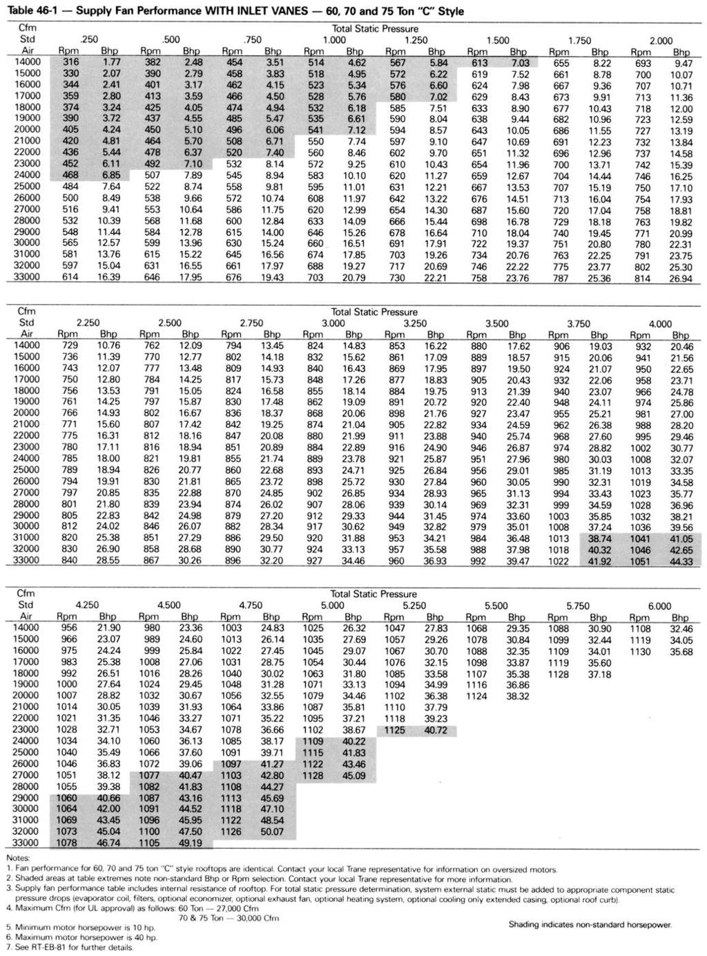
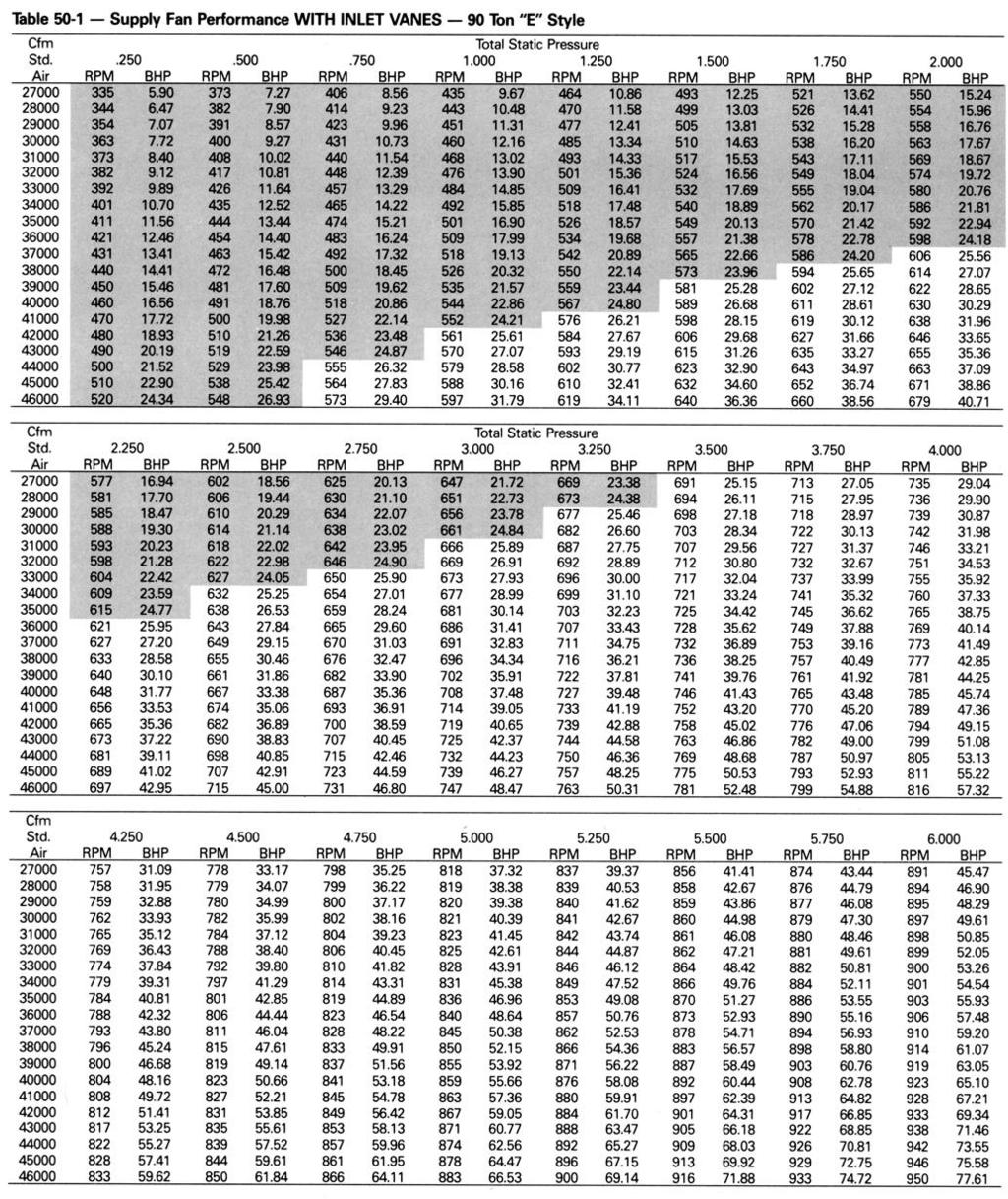
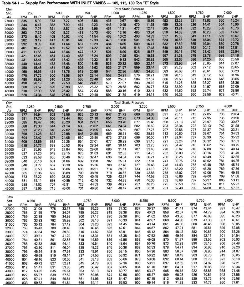
4 Features and Benefits Options Building For Optimum Comfort Control Statitrac Direct Space Pressurization Control Trane Statitrac control is a highly efficient method of maintaining accurate building pressure control with large rooftop air conditioning. High efficiency is achieved with a 100% modulating exhaust fan that operates only when needed compared to some systems that operate continually. And most of the operating hours of the 100% modulating exhaust fan are at part load, saving more energy. Trane Statitrac, with the 100% modulating exhaust system provides comfort and economy for buildings with large rooftop air conditioning systems. Statitrac control is simple. The modulating exhaust fan maintains the desired building pressure, saving energy while keeping occupants comfortable. Proper pressurization eliminates annoying door whistling and doors standing open. FC Fans With Inlet Guide Vanes Trane foward-curved fans with inlet guide vanes are a very efficient means of modulating airflow. Unloading efficiency is substantially better than other methods of modulation. The inlet vanes prerotate the air in the direction of the fan wheel, decreasing static pressure and horsepower, essentially unloading the fan wheel. The unloading characteristics of a Trane FC fan with inlet guide vanes result in superior part load performance. 4


5 Features and Benefits Trane 3-D Scroll Compressor Trane ton rooftops feature the 3-D Scroll compressor with 64% fewer parts than equal capacity reciprocating compressors. Fewer parts than an equal capacity reciprocating compressor means significant reliability and efficiency benefits. The single orbiting scroll eliminates the need for pistons, connecting rods, wrist pans and valves. Fewer parts lead to increased reliability. Fewer moving parts, less rotating mass and less internal friction means greater efficiency than reciprocating compressors. Trane 3-D Scroll compliance provides important reliability and efficiency benefits. 3-D compliance allows the orbiting scrolls to touch in all three dimensions, forming a completely enclosed compression chamber which leads to increased efficiency. In addition, 3-D compliance means the orbiting scrolls only touch with enough force to create a seal so there is no wear between the scroll plates, The most outstanding feature of the scroll compressor 3-D compliance is that the compressor gives to allow liquid or dirt to pass through without damaging the compressor. In a reciprocating compressor, however, the liquid or dirt has no place to go and can cause serious damage. The 3-D Scroll compressor has a very smooth compression cycle with torque variations that are only 30 percent of a reciprocating compressor. This means the scroll compressor imposes very little stress on the motor for greater reliability. And low torque variation results in less noise and vibration. With over ten years of development and testing, Trane 3-D Scroll compressors have undergone over 400,000 hours of laboratory testing and field operation. This work combined with 14 patents makes Trane the worldwide leader in air conditioning scroll compressor technology. One of two matched scroll plates the distinguishing feature of the scroll compressor. Chart illustrates low torque variation of 3-D Scroll compressor vs reciprocating compressor. 5
6 Number Description 6
7 Model Number Description
8 General 8
9 General

10 General 10
11 Application Considerations EXHAUST AIR OPTIONS When is it necessary to provide building exhaust? Whenever an outdoor air economizer is used, a building generally requires an exhaust system. The purpose of the exhaust system is to exhaust the proper amount of air to prevent over or under-pressurization of the building. The idea is to exhaust 10 to 20 percent less air than the amount of outside air going into the building. This maintains a slightly positive building pressure. A building may have all or part of its exhaust system in the rooftop unit. Often, a building provides exhaust external to the air conditioning equipment. This external exhaust must be considered when selecting the rooftop exhaust system. Trane rooftop units offer three types of exhaust systems: percent modulating exhaust percent power exhaust. 3 Barometric relief dampers. Application Recommendations Percent Exhaust System Competitive rooftops use a return air fan system for controlling the amount of exhaust air during economizer operation. The return fan is in series with the supply fan and must operate whenever the supply fan is operating. During economizer operation, the economizer outdoor air dampers control the position of the return and exhaust air dampers, to exhaust the proper amount of air. The disadvantage of a return air fan is that it runs continuously, versus an exhaust fan which runs only during economizer operation. Also, the return fan must discharge air in two directions, through the return air dampers and/or exhaust air dampers, resulting in less efficient operation compared to an exhaust fan. The 20 through 130-ton rooftop unit offers modulating 100 percent exhaust fans. This fan system has performance capabilities equal to the supply fan. It operates only when the economizer outdoor air dampers are open beyond an adjustable minimum position. The amount of air exhausted by this fan is controlled by modulating discharge dampers at the fan outlet. The discharge damper position is controlled by a signal that varies with the position of the economizer dampers on constant volume rooftops. So, when the modulating exhaust fan starts, its discharge dampers are fully closed, and airflow is only 15 to 20 percent. For VAV rooftops, the 100 percent modulating exhaust fan s discharge dampers are modulated in response to building pressure. A differential pressure control system, called Statitrac, uses a photoelectric differential pressure controller to compare indoor building pressure to outdoor ambient atmospheric pressure. The exhaust fan is turned on when the economizer s outdoor air dampers open beyond minimum position. The pressure controller then modulates the discharge dampers to control the building pressure to within the adjustable, specified range on the front of the pressure controller. See Figure Figure 1-1 Statitrac Controller 11
12 Application Considerations Advantages of the Statitrac 100 percent modulating exhaust fan system are: a The exhaust fan runs only when the economizer dampers are above a minimum position. b Statitrac compensates for pressure variations within the building from remote exhaust fans. c The exhaust fan discharges in a single direction resulting in more efficient fan operation. d Because discharge dampers modulate airflow, the exhaust fan will be running unloaded whenever the economizer dampers are less than 100 percent open. With an exhaust fan system, the supply fan must be sized to pull the return air back to the unit through the return system during non-economizer operation. However, a supply fan can. typically overcome return duct losses more efficiently than a return air fan system. Essentially, one large fan by itself is normally more efficient than two fans in series. The reason for either a return air fan or an exhaust fan is to control building pressure. The Trane 100 percent modulating exhaust fan does a better job controlling building pressure than return fans simply because 100 percent modulating exhaust fan discharge dampers are controlled directly from building pressure, rather than from an indirect indicator of building pressure such as damper position. The 100 percent modulating exhaust fan may be used on any rooftop application that has an outdoor air economizer, However, when most exhaust is handled external to the rooftop or when building pressure is not critical, one of the other less expensive methods of exhaust may be used Percent Exhaust Fan The 50 percent exhaust fan is a single, non-modulating exhaust fan with half the air-moving capabilities of the supply fan system. The experience of The Trane Company that a nonmodulating exhaust fan selected for 40 to 50 percent of nominal supply cfm can be applied successfully. The 50 percent exhaust fan generally should not be selected for more than 40 to 50 percent of design supply airflow. Since it is an on/off nonmodulating fan, it does not vary exhaust cfm with the amount of outside air entering the building. Therefore, if selected for more than 40 to 50 percent of supply airflow, the building may become underpressurized when economizer operation is allowing lesser amounts of outdoor air into the building. If, however, building pressure is not of a critical nature, the non-modulating exhaust fan may be sized for more than 50 percent of design supply airflow. 3 Barometric Relief Dampers Barometric relief dampers consist of gravity dampers which open with increased building pressure. As the building pressure increases, the pressure in the unit return section also increases, opening the dampers and relieving air. Barometric relief may be used to provide relief for single story buildings with no return ductwork and exhaust requirements less than 25 percent. Figure 12-1 Plan View of Modulating 100 Percent Exhaust Fan 12
13 Application Considerations One-Zone VAV A one-zone VAV system consists of a commercial rooftop with refrigeration controls similar to a standard shutoff VAV unit. The rooftop s inlet vanes are controlled from a space thermostat rather than a static pressure controller. The rooftop is used on an airside distribution system without variable air volume boxes. Because there are no VAV boxes in the ductwork, all air modulation is accomplished via the unit s inlet vanes. The following must be properly addressed if a successful one-zone VAV system is to be installed: While the one-zone VAV system offers the airside savings of a conventional rooftop/vav system, it does not offer the zoning flexibility. Specifically, the system does not have the capability to satisfy simultaneous heating and cooling requirements or simultaneous cooling requirements that are not the same percentage of the design load. As a general rule, a one-zone VAV system can be successfully used in a system where a constant volume rooftop would be properly applied. Horizontal Discharge The typical rooftop installation has both the supply and return air paths routed through the roof curb and building roof. However, many rooftop installations require horizontal supply and/or return from the rooftop because of a building s unique design or for acoustic considerations. Trane has two ways to accomplish horizontal supply and/or return. The first applies to all Trane C and E style rooftop units. Special field supplied curbs are installed that use the units standard discharge and return openings. The supply and return air is routed through the curb to horizontal openings on the sides of the curb. The second method available for horizontal supply and return applies to SXHC, SLHC, SSHC, SXHE and E style units with design special hot water or steam heat. With this method the standard discharge and return openings are blocked in the field. Access panels are removed as indicated in Figures 66-1 and 67-1, These openings are used for the discharge and return. This method can only be applied to extended casing cooling only, hot water or steam heat units. No special curb is needed. SXHC Units Figure 66-1 is a simplified sketch of the rooftop showing which panels can be used for horizontal supply and/or return. To supply air horizontally, the panels that normally house the heat accessory controls (Panel A) and the gas heat barometric dampers (Panel B) can be removed and either of the openings used as a unit discharge. To return air horizontally, the exhaust fan access door (Panel C) can be removed and used as a return opening. Tables 66-1, 2 and 3 show dimensions for those panels. SXHE Units Figure 67-1 is a simplified sketch showing which panels can be used for horizontal supply and/or return on SXHE units. On SXHE units only one side of the extended casing may be used for horizontal supply because of the location of the unit control panel. There are, however, two panels (Panels A) on the side opposite the control box which can be removed along with the vertical support which separates the two. Removal of the vertical support is optional, but will ensure maximum airflow. Horizontal return is accomplished in much the same way as on SXHCs by removing the exhaust fan access door (Panel B). See Tables 67-1 and 2 for SXHE panel dimensions. When using an SXHC/SXHE rooftop for horizontal supply and return, an additional pressure drop must be added to the supply external static to account for the 90 degree turn the air is making, This additional pressure drop depends on airflow and rooftop size, but a range of 0.10 inches to 0.30 inches can be expected. The openings on the rooftop all have a one inch lip around the perimeter to facilitate ductwork attachment. If exhaust fans are being used on an SXHC/SXHE unit with horizontal return, provisions should be made for access to the exhaust components, since the access door opening is now being used as a return. Perhaps the return ductwork attachment to the rooftop can include a section of removable duct. Use the dimensions provided and the supply and exhaust cfm to calculate the velocity (ft/min) through the openings. 13
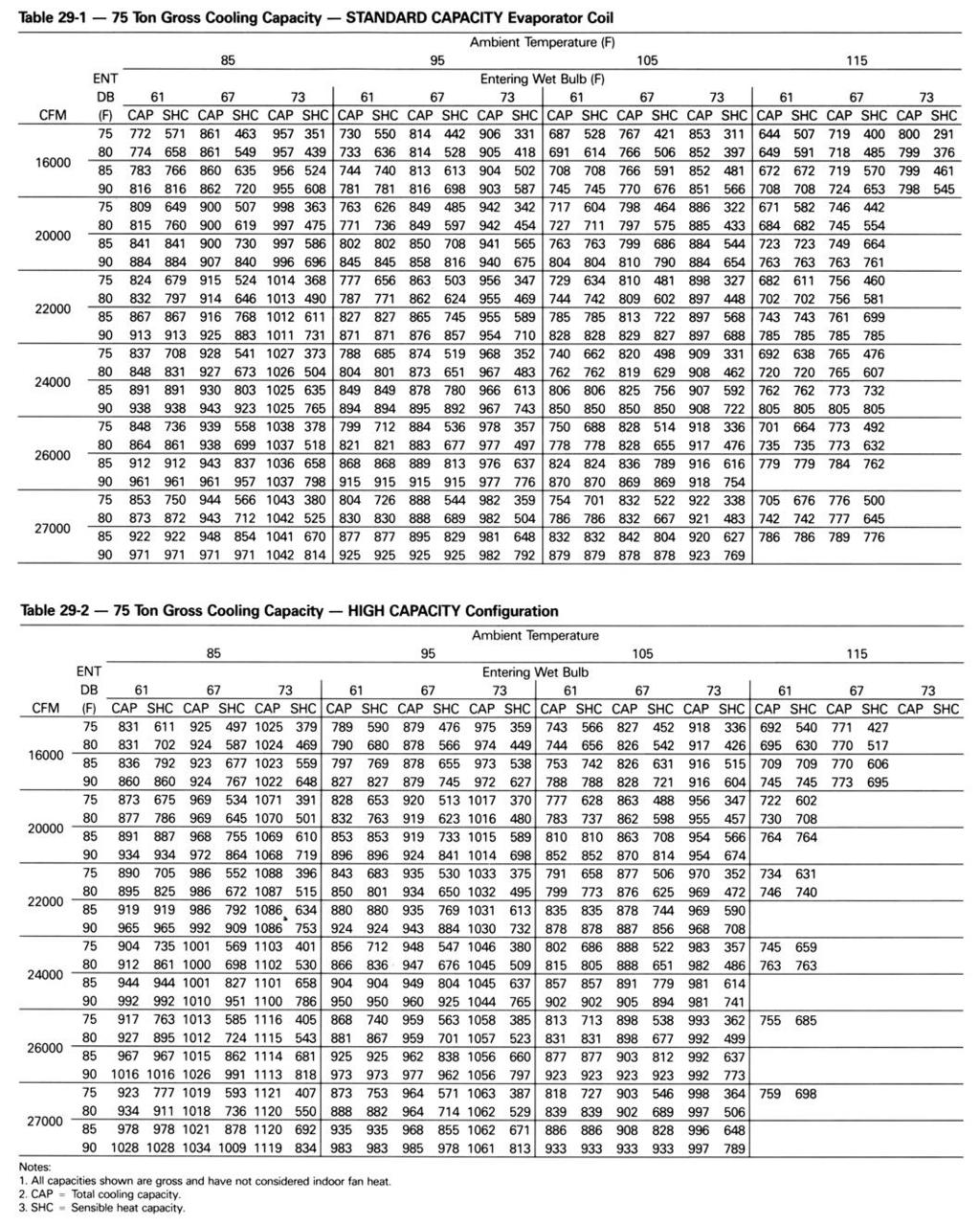
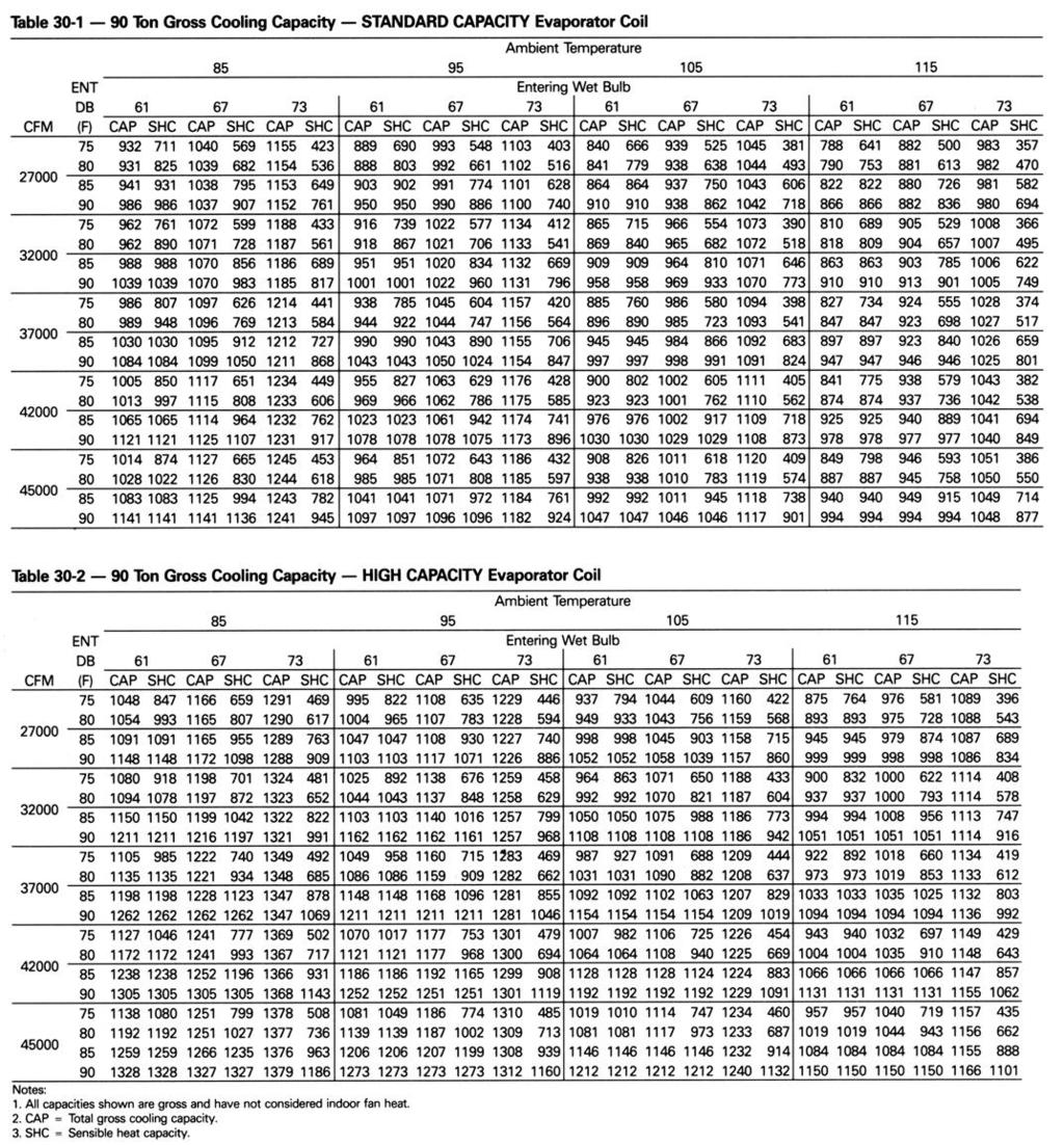
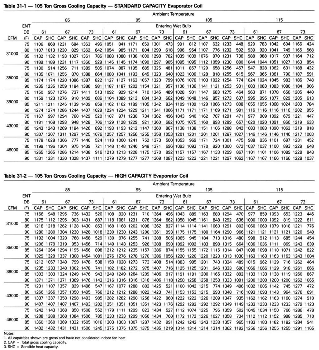
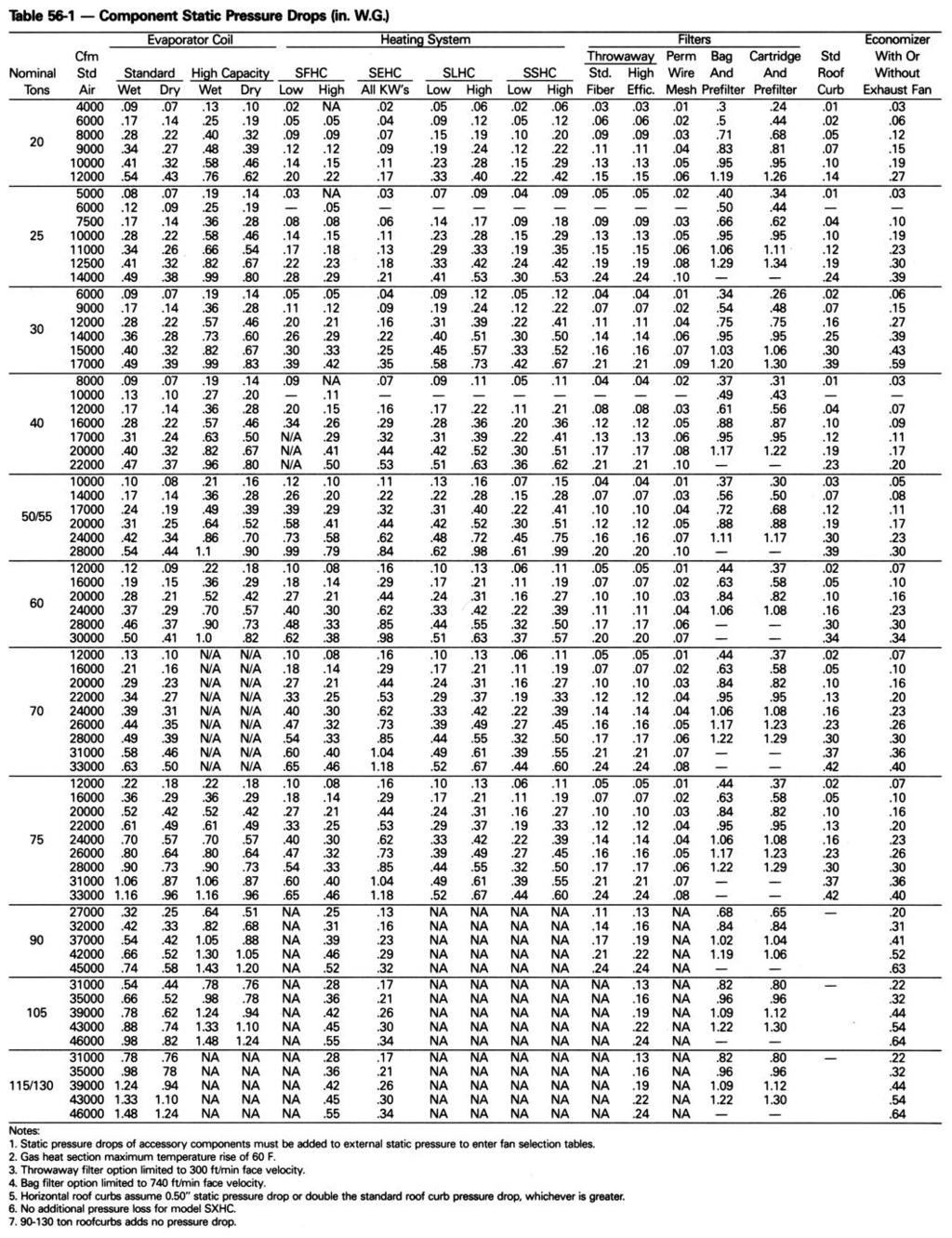
14 Application Considerations High Capacity Evaporator Coil Rooftops are popular because of their packaged nature. Everything needed is contained in one box; mix-matching is neither necessary nor available. With this convenience comes some disadvantages, one being that the rooftop s cooling capacity may not match the building load exactly. It is conceivable that a 50-ton rooftop would need to be used on an application that is 41 tons, simply because the 40-ton rooftop does not meet capacity. In order to avoid such occurrences, and to more closely match the rooftop s capacity to the building load, a high capacity evaporator coil option is available on Trane 20 through 105 ton rooftop equipment. These high capacity coils have an increased number of evaporator coil rows as compared to standard and enhanced evaporator tube surfaces, resulting in a higher capacity. Capacity tables for both standard and high capacity coils are available in the cooling data section of this catalog. See Table 56-1 for the pressure drops associated with the high capacity coil option. This pressure drop should be added to the total static pressure used to size the supply fan motor. Corrosive Atmospheres Trane large rooftops are designed and built to industrial standards and will perform to those standards for an extended period depending on the hours of use, the quality of maintenance performed, and the regularity of that maintenance, One factor that can have an adverse effect on unit life is its operation in a corrosive environment. When large rooftops are operated in corrosive environments, Trane recommends that copper fins be utilized on the condenser and/or evaporator coil. Because copper is more resistant to corrosion than aluminum, coil life expectancy is greatly increased. Some industry applications expose equipment to corrosive agents that even copper cannot fully resist, For those special applications, a baked phenolic resin coating (i.e. Heresite) is highly desirable. Baked phenolic coatings or copper fins on the condenser and/or evaporator coils are available on an optional basis. Ventilation Override Sequences One of the benefits of using an exhaust fan rather than a return fan, in addition to the benefits of lower energy usage and improved building pressurization control, is that the rooftop can be used as part of a ventilation override system. The rooftop controls can be modified to respond to a signal from a fieldsupplied smoke detector in a number of ways. One possible sequence with such a ventilation override system on a variable air volume rooftop with economizer and 100 percent modulating exhaust fan follows: Ž Open outside air dampers/close return air dampers. Turn supply fan off. Ž Turn exhaust fan on/exhaust dampers open. Ž Lock out cooling and heating. Ž Close inlet vanes. Override night setback and morning warm-up. With only the exhaust fans running (supply fan off), the space that is conditioned by that rooftop would become negatively pressurized. This is desirable for clearing the area of smoke from the now-extinguished fire, possibly keeping smoke out of areas that were not damaged. Other schemes are possible. Perhaps a positively pressurized space is desired instead of a negatively pressurized space. In this case, the supply fan should be turned on with inlet vanes open and the exhaust fan should be turned off. (Of course, the VAV boxes would need to be interlocked and opened to avoid severely overpressurized ductwork.) These types of schemes can be done rather easily when exhaust fans are part of the rooftop system, rather than return fans. Return fans do not offer the flexibility of exhaust fans in this case. What would initiate the ventilation override control sequence? Typically, a manual switch is used and located near the fire protection control panel. This enables the fire department access to the control for use during or after a fire. It is also possible to initiate the sequence from a field-installed automatic smoke detector. In either case, a contact closure begins the ventilation override control. 14
15 Application Considerations Acoustical Considerations The ideal time to make provisions to reduce sound transmission is during the project design phase. The most economical means of avoiding an acoustical problem is to place any rooftop equipment away from acoustically critical area. Proper placement of rooftop equipment is critical to reducing transmitted sound levels to the building. If possible, rooftop equipment should not be located directly above areas such as: offices, conference rooms, executive office areas and classrooms. Ideal locations area areas above corridors, utility rooms, toilet facilities, or other areas where higher sound levels are acceptable. Several basic guidelines for unit placement should be followed to minimize sound transmission through the building structure: 1 Never cantilever the compressor section of the unit. A structural cross member must support this end of the unit. 2 Locate the unit s center of gravity close to or over column or a main support beam. 3 If the roof structure is very light, roof joist may be replaced by a structural shape in the critical areas described above. 4 If several units are to be placed on one span, they should be staggered to reduce deflection over that span. It is impossible to totally quantify the effect of building structure on sound transmission, since this depends on the response of the roof and building members to the sound and vibration of the unit components. However, the guidelines listed above are experienceproven guidelines which will help reduce sound transmission. There are several other sources of unit sound, i.e., supply fan, compressors, exhaust fans, condenser fans and aerodynamic noise generated at the duct fittings. Refer to the ASHRAE Systems Guide, Chapter 32, 1984 edition for guidelines for minimizing the generation of aerodynamic noise associated with duct fittings. Engineering Bulletin RT-EB-80 describes various duct installation considerations specifically addressing indoor sound level concerns. This bulletin includes sound power data on Trane rooftops 20 tons through 130 tons. Ask the local Trane representative for this informative engineering bulletin. The VariTrane Computerized Duct Design Program can be used to analyze the truck duct, run-out duct, variable air volume control unit and terminal unit noise attenuation. This program quantifies the airborne sound generation that can be expected in each terminal so that the designer can identify potential sound problems and make design alterations before equipment installation. Clearance Requirements The recommended clearances identified with unit dimensions should be maintained to assure adequate serviceability, maximum capacity and peak operating efficiency. A reduction in unit clearance could result in condenser coil starvation or warm condenser air recirculation. If the clearances shown are not possible on a particular job, consider the following: Do the clearances available allow for major service work such as changing compressors or coils? Do the clearances available allow for proper outside air intake, exhaust air removal and condenser airflow? If screening around the unit is being used, is there a possibility of air recirculation from the exhaust to the outside air intake or from condenser exhaust to condenser intake? Actual clearances which appear inadequate should be reviewed with a local Trane sales engineer. When two or more units are to be placed side by side, the distance between the units should be increased to 150 percent of the recommended single unit clearance. The units should also be staggered as shown in Figure 16-1 for two reasons: 1 To reduce span deflection if more than one unit is placed on a single span. Reducing deflection discourages sound transmission. 2 To assure proper diffusion of exhaust air before contact with the outside air intake of adjacent unit. 15
16 Application Considerations Duct Design It is important to note that the rated capacities of the rooftop can be met only if the rooftop is properly installed in the field, A well designed duct system is essential in meeting these capacities. The satisfactory distribution of air throughout the system requires that there be an unrestricted and uniform airflow from the rooftop discharge duct. This discharge section should be straight for at least several duct diameters to allow the conversion of fan energy from velocity pressure to static pressure, However, when job conditions dictate elbows be installed near the rooftop outlet, the loss of capacity and static pressure may be reduced through the use of guide vanes and proper direction of the bend in the elbow. The high velocity side of the rooftop outlet should be directed at the outside radius of the elbow rather than the inside as illustrated in Figure
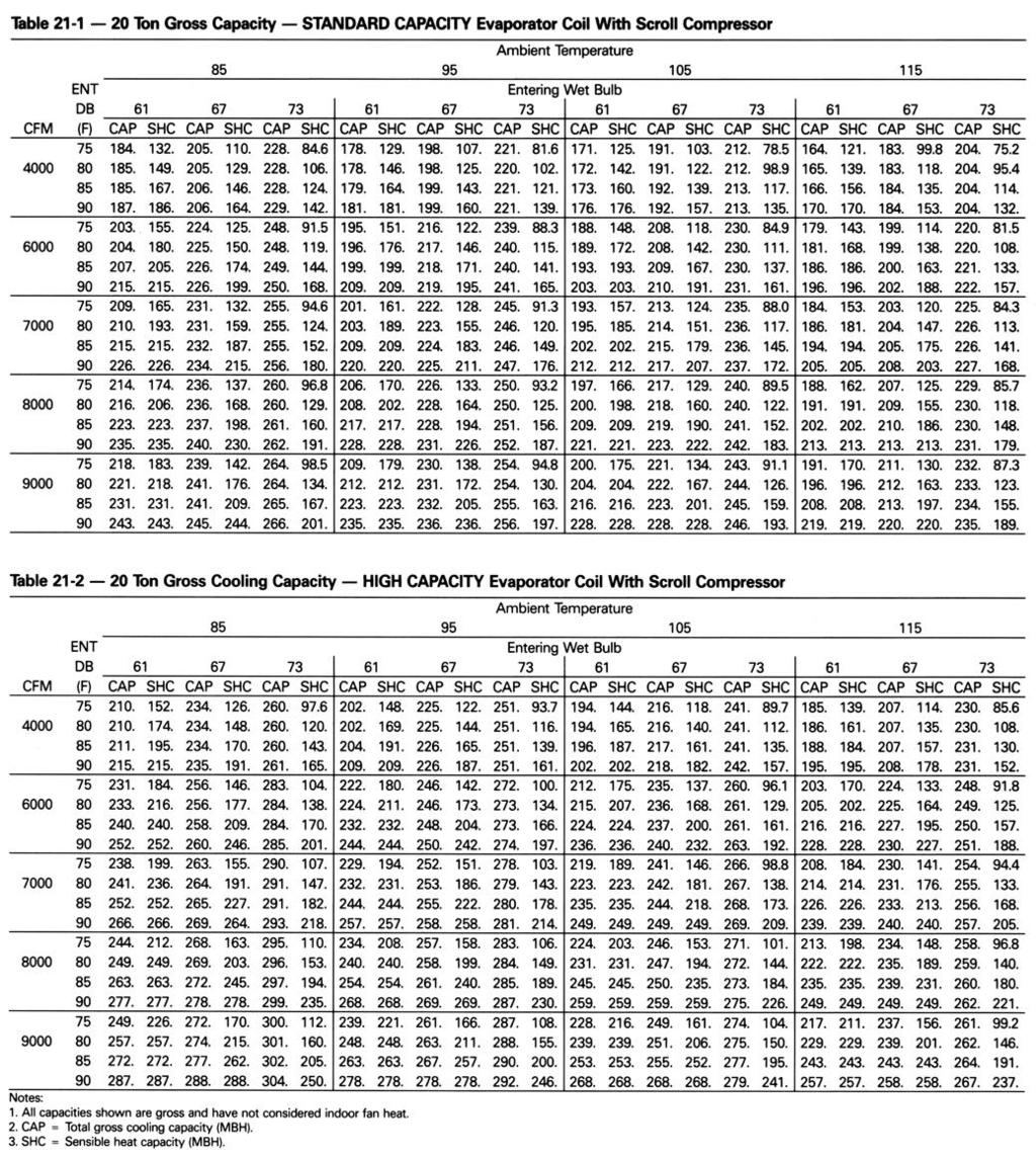
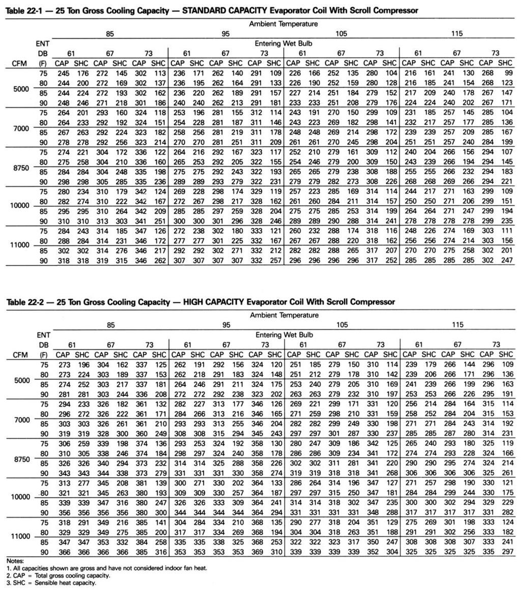
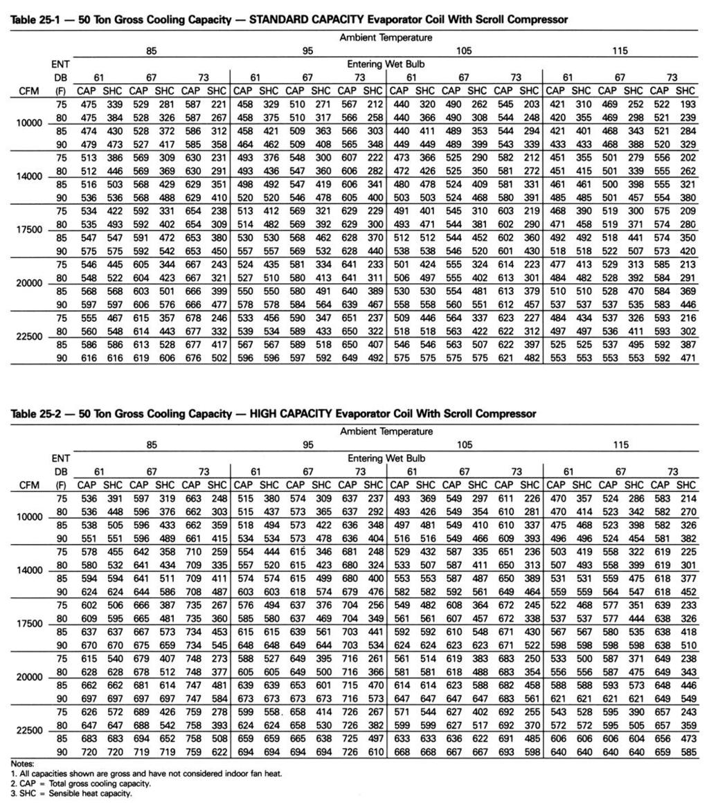
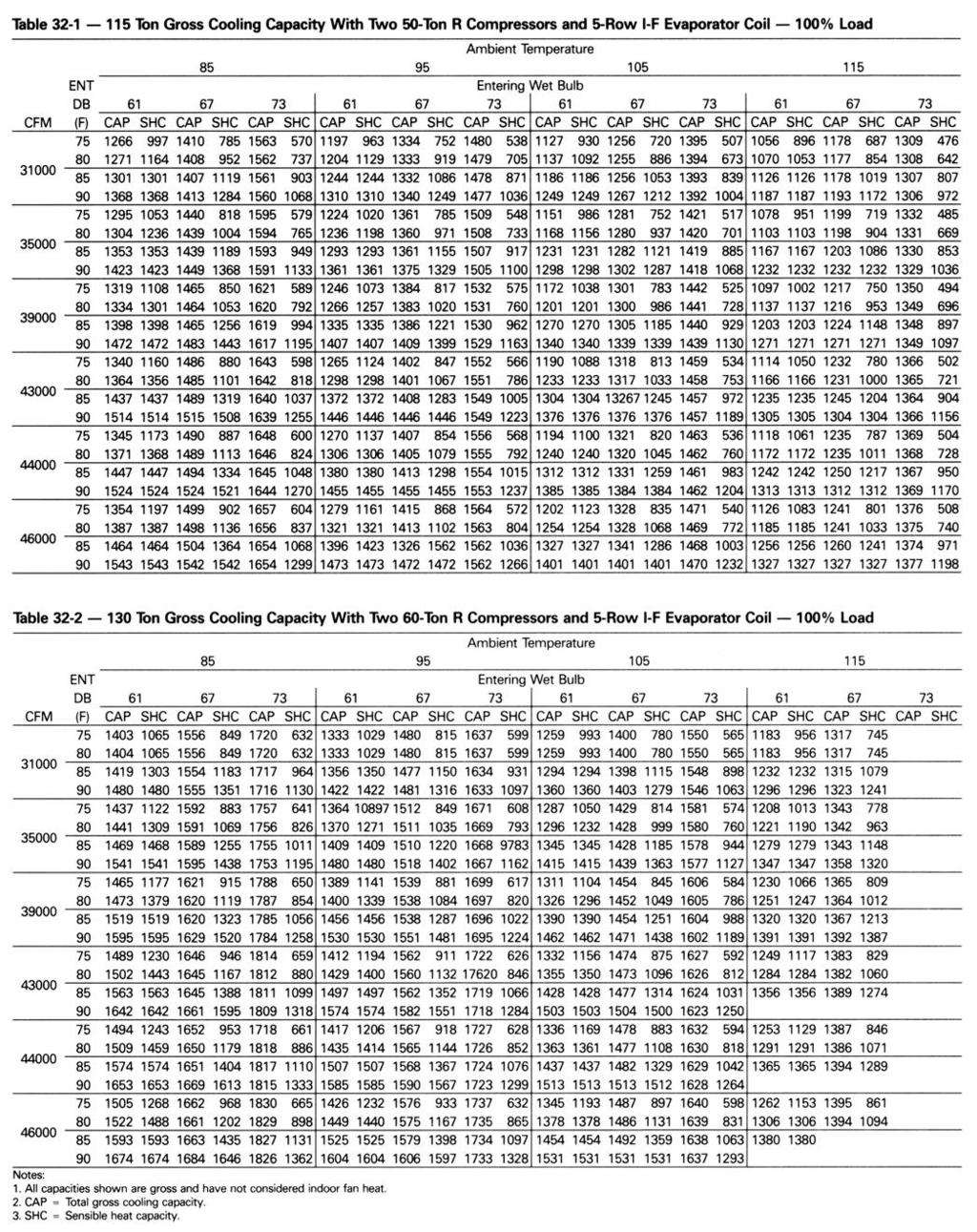
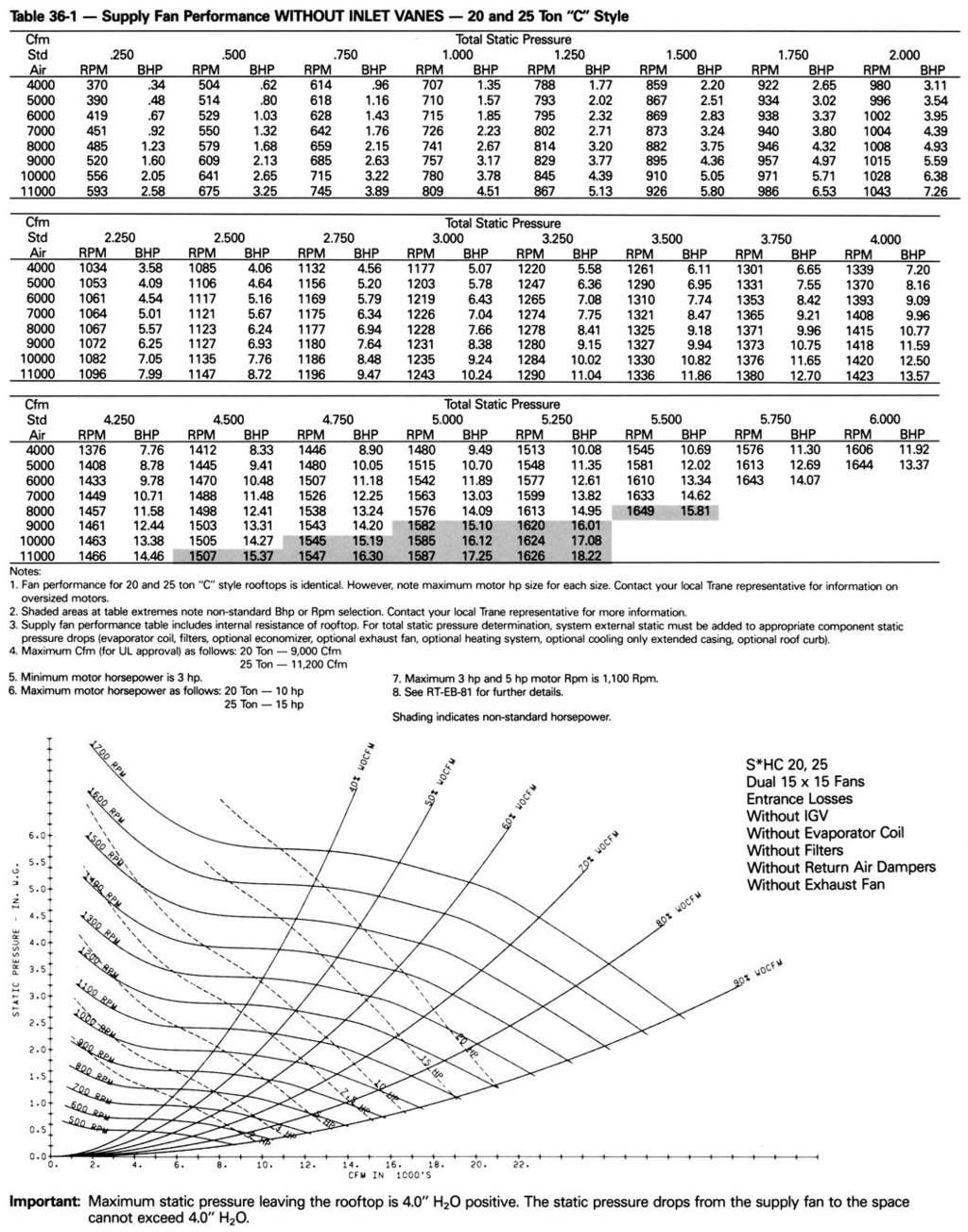
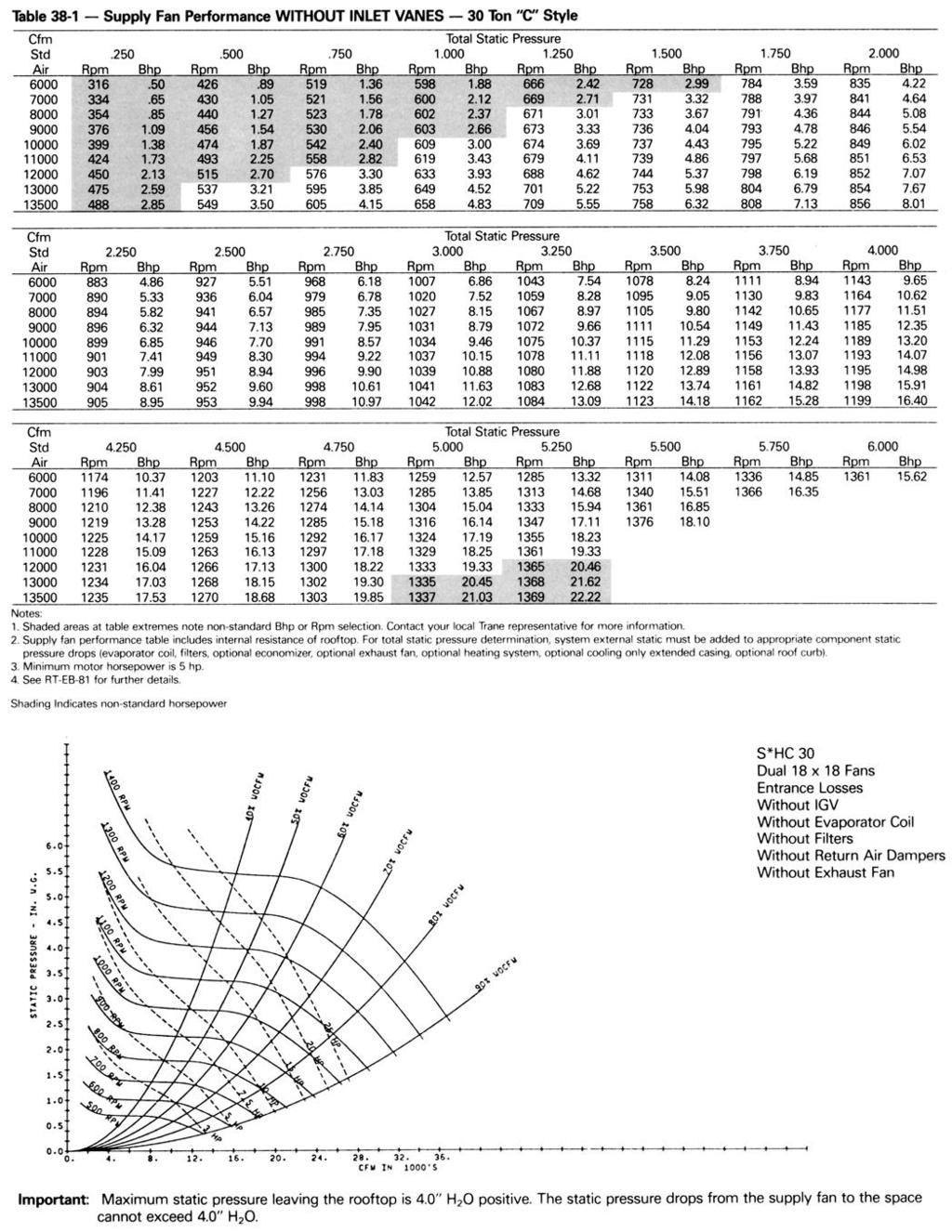
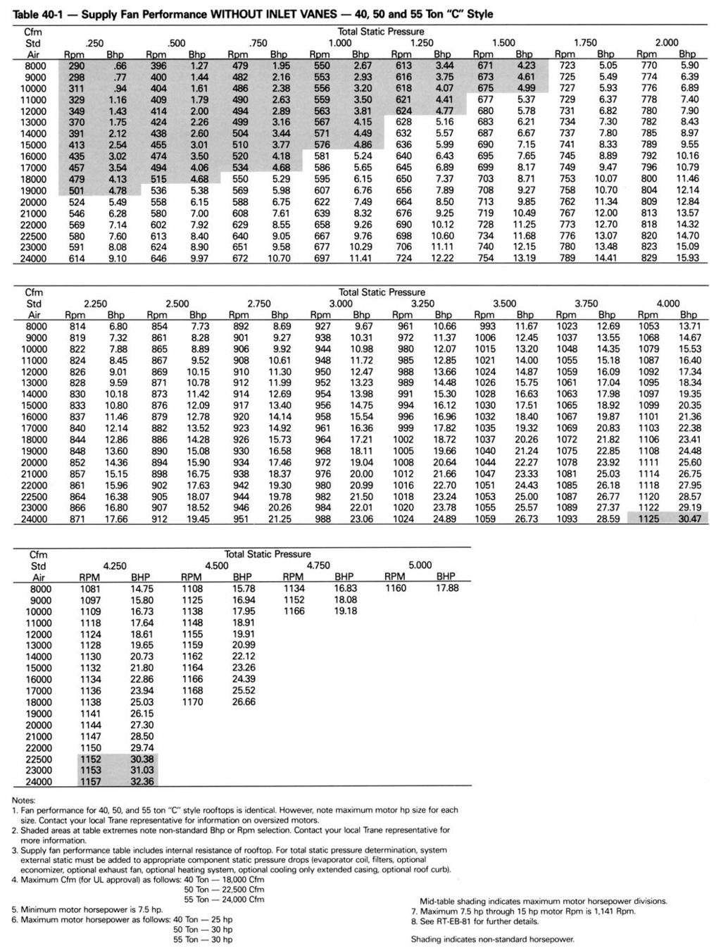
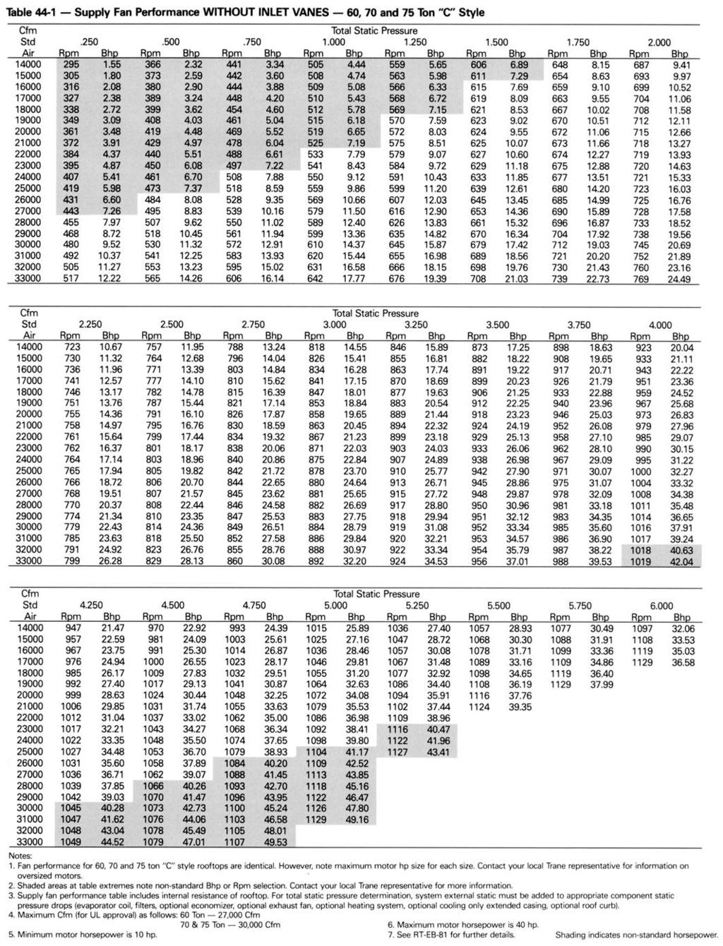
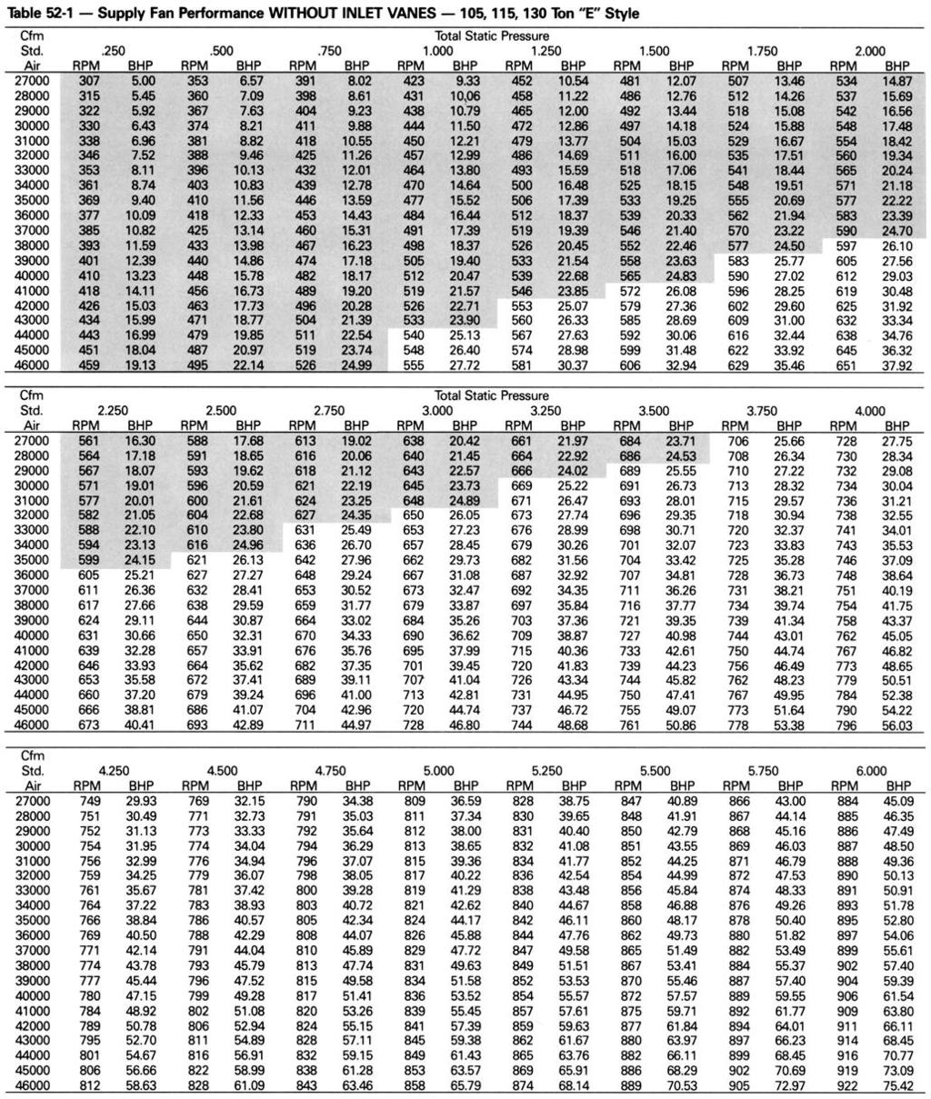
17 Selection Procedure This section outlines a step-by-step procedure that may be used to select a Trane single-zone air conditioner. The sample selection is based on the following conditions Summer outdoor design conditions 95 DB/76 WB ambient temperature Summer room design conditions 78 DB/65 WB Total cooling load 430 MBh (35.8 tons) Sensible cooling load 345 MBh (28.8 tons) Outdoor air ventilation load 66.9 MBh Return air temperature 80 DB/65 WB Winter Design: Ž Winter outdoor design conditions OF Return air temperature 70 F Total heating load 475 MBh Winter outdoor air ventilation load 133 MBh Air Delivery : Supply fan cfm 17,500 cfm External static pressure 1.2 in wg Minimum outdoor air ventilation 1,750 cfm Exhaust fan cfm 12,000 cfm Return air duct negative static pressure 0.65 in wg Electrical Characteristics: Voltage/cycle/phase 460/60/3 Unit Accessories: Gas fired heat exchanger high heat module Throwaway filters Economizer Modulating 100 percent exhaust/return fan COOLING CAPACITY SELECTION Step 1 Nominal Unit Size Selection A summation of the peak cooling load and the outside air ventilation load shows 450 MBh MBh = MBh required unit capacity. From Table 25-1, a 50-ton unit capacity with standard capacity evaporator coil at 80 DB/65 WB, 95 F outdoor air temperature and 17,500 total supply cfm is 551 MBh total and 422 MBh sensible. Thus, a nominal 50-ton unit with standard capacity evaporator coil is selected. Step 2 Evaporator Coil Entering Conditions Mixed air dry bulb temperature determination: Using the minimum percent of OA (1,750 cfm 17,500 cfm = 10 percent), determine the mixture dry bulb to the evaporator. RADB + % OA (OADB RADB) = 80 + (0.10) (95 80) = = 81.5F Approximate wet bulb mixture temperature RAWB + % OA (OAWB RAWB) = 65 + (O.10) (76 65) = = 66.1 F Step 3 Determine Supply Fan Motor Heat Gain Having selected a nominal 50-ton unit, the supply fan bhp can be calculated. The supply fan motor heat gain must be considered in final determination of unit capacity. Supply Air Fan Determine unit total static pressure at design supply cfm: External Static Pressure 1.2 inches Evaporator Coil (Table 56-1) 0.25 inches Return Duct Negative Static Pressure 0.65 inches Heat Exchanger (Table 56-1) 0.31 inches Throwaway Filter (Table 56-1) 0.10 inches Economizer w/exhaust Fan (Table 56-1) 0.12 inches Trane Roof Curb (Table 56-1 ) 0.13 inches Unit Total Static Pressure 2.76 inches Using total of 17,500 cfm and total static pressure of 2.76 inches, enter Table Table 40-1 shows 15.3 bhp with 924 rpm. From Chart 18-1 supply fan motor heat gain = 46.0 MBh. 17
 Step 5 Determine Unit Capacity From Table 25-1, unit capacity at 81.5 DB/66.1 WB entering the evaporator, 17,500 supply air cfm, 95 F outdoor ambient, is 561 MBh (45.")
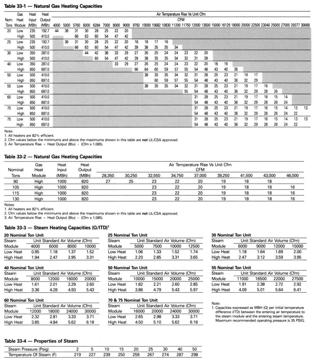
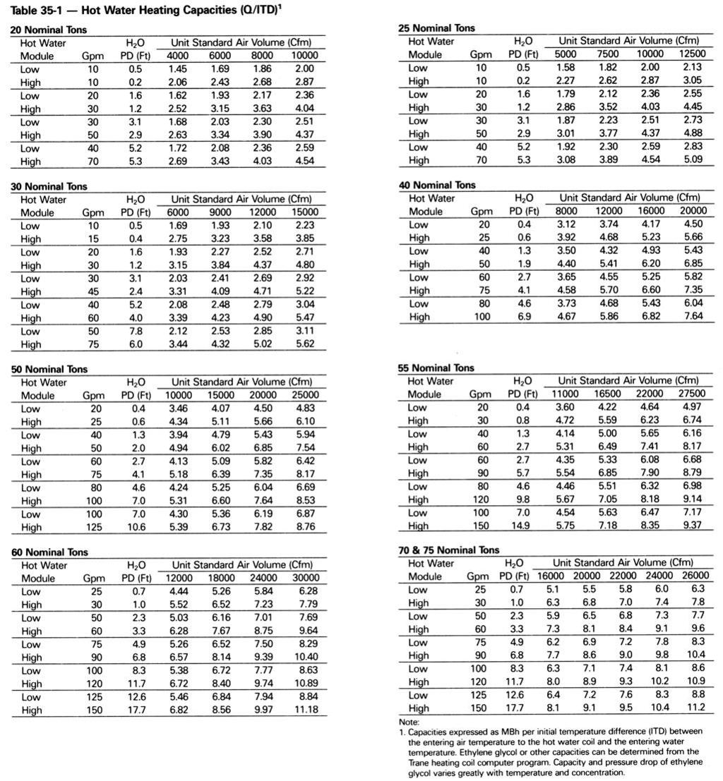
18 Selection Procedure Step 4 Determine Total Required Cooling Capacity Required capacity = Total peak load + OA load + supply air fan motor heat. Required capacity = = 543 MBh (45.2 tons) Step 5 Determine Unit Capacity From Table 25-1, unit capacity at 81.5 DB/66.1 WB entering the evaporator, 17,500 supply air cfm, 95 F outdoor ambient, is 561 MBh (45.8 tons) with 426 MBh sensible. Step 6 Determine Leaving Air Temperature Unit sensible heat capacity corrected for supply air fan motor heat = 426 MBh 46 MBh = 380 MBh. Supply air dry bulb temperature difference = Sensible Btu x Supply cfm = 380 MBh (1.085 x 17,500 cfm) = 20.0 F Supply air dry bulb = 81.5 DB 20.0 = 61.5 F Unit enthalpy difference = Total Btu 4.5 x Supply cfm = 561 MBh (4.5 x 17,500 cfm) = 7.12 Btu/lb Leaving enthalpy = h(ent WB) h(diff). From Table 20-1 h(ent WB) = 30.9 Btu/lb Leaving enthalpy = 30.9 Btu/lb 7.12 Btu/lb = Btu/lb Supply air wet bulb = 55.9 Leaving air temperature = 61.5 DB/55.9 WB HEATING CAPACITY SELECTION Step 1 Determine Air Temperature Entering Heating Module Mixed air temperature = RADB + % OA (OADB RADB) = 70 + (0.10) (0 70)=63F Supply air fan motor heat temperature rise = 46,000 Btu (1.085 x 17,500 cfm) = 2.42 F Air temperature entering heating module = = 65.4 F Step 2 Determine Total Winter Heating Load Total winter heating load = peak heating load + ventilation load supply fan motor heat = = 562 MBh Electric Heating System Unit operating on 460/60/3 power supply. From Table 34-3, kw maybe selected for a nominal 50-ton unit operating 460- volt power. The 170 kw heat module (580.1 MBh) will satisfy the winter heating load of 563 MBh. Table 34-1 shows an air temperature rise of 30.6 F for 17,500 cfm through the 170 kw heat module. Unit supply temperature at design heating conditions = mixed air temperature + air temperature rise = 65.4 F F = 96.0 F. 18 Gas Heating System (Natural Gas) From Table 33-1 select the high heat module (680 MBh output) to satisfy winter heating load of 563 MBh at unit cfm. Table 33-1 also shows an air temperature rise of 36.0 F for 17,500 cfm through the heating module. Unit supply temperature at design heating conditions = mixed air temperature + air temperature rise = 65.4 F F = F. Hot Water Heating Assume a hot water supply temperature of 190 F. Subtract the mixed air temperature from the hot water temperature to determine the ITD (initial temperature difference). ITD = 190 F 65.4 F = 125 F. Divide the winter heating load by ITD = 563 MBh 125 F = 4.50 Q/lTD. From Table 35-1, select the low heat module. By interpolation, a Q/lTD of 4.50 can be obtained at a gpm at Water pressure drop at 25.7 gpm is 0,57 ft. of water. Heat module temperature rise = Total Btu x Supply cfm = 563,000 (1.085 X 17,500) = 29.7 F Unit supply air temperature = mixed air temperature + air temperature rise = = 95 F.
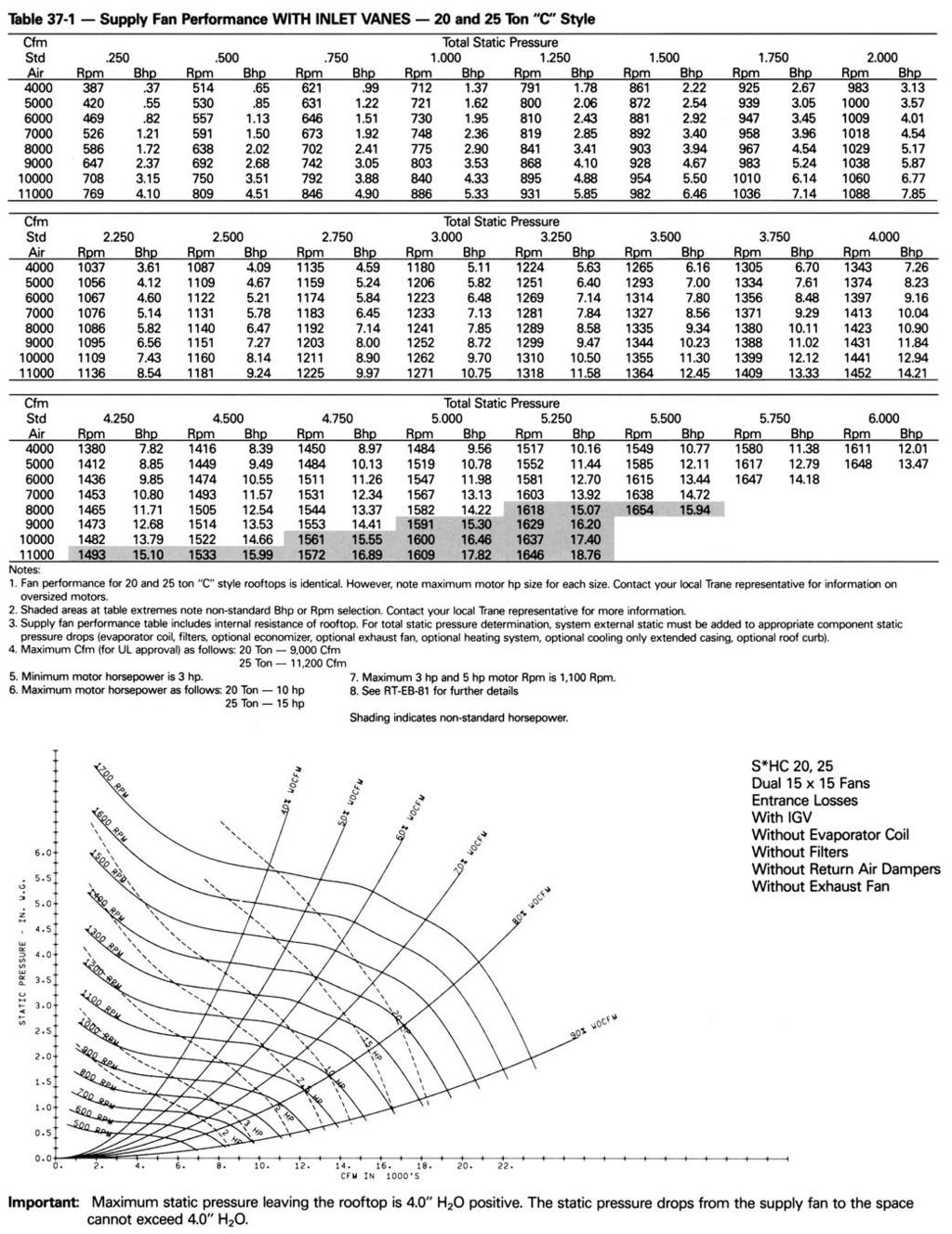
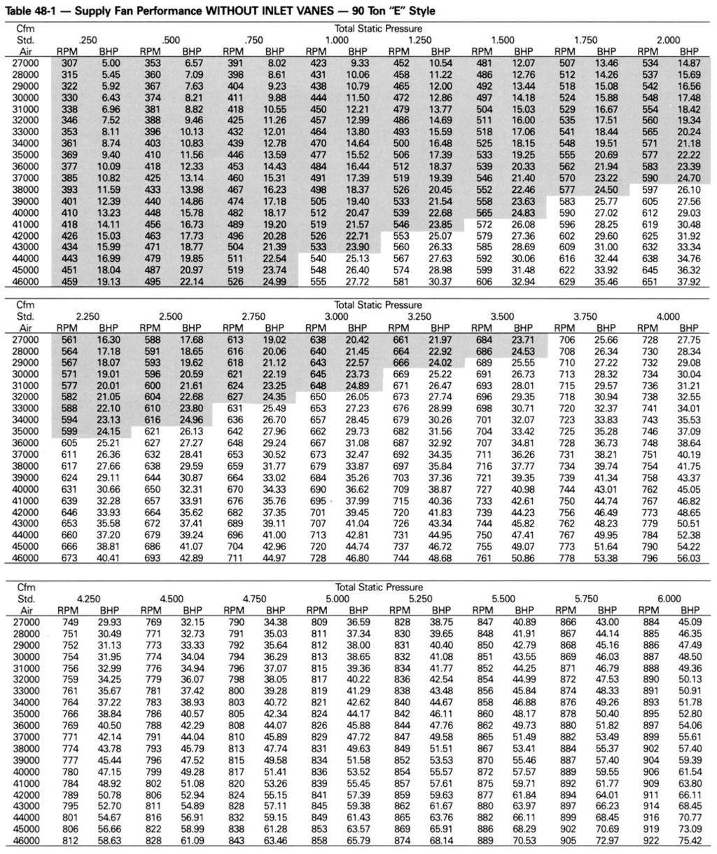
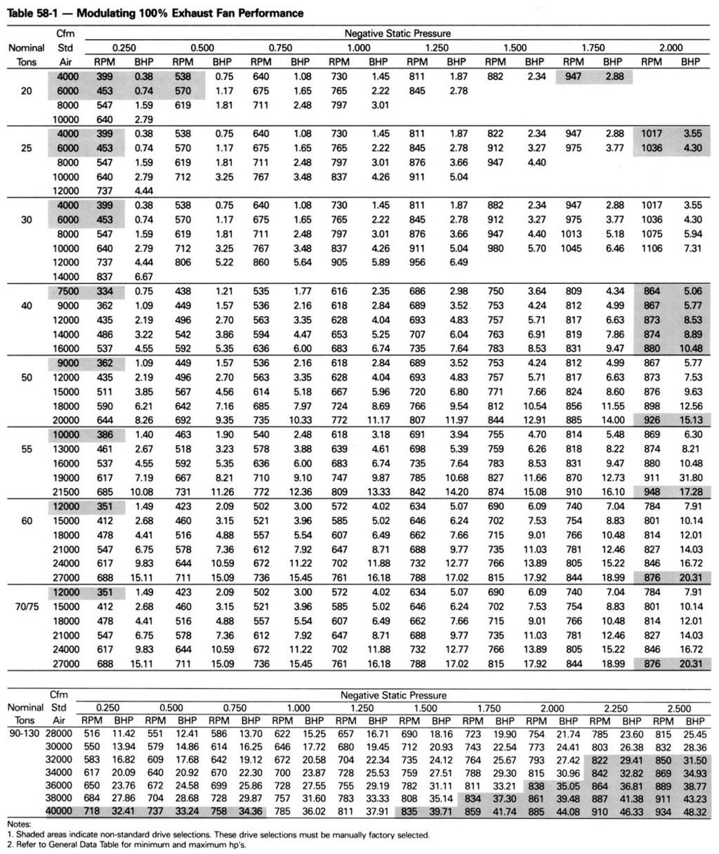
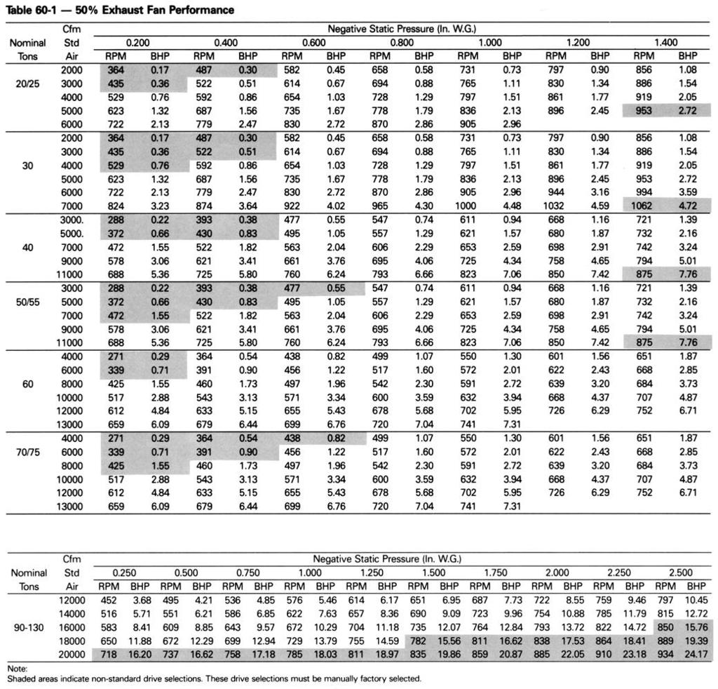
19 Selection Procedure Steam Heating System Assume a 15 psig steam supply. From Table 33-4, the saturated temperature steam is 250 F. Subtract mixed air temperature from the steam temperature to determine ITD. ITD = 250 F 65.4 F = 185 F. Divide winter heating load by ITD = 563 MBh 185 F = 3.04 Q/lTD. From Table 33-3, select the high heat module. The high heat module at 17,500 cfm has a Q/lTD = Heat module capacity, Q = ITD x Q/lTD = 185 F X 5.11 Q/lTD = 945 MBh Heat module air temperature rise Total Btu = x Supply cfm 945 Btu (1.085 x 17,500 cfm) = 49.8 F. Unit supply temperature at design conditions = mixed air temperature + air temperature rise = 65.4 F F = 115F. AIR DELlVERY PROCEDURE Supply fan performance tables include internal resistance of rooftop. For total static pressure determination, system external static must be added to appropriate component static pressure drop (evaporator coil, filters, optional economizer, optional exhaust fan, optional heating system, optional cooling only extended casing, optional roof curb). Supply Fan Motor Sizing The supply fan motor selected in the cooling capacity determination was 15.3 bhp and 924 rpm. Thus, a 20 hp supply fan motor is selected. Enter Table 57-1 to select the proper drive. For a 50-ton rooftop with 20 hp motor, a drive number rpm is selected. Exhaust Fan Motor Sizing The exhaust fan is selected based on total return system negative static pressure and exhaust fan cfm. Return system negative static include return duct static and roof curb static pressure drop. Return duct static pressure = 0.65 inches Trane roof curb (Table 56-1) = 0.12 inches Total return system negative static pressure = 0.77 inches Exhaust fan cfm = 12,000 cfm From Table 58-1, the required bhp is 3.45 hp at 574 rpm. Thus, the exhaust fan motor selected is 5 hp. To select a drive, enter Table 59-1 for a 5 hp motor for a 50 ton unit. Drive selection number rpm. Where altitudes are significantly above sea level, use Tables 20-2 and 20-3 and Figure 20-1 for applicable correction factors. UNIT ELECTRICAL REQUIREMENTS Selection procedures for electrical requirements for wire sizing amps, maximum fuse sizing, and dual element fuses are given in the electrical service section of this catalog. Altitude Corrections The rooftop performance tables and curves of this catalog are based on standard air (.075 Ibs/ft). If the rooftop airflow requirements are at other than standard conditions (sea level), an air density correction is needed to project accurate unit performance. Figure 20-1 shows the air density ratio at various temperatures and elevations. Trane rooftops are designed to operate between 40 and 90 degrees Fahrenheit leaving air temperature. The procedure to use when selecting a supply or exhaust fan on a rooftop for elevations and temperatures other than standard is as follows: 1 First, determine the air density ratio using Figure Divide the static pressure at the nonstandard condition by the air density ratio to obtain the corrected static pressure. 3 Use the actual cfm and the corrected static pressure to determine the fan rpm and bhp from the rooftop performance tables or curves. 4 The fan rpm is correct as selected. 5 Bhp must be multiplied by the air density ratio to obtain the actual operating bhp. In order to better illustrate this procedure, the following example is used: Consider a 60-ton rooftop unit that is to deliver 18,000 actual cfm at 3-inches total static pressure (tsp), 55 F leaving air temperature, at an elevation of 5,000 ft. 1 From Figure 20-1, the air density ratio is Tsp = 3.0-inches / 0.86 = inches tsp. 3 From the performance tables: a 60-ton rooftop (without inlet vanes) will deliver 18,000 cfm at 3.49-inches tsp at 906 rpm and bhp. 4 The rpm is correct as selected -906 rpm. 5 Bhp = X 0.86 = 18.3 bhp actual. Compressor MBh, SHR, and kw should be calculated at standard and then converted to actual using the correction factors in Table Apply these factors to the capacities selected at standard cfm so as to correct for the reduced mass flow rate across the condenser. Heat selections other than gas heat will not be affected by altitude. Nominal gas capacity (output) should be multiplied by the factors given in Table 20-3 before calculating the heating supply air temperature. 19
20 Adjustment Factors 20
21 21
22 22
23 23
24 24
25 25
26 26
27 27
28 28
29 29
30 30
31 31
32 32
33 33
34
35
36 36
37 37
38 38
39 39
40 40

41 41
42 42
43
44
45 45
46
47 47
48 48
49 49
50 50
51
52 52
53
54 54
55 55
56 56
57 57
58 58
59 59
60 60
61 61
62 Electrical Electrical Service Sizing Note: To correctly size electrical service wiring for... SAHC, SXHC/E, SFHC/E, SSHC, and SLHC units solve Equations 1 thru /230V SEHC units (dual-sourcepower) solve Equations 1 thru 4 and 9 thru 11. All other SEHC and SEHE units (single-source-power) solve Equations 1 thru 8. Equation No. 1: Minimum Circuit Ampacity (MCA) MCA = [1.25 x The largest of these: (Largest Compressor RLA OR Largest Motor FLA)] + Remaining Compressor RLA + Remaining Supply Fan FLA + Remaining Exhaust Fan FLA + Total Condenser Fan FLA Note: Round off the calculated MCA value to the nearest whole ampere. (If the MCA value ends in.5, round it upward.) Equation No. 2: Maximum Fuse Size (MFS) Case A: Compressor is the largest load MFS = (2.25 x Largest Compressor RLA) + Total Remaining Compressor RLA + Total Supply Fan FLA + Total Exhaust Fan FLA + Total Condenser Fan FLA Case B: Compressor is NOT the largest load MFS = (4.0 x Largest Motor RLA) + Total Compressor RLA + Total Remaining Supply Fan FLA + Total Remaining Exhaust Fan FLA + Total Condenser Fan FLA Note: Select the standard fuse rating equal to MFS; or select the next lower standard fuse rating. (Standard fuse sizes are taken from NEC ) Equation No. 3: Recommended Dual-Element Fuse Size (RDE) RDE = [1.5 x The larger of these: (Largest Compressor RLA or Largest Motor FLA)] + Remaining Compressor RLA + Total Remaining Supply Fan FLA + Total Remaining Exhaust Fan FLA + Total Condenser Fan FLA Note: Select the standard fuse rating equal to RDE; or select the next larger standard fuse rating. However, the RDE rating selected must not exceed the selected MFS rating. (Standard fuse sizes are taken from NEC ) Equation No. 4 Disconnect Switch Size (DSS) DSS = 1.15 x (Total Compressor RLA + Total Supply Fan FLA + Total Exhaust Fan FLA + Total Condenser Fan FLA) Note: Select a disconnect switch size that is equal to or larger than the DSS value calculated. All Single-Source-Power SEHC/E Units After solving Equations 1 thru 4, solve Equations 5 thru 8. Then compare the: MCA values calculated in Equations 1 and 5; MFS values calculated in Equations 2 and 6; RDE values calculated in Equations 3 and 7; and, DSS values calculated in Equations 4 and 8. In each instance, use the largest value of each pair to size the unit s electrical service. Equation No. 5 Minimum Circuit Ampacity (MCA) MCA = 1.25 X (Electric Heat Coil FLA + Total Supply Fan FLA + Total Exhaust Fan FLA) Equation No. 6: Maximum Fuse Size (MFS) MFS = 1.25 X (Electric Heat Coil FLA + Total Supply Fan FLA + Total Exhaust Fan FLA) Note: Select the standard fuse rating equal to MFS; or select the next larger standard fuse rating. Equation No. 7: Recommended Dual-Element Fuse Size (RDE) RDE = Electric Heat Coil FLA + (1.5 x Largest Single Fan FLA) + Total Remaining Supply Fan FLA + Total Remaining Exhaust Fan FLA Note: Select the standard fuse rating equal to RDE; or select the next larger standard fuse rating. However, the RDE size selected must not exceed the selected M FS size! Equation No. 8: Disconnect Switch Size (DSS) DSS = 1.15 x (Electric Heat Coil FLA + Total Supply Fan FLA + Total Exhaust Fan FLA) Note: Select a disconnect switch size that is equal to or larger than the DSS value calculated. Dual-Source-Power SEHC Units (200/230V Only): Solve Equations 1 thru 4 for refrigeration-side MCA, MFS, RDE and DSS values. Then, use Equations 9, 10 and 11 to determine electric heat section MCA, MFS and DSS values. Equation No. 9: Minimum Circuit Ampacity (MCA) MCA = 1.25 X Electric Heat Coil FLA Equation No. 10: Maximum Fuse Size (MFS) MFS = 1.25 X Electric Heat Coil FLA Note: Select a standard fuse rating equal to MFS; or select the next larger standard fuse rating. Equation No. 11: Disconnect Switch Size (DSS) DSS = 1.15 x Electric Heat Coil FLA Note: Select a disconnect switch size that is equal to or larger than the DSS value calculated. 62
63 Electrical 63

64 Controls Sequence Of Operation Shutoff VAV Rooftops Temperature Controls Units are provided with a supply air temperature sensor and Honeywell W7100 discharge air temperature controller. The supply air temperature sensor sends a continuous feedback signal to the W 7100 controller. This signal modulates the economizer and sequences the stages of mechanical cooling in response to the supply air temperature deviation from set point. An optional zone air temperature sensor is available which provides continuous input to the W7100 controller. The controller will reset the supply air temperature upwards based on a predetermined amount of reset which is adjustable from a remote potentiometer, The W7100 controller provides antishort cycle protection by utilizing a minimum four minute time-delay between successive on and off stages. Cooling On units with economizer, a call for cooling will modulate the fresh air dampers open. The rate of economizer modulation is based on deviation of the discharge temperature from set point, i.e., the further away from set point, the faster the fresh air damper will open. First stage of cooling will be allowed to start after the economizer reaches full open. At outdoor air temperatures above the enthalpy control setting, mechanical cooling only is used and the fresh air dampers remain at minimum position. On units without economizer, mechanical cooling only is used to satisfy the cooling requirements. The inlet vanes will close when the supply fan is shut down, except during night setback. Night Setback/Morning Warmup Standard heating options are available on shutoff/vav units for use with night setback and/or morning warmup operation only. Night setback and morning warmup are operated through the time clock provided in the remote panel with night setback. When the time clock switches to night setback or morning warmup operation, the outdoor air dampers close and cooling is locked out. As the building cools due to decreased load, the night setback thermostat energizes the rooftop heating function (single stage of heat provided on all units) and the evaporator fan. The rooftop unit will cycle through the evening as heating is required in the space. When the time clock switches from night setback to daytime operation, all heating functions are locked out and normal cooling operation begins. Morning warmup is two-stage. When night setback terminates, the rooftop will heat to stage 2 set point. The rooftop can reheat as many times as necessary to maintain stage 2 set point until stage 1 set point (typically 1 F higher than stage 2) is reached. At this point, the unit is released to daytime mode and cannot heat until the next night setback cycle. When using the night setback/morning warmup options in a heating/cooling rooftop, airflow must be maintained through the rooftop unit. This can be accomplished by electrically tying the VAV boxes to the rooftop time clock or by using changeover thermostats. Either of these methods will assure adequate airflow through the unit and satisfactory heating of the building. Inlet Vane Controls VAV units ordered with supply fan inlet vane controls (i.e., model no. digit 2.1 includes N ) are equipped with 2 static pressure regulators that control the action of inlet vane actuator(s). Inlet vane assemblies installed on the supply fan inlets regulate fan capacity and limit horsepower at lower system air requirements. When in any position other than full open, the vanes prespin intake air in the same direction as supply fan rotation. As the vanes approach the full-closed position, the amount of spin induced by the vanes increases at the same time that intake airflow and fan horsepower diminish. The field-adjustable static pressure regulators (1S22 and 1S23) are factoryinstalled in the unit control panel to govern the supply fan inlet vane actuators. These controls monitor duct static pressure (rather than atmospheric pressure) via a factory-installed pressure-sensing tube in the supply fanboard, and then modulate the inlet vane actuators accordingly to maintain the optimal rooftop discharge static. FROSTAT Suction Line Temperature Sensing The FROSTAT system eliminates hot gas bypass and adds a suction line surface temperature switch near the TXV bulb location to shut the cooling off when coil frosting conditions occur. The supply fans are not shut off and will de-ice the coil. Timers prevent the compressor from rapid cycling. The following flow chart describes the operation of FROSTAT suction line temperature sensing in large VAV rooftop units Economizer Cycle Note that the economizer is only allowed to function freely if ambient conditions are below the factory-set control range of enthalpy switch 3S20. If outside air is not suitable for economizing, the fresh air dampers drive to the minimum open position. (A potentiometer located on top of the economizer actuator cover establishes the minimum damper position.) 64
65 Controls Sequence Of Operation Temperature Controls A 20-volt dc regulated power supply is provided to the thermostat. A continuous signal of 1 to 16 volts dc is returned to the Honeywell Master Energy Controller (W973) by the thermostat. This signal is monitored by the controller to determine actual zone heating and cooling requirements. The controller will then, according to the voltage value received, operate the necessary mechanical components through relay stages which are sensitive to the zone signal. The control system provides two to four stages of mechanical refrigeration, depending upon tonnage and either of the following: Ž Three stages of electric heat. Two stages of gas heat. Cooling On those units with an economizer cycle, outdoor air is used to provide natural cooling at outdoor enthalpy below the setting on the enthalpy control (approximately 70 F at 55 percent relative humidity). Mechanical cooling is available to aid the economizer cycle at any ambient condition. During economizer operation, the controller modulates the outdoor and return air dampers between the minimum and full open settings to satisfy cooling requirements. If cooling demands cannot be met by the full open outdoor air dampers, mechanical cooling is activated (first and second stages if necessary). The outdoor air dampers remain open to take advantage of free natural cooling. However, due to the temperature sensing ability of the unit discharge sensor, the outdoor air dampers will begin to close at a discharge air temperature (off the evaporator coil) of 62 F. The outdoor air dampers will go to the minimum position at a discharge temperature of 50 F. This feature is termed positive modulating low limit. At outdoor air temperatures above the enthalpy control setting, mechanical cooling only is used and the outdoor air dampers remain at minimum position. If the unit does not include an economizer cycle, mechanical cooling only is used to satisfy cooling requirements. Outdoor air dampers may be set manually for a maximum of 25 percent outdoor air, if rooftop is equipped with 0 to 25 percent manual fresh air damper. Heating Gas-Fired Heating Upon a call for heating, the master energy controller closes the first stage heating contacts beginning the firing sequence. First, the heat exchanger combustion blower begins operation. Upon positive proving of combustion airflow, a prepurge cycle is executed. Then the ignition sequence takes place. If ignition is not proven, the ignition transformer is de-energized. After a time delay another prepurge cycle takes place followed by another attempt to ignite. If ignition fails a second time, the cycle repeats on 235 and 350 MBh modules. 500, 850 and 1000 MBh modules, the heating section, will be shut down and locked out until manually reset at the unit. As additional heat is required, the master energy controller will close the second stage heating contacts and either the second stage of the gas valve or a second stage gas valve will open depending on heat module size. During heating operation, an electronic flame safety control provides continuous flame supervision. If combustion should become unstable for any reason, heating will automatically shut down. After one minute, another 60 second prepurge and ignition cycle begins. As the heating requirement is satisfied, the master energy controller will open the second stage heating relay deenergizing the second stage of heat. When the requirement is fully satisfied, the first stage contacts are opened deenergizing the first stage of heat. The specific sequence of operation of the gas heat will depend on the size of the heat exchanger. Electric Heating The three stages of electric heat will be sequenced on the zone demand signal from the room thermostat. The zone signal is relayed to the master energy controller and the stages are sequenced based on load demand. Steam or Hot Water Heating Upon a call for heat, the master energy controller will close the heating contact feeding a varying voltage signal to the valve actuator. The valve will modulate to meet building demand as indicated by the voltage signal. When heating is satisfied, the heating relay will be deenergized, stopping the signal to the valve actuator. The valve will modulate closed.
66 Dimensional Horizontal Discharge On SXHC, SSHC & SLHC Rooftops The SXHC (extended casing cooling only), SSHC (steam heat) and SLHC (hot water heat) rooftop have the capability to supply and return air horizontally without the use of a horizontal supply/return curb. To supply air horizontally, the panels that normally house the heat accessory controls (Panel A) and the gas heat barometric dampers (Panel B) can be removed and either of the openings used as a unit discharge. To return air horizontally, the exhaust fan access door (Panel C) can be removed and used as a return opening. 66
67 Dimensional Horizontal Discharge On SXHE Rooftops The SXHE extended casing cooling only rooftop air conditioner has the capability to supply and return air horizontally without the use of a horizontal supply/return curb. To supply air horizontally, use Panel A only. The panel on the opposite side cannot be used on the E-style rooftop air conditioner due to the location of the unit control panel. (See note.) To return air horizontally, the exhaust fan access door (Panel B) can be removed and used as a return opening. 90 thru 130 ton SXHE rooftop air conditioners do not have a panel configuration like the C-style 20 to 75- ton rooftops. To achieve maximum airflow, vertical support can be removed after the unit has been placed on the roof curb. It is secured by four screws. 67

68

69
70 Dimensional 70
71 Dimensional

72 Weights 72
73 Options 73

74
75 Options A full range of factory-installed options are available on standard ship cycles allowing rooftop design best suited to each individual application. Cooling Only/Heating Casings Cooling Only Two casing choices are available, one designed for high airside efficiency and one for sound sensitive applications in extended casing only. Electric Heat Nickel-chromium electric heating elements in individually fused circuits of 48 amps or less and with all necessary safeties, A full range of sizing options is available. Natural Gas Heat Two-pass stainless steel tubular free floating heat exchanger has industrial type burner and combustion blower. Available with high or low fire and UL or CSA approval. Steam Heat ARI certified type NS coil with non-freeze steam distribution. Coils are pitched for drainage and are provided with steam modulating valve with actuator. High and low heat options are available. Hot Water Heat ARI certified type W coil mounted for drainage and provided with hot water modulating valve with actuator. High and low heat options are available. Power Supplies Rooftops are available with 200,230, 460 and 575 voltage power supplies. Exhaust No Exhaust Rooftops can be built for make-up air applications with no exhaust. Relief opening is sealed watertight. Barometric Relief Gravity dampers are provided that open to relieve positive pressure. 50 Percent Exhaust Fan One double inlet forward-curved fan can exhaust up to 50 percent of supply air. Control is on/off based on economizer damper position. Barometric dampers at fan outlet prevent air backdraft. 100 percent Modulating Exhaust Fan Two double inlet forward-curved fans can exhaust up to 100 percent supply air. Fans operate when economizer damper is open greater than minimum position. Discharge dampers at fan outlet modulate in response to economizer damper position on constant volume rooftops and in response to building pressure on variable air volume units. Filters Throwaway Two-inch, 30 percent efficient throwaway filters include rack (Standard). Ž Cleanable Wire Mesh Two-inch permanent washable wire mesh filters are provided with metal frame. High-Efficiency Throwaway Twoinch throwaway filters include rack and have an average arrestance in excess of 90 percent when tested in accordance with ASHRAE % Bag Filter (with prefilter) Glass fiber extended media bag filter is mounted in a galvanized steel frame % dust spot efficiency. Two-inch throwaway prefilters are included with this option % Cartridge Filter (with prefilter) These twelve-inch deep cartridge filters are mounted in a galvanized steel frame. They are Class 1 listed by Underwriters Laboratories and have a 90-95% dust spot efficiency per ASHRAE To ensure maximum cartridge filter life, two-inch prefilters are included. Ž No Filters (T/A Rack or Bag Rack only). Fresh Air 0 Through 25 Percent Manual Outside Air Includes outside air opening with moisture eliminator and manually positioned damper for drawing up to 25 percent outside air. Economizer Cycle Includes the primary temperature controls necessary to automatically use outdoor air for free cooling. Option includes modulating return and outside air dampers, enthalpy lockout, minimum position control and spring return motor. It is provided with standard low leak outside air dampers with a leakage rate of 2.5 percent of nominal airflow at one inch W.C. static pressure. System Control Constant Volume Provided with all the necessary controls to operate rooftop from a room thermostat, including constant volume master energy controller and thermostat with switching subbase. Variable Air Volume Electronic Supply Air Provided with all the necessary controls to operate a rooftop from the discharge air temperature, including discharge air microprocessor-based master energy controller and discharge air sensor. The master energy controller coordinates the economizer control and the stages of cooling with indoor air reset capabilities and an adjustable control band to fine-tune the control to specific applications. Accessory Panel Signal Light Connections Option includes terminal strip in the unit for connection to a field supplied panel. Connections include system operation, fan operation, heating malfunction, cooling malfunction and dirty filters. Remote Panel Panel has system operation switch and signal lights for central station monitoring. Signal lights are the same for signal light connection option. Remote Panel With Night Setback Panel has up to 18 user-selected operations per week for night setback and normal operation. Seven day programmable time clock has auxiliary battery supply and will operate for six hours on DC power. Panel is powered by 24-volts ac from rooftop and has signal lights similar to those used with the remote panel option. On rooftops with variable air volume controls, a separate thermostat is provided for night setback operation. 75
76 Options Agency Approval Rooftops can be provided with either Underwriter s Laboratories (UL) or Canadian Standards Association (CSA) approval. Miscellaneous Non-Fused Disconnect Switch Located inside the control box, with through the door handle for safety. Low Ambient Dampers on condenser fan allow the unit to operate down to 0 F. Hot Gas Bypass Valves, piping and controls are all included to allow operation at low airflow, avoiding coil frosting. Ultra Low Leak Fresh Air Dampers Dampers have chlorinated polyvinyl chloride gasketing to seal to a leakage rate of 1 percent of nominal airflow at one-inch W.C. static pressure. High Duct Temperature Thermostats Two manual reset thermostats, one located in the discharge section of the unit set at 240 F and the other in the return section set at 135 F. The rooftop will shut down if the thermostats are tripped. High Capacity Evaporator Coil Additional rows of coil and enhanced evaporator tube surfaces provide increased capacity compared to standard coils. Copper Fins On Condenser Coil Copper fins offer extra corrosion resistance as compared to standard aluminum fins. Remote VAV Supply Air Set Point A ship-with potentiometer is provided with a VAV unit to allow remote adjustment of the discharge air set point. Zone Reset A ship-with sensor and remote potentiometer is provided with VAV units to allow zone reset of the discharge air set point. High Efficiency Motors Supply and exhaust fans are provided with high efficiency motors that have on average a 9.7 percent increase in efficiency over standard motors. Fast Warm-Up Thermostat Morning warm-up thermostat for use with VAV units. Thermostats must be satisfied before rooftop is returned to daytime cooling. Ž Inlet Vanes With Controls Inlet vanes for use with variable air volume rooftops to control duct static pressure. Option includes vanes and static pressure controls. Forward-curved fans with inlet vanes are the most efficient way to mechanically modulate airflow. Extended Grease Lines Lines allow greasing of supply and exhaust fan bearings through the filter access door. Access Doors Hinged access doors provide easy access to supply fan, filters, exhaust fan, and the heating section. These access doors feature double wall construction with dual density insulation sandwiched between 18 gauge and 20 gauge galvanized steel panels for strength and durability. Low Ambient Compressor Lockout Thermostat with adjustable 35 F to 100 F set point does not allow compressor operation below the set point. Integrated Comfort System (ICS) ICS allows control and monitoring of the rooftop by a Tracer 100 building management system. Two-Inch Spring Isolators Supply and exhaust fan (if applicable) assemblies are isolated with two-inch nominal deflection to reduce transmission of vibrations. (Standard feature on tons.) Roof Curb Curb supports the rooftop and allows for smooth transition of airflow from the rooftop to the ductwork. Curb ships from stock and ductwork can be attached directly. Two-inch by two-inch nailer strip is also provided, as well as gasketing to seal supply and return openings. Curb is 14-inches high and is approved by the National Roofing Contractors Association. 76

77 Features Summary These standard Trane features make easy installation and reliable operation a reality. 1 Forward-curved supply and exhaust fans are Trane designed and factory balanced. 2 Factory installed filter rack includes two-inch throwaway filters. 3 Fully insulated and gasketed panels reduce ambient air infiltration. 4 Fixed-speed evaporator fan and exhaust drive for smooth fan operation and belt durability ,000 average life fan bearings enhance unit durability. 6 Optional gas heater with free-floating stainless steel heat exchanger relieves the stresses of expansion and contraction. Stainless steel provides corrosion resistance through the entire material thickness. 7 Integral condenser subcooler improves efficiency while helping avoid liquid flashing. 8 Factory-wired and tested controls assure efficient and reliable rooftop operation. The master energy controller coordinates the operation of the rooftop with quality, industry-accepted components for service ease. Constant volume controls stage both compressors and heat based on space requirements. 9 Unit mounted lifting lugs facilitate installation and can be used as unit tiedown points. 10 Trane Scroll compressors are used on ton units and Trane Model R for ton units. Both are designed for tough industrial operation and meet demanding operating conditions both in efficiency and reliability. 11 Roll-formed construction enhances cabinet integrity and assures a leakproof casing. 12 Three-phase, direct-drive condenser fan motors enhance dependability and increase rooftop life. 13 Trane industrial quality evaporator and condensing coils help increase rooftop life. 77
Packaged Rooftop Air Conditioners
 Packaged Rooftop Air Conditioners 27½ to 50 Tons - 60Hz 22.9 to 41.7 Tons (81-148 kw) - 50 Hz Voyager Commercial with ReliaTel Controls May 2008 RT-PRC007-EN Introduction Packaged Rooftop Air Conditioners
Packaged Rooftop Air Conditioners
 Packaged Rooftop Air Conditioners IntelliPak Rooftops 20-130 Tons 60 Hz 20-75 Tons 90-130 Tons November 2006 Introduction IntelliPak Designed For Today and Beyond Innovative technology and an impressive
Packaged Rooftop Air Conditioners
 Packaged Rooftop Air Conditioners 27½ to 50 Ton - 60 Hz 23 to 42 Ton (81-148 kw) - 50 Hz Voyager Commercial with ReliaTel Controls April 2004 Introduction Packaged Rooftop Air Conditioners Through the
RT-DS-8 May 1998 Second Reprint October Packaged Rooftop Air Conditioners RT-DS-8 20 To 130-Tons - 60 Hz IntelliPak Rooftops.
 RT-DS-8 May 1998 Second Reprint October 1999 Packaged Rooftop Air Conditioners RT-DS-8 20 To 130-Tons - 60 Hz IntelliPak Rooftops 20 To 75 Ton 90 To 130 Ton 1 Features and Benefits Designed For The 21st
SPLIT-SYSTEM AIR-COOLED CONDENSING UNITS DESCRIPTION FEATURES H2CA300, 360, 480 & THRU 50 NOMINAL TONS
 550.13-TG1Y(98) SPLIT-SYSTEM AIR-COOLED CONDENSING UNITS HCA300, 360, 80 & 600 5 THRU 50 NOMINAL TONS HCA80 DESCRIPTION These units are completely assembled, piped and wired at the factory to provide one-piece
D M S 760 C01 A A 1 1
 CONTENTS Description Features Options Available Selection Method Product Data Cooling Performance Data (85 F Ambient Cooling Performance Data (95 F Ambient) Cooling Performance Data (105 F Ambient)..............................
Packaged Cooling with Electric Heat Rooftop Units
 Packaged Cooling with Electric Heat Rooftop Units Precedent TSC060-120 50 Hz November 2003 Introduction Precedent... The same Trane quality... with added flexibility. Precedent is a flexible line of packaged
engineering guide Air-Cooled Self-Contained Units
 engineering guide Air-Cooled Self-Contained Units FORM 145.00-EG2 (1211) TABLE OF CONTENTS Air-Cooled Self-Contained Units Introduction...............................................................................
PERFORMANCE DATA TYPICAL FIELD WIRING CERTIFIED DIMENSION PRINTS CERTIFIED ROOF CURB DIMENSION PRINTS
 50FP-1SB 50FP034, 038, 044, 048, 054, 064, 074 SINGLE-PACKAGE COOLING UNITS CONSTANT/VARIABLE VOLUME PRODUCT INTEGRATED CONTROLS CARRIER COMFORT NETWORK COMPATIBLE FACTORY-INSTALLED OPTIONAL ELECTRIC HEAT
PERFORMANCE DATA TYPICAL FIELD WIRING CERTIFIED DIMENSION PRINT CERTIFIED ROOF CURB DIMENSION PRINTS
 50FN-1SB 50FNX,FNY078,088,104 SINGLE-PACKAGE COOLING UNITS CONSTANT/VARIABLE AIR VOLUME PRODUCT INTEGRATED CONTROLS CARRIER COMFORT NETWORK COMPATIBLE WITH INTEGRAL ECONOMIZER AND HIGH-CAPACITY MODULATING
SUNLINE 2000 SPLIT-SYSTEM AIR-COOLED CONDENSING UNITS 50 AND 60 HZ DESCRIPTION FEATURES
 (791) SPLIT-SYSTEM AIR-COOLED CONDENSING UNITS 50 AND 60 HZ H1CE180 & 240 15 AND 20 NOMINAL TONS (60 HZ) 13 AND 17-1/2 NOMINAL TONS (50 HZ) SUNLINE 2000 DESCRIPTION These Sunline 2000 units are completely
TECHNICAL GUIDE GENERAL SPECIFICATIONS COMMERCIAL SPLIT-SYSTEM COOLING UNITS FOUR PIPE SYSTEM OUTDOOR UNIT:
 036-21323-001-B-0202 GENERAL SPECIFICATIONS OUTDOOR UNIT: Two independent refrigerant circuits Inherently protected fan motors Two independent scroll compressors V-Coil Design Exterior service port connections
Product Data PH3Z 13 SEER SINGLE -PACKAGED HEAT PUMP SYSTEM WITH R -22 REFRIGERANT SINGLE AND THREE PHASE 2-5 NOMINAL TONS ( )
") 13 SEER SINGLE -PACKAGED HEAT PUMP SYSTEM WITH R -22 REFRIGERANT SINGLE AND THREE PHASE 2-5 NOMINAL TONS (024-0) Product Data Fig. 1 - Unit 664B Single -Packaged Heat Pump Units with: S easy installation
13 SEER SINGLE -PACKAGED HEAT PUMP SYSTEM WITH R -22 REFRIGERANT SINGLE AND THREE PHASE 2-5 NOMINAL TONS (024-0) Product Data Fig. 1 - Unit 664B Single -Packaged Heat Pump Units with: S easy installation
TECHNICAL GUIDE FLEXIBLE LIGHT COMMERCIAL UNIT CHAMPION SERIES (WORLD 50 HZ) SINGLE PACKAGE COOLING UNITS D1EB036, 048 AND 060 3, 4 & 5 NOMINAL TONS
 SINGLE PACKAGE COOLING UNITS D1EB036, 048 AND 060 3, 4 & 5 NOMINAL TONS") TECHNICAL GUIDE CHAMPION SERIES (WORLD 50 HZ) SINGLE PACKAGE COOLING UNITS D1EB036, 048 AND 060 3, 4 & 5 NOMINAL TONS FLEXIBLE LIGHT COMMERCIAL UNIT GENERAL York s Champion package units are designed to
TECHNICAL GUIDE CHAMPION SERIES (WORLD 50 HZ) SINGLE PACKAGE COOLING UNITS D1EB036, 048 AND 060 3, 4 & 5 NOMINAL TONS FLEXIBLE LIGHT COMMERCIAL UNIT GENERAL York s Champion package units are designed to
SUNLINE 2000 SINGLE PACKAGE GAS / ELECTRIC UNITS AND SINGLE PACKAGE AIR CONDITIONERS DESCRIPTION FEATURES
 530.18-TGY (598) SINGLE PACKAGE GAS / ELECTRIC UNITS AND SINGLE PACKAGE AIR CONDITIONERS D3CE/D3CG10 & D4CE/D4CG090, 10 & 150 7-1/, 8-1/, 10 AND 1-1/ NOMINAL TONS 8.5-9.0 EER DCG MODEL SHOWN SUNLINE 000
2SA13 60HZ P A C K A G E D E L E C T R I C / E L E C T R I C
 P A C K A G E D E L E C T R I C / E L E C T R I C 2SA13 60HZ E N G I N E E R I N G D A T A Bulletin No. 210454 August 06 Supersedes July 06 MODEL NUMBER IDENTIFICATION SEER 13.00 2 to 2.5 Tons Capacity
AIR COOLED CHILLERS WATER COOLED CHILLERS
 AIR COOLED CHILLERS WATER COOLED CHILLERS STANDARD UNIT SPECIFICATIONS OF COMMERCIAL AIR COOLED CHILLERS General Description & Assembly Air Cooled Chillers are commercial packaged systems complete with
Packaged Gas/Electric Rooftop Units
 Packaged Gas/Electric Rooftop Units Precedent YSC060-120 50 Hz February 2004 Introduction Precedent... The same Trane quality... with added flexibility. Precedent is a flexible line of packaged units that
Product Catalog. Packaged Rooftop Air Conditioners IntelliPak S*HL, S*HK 20 to 130 Tons Air-Cooled Condensers 60 Hz RT-PRC036T-EN.
 Product Catalog Packaged Rooftop Air Conditioners IntelliPak S*HL, S*HK 20 to 130 Tons Air-Cooled Condensers 60 Hz June 2015 RT-PRC036T-EN IntelliPak Rooftop Air Conditioners Designed for Today and Beyond
PHR5. Product Specifications
 PHR5 Product Specifications UP to 15.5 SEER, UP to 12.5 EER, PACKAGE HEAT PUMP UNITS, 2 5 TONS 208/230 Volt, 1 phase, 60 Hz 208/230 Volt, 3 phase, 60 Hz REFRIGERATION CIRCUIT Environmentally balanced R
S/T Ratio. Input BTU/h
 SOUND REFRIGERANT ENVIRONMENTALLY PGD3 Product Specifications 13 SEER PACKAGE GAS / ELECTRIC UNIT, 2½ to 5 TONS 3 Phase, 208/230 3 60 and 460 3 60 REFRIGERATION CIRCUIT Environmentally sound R-410A refrigerant
CPC Commercial. 15- & 20-Ton, Three-Phase Packaged Air Conditioner. 20-Ton Cooling Capacity: 240,000 BTU/h
 CPC Commercial 15- & 20-Ton, Three-Phase Packaged Air Conditioner 15-Ton Cooling Capacity: 180,000 BTU/h 20-Ton Cooling Capacity: 240,000 BTU/h Contents Nomenclature...2 Product Features...3 Product Specifications...4
SUNLINE 2000 (WORLD 50 HZ)
") 530.26-TG1YI (298) SINGLE PACKAGE AIR-COOLED AIR CONDITIONERS D3CE 036, 048, 060 & 076 D5CG 036, 048, 060 & 076 3, 4, 5 AND 6 NOMINAL TONS SHOWN SUNLINE 2000 (WORLD 50 HZ) DESCRIPTION YORK Sunline 2000
530.26-TG1YI (298) SINGLE PACKAGE AIR-COOLED AIR CONDITIONERS D3CE 036, 048, 060 & 076 D5CG 036, 048, 060 & 076 3, 4, 5 AND 6 NOMINAL TONS SHOWN SUNLINE 2000 (WORLD 50 HZ) DESCRIPTION YORK Sunline 2000
TECHNICAL GUIDE DESCRIPTION MODELS: D4HH 024 THRU 180 HORIZONTAL FEATURES SINGLE PACKAGE AIR CONDITIONERS HORIZONTAL INDOOR & CONDENSER AIR FLOW
 DESCRIPTION TECHNICAL GUIDE SINGLE PACKAGE AIR CONDITIONERS HORIZONTAL INDOOR & CONDENSER AIR FLOW MODELS: D4HH 024 THRU 180 York horizontal ductable air conditioning packages offer a complete line of
SINGLE PACKAGE HEAT PUMPS
 SINGLE PACKAGE HEAT PUMPS HPP024 THRU 060 2 THRU 5 NOMINAL TONS 13 SEER FACTORY MOUNTED TXV DESCRIPTION These packaged heat pumps are designed for outdoor installation. Only utility and duct connections
2SG13 60HZ P A C K A G E D G A S / E L E C T R I C
 P A C K A G E D G A S / E L E C T R I C 2SG13 60HZ E N G I N E E R I N G D A T A Bulletin No. 210453 August 06 Supersedes July 06 MODEL NUMBER IDENTIFICATION SEER 13.00 2 to 2.5 Tons Capacity 23,000 to
Q6SP Series TECHNICAL SPECIFICATIONS. FEATURES and BENEFITS. 7.5 and 10 Ton Packaged Electric Heat Pump Units with R-410A 11.
 TECHNICAL SPECIFICATIONS Q6SP Series 7.5 and 10 Ton Packaged Electric Heat Pump Units with R-410A 11.0 EER Commercial Systems Meet or Exceed ASHRAE 90.1 These 7½ and 10 ton units are designed specifically
PGMD Series 10 SEER. International Comfort Products 651 Heil Quaker Avenue Lewisburg, Tn Part No
 PGMD Series 10 SEER PACKAGE COOLING 1-1/2THRU5TONSINGLEPHASE CONVERTIBLE SINGLE PACKAGE GAS/ELECTRIC UNIT SINGLE PACKAGE Efficiency: PGAA - 10 SEER. Combination gas heating and electric cooling, self-contained
SUNLINE 2000 SPLIT-SYSTEM AIR-COOLED CONDENSING UNITS FEATURES DESCRIPTION. H5CE090 & H3CE AND 10 NOMINAL TONS (World 50HZ)
") 550.39-TG1YI (994) SPLIT-SYSTEM AIR-COOLED CONDENSING UNITS H5CE090 & H3CE120 7.5 AND 10 NOMINAL TONS (World 50HZ) HCE090 SUNLINE 2000 DESCRIPTION These Sunline 2000 units are completely assembled, piped
550.39-TG1YI (994) SPLIT-SYSTEM AIR-COOLED CONDENSING UNITS H5CE090 & H3CE120 7.5 AND 10 NOMINAL TONS (World 50HZ) HCE090 SUNLINE 2000 DESCRIPTION These Sunline 2000 units are completely assembled, piped
DESCRIPTION FEATURES
 SPLIT-SYSTEM AIR COOLED CONDENSING UNIT H5CE150, H5CE180 AND H5CE240 12-1/2, 15 AND 20 NOMINAL TONS (World 50Hz) DESCRIPTION These outdoor condensing units are completely assembled, piped and wired at
Q6SP Series Rev A TECHNICAL SPECIFICATIONS. FEATURES and BENEFITS. 7.5 and 10 Ton Packaged Electric Heat Pump Units with R-410A 11.
 TECHNICAL SPECIFICATIONS Q6SP Series Rev A 7.5 and 10 Ton Packaged Electric Heat Pump Units with R-410A 11.0 EER Commercial Systems Meet or Exceed ASHRAE 90.1-2010 These 7½ and 10 ton units are designed
Air Handling Unit Fan Selection Guide
 KEES Air Handling Unit Fan Selection Guide This document applies to models: DFG Direct Fired Gas Heater IFG Indirect Fired Gas Heater MUA Tempered Air NTS Non-Tempered Supply Table of Contents: Page 2-4
CPH COMMERCIAL 7½- TO 10-TON SELF-CONTAINED PACKAGED HEAT PUMP
 CPH COMMERCIAL 7½- TO 10-TON SELF-CONTAINED PACKAGED HEAT PUMP The new Goodman CPH Commercial Packaged Heat Pump features the environmentally friendly refrigerant R-410A, which is chlorine-free to help
CAS. Product Specifications. COMMERCIAL SPLIT SYSTEMS CONDENSING UNITS R 410A, 6 to 20 TONS BUILT TO LAST, EASY TO INSTALL AND SERVICE
 COMMERCIAL SPLIT SYSTEMS CONDENSING UNITS R 410A, 6 to 20 TONS BUILT TO LAST, EASY TO INSTALL AND SERVICE Single stage cooling capacity control on all 0 241 models Two stage cooling capacity control on
Packaged Gas/Electric Rooftop Units
 Packaged Gas/Electric Rooftop Units Precedent 3-10 Tons 60 Hz May 2003 Introduction Precedent TM... The same Trane quality... with added flexibility. Precedent is a flexible line of packaged units that
PCB COMMERCIAL SERIES
 PCB COMMERCIAL SERIES 50 Hz SELF-CONTAINED PACKAGE CONDITIONER 7½, 0, AND 5 TON [6.4 kw to 5.8 kw] COOLING CAPACITY: 90,000 TO 80,000 BTU/H The PCB Commercial 50 Hz self-contained packaged air conditioner
Operating Net Capacity BTU/h. Input BTU/h Efficiency. lbs (kg) PGR524040KGP* 23, ,000/26, /8 x 47 x 31-7/16
 PGR524040KGP* 23, ,000/26, /8 x 47 x 31-7/16") SOUND REFRIGERANT ENVIRONMENTALLY Product Specifications UP to 16 SEER, UP to 12.5 EER, PACKAGE GAS / ELECTRIC, 2 to 5 TONS 208/230 Volt, 1 phase, 60 Hz 208/230 Volt, 3 phase, 60 Hz REFRIGERATION CIRCUIT
SOUND REFRIGERANT ENVIRONMENTALLY Product Specifications UP to 16 SEER, UP to 12.5 EER, PACKAGE GAS / ELECTRIC, 2 to 5 TONS 208/230 Volt, 1 phase, 60 Hz 208/230 Volt, 3 phase, 60 Hz REFRIGERATION CIRCUIT
SUNLINE 2000 SINGLE PACKAGE AIR - TO - AIR HEAT PUMPS DESCRIPTION. B1CH 180 & and 20 NOMINAL TONS ( EER)
") 511.06-TG3Y (0600) SINGLE PACKAGE AIR - TO - AIR HEAT PUMPS B1CH 1 & 40 15 and 0 NOMINAL TONS (8.5-8.8 EER) SUNLINE 000 DESCRIPTION York Sunline 000 Heat Pumps are convertible single package units. All
511.06-TG3Y (0600) SINGLE PACKAGE AIR - TO - AIR HEAT PUMPS B1CH 1 & 40 15 and 0 NOMINAL TONS (8.5-8.8 EER) SUNLINE 000 DESCRIPTION York Sunline 000 Heat Pumps are convertible single package units. All
SUNLINE 2000 SPLIT-SYSTEM AIR-COOLED CONDENSING UNITS DESCRIPTION FEATURES H4CE090 & H2CE120 & H1CE /2, 10, & 12-1/2 NOMINAL TONS
 550.23-TG1Y (595) SPLIT-SYSTEM AIR-COOLED CONDENSING UNITS H4CE090 & H2CE120 & H1CE150 7-1/2, 10, & 12-1/2 NOMINAL TONS 8.9-9.5 EER SUNLINE 2000 HCE090 208/230/460 VOLT ONLY 208/230/575 VOLT ONLY DESCRIPTION
SPLIT-SYSTEM AIR-COOLED CONDENSING UNITS
 (1100) SPLIT-SYSTEM AIR-COOLED CONDENSING UNITS H3CE180 & 240 15 AND 20 NOMINAL TONS DESCRIPTION These outdoor condensing units are completely assembled, piped and wired at the factory to provide one-piece
SECTION AIR TERMINAL UNITS
 SECTION 23 36 00 AIR TERMINAL UNITS PART 1 - GENERAL 1.1 SUMMARY A. Section includes constant volume terminal units, variable volume terminal units, dual duct terminal units, fan powered terminal units,
CHP
 Packaged Unit Heat Pump CHP16-024-030-036-048-060 2-5 Ton Cooling 23,000-57,500 Btuh Heating 12,800-85,300 Btuh (5-25 kw) Optional Electric Heating FEATURES Designed for outdoor rooftop or ground level
SUNLINE PLUS SINGLE PACKAGE GAS / ELECTRIC AIR CONDITIONERS DESCRIPTION FEATURES
 530.TGY (95) SINGLE PACKAGE GAS / ELECTRIC AIR CONDITIONERS DEG/DEE090, & DEG/DEE 7/, AND / NOMINAL TONS 9.5.0 EER SUNLINE PLUS DESCRIPTION YORK Sunline PLUS units are convertible single packages with
Submittal Data PERFORMANCE DATA CERTIFIED DIMENSION PRINTS CERTIFIED ROOF CURB DIMENSION PRINTS SERVICE OPTION DIMENSION PRINTS
 50Hz Single Package Rooftop, Cooling Only with Puronr (R---410A) Refrigerant One Stage Cooling Capacity Control: Size 07 Two Stage Cooling Capacity Control: Sizes 08, 09, 12 & 14 Submittal Data PERFORMANCE
Q6SE Series TECHNICAL SPECIFICATIONS. FEATURES and BENEFITS. Single Packaged Heat Pump, Single Phase
 TECHNICAL SPECIFICATIONS Q6SE Series Single Packaged Heat Pump, Single Phase Q6SE-14 SEER, 8.0 HSPF 2-5 Ton Units Cooling: 23,000 to 58,000 Btuh Heating: 22,800 to 59,000 Btuh The Q6 Series single packaged
GQ6SD Series. Single Packaged Heat Pump 13 SEER, R-410A 2-5 Ton Units TECHNICAL SPECIFICATIONS. FEATURES and BENEFITS WARRANTY
 TECHNICAL SPECIFICATIONS GQ6SD Series Single Packaged Heat Pump 13 SEER, R-410A 2-5 Ton Units The GQ6 Series single packaged units are high efficiency self contained cooling and heating units that can
DESCRIPTION SINGLE PACKAGE HEAT PUMP UNITS BCB 036, 048 & BTG-A-0506
 TECHNICAL GUIDE SINGLE PACKAGE HEAT PUMP UNITS BCB 036, 048 & 060 3, 4 & 5 NOMINAL TONS 10.0 SEER DESCRIPTION BCB Series heat pumps are convertible single package units with a common cabinet and a common
PGAA SERIES 10 SEER CONVERTIBLE SINGLE PACKAGE GAS/ELECTRIC UNIT
 PGAA SERIES 10 SEER C CONVERTIBLE SINGLE PACKAGE GAS/ELECTRIC UNIT SINGLE PACKAGE Efficiency: PGAA - 10 SEER. Combination gas heating and electric cooling, self-contained for year-round comfort. Systems
SINGLE PACKAGE AIR CONDITIONING WATER COOLED
 MODELS: CU060-300 5-25 TONS VERTICAL SINGLE PACKAGE AIR CONDITIONING WATER COOLED MODELS: CH060-5-10 TONS HORIZONTAL FOR DISTRIBUTION USE ONLY - NOT TO BE USED AT POINT OF RETAIL SALE TABLE OF CONTENTS
Outreach Innovation Building Penn State Research Park State College, PA. Appendix F. Fan Coil Unit Data. The Pennsylvania State University
 Outreach Innovation Building Penn State Research Park State College, PA. Appendix F Fan Coil Unit Data Kyle Pepperman Mechanical Option The Pennsylvania State University Architectural Engineering Outreach
SUNLINE PLUS SINGLE PACKAGE GAS / ELECTRIC AIR CONDITIONERS DESCRIPTION. D1EG/D1EE 180 & and 20 NOMINAL TONS 9.5 EER
 SINGLE PACKAGE GAS / ELECTRIC AIR CONDITIONERS D1EG/D1EE 180 & 40 15 and 0 NOMINAL TONS 9.5 EER SUNLINE PLUS DESCRIPTION YORK Sunline PLUS II units are convertible single package high efficiency rooftops.
Product Data. 42D Ducted Fan Coil Air Conditioners cfm
 Product Data 42D Ducted Fan Coil Air Conditioners 600-2000 cfm Carrier s 42D series ducted fan coil units offer design and equipment location flexibility Choice of 5 models, each available in 8 sizes For
P6SP Series Rev A TECHNICAL SPECIFICATIONS. FEATURES and BENEFITS. 6, 7½ and 10 Ton Packaged Electric Cooling Units EER Commercial System Units
 TECHNICAL SPECIFICATIONS P6SP Series Rev A 6, 7½ and 10 Ton Packaged Electric Cooling Units 11.2 EER Commercial System Units These units are designed specifically for retrofit applications and compatibility
R-22, 13 SEER 60 Hertz
 TECHNICAL GUIDE R-22, 13 SEER 60 Hertz Description These UPG packaged cooling/heating air conditioners are designed for outdoor installation. Only utility and duct connections are required at the point
Tons BTU/h S.E.E.R* E.E.R** HSPF
 SOUND REFRIGERANT ENVIRONMENTALLY PHD3 Product Specifications 13 SEER, R -410A PACKAGE HEAT PUMP, 2½ to 5 TONS 3 -Phase, 208/230-3 -60 and 460-3 -60 REFRIGERATION CIRCUIT R--410A refrigerant Copper tube/aluminum
14 SEER R -410A PACKAGE GAS / ELECTRIC UNIT 2 to 5 TON
 14 SEER R -410A PACKAGE GAS / ELECTRIC UNIT 2 to 5 TON Two -Stage Gas Heating/Two -Stage Electric Cooling REFRIGERATION CIRCUIT All models are equipped with high efficiency two--stage Copeland UltraTech
SINGLE PACKAGE GAS / ELECTRIC UNITS AND SINGLE PACKAGE AIR CONDITIONERS SUNLINE 2000 DESCRIPTION
 530.18-TG4Y (600 SINGLE PACKAGE GAS / ELECTRIC UNITS AND SINGLE PACKAGE AIR CONDITIONERS D2CE / D2CG 300 CONSTANT VOLUME 25 NOMINAL TONS 8.5 EER DCG Unit Shown DESCRIPTION Sunline 2000 series convertible
ERV ENERGY RECOVERY VENTILATOR 60 HZ. Indoor / Outdoor 500 to 10,000 cfm Capacity ERV I - D - D - P - 1 MODEL NUMBER IDENTIFICATION
 P R O D U C T S P E C I F I C AT I O N S I N D O O R A I R Q U A L I T Y ERV ENERGY RECOVERY VENTILATOR 60 HZ Bulletin No. 20245 March 200 Supersedes April 2009 Indoor / Outdoor 500 to 0,000 cfm Capacity
DCG Series. Submittal Data Form. 7½ - 12½ Ton Packaged Gas/ Electric Up to 11.3 EER / 80% AFUE
 Submittal Data Form Job Name DCG Series 7½ - 12½ Ton Packaged Gas/ Electric Up to 11.3 EER / 80% AFUE Cooling Capacity: 88,000 144,000 BTU/h Heating Capacity (Output): 168,000 BTU/h Purchaser Order No.
PACKAGED HEAT PUMP AIR HANDLER UNITS, 6 25 TONS BUILT TO LAST, EASY TO INSTALL AND SERVICE
 Product Specifications COMMERCIAL PACKAGED HEAT PUMP AIR HANDLER UNITS, 6 25 TONS BUILT TO LAST, EASY TO INSTALL AND SERVICE Multi position design for horizontal or vertical installation without modification
DESCRIPTION TECHNICAL GUIDE SINGLE PACKAGE GAS/ELECTRIC UNITS AND SINGLE PACKAGE AIR CONDITIONERS D(CE, CG) 036, 048, 060 & YTG-A-0207
 036, 048, 060 & YTG-A-0207") TECHNICAL GUIDE SINGLE PACKAGE GAS/ELECTRIC UNITS AND SINGLE PACKAGE AIR CONDITIONERS D(CE, CG) 036, 048, 060 & 072 3, 4, 5 & 6 NOMINAL TONS 10.0 SEER (3, 4, & 5 Ton), 9.0 EER (6 Ton) DESCRIPTION YORK
TECHNICAL GUIDE SINGLE PACKAGE GAS/ELECTRIC UNITS AND SINGLE PACKAGE AIR CONDITIONERS D(CE, CG) 036, 048, 060 & 072 3, 4, 5 & 6 NOMINAL TONS 10.0 SEER (3, 4, & 5 Ton), 9.0 EER (6 Ton) DESCRIPTION YORK
FLEXIBLE EASY TO INSTALL SINGLE PACKAGE UNITS. TECHNICAL GUIDE SUNLINE PLUS AIR-COOLED AIR CONDITIONERS GENERAL FEATURING A-0204
 TECHNICAL GUIDE SUNLINE PLUS AIR-COOLED AIR CONDITIONERS D1EG/D1EE036, 048, & 060 3, 4, AND 5 NOMINAL TONS 11-11.5 SEER FLEXIBLE EASY TO INSTALL SINGLE PACKAGE UNITS. GENERAL YORK Model DEE/DEG units are
CAT PAU 99(2) SUPERSEDES CAT.NO SARAVEL PACKAGED AIR CONDITIONING UNITS
 SUPERSEDES CAT.NO SARAVEL PACKAGED AIR CONDITIONING UNITS") CAT PAU 99(2) SUPERSEDES CAT.NO.200-95 SARAVEL PACKAGED AIR CONDITIONING UNITS TABLE OF CONTENTS Introduction...3 Physical Data..... 4 Selection Procedure....5-7 Water Cooled Packaged Unit Ratings....
CAT PAU 99(2) SUPERSEDES CAT.NO.200-95 SARAVEL PACKAGED AIR CONDITIONING UNITS TABLE OF CONTENTS Introduction...3 Physical Data..... 4 Selection Procedure....5-7 Water Cooled Packaged Unit Ratings....
Engineering Bulletin. IntelliPak RTM (Rooftop Module, 1U48) Subject: Generic Building Automation System (GBAS, UCM Module, 1U51)
 Subject: Generic Building Automation System (GBAS, UCM Module, 1U51)") Engineering Bulletin IntelliPak RTM (Rooftop Module, 1U48) Subject: Generic Building Automation System (GBAS, UCM Module, 1U51) Issued By: Clarksville Marketing and Sales Support Order No. UN-PRB001-EN
Engineering Bulletin IntelliPak RTM (Rooftop Module, 1U48) Subject: Generic Building Automation System (GBAS, UCM Module, 1U51) Issued By: Clarksville Marketing and Sales Support Order No. UN-PRB001-EN
SUNLINE 2000 TM TECHNICAL GUIDE DESCRIPTION SINGLE PACKAGE AIR-TO-AIR HEAT PUMPS
 TECHNICAL GUIDE SUNLINE 2000 TM SINGLE PACKAGE AIR-TO-AIR HEAT PUMPS MODELS B2CH 180 & B1CH 240 15 & 20 NOMINAL TONS 9.9-8.8 EER DESCRIPTION York Sunline 2000 Heat Pumps are convertible single package
HS17. HS17 SERIES CONDENSING UNITS 17.6 to 65.2 kw ( to Btuh) Cooling Capacity. MATCHED REMOTE SYSTEMS 50hz ENGINEERING DATA
 Cooling Capacity. MATCHED REMOTE SYSTEMS 50hz ENGINEERING DATA") ENGINEERING DATA ENGINEERING DATA MATCHED REMOTE SYSTEMS 50hz HS17 SERIES CONDENSING UNITS 17.6 to 65.2 kw (60 200 to 222 500 Btuh) HS17 Bulletin #490001 November 1995 Supersedes August 1994 HS17-1353
ENGINEERING DATA ENGINEERING DATA MATCHED REMOTE SYSTEMS 50hz HS17 SERIES CONDENSING UNITS 17.6 to 65.2 kw (60 200 to 222 500 Btuh) HS17 Bulletin #490001 November 1995 Supersedes August 1994 HS17-1353
Model 558D/559F Sizes
 Bryant Air Conditioning COMMERCIAL SINGLE-PACKAGE ROOFTOP ELECTRIC COOLING UNITS Model 558D/559F Sizes 036-300 3to25Tons Model 558D036-072 Model 559F180,216 Model 558D090-150 Model 559F240,300 DESCRIPTION
Q6SD Series TECHNICAL SPECIFICATIONS. FEATURES and BENEFITS. Single Packaged Heat Pump, Single Phase
 TECHNICAL SPECIFICATIONS Q6SD Series Single Packaged Heat Pump, Single Phase Q6SD-13 SEER, R-410A 2-5 Ton Units Cooling: 22,800 to 58,500 Btuh Heating: 22,800 to 58,500 Btuh The Q6 Series single packaged
Product Data. Features/Benefits. 42BH System Fan Coil. 800 to 4000 Cfm
 Product Data 42BH System Fan Coil 800 to 4000 Cfm Satisfy All Your Design Requirements with Carrier s Versatile 42BH Fan Coil Unit A selection of 6 sizes covers capacities from 800 to 4000 cfm Choice of
SINGLE PACKAGE GAS / ELECTRIC UNITS AND SINGLE PACKAGE AIR CONDITIONERS
 (500) SINGLE PACKAGE GAS / ELECTRIC UNITS AND SINGLE PACKAGE AIR CONDITIONERS DBHB/DBUC 180 & 40 15 AND 0 NOMINAL TONS 8.5-8.7 EER DESCRIPTION These units are convertible single package units. All models
Product Data. FF1E Base Series Fan Coil Sizes 018 thru 036 FEATURES
 Base Series Fan Coil Sizes 018 thru 036 Product Data FEATURES The Series Fan Coil unit is primarily designed for apartment applications as upflow indoor air handlers for split system heat pumps and air
technical sales guide - 60Hz Ducted Split Units HIGH AMBIENT OPERATION 52 UPTO
 technical sales guide - 60Hz Taurus R Ducted Split Units UPTO HIGH AMBIENT OPERATION 52 O C Page CONTENTS Nomenclature.. 2 Description. 3 Features.. 3 Product Data. 4 Condensing Unit Cooling Performance
R6GP Series TECHNICAL SPECIFICATIONS. FEATURES and BENEFITS. 6, 7½ and 10 Ton Packaged Gas/Electric Units, with R-410A WARRANTY
 TECHNICAL SPECIFICATIONS R6GP Series 6, 7½ and 10 Ton Packaged Gas/Electric Units, with R-410A 11.2 EER Commercial System These units are designed specifically for retrofit applications and compatibility
ODYSSEY Product Catalogue Light Commercial Split System 5-20 Tons TTA/TTH/TWE Models 50 Hz
 ODYSSEY Product Catalogue Light Commercial Split System 5-20 Tons TTA/TTH/TWE Models 50 Hz Condensing Models TTK 060 KD TTA 075 RD TTA 100 RD TTA 120 RD TTA 150 RD TTA 180 RD TTA 200 RD TTA 240 RD Air
Product Data. Features/Benefits. Omnizone 50XCA06-14 Air-Cooled Indoor Self-Contained Systems with Puron Refrigerant (R-410A) 5 to 12 Nominal Tons
 5 to 12 Nominal Tons") Product Data Omnizone 50XCA06-14 Air-Cooled Indoor Self-Contained Systems with Puron Refrigerant (R-410A) 5 to 1 Nominal Tons The 50XCA single-package cooling units with integral air-cooled condensers
Product Data Omnizone 50XCA06-14 Air-Cooled Indoor Self-Contained Systems with Puron Refrigerant (R-410A) 5 to 1 Nominal Tons The 50XCA single-package cooling units with integral air-cooled condensers
P6SD Series TECHNICAL SPECIFICATIONS. FEATURES and BENEFITS. Single Packaged Air Conditioning, 13 SEER. 3, 4, 5 Ton Units
 TECHNICAL SPECIFICATIONS P6SD Series Single Packaged Air Conditioning, 13 SEER 3, 4, 5 Ton Units The P6 Series single packaged air conditioners are high efficiency self contained cooling units that can
N2AE - 50 Hz PRODUCT SPECIFICATIONS
 ISO 9001:2000 REGISTERED N2AE - 50 Hz PRODUCT SPECIFICATIONS 50 Hz AIR CONDITIONING CONDENSING UNIT 230 Volt, 1-phase, 50 Hz in 1½, 2, 2½, 3, 4 tons 400 Volt, 3-phase, 50 Hz in 3, 3½, 4, 5 tons REFRIGERATION
DESCRIPTION SINGLE PACKAGE GAS / ELECTRIC UNITS AND SINGLE PACKAGE AIR CONDITIONERS DBUC/DBHB NOMINAL TONS 8.5 EER
 (3 DESCRIPTION SINGLE PACKAGE GAS / ELECTRIC UNITS AND SINGLE PACKAGE CONDITIONERS DBUC/DBHB300 25 NOMINAL TONS 8.5 EER DUC and DHB convertible package rooftop models have two independent refrigerant circuits
ELITE SERIES R-410A Ready - Multi-Position
 PRODUCT SPECIFICATIONS AIR HANDLERS CBXM ELITE SERIES R-0A Ready - Multi-Position Bulletin No. 0 October 07 Supersedes June 0 Nominal Capacity -. to Tons Optional Electric Heat -. to 0 kw MODEL NUMBER
ASHRAE 90.1 COMPLIANT PACKAGED ROOFTOP ELECTRIC COOLING UNITS, R 410A, TONS 3 Phase, 50 Hz. BUILT TO LAST, EASY TO INSTALL AND SERVICE
 RAS Product Specifications ASHRAE 90.1 COMPLIANT PACKAGED ROOFTOP ELECTRIC COOLING UNITS, R 410A, 14 20 TONS 3 Phase, 50 Hz. BUILT TO LAST, EASY TO INSTALL AND SERVICE One piece, high efficiency electric
Remote Air Cooled Condenser
 Catalog KM-KDS-0313A UniCon Remote Air Cooled Condenser Kramer s Remote Air Cooled Condensers are designed to provide a wide array of solutions focusing on performance, energy efficiency, reduced sound
R6GI Series TECHNICAL SPECIFICATIONS. FEATURES and BENEFITS
 TECHNICAL SPECIFICATIONS R6GI Series Single Packaged Gas/Electric Units 20 SEER 81% AFUE Multi-Stage Cool/Two-Stage Heat 2-5 Ton Single-Phase Units The iq Drive gas/electric packaged system features modulating
COMMERCIAL HIGH EFFICIENCY PACKAGE AIR CONDITIONER UNITS R 22 SINGLE PACKAGE ROOFTOP 3 5 TONS (3 Phase 575 Volt)
") PAH Product Specifications COMMERCIAL HIGH EFFICIENCY PACKAGE AIR CONDITIONER UNITS R 22 SINGLE PACKAGE ROOFTOP 3 5 TONS (3 Phase 575 Volt) BUILT TO LAST, EASY TO INSTALL AND SERVICE One piece, high efficiency
PAH Product Specifications COMMERCIAL HIGH EFFICIENCY PACKAGE AIR CONDITIONER UNITS R 22 SINGLE PACKAGE ROOFTOP 3 5 TONS (3 Phase 575 Volt) BUILT TO LAST, EASY TO INSTALL AND SERVICE One piece, high efficiency
PACKAGE AIR CONDITIONERS
 PACKAGE AIR CONDITIONERS FORM NO. S22-92 REV. 2 Supersedes Form No. S22-92 Rev. RLNA- SUPER HIGH EFFICIENCY SERIES NOMINAL SIZES -5 TONS [0.6-7.6 kw] *Unit shown with optional louver panels installed..0
TOMORROW S UNIT TODAY GENERAL TECHNICAL GUIDE MILLENNIUM SINGLE PACKAGE ROOFTOP UNITS Z2, Z3 & Z4 (R-410A) 25, 30, & 40 TON FEATURING:
 25, 30, & 40 TON FEATURING:") TECHNICAL GUIDE MILLENNIUM SINGLE PACKAGE ROOFTOP UNITS Z2, Z3 & Z4 (R-410A) 25, 30, & 40 TON 25, 30 & 40 Ton (Efficiencies up to 10.7 EER & 13.8 IEER) 40 TON UNIT SHOWN TOMORROW S UNIT TODAY GENERAL Introducing
TECHNICAL GUIDE MILLENNIUM SINGLE PACKAGE ROOFTOP UNITS Z2, Z3 & Z4 (R-410A) 25, 30, & 40 TON 25, 30 & 40 Ton (Efficiencies up to 10.7 EER & 13.8 IEER) 40 TON UNIT SHOWN TOMORROW S UNIT TODAY GENERAL Introducing
Product Data. Features/Benefits 50JS SINGLE-PACKAGED HEAT PUMP 50 HZ UNITS 7 TO 18 KW (2 TO 5 NOMINAL TONS)
") SINGLE-PACKAGED HEAT PUMP 50 HZ UNITS 7 TO 18 KW (2 TO 5 NOMINAL TONS) Product Data UNIT (50 Hz) Single-packaged Heat Pump for Residential and Light Commercial applications. Features/Benefits One-piece
SINGLE-PACKAGED HEAT PUMP 50 HZ UNITS 7 TO 18 KW (2 TO 5 NOMINAL TONS) Product Data UNIT (50 Hz) Single-packaged Heat Pump for Residential and Light Commercial applications. Features/Benefits One-piece
Sizes 156, 180. COOLING HEATING (High Temp) Unit Dimensions. COOLING HEATING (High/Low) Unit Dimensions
 Unit Dimensions. COOLING HEATING (High/Low) Unit Dimensions") PHH Product Specifications COMMERCIAL HIGH EFFICIENCY PACKAGE HEAT PUMP UNITS R 22, SINGLE PACKAGE ROOFTOP, 3 15 TONS (3 Phase) BUILT TO LAST, EASY TO INSTALL AND SERVICE One piece, high efficiency heat
PHH Product Specifications COMMERCIAL HIGH EFFICIENCY PACKAGE HEAT PUMP UNITS R 22, SINGLE PACKAGE ROOFTOP, 3 15 TONS (3 Phase) BUILT TO LAST, EASY TO INSTALL AND SERVICE One piece, high efficiency heat
COOLING, R 410A SINGLE PACKAGE ROOFTOP 5 10 TONS
 RAS Product Specifications ELECTRIC COOLING, R 410A SINGLE PACKAGE ROOFTOP 5 10 TONS (3 Phase 50 Hz) BUILT TO LAST, EASY TO INSTALL AND SERVICE One piece, high efficiency electric cooling with a low profile,
Product Data. 40RUQ SplitSystemHeatPump Indoor Unit (Air---Handling Unit) With Puron R Refrigerant 60 Hz FEATURES/BENEFITS
 With Puron R Refrigerant 60 Hz FEATURES/BENEFITS") 07---25 SplitSystemHeatPump Indoor Unit (Air---Handling Unit) With Puron R Refrigerant 60 Hz Product Data 07-12 16-25 C10887 Carrier s versatile packaged heat pump air-handling units satisfy design requirements
07---25 SplitSystemHeatPump Indoor Unit (Air---Handling Unit) With Puron R Refrigerant 60 Hz Product Data 07-12 16-25 C10887 Carrier s versatile packaged heat pump air-handling units satisfy design requirements
TECHNICAL SPECIFICATIONS
 TECHNICAL SPECIFICATIONS Model PPG2GI M1200 Product Line Single Packaged Gas/Electric Units 20 SEER, 81% AFUE 2-5 Ton Units Multi-Stage Cool / Two-Stage Heat The iq Drive gas/electric packaged system features
Direct Gas-Fired Heating
 Direct Gas-Fired Heating Model DG 800 to 15,000 cfm Up to 1,600,000 BTU/hr Optional Evaporative Cooling January 2005 PRODUCT FEATURES Model DG Direct Gas-Fired Make-Up Air Unit The Greenheck model DG is
Multi-Path RTU-TYPE 9 (RTU-1) CES-MPU-025-RE-VAV9
 CES-MPU-025-RE-VAV9") ALDI # CITY, STATE SUPERMARKET MultiPath RTUTYPE 9 (RTU1) CESMPU025REVAV9 Date: December 1, 2014 2013 Consolidated Energy Solutions, Inc. UNIT FEATURES CES TYPE VAV9 Unit features include: 25 ton MultiPath
ALDI # CITY, STATE SUPERMARKET MultiPath RTUTYPE 9 (RTU1) CESMPU025REVAV9 Date: December 1, 2014 2013 Consolidated Energy Solutions, Inc. UNIT FEATURES CES TYPE VAV9 Unit features include: 25 ton MultiPath
Variable Air Volume Dampers
 OVAV 2000 SERIES OPTIMA VAV DAMPERS Overview OPTIMA make Variable Air Volume (OVAV) box is a part of an Air Conditioning system. It is located inside the duct work. VAV Dampers are designed to control
ULTRA-ZONE FORCED AIR ZONE CONTROLS EWC
 INDEX DAMPERS MOTORIZED MODEL RSD ROUND... 7-5 MODEL URD ROUND... 7-5 ND SERIES... 7-6 7-7 STATIC PRESSURE CONTROL MODEL EBD RECTANGULAR... 7-7 MODEL EBD ROUND... 7-7 MODEL PRD... 7-8 MODEL PRD-RD... 7-8
VANEAXIAL & TUBEAXIAL FANS
 BULLETIN 482 July 2008 VANEAXIAL & TUBEAXIAL FANS Type "S" Belt Driven Featuring Welded Steel Propellers Models VSBD & TSBD Model TSBD Belt Driven Tubeaxial Type "S" Vaneaxial & Tubeaxial Fans For applications
Complete HVAC Capability
 Air Handling Units Brochure 1110 January 2006 Complete HVAC Capability MEA Horizontal Draw-Thru to Size 65 Vertical Draw-Thru to Size 50 1000 to 60,000 CFM Forward Curved or Airfoil Wheels Inlet Vane Option
13 SEER PACKAGE GAS / ELECTRIC UNIT (3 Phase) 35 to 53 MBtuh
 35 to 53 MBtuh") PGF3 Product Specifications 13 SEER PACKAGE GAS / ELECTRIC UNIT (3 Phase) 35 to 53 MBtuh REFRIGERATION CIRCUIT All models are equipped with high efficiency Copeland scroll compressor, 4 & 5 ton have two--stage
PGF3 Product Specifications 13 SEER PACKAGE GAS / ELECTRIC UNIT (3 Phase) 35 to 53 MBtuh REFRIGERATION CIRCUIT All models are equipped with high efficiency Copeland scroll compressor, 4 & 5 ton have two--stage
R8HE Series Rev A. Single-Phase and Three-Phase TECHNICAL SPECIFICATIONS. FEATURES and BENEFITS
 TECHNICAL SPECIFICATIONS R8HE Series Rev A Single-Phase and Three-Phase 95% AFUE Condensing Exchanger offering Two-Stage ing and 14 SEER Single-Stage Cooling with ECM Blower These single packaged gas/electric
R6GF Series Rev B TECHNICAL SPECIFICATIONS. FEATURES and BENEFITS. Single Packaged Gas/Electric Units Two-Stage Heat/Cool with Variable Speed Blower
 TECHNICAL SPECIFICATIONS R6GF Series Rev B Single Packaged Gas/Electric Units Two-Stage Heat/Cool with Variable Speed Blower R6GF 15 SEER, 81% AFUE 2-5 Ton Units These single packaged gas/electric systems
CPG COMMERCIAL 5-TON SELF-CONTAINED PACKAGED GAS/ELECTRIC UNIT
 CPG COMMERCIAL 5-TON SELF-CONTAINED PACKAGED GAS/ELECTRIC UNIT The new Goodman CPG 13 SEER Commercial Packaged Gas/Electric units feature the environmentally friendly refrigerant R-410A, which is chlorinefree