Actuators for heating, ventilation, air-conditioning. Mounting Methods Guide
|
|
|
- Bruno Clark
- 6 years ago
- Views:
Transcription

1 Actuators for heating, ventilation, air-conditioning Mounting Methods Guide 5.1
2 Table of Contents INTRODUCTION Belimo makes easy-to-mount actuators... 3 SECTION 1 - MOUNTING HARDWARE - an overview Anti-rotation strap... 4 AV 1-18 Universal shaft extension... 4 Universal mounting clamp... 5 ZDB.. Angle of rotation limiter... 5 KH.. Universal crank arm... 5 KG6, KG8, KG1 ball joints... 5 ZG1, ZG11, Universal mounting brackets... 5 ZG13, ZG14, ZG15 Universal mounting brackets... 5 ZG-12 Multiple actuator mounting bracket... 5 ZG16, ZG17, ZG18 Universal mounting brackets... 5 KH-AF Crankarm for AF/NF... 6 ZG-AF, ZG-SM2, ZG-GM2 Damper linkage kits... 6 ZG-NM2 Damper linkage kit... 7 ZS-1 Weather shield... 7 ZS-15 Polycarbonate Weather shield...7 ZS-2/25 Explosion-proof housing...7 ZS-3 NEMA 4x housing...7 ZG-JSA Jack shaft adaptor... 7 SECTION 2 - DIRECT COUPLED APPLICATIONS Fail-safe mounting for spring return actuators... 8 Single damper mounting... 9,1 Multiple actuator mounting... 9,1 Multiple dampers connected to one actuator with linkage Controlling multiple-section damper assemblies Mounting to jackshafts... 12, 13 VAV applications (LM)...14 Making dampers airtight SECTION 3 - NON-DIRECT COUPLED APPLICATIONS Using the universal mounting brackets...16, 17, 18, 19 Mounting actuators to cone-type VAV dampers Non-direct coupling to jackshafts... 2 Non-direct coupling to inlet vanes SECTION 4 - RETROFIT APPLICATIONS Using Belimo actuators to replace existing units SECTION 5 - CONDUIT CONNECTIONS Tips for connections at the actuator SECTION 6 - DAMPER LINKAGES Important data to ensure proper operation... 24, 25 Typical applications with linkages

3 Introduction BELIMO DIRECT COUPLED ACTUATORS We invented the concept and perfected the methods. Belimo direct coupled actuators were designed to minimize installation cost by what has come to be known as the Belimo concept. This concept of directly coupling to the damper shaft was invented in 1975 and was the first of many innovations to make electronic damper actuation the easiest and most reliable method to control airflow in HVAC systems. Because of the wide range of damper types and installation methods, many accessory products have been developed to make the use of these actuators even more versatile. The Belimo actuator can be used for virtually any new or retrofit application. This means that you can have all of the advantages of the industry s highest quality actuator available for your next job: Easy installation - usually in under 1 minutes 2 year warranty starting from the installation date Overload proof - motor cannot burn out UL and CSA listed NEMA housings (NEMA 1 - AF and NF Series; NEMA 2 - NM, SM and GM Series) Manual override disengages gears (except AF, NF models) ISO 1 Quality Assurance - the highest level of quality recognition Proven average failure rate of less than.3% This book is a collection of actuator-damper installations showing common, and some not-so-common, applications which have been used on real installations. No two jobs are ever alike and it is impossible to give an exact solution in this book for all applications. You will notice that we have tried to minimize the written instructions associated to the applications shown. The intent of this book is not to provide a text book, but a collection of useful ideas. The drawings shown here are meant to inspire your own imagination for your particular application. Future product developments may further simplify mounting applications shown in this publication. Check with your local distributor or your local Belimo Area Sales Manager to see that you always have the most up-to-date copy of this publication. We sincerely hope the information in the following pages will make your jobs easier and more profitable. If you have any comments or new applications that you would wish to share with us and your fellow workers in the industry, we would welcome your contributions. 3
4 Section 1 - mounting hardware Anti-rotation strap (supplied with actuator) Fig. 1.1 Anti-rotation strap (standard) Fig. 1.2 Anti-rotation strap shown mounted on an angle Fig. 1.4 Modification of the antirotation strap AV 1-18 Fig. 1.3 AV1-18 Universal shaft extension - for situations where the shaft may be too short to reach the actuator. 4
5 Section 1 - mounting hardware NON-SPRING RETURN Universal mounting clamp makes installation easy Position indicator Manual override button Rotation reversing switch Anti-rotation strap (supplied with actuator) Universal mounting clamp makes installation easy SPRING RETURN 1. Remove the nuts on the V-bolt and install the ZDB to the clamp assembly, with the clamp indicator in the position. 2. Remove the clip which holds the clamp assembly to the actuator. 3. Pull out the clamp and rotate it to the number of graduations you would like to limit the rotations by. Each graduation is approximately Reinstall the clamp assembly and mount the actuator as normal. ZDB GM type actuator ZDB SM type actuator Position indicator Override crank (AF only) Rotation Switch (...-SR only) Anti-rotation strap (supplied with actuator) Fig. 1.5 Identifying the major components of Belimo direct coupled actuators ZG-1 ZG-13 ZG-11 ZG-14 ZG-12 for multiple actuator mounting ZG-15 ZDB-GM 1. Disengage gears with manual release button and turn clamp indicator to the position. 2. Remove the retaining clip which holds the clamp and pull out clamp. 3. Locate ZDB-GM at the desired graduation. Each graduation is approximately Reinstall the clamp assembly and mount the actuator as normal. Fig. 1.7 ZDB Angle of rotation limiter - used on the SM an GM actuators to limit the angle of rotation to less than KG-8 ball joint KH6 or KH8 crank arm KG6 or KG1 ball joint ZG-16 ZG-17 ZG-18 Fig. 1.6 Mounting brackets - for use when direct coupling is impossible. The KH6 and KH8 crank arm can be used on a 3/8" to 1/2" square or 3/8" to 11/16" diameter shaft. Fig. 1.8 KH.. Universal crank arm - shown with various available ball joints 5
6 Section 1 - mounting hardware Linkage kits ZDB-AF ➄ ➀ AF, NF type actuators 2 1 K4 (-1) 2 1 ➃ L R Fig. 1.9 ZDB-AF2 Angle of Rotation Limiter with K4 (-1) clamp for standard shaft mounting using AF/NF actuators. ZDB-AF L SM.. type actuator IND-2 Fig 1.1 ZDB-AF2 Angle of Rotation Limiter with IND-2 indicator for short shaft mounting using AF/NF actuators. 5 4 R ➁ Top of actuator ➂ GM.. type actuator ➂ ➁ Rear of actuator Fig ZG-SM2/ZG-GM2 Damper linkage kit 6 Front of actuator ➀ Fig ZG-AF Damper linkage kit Kit contains: ➀ 1 crankarm with retaining clip, ➁ 2 standoff brackets, ➂ 4 mounting feet, ➃ 2 bolts w/ nuts, ➄ 2 ball joints Damper Linkage Kit ZG-.. The damper linkage kits ZG-SM2, ZG-GM2 and ZG-SF are used with the SM 2..., FM 2..., GM 2..., and SF 2... direct coupled actuators where a direct coupling of the motor to the damper shaft is not possible. ➀ front fixing attachment ➁ rear fixing attachment ➂ crank arm ➃ (not shown) 2 ball joints 2 bolts, M 6 x 16 7 sheet metal screws Assembly Screw front ➀ and rear ➁ attachment onto actuator base plate. Remove the V-bolt. Mount the actuator crank arm. Mount actuator with 3 screws on a rigid base in a suitable position. A clearance of 3/8 [1 mm] between the actuator and mounting surface as well as the 3-point fixing arrangement will ensure proper installation even on uneven mounting surfaces. Mount damper linkage and adjust ball joints.
7 Jack shaft adaptor, Weather shield, Actuator operator handle Section 1 - mounting hardware ZS-2 Shaft Thru Front 4 Drive Shaft Back Cover Bolt (18) 1 3 Conduit Holes 3/4-14 NPT (2) 5 2 Anti-Rotation Strap A model AF/NF actuator is shown. The procedure is similar for models SM, GM and FM. Detail of Mounting Pan Pan SM GM AF FM ZS-25 Shaft Thru Back Cover Bolt (18) Fig ZG-NM4 Mounting bracket assembly for the NM2.. actuators 4 Drive Shaft Front 1 Installation The ZS-1 weather shield is supplied disassembled. Supplying it in Ductwork this manner makes it applicable to a wider range of field applications. It may be assembled with 2 sides, 2 ends and the cover to completely conceal the actuator. A hole punch can be used to provide a Actuator hole to mount a wire conduit. A foam gasket is also provided to achieve a better seal between the cover and sides or from the base ZS-1 Weather Shield to the mounting surface. If desired, a side or end can be deleted from the assembly to provide easy access from the bottom of the enclosure. If a more weather tight installation is required, a silicon sealer may be used on all seams. Fig ZS-1 Weather Shield Fig ZS-15 Tinted polycarbonate weather shield Damper Vanes Installation The ZS-15 weather shield is supplied as a one piece enclosure. Two 7/8 inch wiring holes are pre-drilled to allow easy connections of conduit to the housing. If connections must be made to a different spot on the enclosure or only one hole is required, two plastic plugs are provided to seal the holes. A foam gasket is also provided to achieve a better seal between the base of the enclosure to the mounting surface. ZG-19 Mounting bracket for ZS-2/25 housing. Pan 2 Anti-Rotation Strap Fig ZS2/25 Explosion-proof housing and ZG-19/ZG-11 available mounting brackets ZG-11 Mounting bracket for ZS-2/25 housing. Inner plate, see detail below. Conduit Holes 3/4-14 NPT (2) 5 Duct 6 Swivel clamps (6) SM GM AF/NF FM/SF Anti-Rotation Strap Mounting Locations Fig ZG-JSA - Jack shaft adaptor. See page 1 for mounting instructions. Fig ZS-3 Type 34 stainless steel housing for the toughest environments. NEMA 4X rating. 7
8 Section 2 - direct coupled applications Direct coupled mounting The four illustrations below show spring return actuator mounting orientation for a fail-safe position damper. L R R L R R NOTE: Arrow shows direction of rotation for fail-safe operation NOTE: Arrow shows direction of rotation for fail-safe operation. Fig. 2.1 Fail-safe clockwise (CW) to open position Fig. 2.3 Fail-safe clockwise (CW) to closed position L L R NOTE: Arrow shows direction of rotation for fail-safe operation L L R NOTE: Arrow shows direction of rotation for fail-safe operation. Fig. 2.2 Fail-safe counterclockwise (CCW) to open position Fig. 2.4 Fail-safe counterclockwise (CCW) to closed position 8
9 Direct coupled mounting Section 2 - direct coupled applications Fig. 2.5 Standard direct coupled mounting Fig. 2.7 Belimo actuators mount in any position For short shaft mounting, position clamp to allow access to nuts for tightening. retaining clip AF, NF types circlip Mounting the actuator to a short shaft Universal Clamp - may be moved to the backside of the actuator for short shaft installations. Fig. 2.8 Direct coupled mounting, fastened directly to duct work Mount 1 facing up and the other facing down Fig. 2.6 Universal Mounting Clamp - Note that the clamp is most often mounted on the front of the actuator body, but may be moved to the back of the actuator for short-shaft installations. Fig. 2.9 Direct coupled mounting of 2 actuators in close quarters 9
10 Section 2 - direct coupled applications Direct coupled mounting AV 1-18 Shaft extension bracket made in the field ZG-12 Multiple actuator mounting bracket Fig. 2.1 Direct coupled to angular ductwork using an AV 1-18 shaft extension and a bracket which can be fabricated in the field. 16 Ga. field-fabricated mounting plate attached to exposed damper frame. SPRING RETURN AF, NF TYPE ACTUATOR. Damper mounted in wall 2 1/2 min. Fig Multiple actuator mounting using the fully adjustable ZG-12 multiple actuator mounting bracket Fig Field fabricated mounting plate used to attach actuator to exposed damper frame. Use this method when there is not enough clearance from wall to mount the actuator in the standard configuration. 1 Fig Multiple Actuator Mounting of AF, NF Series actuators. If the damper shaft is too short to extend out of the outer actuator, the short shaft mounting method (see Fig. 2.6) may be used.
11 Direct coupled mounting for multiple dampers Section 2 - direct coupled applications A. AF/NF actuator with KH-AF Crankarm KH-AFV V-Bolt Kit KH8 Crankarm KH-AF Crankarm KG-8 Ball Joint A combination of Standard K4 clamp to secure actuator and KH8 Crankarm for easy adjustment of linkage is an alternative to using the set-up above. In this scenario, if one damper section fails, the entire section locks up. Note: AF modulating series - maximum two actuators on one shaft. B. KH8 Crankarm K4 Clamp Fig Multiple dampers direct connected to one actuator with linkage to operate the other damper. KH-8 Crankarm Mounting the crankarm between the actuator and the damper allows for direct coupled mounting to shaft as well as use of linkage for second damper Note: Place crankarm as close as possible to K4 clamp. KG-8 Ball Joint Separate shafts more reliable. Still requires additional linkage, and still allow ball joint hysteresis. C. AF/NF Actuator Standard K4 Universal Clamp KH8 Crankarm One damper, one actuator. Direct coupled for low hysteresis. Lower cost dampers and no jackshaft cost. Actuators are out of airstream. Fig Multiple stacked dampers connected to one actuator with linkage Fig Controlling multiple-section damper assemblies 11
12 Section 2 - direct coupled applications Direct coupled mounting of actuators to dampers with jackshafts ZG-12 Multiple actuator mounting bracket If the jackshaft diameter is larger than the actuator will accept, use either Belimo s JSA jack shaft adaptor or EMT tubing. Fig Actuator direct coupled to a jackshaft Because of the increased torque generated by two actuators, EMT or similar tubing is preferred here. Secure tubing with 1/4: machine screws with nylon insert hex lock nuts. Fig Multiple actuators direct coupled to a jackshaft K4-1 Clamp ZG-12 Multiple actuator mounting bracket This mounting method spreads the torque load over 2 damper shafts and allow for meeting intermediate torque requirements easilyl. Note: AF and NF actuators will direct mount to jackshafts up to 1.5 diameter. Fig Actuator mounted to ductwork and direct coupled to a jackshaft. Fig. 2.2 Multiple dampers connected to multiple actuators using linkage. (For 2-position AF actuators only) 12
13 Section 2 - direct coupled applications Direct coupled mounting of actuators to dampers with jackshafts inside ductwork Duct ZG-JSA- Jack Shaft Adaptor Damper mounted inside duct Actuator Jack Shaft Hole in duct to expose jackshaft Access hatch If the jackshaft diameter is larger than the actuator will accept, use either Belimo s JSA jack shaft adaptor or EMT tubing. Damper There are two simple solutions: Anti-Rotation Strap Duct Belimo ZG-JSA-. Jack Shaft Adaptor # ZG-JSA -... JACKSHAFT ADAPTOR Use either EMT or similar tubing with a jackshaft I.D. clearance of no more than 1/16" or use the Belimo jackshaft adaptor instead. 1. For a 13/16" I.D. jackshaft, slide a length of 1/2" EMT into jackshaft as indicated above, and secure by through-bolting with 1/4"-2 machine screws. For jackshafts that have a larger I.D., use EMT or similar tubing with a maximum I.D. difference of no more than 1/16". Be sure to use a nylon insert hex lock nut to keep bolts from working loose. Next, secure the Belimo direct coupled actuator in the usual fashion to the EMT and the ductwork. 2. Instead of the time-consuming method above, many installers prefer to use Belimo s ZG-JSA-. locking shaft adaptor. It is easily placed into the jackshaft, and tightened to expand against the inner shaft. Then the actuator is secured as usual. The ZG-JSA jack shaft adaptors are designed to be inserted into hollow jack shafts which have an outside diameter greater than 3/4 inch and provide a 3/4 inch shaft for mounting Belimo actuators. Installation 1. Insert the ZG-JSA into the jack shaft. 2. Tighten the tension nut on the ZG-JSA to expand the holding wedge section, fixing the adaptor to the jack shaft. 3. Mount the specified actuator to the 3/4 inch section of the adaptor. (See data sheet for more information before installing) Fig Jackshaft inside ductwork Before mounting, check for clerance between the damper blade, in the full open position, and the actuator. An independent actuator per section is the best way to drive this type of damper assembly. Fig Multiple actuators mounted to the same jackshaft 13
14 Section 2 - direct coupled applications VAV applications (LM) Mount on ductwork or VAV box. LM actuator LM actuator LM-ZH linear movement accessory for LM Fig LM-ZH Linear Movement Accessory for LM type actuators. Fig LM type actuator mounted on a round damper. LM actuator LM actuator circuit board cover (removed) Fig LM type actuator mounted on typical VAV box. Replacement Belimo actuator (LM type) direct couples to By-Pass damper shaft. LM actuator Fig LM type actuator mounted on a VAV dual duct mixing box. Rack and pinion type actuator replaced by direct coupled LM. Existing pneumatic actuator requires linkage. Fig LM type actuator mounted on VAV By-Pass box, replacing pneumatic type. 14 Replacement LM24 compatible with existing control system. Fig LM type actuator mounted in VAV box, replacing rack and pinion type actuator.
15 25 85 M (COM) (+) Made in Switzerland 24 VAC/DC 15 Nm 15 Nm LISTED 5/ Hz 15s <2 s 94D5 6W TEMP. IND & 133 in-lb (15 Nm) M REG. EQUIP. 7A at 25 VAC A at 25 VAC 1 55 M 1 2 S1S2 S3 (COM) (+) LISTED 94D5 TEMP. IND & REG. EQUIP. Made in Switzerland VAC/DC 5/ Hz 5W in-lb (6.8 Nm) 15 Nm 15 Nm 75 s < s M M LISTED 94D5 How to make a damper airtight For Series GM, SM, NM Actuators Without Spring Return, (Series NM model shown...others are similar) Section 2 - direct coupled applications Antirotation strap Turn damper blades to their fully closed position. Universal mounting clamp With manual override button depressed, rotate actuator clamp to 5 from end position. Fig Slide actuator over shaft and mount anti-rotation strap. Tighten nuts on universal mounting clamp. Actuator will now compress damper blades when reaching end position. For AF Series Spring Return Actuators - Manual Override / Automatic Airtight Dampers 1. Turn damper blades to their fully closed position. If shaft rotates clockwise, mount actuator with R facing out. (CCW, L faces out.) 2. Slide the actuator onto the damper shaft and tighten the nuts on the universal clamp. Position indicator should read, as it does when shipped (5 from full fail safe, ). 3. Position the anti-rotation strap so that is engages the notch at the bottom of the actuator. Secure to ductwork with self-tapping screws. 4. The actuator will automatically provide tight compression against damper seals, driving from (blades closed by hand) to full fail safe of max. (tight damper seal compression) when a) power is applied to the actuator, or b) the manual overrride is released with the supplied hand crank (1/4 turn left). For NF Series Spring Return Actuators 1. Turn damper blades to their fully closed position. If shaft rotates clockwise, mount actuator with R facing out. (CCW, L faces out.) 2. Slide the actuator onto the damper shaft and tighten the nuts on the universal clamp, only finger-tight. 3. Position the anti-rotation strap so that is engages the notch at the bottom of the actuator. Secure only one side to the ductwork with self-tapping screws. Swing one side of the strap out from under the actuator. 4. With damper blades still closed, rotate the actuator 5 from the end position. tighten nuts on the universal clamp with 1 mm wrench. 5. Rotate the actuator back to the end position, fully compressing the damper seals. 6. Swing anti-rotation strap up and engage the notch on the bottom of the actuator. Secure remaining side to ductwork with self-tapping screw S1 S2 S3 S4 S5 S R UL Fig UL LC 2 4 b R R M a d e in S w itz e r lan d 7A at 25 VAC S1 S2 S3 S4 S5 S6 (COM) (+) TEMP. IND & REG. EQUIP. 4 UL C R A N K R R Fig
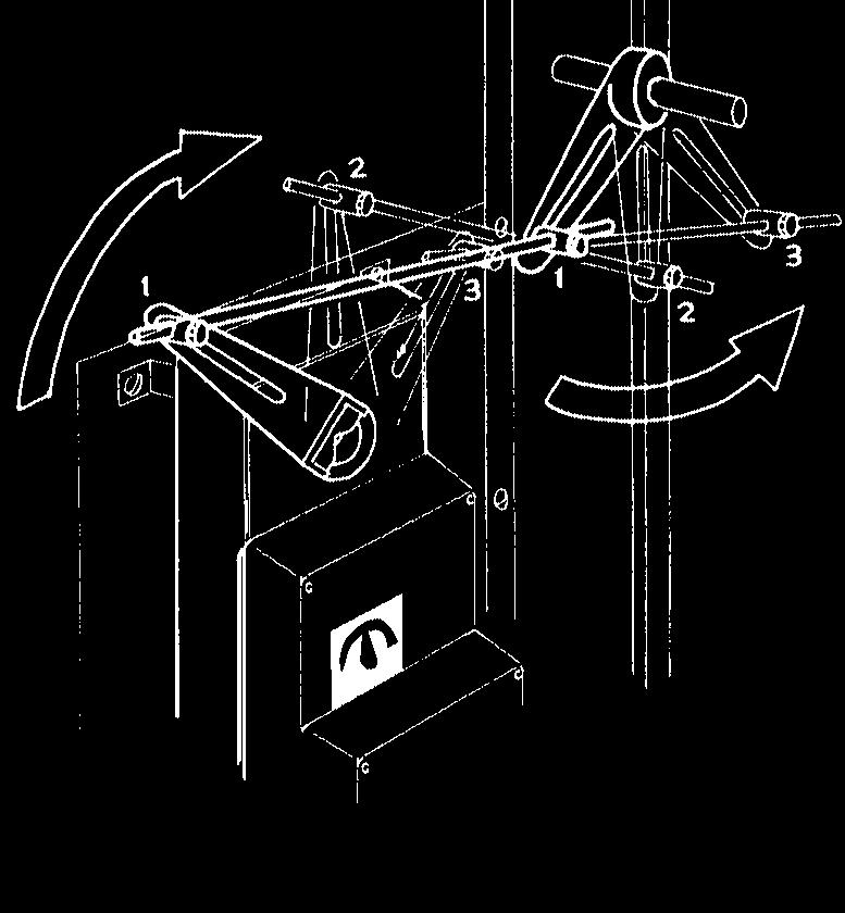
16 Section 3 - non-direct coupled applications Using universal mounting brackets with linkage Coupling DC1 Damper Clip Note: If 2 dampers are to be operated from a single actuator, torque distribution is optimized when the crankarm is positioned between the dampers as illustrated above. ZG-AF Linkage Kit Fig. 3.1 Actuator connected to 2 dampers that share the same shaft. ZG-DC1 bracket ZG-16 or ZG-17 Fig. 3.2 Universal mounting bracket is attached to damper assembly. Fig. 3.3 Attached to ductwork. Operated by linkage. ZG-DC2 bracket 16 Fig. 3.4 Using the ZG-DC2 bracket with the AF,NF type actuators
17 Using universal mounting brackets with linkage Section 3 - non-direct coupled applications AF/NF Actuator Fig. 3.5 AF or NF Series actuator mounted in the airstream using linkage using ZG-AF Crankarm Adaptor Kit For retrofit of new installation, pre-punched hole patterns place AF/NF crankarm (KH-AF) in same relative position as crankarm of Honeywell Mod III and Johnson Controls linkage-type actuators. Allows mounting actuator in horizontal or vertical orientation. For retrofit of new installation, pre-punched hole patterns place AF/NF crankarm (KH-AF) in same relative position as crankarm of Honeywell Mod III and Johnson Controls linkage-type actuators. Allows mounting actuator in horizontal or vertical orientation. Fig. 3.7 Using the ZG-18 Universal mounting bracket with AF/NF actuators AF/NF Actuator ZG-18 Fig. 3.6 Using the ZG-16, ZG-17 Universal mounting bracket Fig. 3.8 ZG-18 Universal mounting bracket. Here it is attached to a field-fabricated 16 ga. angle iron or plate. 17
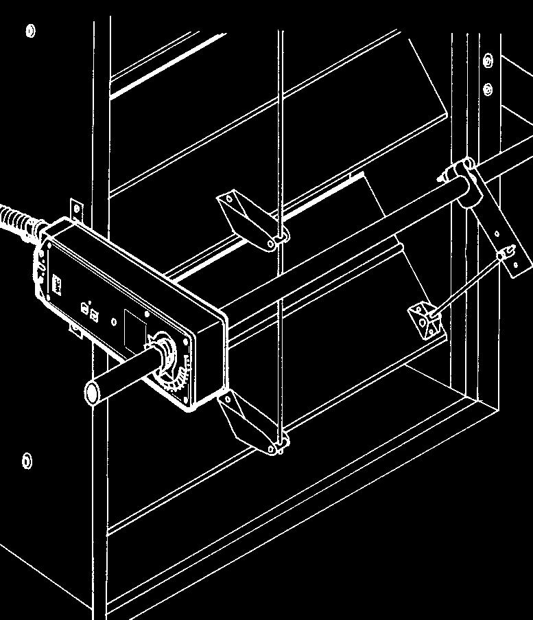
18 Section 3 - non-direct coupled applications Using universal mounting brackets with linkage ZG-1 ZG-14 Connect to jackshaft or standard shaft with linkage. Cut an appropriately sized hole through the mounting bracket to accommodate the common shaft. Attach actuators with machine screws, washers and locknuts. Wall mounting Fig Universal mounting bracket. Use linkage for connecting actuator to damper louvers. Fig. 3.9 For added torque, mount 2 actuators back-toback on a universal mounting bracket or field-fabricated plate. Use EMT tubing as a common shaft. ZG-11 Fig. 3.1 Actuator is mounted on universal mounting bracket or field-fabricated plate ZG-AF ZG-AF Fig Different ideas for attachment to walls. 18
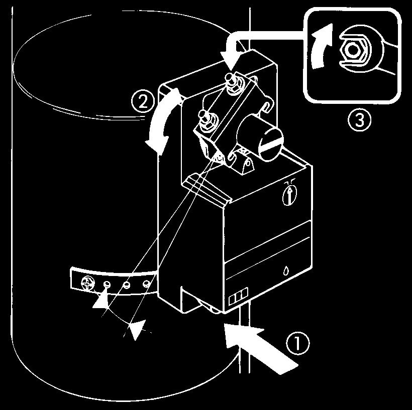
19 Using universal mounting brackets with linkage Section 3 - non-direct coupled applications NM24 NM24 ZG-NM3 ZG-15 Fig Universal mounting bracket or a field-fabricated 16 ga. angle iron or plate. Used when there is little clearance between the damper shaft and the wall. Fig Actuator mounted on a field-fabricated 16 ga. plate to control a cone-type VAV damper KH-8 Crankarm - final position must be vertical when damper is fully open. ZG-NM4 Mount actuator at a 45 angle to allow for full crankarm rotation. NM24 Damper is mounted through a wall with control shaft exposed, but space too tight to direct couple. Fig Use this method when there is little clearance between the damper shaft and the wall. 19
20 Section 3 - non-direct coupled applications non-direct mounting to jackshafts ZG-18 Existing crank arm as supplied by damper manufacturer Fig Actuator is mounted to damper assembly. Connect to jackshaft with linkage kit. For added strength, use an 18-2 ga. steel base plate, secured with sheet metal screws. Fig Actuator mounted to ductwork. For larger actuators such as the GM series, an added 18-2 ga. base plate for reinforcement is recommended. Connect actuator to jackshaft with linkage kit. Fig Actuator mounted to adjacent wall. Common channel iron is used here which allows for spacing the actuator away from wall. Connect actuator to jackshaft with linkage kit. 2 Jackshaft larger than 3/4 inch O.D. Fig Universal mounting bracket used to mount actuator to ductwork. Connect to jackshaft with linkage kit. ZG-11 Note: The full travel of the actuators must be used. Otherwise, the high force produced may damage the damper. 3/8 diameter rods must be used. Additional holes have been drilled in a ZG-11 bracket to allow mounting of the actuator. Fig. 3.2 Multiple actuator mounting. Universal mounting bracket is used to mount actuators. Connect actuators with linkage kits. This method allows you to easily meet higher torque requirements by simply increasing the number of actuators used.
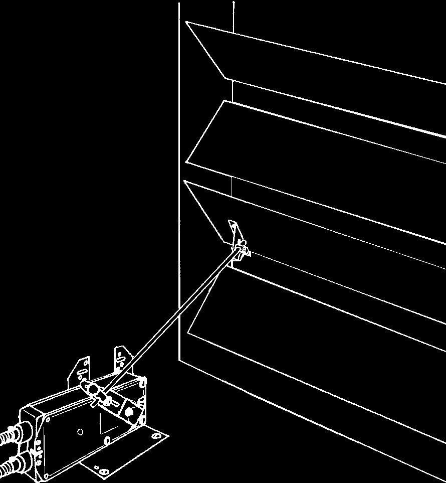
21 mounting to inlet vanes Section 3 - non-direct coupled applications Actuator 1 is mounted to vortex frame. and direct coupled to linkage shaft. 2nd actuator if needed Linkage is part of inlet vane assembly supplied by manufacturer. ZG-14 Fig Actuator is mounted to framework. Connect to inlet vanes with linkage. A second actuator may be mounted on the opposite side of the frame as needed. Fig Actuator is mounted to a universal mounting bracket or field-fabricated bracket. Connect to inlet vanes with linkage. ZG-14 Clamp mounted under actuator for short shaft mounting Fig Actuator is mounted to ductwork. Connect to inlet vanes with linkage. Fig Actuator is mounted to a universal mounting bracket or field-fabricated bracket. Connect to inlet vanes with linkage. 21
22 Section 4 - retrofit applications Replacing existing actuators SM24 GM24 ZG-13 ZG-14 NM24 ZG-15 NM24 ZG-15 SM24 GM24 ZG-14 AF NF AF NF ZG-16 ZG-17 ZG-17 AF NF AF NF AF NF ZG-18 ZG-18 Fig. 4.1 Different methods of using the universal mounting bracket to mount Belimo actuators in place of existing, less adequate actuators. 22
23 Tips for hook-up Section 5 - conduit connections Flexible Conduit Fig. 5.1 Standard electrical configuration Fig. 5.3 Connecting directly to junction box Drip Legs! Be sure stud of antirotation strap is positioned so that actuator doesn t fall off as it rotates from to. Test this with manual crank or gear release. Fig. 5.2 Spring Return Actuator -standard electrical configuration NOTE: Always use flexible counduit at the actuator. Incorporate drip legs whenever actuator in mounted upside down to prevent moisture from running dow flex and into actuator. Fig. 5.4 Spring Return Actuator - connected directly to junction box 23
24 Section 6 - Damper linkages Important information GENERAL INFORMATION The direct coupled method of mounting an actuator to a damper should be used whenever possible. It is the most effective way to mount an actuator from a time, required space, and force transmission stand point. However, there are some applications where a linkage must be used along with, or in place of, the direct coupled method. When using any linkage setup, it is important that the proper geometry be used. If the geometry is not correct, several problems can occur. Some of which are: a risk of binding, incorrect rotation at the damper, the full available torque may not be utilized, or excessive wear to the linkage parts or actuator. It is possible to arrange the linkage in such a way that special functions can be provided. For example, the torque provided to the damper can be modified so that less torque is provided in the open position of a damper, but more torque would be available for tight close off. The speed of rotation can be changed. The angle of damper rotation can be limited. General Guidelines 1. The ball joints should be placed as close to the end of the crank arm as possible. This will minimize the forces acting on the linkage parts and reduce any hysteresis in the linkage assembly. See figure Always use the full rotation of the actuator. If the damper rotation is complete and the actuator is still rotating, the linkage may bind up. 5. Always check the operation of the linkage assembly to make sure it operates the damper properly between the fully open and fully closed damper position. Technical Information The definition of torque is that it is a turning force. When talking about torque from an engineering standpoint we talk about a force (F), acting on the length of an arm (L), producing a turning force (T) given in a unit which incorporates both a unit of length and force in its description. Looking at this as an equation we would have: T = L x F ; where in common applications L would be in inches, F would be in pounds, and T would be shown as inch-pounds or pound-inches Figure 6.3 shows a crank arm with a length between the pivot point to the ball joint attachment of 4 inches. At the ball joint it shows we are applying a force of 25 pounds. The resulting torque would be 1 in-lb. A 2. The distance from the center of rotation of the crank arm to the ball joint should be the same for both crank arms. This provides uniform rotation at both crank arms. See figure The push rod and crank arms should be set up so the crank arms on both the actuator and damper rotate 45 degrees from a line perpendicular from the rod to the center of the crank arm rotation. This provides a balanced torque load to the damper and minimizes any chance of the linkage binding. See figure 6.2. A=B Fig. 6.1 Fig. 6.2 B 45 L = 4 in. T = L x F = 4 in x 25 lb = 1 in-lb When using this equation with actuators it is more common to see it in the following forms: F = T / L Fig. 6.3 F = 25 lb. or L = T / F The rating of most electronic actuators is given in torque and it is usually required to find either the force from the crank arm or the length of the crank arm for the application. In figure 6.3, if we said the actuator had a torque of 1 in-lb, and needed a force of 25 lb, we would need a 4 inch crank arm. L = T / F = 1 in-lb / 25 lb = 4 in Unfortunately, the equation T = L x F is only correct when the force acts upon the crank arm at a angle. At any angle other than the resultant torque or force is dependent on the crank arm effective radius. The effective radius (R), shown in figure 6.4, is the distance between the point on the push rod which is perpendicular to the center of rotation of the crank arm and the center of rotation. 24
25 Important information Section 6 - Damper linkages L=4 in. Fig. 6.4 F = 5 lb. R = 2 in. the actuator is actually multiplied at this point by a factor M which is equal to Rd/Ra. M = Rd / Ra One important thing to remember is that at the opposite end of rotation the torque can be reduced to a point where minor binding or friction could lock up the damper. Faster Response Time At Damper We now have to substitute the effective radius (R) in place of the crank arm length (L) in the torque equation. T = R x F or F = T / R Note: R has its greatest value at the point where the crank arm is perpendicular to the push rod. At this point R equals L. Figure 6.4 shows the same torque and crank arm as figure 6.3; however, the crank arm is now not perpendicular to the push rod. At this point in the crank arm rotation we show an R of 2 inches. With the output torque of 1 in-lb, the resulting force at this point is 5 lb. F = T / R = 1 in-lb / 2 in. = 5 lb As the effective radius (R) changes during the crank arm rotation, the relationship between torque, force, and even rotational speed changes. By analyzing the crank arm orientation between the actuator and damper, special set ups can be made to optimize certain damper applications. High Close Off Torque SPECIAL APPLICATIONS Low leakage dampers with blade seals require a greater closeoff torque than the normal operating torque. By setting up the linkage correctly, the torque provided to the damper at closeoff can be multiplied. closed R d Damper open Fig. 6.5 Figure 6.5 shows a linkage arrangement where, when the damper is in the closed position, the angle between the actuator crank arm and push rod is relatively large. This angle makes the resulting effective radius at the actuator (Ra) small; this in turn causes a higher force to act on the push rod. When the damper is at close-off, the damper crank arm is adjusted so it is at an angle creating a relatively large effective radius (Rd) at the damper. The large force from the push rod is multiplied by the effective radius (Rd) at the damper and the result is a higher torque at the close off position. The torque from R a Actuator closed Damper open Figure 6.6 shows an application where the actuator crank arm is approximately twice as long as the damper crank arm. This results in a rotation at the damper shaft of with only 45 of rotation at the actuator. Using only 45 of the actuator s rotation gives the advantage of the damper operating at twice the actuator s normal speed. A draw back is that the actuator torque is cut in half. It is recommended that the actuator be limited to only 45 of rotation either mechanically (preferred) or electrically. If this is not done, it is possible that the linkage or the damper may be damaged as the actuator continues to rotate. Limiting Damper Rotation closed Damper open Fig 6.7 shows an application where we are limiting the degree of rotation while still using the full rotation of the actuator. The crank arm shown of the actuator is shorter than the arm on the damper. Because of the smaller arc produced at the actuator arm, the push rod travel cannot rotate the damper arm through a full rotation. General Comments Fig. 6.6 Fig. 6.7 Actuator The use of a linkage assembly can be advantageous if a solution to a special need is required. However, great care must be taken in planning the linkage geometry. Any change made to the linkage has an effect on more than one condition. As an example, if you adjust the linkage for more torque, you will at the same time effect the damper rotational speed and the angle of the damper rotation. In any special application it is necessary to use a trial-and-error, back-and-forth method to set the required parameters. This can be a very time consuming process, but it should be done. 45 Actuator 25
26 Section 6 - Damper linkages Applications using linkages OPEN Fig. 6.8 Back-to-Back: The Easiest Method of Increasing Break-away Torque (1) is the start point; (3) is the end point. Damper movement is slowest from positions (1) to (2) and increases in speed to position (3). For example: If a in-lb actuator is used, torque at position (1) is approximately 1 in-lb while torque at position (3) is approximately 45 in-lb. Thus, greatest torque is supplied where it is needed most - at the beginning of the damper s movement to assure break-away from the side seals. Fig. 6.9 Typical Parallel Crankarm Operation Here, both crankarms remain parallel throughout the complete arc of movement, ensuring consistent torque at all times. This is one of the most common methods of mounting using linkage. Fig. 6.1 Over-and-Under Here, the crankarms are set in opposite directions. This method is used in situations where space is limited. 26
27 Notes/Work Pad 27

28 VOL Actuators for heating, ventilation, air-conditioning Print Documentation Overview Company Profile Product Guide and Price List Product Documentation Spring Return Actuators AF Series, 133 in-lb NF Series, in-lb LF Series, 35 in-lb Non-Spring Return Actuators GM Series, 266 in-lb AM Series, 1 in-lb NM Series, in-lb LM Series, 35 in-lb Control Valves Characterized Control Valves NV Series Actuator, Globe Valves ( 1 /2-2 ) Flanged Globe Valves (2 1 /2-6 ) Zone Valves Butterfly Valves Multi-Function Technology Accessories Electronic Mechanical Reference Mounting Wiring Damper Applications Valve Applications Sizing and Selections Submittals News Belimo Direct Product Newsletter Belimo Feedback Application Newsletter Electronic Documentation Simply the best way to drive a damper PRODUCT CATALOG ACTUATOR SELECTION SOFTWARE Complete product catalog and selection tools for damper actuators and control valves at or on CD-ROM. Serving HVAC Professionals Throughout the Americas Belimo Aircontrols (USA), Inc. Corporate Headquarters/Manufacturing Distribution/Customer Service Center Latin American Customer Service 43 Old Ridgebury Road, P.O. Box 2928 Danbury, CT 6813 () (23) Fax (23) Toll free fax order line: 1--ACTUATE ( ) Belimo Aircontrols (USA), Inc. Distribution/Customer Service Center 1675 East Prater Way, Suite 11 Sparks, NV () (775) Fax (775) Toll free fax order line: Belimo Aircontrols (CAN), Inc. Corporate Headquarters Distribution/Customer Service Center 14/ Coopers Avenue Mississauga, Ontario L4Z 2E8 (5) Fax (5) Belimo Servomoteur, Inc. Corporate Headquarters Customer Service Center 27 Chemin Du Lac Longueuil, Québec J4N 1B8 (45) Fax (45) 928
AF Series Spring Return Direct Coupled Actuator
 AF Series Spring Return Direct Coupled Actuator Minimum in-lb torque For damper areas up to sq-ft* (For lower torque, see NF or LF series) Applications Direct Coupling - The Belimo Concept Remove for /
2006 Product Range Overview. Belimo Project: One Bellevue Center, Seattle, Washington
 2006 Product Range Overview Belimo Project: One Bellevue Center, Seattle, Washington Actuator Product Range Spring Return TF 18 in-lb [2 Nm] Approx. 4.5 sq. ft. LF 35 in-lb [4 Nm] Approx. 8 sq. ft. NF
GMX On/Off-Floating Point Control, Non-Spring Return, Direct Coupled, 100 to 240 VAC
 On/Off-Floating Point Control, Non-Spring Return, Direct Coupled, 00 to 40 VAC Torque min. 60 in-lb for control of damper surfaces up to 90 sq ft. Application For on/off and floating point control of dampers
AMB24-3(-S) On/Off-Floating Point Control, Non-Spring Return, Direct Coupled, 24 V
 On/Off-Floating Point Control, Non-Spring Return, Direct Coupled, 24 V") AMB-(-S) On/Off-Floating Point Control, Non-Spring Return, Direct Coupled, V Torque min. 80 in-lb for control of damper surfaces up to 5 sq ft. Application For on/off and floating point control of dampers
AMB-(-S) On/Off-Floating Point Control, Non-Spring Return, Direct Coupled, V Torque min. 80 in-lb for control of damper surfaces up to 5 sq ft. Application For on/off and floating point control of dampers
GMX24-SR. Proportional Control, Non-Spring Return, Direct Coupled, 24V, for 2 to 10 VDC and 4 to 20 ma
 Proportional Control, Non-Spring Return, Direct Coupled, 4V, for to 0 VDC and 4 to 0 ma Torque min. 360 in-lb for control of damper surfaces up to 90 sq ft. Application For proportional modulation of dampers
LF Series Spring Return Direct Coupled Actuator
 LF Series Spring Return Direct Coupled Actuator Minimum in-lb torque LF actuator For damper areas up to 8 sq-ft* Applications Cost effective quality and performance for a range of applications including:
LMX120-SR. Proportional Control, Non-Spring Return, Direct Coupled,100 to 240 VAC, for 2 to 10 VDC and 4 to 20 ma
 LMX0-SR Proportional Control, Non-Spring Return, Direct Coupled,00 to 0 VAC, for to 0 VDC and to 0 ma Torque min. 5 in-lb for control of damper surfaces up to sq ft. Application For proportional modulation
Dimensions [All numbers in brackets are in millimeters.] K4-2 US (supplied) 1/2" Centered (Default) 3/4" Centered (Field Selectable)
![Dimensions [All numbers in brackets are in millimeters.] K4-2 US (supplied) 1/2 Centered (Default) 3/4 Centered (Field Selectable)](/thumbs/75/72188842.jpg "Dimensions [All numbers in brackets are in millimeters.] K4-2 US (supplied) 1/2 Centered (Default) 3/4 Centered (Field Selectable)") NF24-SR (-S) US Proportional Damper Actuator, Spring Return Fail-Safe, 24 V for 2 to 1 VDC, or 4 to ma Control Signal. Output Signal of 2 to 1 VDC for Position Indication Torque min. 6 in-lb, for control
NF24-SR (-S) US Proportional Damper Actuator, Spring Return Fail-Safe, 24 V for 2 to 1 VDC, or 4 to ma Control Signal. Output Signal of 2 to 1 VDC for Position Indication Torque min. 6 in-lb, for control
FSAF24(-S) US, FSAF120(-S) US
 US, FSAF120(-S) US") FSAF4(-S) US, FSAF10(-S) US On/Off, Spring Return, Meets 50 F [11 C] for Half Hour, 75 Seconds Torque min. 133 in-lb, for control of air dampers Technical Data FSAF4(-S) US, FSAF10(-S) US Power supply
FSAF4(-S) US, FSAF10(-S) US On/Off, Spring Return, Meets 50 F [11 C] for Half Hour, 75 Seconds Torque min. 133 in-lb, for control of air dampers Technical Data FSAF4(-S) US, FSAF10(-S) US Power supply
Belimo is the Worldwide Leader in Fire and Smoke Actuation
 FS Series Fire and Smoke Direct Coupled Actuators Belimo is the Worldwide Leader in Fire and Smoke Actuation Gateway Base II, Hong Kong Belimo first produced actuators for the European fire and smoke damper
LMB24-3 (-S)(-T) On/Off-Floating Point Control, Non-Spring Return, Direct Coupled, 24 V
(-T) On/Off-Floating Point Control, Non-Spring Return, Direct Coupled, 24 V") LMB- (-S)(-T) On/Off-Floating Point Control, Non-Spring Return, Direct Coupled, V Torque min. 5 in-lb for control of damper surfaces up to sq ft. Technical Data LMB- on/off-floating Power Supply VAC ±
LMB- (-S)(-T) On/Off-Floating Point Control, Non-Spring Return, Direct Coupled, V Torque min. 5 in-lb for control of damper surfaces up to sq ft. Technical Data LMB- on/off-floating Power Supply VAC ±
Minimum 90 in-lb Torque. Applications. NFB, NFX Series At A Glance. NFB and NFX Series Spring Return Direct Coupled Actuator
 NFB and NFX Series Spring Return Direct Coupled Actuator Minimum 90 in-lb Torque For damper areas up to sq-ft* Applications 1 3/4 1/ New standard clamp fits standard 1/ shafts to 1.05 jackshafts. Mount
LMCB24-SR LMCB24-SR-T. applications. Dimensions (All numbers in brackets are in millimeters.) 1/4 to 3/4 [6 to 20] 5/16 to 3/4 [8 to 26] 1.
![LMCB24-SR LMCB24-SR-T. applications. Dimensions (All numbers in brackets are in millimeters.) 1/4 to 3/4 [6 to 20] 5/16 to 3/4 [8 to 26] 1.](/thumbs/95/124319282.jpg "LMCB24-SR LMCB24-SR-T. applications. Dimensions (All numbers in brackets are in millimeters.) 1/4 to 3/4 [6 to 20] 5/16 to 3/4 [8 to 26] 1.") LMCB4-SR (-T) Proportional Control, Non-Spring Return, Direct Coupled, 4V, for to 0 VDC and 4 to 0 ma Torque min. 45 in-lb for control of damper surfaces up to sq ft. LMCB4-SR LMCB4-SR-T HALOMO Brushless
LMCB4-SR (-T) Proportional Control, Non-Spring Return, Direct Coupled, 4V, for to 0 VDC and 4 to 0 ma Torque min. 45 in-lb for control of damper surfaces up to sq ft. LMCB4-SR LMCB4-SR-T HALOMO Brushless
Mount directly to 1.05 jackshafts. AF230 US (p. 02) AF230-S US (p. 20) AF24-S US (p. 18)
 AF230-S US (p. 20) AF24-S US (p. 18)") AF Series Spring Return Direct Coupled Actuator Minimum 133 in-lb torque For damper areas up to 35 sq-ft* (For lower torque, see NF, LF, or TF series) Applications Remove for 3/4 to 1.05 shafts ZG106 or
AF Series Spring Return Direct Coupled Actuator Minimum 133 in-lb torque For damper areas up to 35 sq-ft* (For lower torque, see NF, LF, or TF series) Applications Remove for 3/4 to 1.05 shafts ZG106 or
GM Series Direct Coupled Actuator
 GM Series Direct Coupled Actuator Minimum 3 in-lb torque** For damper areas up to 8 sq-ft* Applications Linkage is part of inlet vane assembly supplied by manufacturer. Actuator is mounted to vortex frame.
NMB (X) 24-MFT. Proportional Control, Non-Spring Return, Direct Coupled, 24V, Multi-Function Technology
 24-MFT. Proportional Control, Non-Spring Return, Direct Coupled, 24V, Multi-Function Technology") NMB (X) -MFT Proportional Control, Non-Spring Return, Direct Coupled, V, Multi-Function Technology Torque min. 90 in-lb for control of damper surfaces up to sq ft. Technical Data NMB(X)-MFT Power Supply
NMB (X) -MFT Proportional Control, Non-Spring Return, Direct Coupled, V, Multi-Function Technology Torque min. 90 in-lb for control of damper surfaces up to sq ft. Technical Data NMB(X)-MFT Power Supply
ZG106 or ZG 107 bracket
 NF Series Spring Return Direct Coupled Actuator Minimum 60 in-lb torque For damper areas up to 15 sq-ft* Applications K4-1 US Clamp ZG106 or ZG 107 bracket Mount directly to 1.05 jackshafts with accessory
AF Series Spring Return Direct Coupled Actuator
 AF Series Spring eturn Direct Coupled Actuator Minimum in-lb torque For damper areas up to 5 sq-ft* (For lower torque, see NF, LF, or TF series) Applications emove for / to.5 shafts ZG6 or ZG 7 bracket
NFB24, NFB24-S, NFX24, NFX24-S On/Off, Spring Return, 24 V
 NFB4, NFB4-S, NFX4, NFX4-S On/Off, Spring Return, 4 V Torque min. 90 in-lb, for control of air dampers Technical Data Power supply Power consumption Transformer sizing Electrical connection NFB4... NFX4...
Mounting Installation Instructions NKQ, GK
 7-0000.B Mounting Installation Instructions NKQ, GK General Information Preliminary steps. Belimo actuators with NEMA ratings should be mounted indoors in a dry, relatively clean environment free from
Versatile and Powerful
 AM Series Direct Coupled Actuator Versatile and Powerful Minimum 180 in-lb torque in a compact package. For damper areas up to 45 sq-ft* All Actuators have BDCM AM Series - At A Glance AMB(X)24-3 (p. 148)
NMQB24-MFT, NMQX24-MFT Quick Proportional Control, Non-Spring Return, Direct Coupled, 24V, Multi-Function Technology
 NMQB-MFT, NMQX-MFT Quick Proportional Control, Non-Spring Return, Direct Coupled, V, Multi-Function Technology Application For proportional modulation of dampers in HVAC systems. Actuator sizing should
LF Series Spring Return Direct Coupled Actuator
 LF Series Spring Return Direct Coupled Actuator Minimum in-lb torque For damper areas up to 8 sq-ft* LF actuator Applications Cost effective quality and performance for a range of applications including:
Mounting Installation Instructions ZG-JSL(A)
") 70756-00001.B Mounting Installation Instructions ZG-JSL(A) Preliminary Steps 1. Verify all the parts listed before installing the linkage. 2. Choose an actuator from one of the series listed below. There
70756-00001.B Mounting Installation Instructions ZG-JSL(A) Preliminary Steps 1. Verify all the parts listed before installing the linkage. 2. Choose an actuator from one of the series listed below. There
AMB24-3(-S) On/Off-Floating Point Control, Non-Spring Return, Direct Coupled, 24 V
 On/Off-Floating Point Control, Non-Spring Return, Direct Coupled, 24 V") AMB4-3(-S) On/Off-Floating Point Control, Non-Spring Return, Direct Coupled, 4 V Torque min. 80 in-lb for control of damper surfaces up to 45 sq ft. Application For on/off and floating point control of
AMB4-3(-S) On/Off-Floating Point Control, Non-Spring Return, Direct Coupled, 4 V Torque min. 80 in-lb for control of damper surfaces up to 45 sq ft. Application For on/off and floating point control of
Torque min. 35 in-lb, for control of air dampers
 LF-SR (-S) US Proportional Damper Actuator, Spring Return Fail-Safe, V for to VDC, or to ma Control Signal. Output Signal of to VDC for Position Indication. Torque min. 35 in-lb, for control of air dampers
M Remote Mounting Kit
 M9203-250 Remote Mounting Kit Installation Instructions M9203-250 Part No. 34-636-2324, Rev. Issued July 6, 2011 Applications The M9203-250 Remote Mounting Kit enables the M9203 Series Electric Spring
ZG-JSL, ZG-JSLA Jackshaft Retrofit Linkage For AF, NF, LF, NMX and AMX Series Actuators
 ZG-JSL, ZG-JSLA Jackshaft Retrofit Linkage For AF, NF, LF, NMX and AMX Series Actuators The ZG-JSL jackshaft linkage is designed to easily attach to any part of a jackshaft and allow easy installation
Minimum 18 in-lb Torque. Applications. TF Series At A Glance. TF Series Spring Return Direct Coupled Actuator. For damper areas up to 4.
 TF Series Spring Return Direct Coupled Actuator Minimum 18 in-lb Torque For damper areas up to 4.5 sq-ft* Applications Cost effective quality and performance for a range of applications including: Classroom
Table of Contents PAGE General Mounting Standard Reversible Clamp Linear Rotary Retrofit Brackets...275
 Installation and Operation Non-Spring Return General Information Table of Contents PAGE General Mounting Standard...7 Reversible Clamp...7 Linear...7 Rotary...73 Retrofit Brackets...75 Operation Electrical...76
Versatile and Powerful
 LM Series Direct Coupled Actuator Versatile and Powerful Minimum 45 in-lb torque in a compact package. For damper areas up to 11 sq-ft* Actuators in bold have BDCM LM Series - At A Glance LMB(X)24-3(-S)(-T)
Spring Achieve System Balance Without All The Spin. PICCV. Complete Details Inside!
 Spring 2005 Achieve System Balance Without All The Spin. PICCV Complete Details Inside! Valve Selection Has Never Been Easier! Simply choose the smallest PICCV that can satisfy the flow rate of your system.
Mount directly to 1.05 jackshafts. (new ZG-120 bracket shown) EFB24-S N4, EFX24-S N4(H) EFB24-S, EFX24-S (p. 21)
 EFB24-S N4, EFX24-S N4(H) EFB24-S, EFX24-S (p. 21)") EFB and EFX Series Spring Return Direct Coupled Actuator Minimum 70 in-lb Torque For damper areas up to 66 sq-ft* (For lower torque, see AFB, AF, NFB, LF, or TF series) Applications New standard clamp
EFB and EFX Series Spring Return Direct Coupled Actuator Minimum 70 in-lb Torque For damper areas up to 66 sq-ft* (For lower torque, see AFB, AF, NFB, LF, or TF series) Applications New standard clamp
D-4070 Two Stage Pneumatic Actuator
 FANs 268.1, 1628.3 Product/Techncial Bulletin D4070 Issue Date 1095 D-4070 Two Stage Pneumatic Actuator The D-4070 Two Stage Pneumatic Actuator is a multipurpose positioning device used to accurately position
Installation Instructions
 Quick-Mount Visual Instructions for Mechanical Installation Quick-Mount Visual Instructions 1. Rotate the damper to its failsafe position. If the shaft rotates counterclockwise, mount the CCW side of the
MC-351, 421, 431, MC-4311
 MC-35, 42, 43, MC-43 Three-Wire, Two Position Actuators General Instructions Applications For two-position operation of dampers or valves in heating, ventilating and air-conditioning systems and similar
LMX24-3 (-T) On/Off-Floating Point Control, Non-Spring Return, Direct Coupled, 24 V
 On/Off-Floating Point Control, Non-Spring Return, Direct Coupled, 24 V") LMX4- (-T) On/Off-Floating Point Control, Non-Spring Return, Direct Coupled, 4 V Torque min. 45 in-lb for control of damper surfaces up to sq ft. LMX4- LMX4--T Application For on-off and floating point
LMX4- (-T) On/Off-Floating Point Control, Non-Spring Return, Direct Coupled, 4 V Torque min. 45 in-lb for control of damper surfaces up to sq ft. LMX4- LMX4--T Application For on-off and floating point
Installation Instructions
 Quick-Mount Visual Instructions for Mechanical Installation Quick-Mount Visual Instructions. Rotate the damper to its failsafe position. If the shaft rotates counterclockwise, mount the CCW side of the
LF Series At A Glance
 LF Series Spring Return Direct Coupled Actuator Minimum 35 in-lb Torque For damper areas up to 8 sq-ft* Applications Cost effective quality and performance for a range of applications including: Classroom
Actuators for heating, ventilation, air conditioning 2. LF-2 -CD. Product Information Damper actuators with spring return.
 Actuators for heating, ventilation, air conditioning 2. F-2 -CD Product Information Damper actuators with spring return F i6772 Contents Selection table orque 4 Nm F24 F24-S F23 F23-S F24-3 F24-S Nominal
Minimum 27 in-lb torque
 LU Series Actuator Minimum 27 in-lb torque For damper areas up to 6.8 sq-ft* All Actuators have BDCM LU Series - At A Glance LUB(X)24-3 (p. 258) LUB(X)24-SR (p. 260) LUX24-MFT (p. 262) Basic Product Flexible
AF24-MFT95 US Proportional Damper Actuator, Spring Return Fail-Safe, 24 V for Use with Honeywell Electronic Series 90, or a 0 to 135Ω input
 AF-MFT9 US Proportional Damper Actuator, Spring eturn Fail-Safe, V for Use with Honeywell Electronic Series 9, or a to Ω input Torque min. in-lb Control fixed, to Ω input, or Honeywell series 9 (fixed)
Control Dampers and Fire Dampers. Volume 1 - March Insulated Control Dampers. Non-Insulated Control Dampers. Framing. Accessories.
 Insulated Control Dampers 2 Volume 1 - March 2010 6 Non-Insulated Control Dampers 8 Framing Accessories 9 Jack Shaft Steel Control Dampers Fire Dampers 10 11 Control Dampers and Fire Dampers 3900 Insulated
AM-676, AM , AM-690-R, AM-692, AM-693-R, AM-762, and AM-763
 [ Installation Instructions ] AM-676, AM-686...689, AM-690-R, AM-692, AM-693-R, AM-762, and AM-763 General Instructions for SmartX Accessories Applications The AM-676 universal shaft extension extends
SECTION CONTROL DAMPERS
 SECTION 23 09 13.43 - CONTROL DAMPERS PART I - GENERAL 1.1 SECTION INCLUDES A. Airfoil Dampers, Heavy Duty Galvanized Steel B. Thermally Insulated Dampers, Heavy Duty Galvanized Steel C. Airfoil Dampers,
Mounting Installation Instructions LM, NM, AM, GM
 709-0000 Rev G Mounting Installation Instructions LM, NM, AM, GM General Information Preliminary steps. Belimo actuators with NEMA or NEMA ratings should be mounted indoors in a dry, relatively clean environment
POWERS Controls. Technical Instructions Document No P25 AP December 3, No. 6 Pneumatic Damper Actuator.
 POWERS Controls No. 6 Pneumatic Damper Actuator Technical Instructions AP 331-3 331-2793 Actuator 331-2857 Actuator with Clevis and Pin 331-3012 Extended Shaft and Frame Mounting Description The POWERS
MA40-704X Series MA41-707X Series MA41-715X Series
 MA4-74X Series MA4-77X Series MA4-75X Series SmartX Actuators Spring Return Two-Position General Instructions Application SmartX Direct Coupled Actuators are designed to be used in both damper and valve
Valve Retrofit Installation Instructions for use with Electronic Actuators
 Valve Retrofit Installation Instructions for use with Electronic Actuators Effective February 2010 Belimo Project: New York Times Building, New York Get It All. Get It Here. Precision Superior functionality
Installation Instructions
 Quick-Mount Visual Instructions for Quick-Mount Visual Instructions 1. Rotate the damper to its failsafe position. If the shaft rotates counterclockwise, mount the CCW side of the actuator out. If it rotates
Minimum 27 in-lb Torque
 LU Series Actuator Minimum 27 in-lb Torque For damper areas up to 6.8 sq-ft* Actuators in bold have BDCM LU Series - At A Glance LUB(X)24-3 (p. 351) LUX120-3 (p. 353) LUB(X)24-SR (p. 355) LUX120-SR (p.
Accessories. Technical Data Extension Height 2" Material. Stainless Steel. Bearing TR LRB (X) ARB (X) TF LF AF. Extension Bracket CCV-EXT-Kit
 ARB (X) TF LF AF. Extension Bracket CCV-EXT-Kit") The CCV-EXT-KIT can be used with most CCV s* and PICCV in order to achieve a large clearance over the pipe. The Extension Kit will provide an additional 2 of space between the top of the valve and the
The CCV-EXT-KIT can be used with most CCV s* and PICCV in order to achieve a large clearance over the pipe. The Extension Kit will provide an additional 2 of space between the top of the valve and the
M Damper Mount Linkage Kit Installation. Item Description Quantity Item Description Quantity Nuts 2
 FANs 268.1, 1628.3 Installation Bulletin M9000-150 Issue Date 0796 M9000-150 Damper Mount Linkage Kit Installation 21 18 19 20 2 22 17 2 4 3 2 15.5 393.7 1 17 16 15 11 13 12 8 9 10 2 5 Note: Damper mount
SMOKE DAMPERS SMOKE DAMPERS SMOKE DAMPERS
 SMOKE DAMPERS 96 97 SD SERIES SD for Use in Dynamic Systems Types Galvanized Steel Construction as Standard.. Sleeve Type, Model: SD - 0-00. Circular Type, Model: SD - 50-00. Oval Type, Model: SD - 60-00
Introduction to Johnson Controls Dampers
 Damper and Actuator Product Guide 268.1 Damper Engineering Section Product Bulletin Issue Date 1297 Introduction to Johnson Controls Dampers For over 100 years, Johnson Controls has been the industry leader
AM Series Direct Coupled Actuator
 AM Series Direct Coupled Actuator Versatile and Powerful Minimum 60 in-lb torque in a compact package. For damper areas up to 0 sq-ft*. Areas of Application Direct Coupled up to / standard shafts or Jackshafts
Butterfly Valve Retrofits
 Butterfly Valve Retrofits Contents How to Select the Butterfly Retrofit Solution... pg 127 Butterfly Valve Retrofit Actuators... pg 128 Solutions for Specific Manufacturer and Part Number Apollo... pg
AFXUP-S (p. 19) AFB24-MFT. AFXUP (p. 19) AFBUP-S
 AFB24-MFT. AFXUP (p. 19) AFBUP-S") AF and AFX Series Spring eturn Direct Coupled Actuator Minimum 180 in-lb Torque For damper areas up to 4 sq-ft* (For lower torque, see AF, NF, NFX, LF, or TF series) Applications 1 3/4 1/2 New standard
AF and AFX Series Spring eturn Direct Coupled Actuator Minimum 180 in-lb Torque For damper areas up to 4 sq-ft* (For lower torque, see AF, NF, NFX, LF, or TF series) Applications 1 3/4 1/2 New standard
POWERS Controls No. 4 Pneumatic Damper Actuator
 POWERS Controls No. 4 Pneumatic Damper Actuator Technical Instructions Document No. 155-032P25 AP 331-2 Actuator Assembly 331-2929 Typical Actuator Assembly 331-2904 Typical Actuator Assembly 331-3000
Damper Actuator Installation
 FANs 268.1, 977, 1628.3 Installation Bulletin EPP-1000 Issue Date 0800 EPP-1000 Series Electro-Pneumatic Positioners A pplication The EPP-1000 is designed for applications where electronic control of pneumatic
MODELS TSX AND TSX-S SINGLE DUCT ROUND AIR TERMINALS
 MODELS TSX AND TSX-S SINGLE DUCT ROUND AIR TERMINALS INSTALLATION OPERATION & MAINTENANCE New Release Form 130.13-NOM4 (908) In conjunction with the use of these instructions, obtain and refer to the construction,
Globe Valve Retrofits
 Globe Valve Retrofits Contents How to Select the Globe Valve Retrofit Solution... pg 33 Globe Valve Retrofit Actuators... pg 34 Solutions for Specific Manufacturer and Part Number Honeywell... pg 37 Johnson
LF24-ECON-R03(-R10) US Operation, Installation and Wiring
 US Operation, Installation and Wiring") LF24-ECON-R03(-R0) US Operation, Installation and Wiring Operation LF24-ECON-R03(-R0) US The LF24-ECON-R03(-R0) US provides a direct coupling solution for RoofTop Unit(RTU) economizer dampers. Control
LF24-ECON-R03(-R0) US Operation, Installation and Wiring Operation LF24-ECON-R03(-R0) US The LF24-ECON-R03(-R0) US provides a direct coupling solution for RoofTop Unit(RTU) economizer dampers. Control
MODELS SGX AND SSX SINGLE DUCT ROUND AIR TERMINALS
 BY JOHNSON CONTROLS INSTALLATION OPERATION & MAINTENANCE MODELS SGX AND SSX SINGLE DUCT ROUND AIR TERMINALS New Release Form ET130.13-NOM4 (908) In conjunction with the use of these instructions, obtain
M Remote Mounting Kit
 M9208-250 Remote Mounting Kit Installation Instructions M9208-250 Part No. 34-636-2200, Rev. A Issued August 29, 2014 Applications IMPORTANT: Use this M9208-250 Remote Mounting Kit only to control equipment
EDA-8100 Electric Damper Actuator
 Installation Sheet Issue Date 0392 EDA-8100 Electric Damper Actuator Kit Includes 1. EDA-8100-1100 Electric Damper Actuator with counterclockwise spring return, or EDA-8100-1101 Electric Damper Actuator
Tube Axial Fan Page Specifications & Dimension Data Performance Data
 Tube Axial Fan Page Introduction........................................... 2 Construction Features................................... 3 Information........................................... 4 Specifications
NV Direct Coupled Globe Valve Actuator
 70396 Rev. C Non-spring return, on/off, floating point, proportional control NV Direct Coupled Globe Valve Actuator NV24-3 US NVD24-3 US NV24-MFT US NVD24-MFT US Application For on/off, floating point
MX4X-6XXX Series MX4X-7XXX Series. Selection Guide. Applications. DuraDrive Series Actuators and Accessories
 MX4X-6XXX Series MX4X-7XXX Series Selection Guide DuraDrive Series Actuators and Accessories Applications DuraDrive Direct Coupled Actuators are designed to accept two-position, floating, or proportional
Butterfly Valve Retrofits
 Butterfly Valve Retrofits Contents How to Select the Butterfly Retrofit Solution... pg 127 Butterfly Valve Retrofit Actuators... pg 128 Solutions for Specific Manufacturer and Part Number Apollo... pg
Installation, Operation, and Maintenance Manual. Automatic Fire Damper
 Installation, Operation, and Maintenance Manual Automatic Fire Damper Part # 458295 Designed to close in fire situations. Reset by activating the reset switch. UL Listed Constructed in Accordance with
MAx-305 & MAx-318 Series MAx-405 Through MAx-419 Series Two-Position Actuators
 MAx-305 & MAx-38 Series MAx-405 Through MAx-49 Series Two-Position Actuators General Instructions Application For two-position operation of dampers, valves, and other equipment which require the return
Damper Applications Guide
 Actuators for heating, ventilation, air-conditioning Damper Applications Guide Constant Volume Damper and Actuator Characteristics 5.3 EA FAN FLOW % 9 IDEAL FUNCTION TOTAL FLOW 8 ACTUATORS 7 Heating/Cooling
BELIMO CONTROLS
 INDEX ACCESSORIES MECHANICAL CRANK ARM ADAPTOR KITS... 7-17 JACKSHAFT LINKAGE FOR SPRING RETURN DAMPER ACTUATORS... 7-17 MISCELLANEOUS... 7-17 MOUNTING BRACKETS... 7-17 DAMPER ACTUATORS FIRE AND SMOKE
 1 TAMCO ALUMINUM CONTROL DAMPER Installation Guidelines For Series 1000, 1400, 1500, 9000, 9000 BF FOR TAMCO JACK SHAFTS REFER TO INSTRUCTIONS PROVIDED IN PARTS BOX. FOR TAMCO JUMPERS REFER TO INSTRUCTIONS
Dodge Engineering & Controls, Inc. Toll Free (877) Fax: (978) ES142 Spring Return Electronic Actuators
 Fax: (978) ES142 Spring Return Electronic Actuators") a EA0655R1 c b e f g d h a. Actuator b. Shaft adapter c. Position indicator d. Shaft adapter locking clip e. Position indicator adapter f. Mounting bracket (for dampers) g. Mounting screws h. 3 mm hex
a EA0655R1 c b e f g d h a. Actuator b. Shaft adapter c. Position indicator d. Shaft adapter locking clip e. Position indicator adapter f. Mounting bracket (for dampers) g. Mounting screws h. 3 mm hex
MA-5200 Series MA-5300 Series
 MA-5200 Series MA-5300 Series Two-Position Actuators General Instructions Application The MA-5200 series and MA-5300 series actuators are used for two-position control of valves and dampers which require
Globe Valve Retrofits
 Globe Retrofits Contents How to Select the Globe Retrofit Solution... pg 33 Globe Retrofit Actuators... pg 34 Solutions for Specific Manufacturer and Part Number Honeywell... pg 37 Johnson Controls...
Hose Length Custom Length Supply Line Options Ball Valve w/ PT UBY Strainer w/ PT and BDV
 Model AC Circuit Sentry Automatic Balance Hose Kits - Submittal Hose Kit Size Flow Range *MFR Qty. 1/2".33-14 5 3/4".33-14 11 3/4" 5-50 11 1".33-14 20 1" 5-50 20 1-1/4" 5-50 30 **1-1/2" 5-50 44 **1-1/2"
Spring Return and Double Acting Pneumatic Quarter-turn Actuators Operations Manual
 Spring Return and Double Acting Pneumatic Quarter-turn Actuators Operations Manual Table of Contents General..................... 1 Pneumatic Recommendations... 1 Construction................. 2 Disassembly
Accessories & Service Kits
 Table of Contents Accessories & Service Kits Product Page # OpenAir Electric Tools E-46 Damper Shaft Cranks E-46 Mounting Hardware E-47 Damper Push Rods E-47 Anti-rotation Brackets E-48 Shaft Adapters
CENTAXIAL TUBULAR CENTRIFUGAL FANS. BIA Airfoil Blade Design Direct Drive & Belt Driven Model CBD / CDD (Class I, II & III) Model CBD Belt Driven
 Model CBD Belt Driven") Model CBD Belt Driven Model CDD Direct Drive CENTAXIAL TUBULAR CENTRIFUGAL FANS BIA Airfoil Blade Design Direct Drive & Belt Driven Model CBD / CDD (Class I, II & III) CATALOG 337 February 2004 Centaxial
Model CBD Belt Driven Model CDD Direct Drive CENTAXIAL TUBULAR CENTRIFUGAL FANS BIA Airfoil Blade Design Direct Drive & Belt Driven Model CBD / CDD (Class I, II & III) CATALOG 337 February 2004 Centaxial
Fixed Pitch Vane Axial Fan
 Fixed Pitch Vane Axial Fan Page Introduction...........................................2 Construction Features...................................3 Mounting Options.......................................3
MS Series MS Series MS Series
 MS4-743 Series MS4-773 Series MS4-753 Series SmartX Actuators Spring Return Proportional General Instructions Application SmartX Actuators (Direct Coupled) are designed to be used in both damper and valve
Powers TM Controls EA 338 Electronic Actuator
 Powers TM Controls Technical Instructions Document No. 155-136P25 EA 338-1 Description Features 24 Vac power supply. The s are used with floor mount linkage kits to operate dampers in HVAC installations.
Switchback Carrier Rack System
 Switchback Carrier Rack System Installation Instructions 1 Rocky Mountain Westy Ph. (970)310-3441 Introduction Thank you for purchasing the Rocky Mountain Westy Switchback Carrier Rack System. We pride
SBH / SBV Sales Guide BLOWER-COILS HORIZONTAL AND VERTICAL
 SO TOUGH, WE GUARANTEE IT. SBH / SBV Sales Guide BLOWER-COILS HORIZONTAL AND VERTICAL SBH SBV www.superiorrex.com SO TOUGH, WE GUARANTEE IT! www.superiorrex.com SBH / SBV Series: CONSTRUCTION FEATURES
D690 Round Damper LOW-LEAKAGE, SINGLE-BLADE FEATURES APPLICATION PRODUCT DATA. Contents
 D690 Round Damper LOW-LEAKAGE, SINGLE-BLADE FEATURES PRODUCT DATA Neoprene and silicone seal for tight closing and low leakage. Oilite bearings for long life. 90-degree damper travel for a variety of applications.
MP-5400 Series. Application. Features. Applicable Literature. Electronic Positive Positioning Hydraulic Actuator General Instructions
 TAC 1354 Clifford Avenue P. O. Box 2940 Loves Park, IL 61132-2940 www.tac.com MP-5400 Series Electronic Positive Positioning Hydraulic Actuator General Instructions Application The MP-5400 Series Actuators
VA-908x Series Electric Rotary Actuators for Two-Position and Modulating Service
 VA-908x Series Electric Rotary Actuators for Two-Position and Modulating Service Installation Instructions VA-908x Code No. LIT-12011566 Issued August 24, 2009 Applications The VA-908x Series Electric
Globe Valve Retrofits
 Globe Valve Retrofits Contents How to Select the Globe Valve Retrofit Solution... pg 33 Globe Valve Retrofit Actuators... pg 34 Solutions for Specific Manufacturer and Part Number Honeywell... pg 37 Johnson
VF Series Standard-Pressure, Standard-Temperature Butterfly Valves
 Product Bulletin VF Series No. 2 Issue Date 11/01/01 VF Series Standard-Pressure, Standard-Temperature Butterfly s VF Series Standard-Pressure, Standard-Temperature Butterfly s are specifically designed
Bulletin ACF 103 AIRFOIL CENTRIFUGAL FANS DESIGN 10A
 Bulletin ACF 103 AIRFOIL CENTRIFUGAL FANS DESIGN 10A Quieter, More Efficient Airfoil Fans for Commercial and Light Industrial Applications Design 10A Fans with Airfoil Wheels Fourteen Sizes to 80" Volumes
BETTIS ACTUATOR & CONTROLS SERVICE INSTRUCTIONS FIELD CONVERSION OF SPRING CARTRIDGE FAIL DIRECTION CLOCKWISE TO COUNTER-CLOCKWISE OR THE INVERSE
 BETTIS ACTUATOR & CONTROLS SERVICE INSTRUCTIONS FIELD CONVERSION OF SPRING CARTRIDGE FAIL DIRECTION CLOCKWISE TO COUNTER-CLOCKWISE OR THE INVERSE FOR THE FOLLOWING SERIES T3XX-SRX AND T4XX-SRX SPRING RETURN
Damper Accessory Kits
 _daskits p; 1923185 9thcc:n/a Dampers Accessories Rev: 08/20/98 logo: standard Damper Accessory Kits left ft: undefnd right ft: standard Sect# = 0 seq# = 13 Control Dampers It is recommended that each
EnergyShield ES. Air Control and Shut off Dampers. Dampers Controls Fancoils. Ruskin Air Management Limited
 April 11 EnergyShield ES EnergyShield ES Air Control and Shut off Dampers Features Dampers suitable for systems requiring air control and low closed blade leakage characteristics. Low torque characteristics.
VANEAXIAL & TUBEAXIAL FANS
 BULLETIN 482 July 2008 VANEAXIAL & TUBEAXIAL FANS Type "S" Belt Driven Featuring Welded Steel Propellers Models VSBD & TSBD Model TSBD Belt Driven Tubeaxial Type "S" Vaneaxial & Tubeaxial Fans For applications
MF4E MF4E
 MF4E-60830-100 TAC DuraDrive Non-Spring Return Floating Actuator General Instructions Application The 35 lb-in. (4 N-m) and MF4E-60830-100 70 lb-in. (8 N-m) non-spring return, direct-coupled actuators
M9216 Series Electric Spring Return Actuators
 *34636461G* 34-636-461, Rev. J Installation Instructions M9216 Issue Date October 217 M9216 Series Electric Spring Return Actuators Installation IMPORTANT: The M9216 Series actuator is intended to control
MF Series MF Series MF Series
 MF40-7043 Series MF41-7073 Series MF41-7153 Series SmartX Actuators Spring Return Floating General Instruction Application Schneider Electric Direct Coupled SmartX Actuators are designed to be used in