EPC. DC Motor Speed Control TECHNICAL REFERENCE MANUAL
|
|
|
- Beverley Smith
- 6 years ago
- Views:
Transcription

1 EPC DC Motor Speed Control TECHNICAL REFERENCE MANUAL
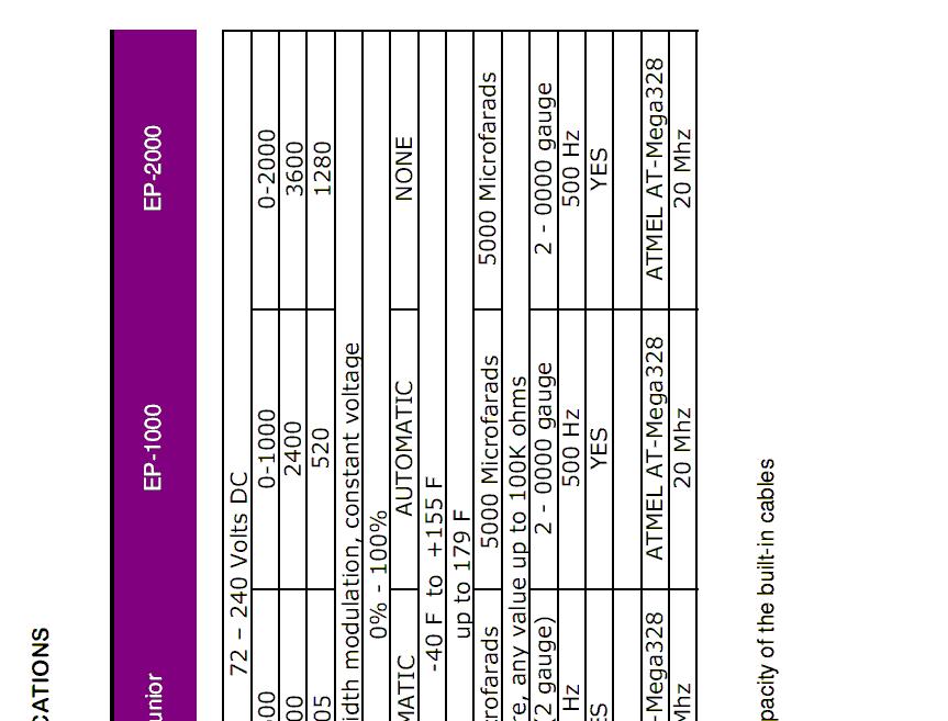
2 This manual covers the following EPC controllers: EP-2000 EP-1000 EP-Junior NEV Controller
3 INTRODUCTION The EP-Series of motor controllers are suitable for most industrial, automotive, and marine applications. They are designed to drive most brushed DC motors, including series-wound, separately excited, and permanent magnet motors. Separately Excited motors may require additional hardware, based on the application. All EP-Series controllers come configured to run off any DC power source, and can also be run from single-phase and three-phase AC power sources with our optional AC Module. All EPC controllers are designed to operate in harsh industrial environments. Installation is residential environments will require that the high voltage terminals of the unit to be shielded with a UL-Listed terminal protector or cover. All EPC Products are Manufactured in the United States of America
4 FEATURES True plug-and-play design... simply connect and go! Half the cost of a conventional industrial/automotive controller Soft-start technology allows for smoother acceleration 100% Waterproof and wet-location compliant No programming required Fanless, air-cooled design allows for a very small footprint Full optical isolation between high voltage and 12-volt systems Efficient heatsink and IGBT modules eliminate the need for liquid cooling Wide input voltage range: 24 to 320 volts Non-metallic enclosure increases safety and prevents corrosion All stainless steel / brass hardware included Energy-saving design operates at over 97% efficiency Brake pedal input for additional safety in the event of throttle bind / failure Built-in contactor delay allows you to turn on the contactors and controller at the same time, without the possibility of damaging components All EPC controllers will automatically detect your motor type, battery pack voltage, and potentiometer range. Programming is not necessary, except in rare cases where the equipment is being operated outside its normal range. In those cases, the processor will have to be replaced as outlined in the next few sections. All EPC controllers use a standard 6-pin wiring harness. This makes it easy to swap or upgrade the controller, without the need to re-wire the controller.
5 INSTALLATION INSTRUCTIONS A typical installation is shown below. If using an AC power source, a DC converter module must be placed where the battery is located. Controller can be installed in any orientation. A fan may be placed at or near the heatsink for additional cooling, in situations where the controller is operating at maximum or near maximum capacity most of the time.
6 SPECIAL NOTICE Always verify that NO HIGH VOLTAGE POTENTIAL is present on the 12 volt battery/power supply terminals. This can be dangerous to anyone servicing or using the equipment. Testing for this condition can be done as follows: Connect a high voltage meter between each 12 volt battery terminal (or power supply) and each high voltage battery terminal. The meter should read close to zero volts in all cases. For automotive applications, also check the voltage potential between the chassis/frame of the vehicle and each high voltage battery terminal. The meter should read close to zero volts in all cases. If there is a high voltage leak anywhere in the system, it must be repaired immediately. All EPC controllers are fully isolated, and cannot leak voltage into the 12-volt system.
 Connect to the NEGATIVE (-) of your 12 VOLT power supply or battery.")
7 LOW POWER TERMINAL CONNECTION All low power connections are pre-wired into a 6-pin wiring harness (see Figure 1) for easy installation. All EPC controllers use the same harness connector, and are interchangeable. Pin #1 (White Wire) Connect to the NEGATIVE (-) of your 12 VOLT power supply or battery. Pin #2 (Red Wire) Connect to the POSITIVE (+) of your 12 VOLT power source. This terminal is used to turn your controller ON. For electric vehicles, this is typically connected to the ignition switch. Pin #3 (Blue Wire) Brake Pedal Switch. Accepts +12V DC input to let the controller know that the brake pedal is depressed. This instructs the processor to go down to 0% throttle, regardless of the position of the potentiometer. If your motor is set to run continuously at idle, activating this wire will shut it down until the brake pedal is released. Although this connection is optional, we strongly recommend using it for automotive (EV and hybrid) applications. Pin #4, 5, 6 (Green, Brown, and Yellow Wires) Connect to your 3-wire potentiometer. Most standard 0-5k though 0-100k potentiometers can be used. M = Male Pins F = Female Pins Figure 1: Controller End Wiring Harness
 may also be used, but wires number 6 and 4 must be reversed.")
8 POTENTIOMETER CONNECTION The EP-1000 will auto-detect any standard a 3-wire potentiometer. Any value from 0-5k to 0-100k can be used. Reverse potentiometers (5-0k or 10-0k, for example) may also be used, but wires number 6 and 4 must be reversed. Most two-wire potentiometers (such as the Curtis PB-5 or PB-6) can also be used if you connect a wire from the third (unconnected) terminal of the potentiometer to the third terminal on the EP-1000 s throttle input (pin #6). To do this, you must first open the potentiometer s enclosure to gain access to the terminals and solder a wire to the unused potentiometer terminal. All EPC brand potentiometers are 3-wire, and come with a 6-pin EPC harness preinstalled. Due to their accuracy and high quality construction, we strongly recommend using only EPC potentiometer units with this controller. Low quality potentiometers can result in poor motor speed control, uneven throttle response, and often have a very short lifespan. Although an improperly connected potentiometer will not damage the controller itself, it could cause the controller to apply full power to the motor. This condition will cause the motor to operate at an unsafe speed, which could damage or even destroy the motor. Care should be taken not to power up the controller until proper installation of the potentiometer is verified. A diagnostic device (such as a duty cycle meter) can be used to show power output before connecting your motor. In some cases, a dummy load (such as a heater or light bulb) can be used in place of the motor, as long as the device is rated for the line voltage that you are using. Please call technical support at if you have difficulty with your potentiometer connections.
9 INTERNAL HARNESS CONNECTION NOTE: Wiring harness colors may change inside of the controller, however the pin order is always the same. Replacement wiring harnesses assemblies are available directly from EPC.
10 MAIN SYSTEM BOARD Figure 5 Main system board. Minor components removed for clarity. Please note that the IGBT Driver Modules are NOT replaceable. Because of the sophisticated hardware/software protection built into these modules, module failure is virtually impossible. In the unlikely event of a driver module failure, the module(s) must be professionally replaced. EPC does NOT recommend replacing these modules in the event of a failure. In such a case, the entire motherboard assembly should be replaced. The motherboard is available as a complete replacement assembly from EPC Corporation. The NEV Controller, EP-Junior, and most EP-1000 controllers only contain ONE driver module. The EP-2000, and special versions of the EP-1000 (such as the high frequency version) use TWO driver modules.

, and is easily removable. When replacing the processor, BE SURE to install it with the notch (or dot) facing the same direction. These indicators are visible in the pictures below.")
11 PROCESSOR REPLACEMENT Under normal circumstances, the main processor should never have to be replaced unless a software update is required. The processor is pre-programmed from the factory, and designed to outlast the equipment it operates. Processor replacement is only required if: Processor Stops Functioning Internal Programming is Corrupt Equipment Requires a Software Update The processor is installed in a 28-pin socket (8-pin for the NEV controller), and is easily removable. When replacing the processor, BE SURE to install it with the notch (or dot) facing the same direction. These indicators are visible in the pictures below. AT-MEGA328 (most common) Processor, Found in most EPjr and EP-1000 Controllers AT-Tiny85 Processor, Found in NEV Controllers Software updates are available from EPC Corporation, if needed. More information on software updates is available online at


12 INTERNAL COMPONENT IDENTIFICATION EP-Junior Figure 6 EP-Junior Controller Internal components of the EPjr are visible in this photograph. EMI shields, cables, and minor components have been removed for clarity. Please note that the controller above is a training model for service technicians; Actual production components and locations may vary slightly. Please use the part numbers on the next two pages when servicing.
13 INTERNAL COMPONENT IDENTIFICATION (CONTINUED) Internal components for the EPjr are shown in Figure 6 of the previous page. Other than the main processor, the internal components of these controllers are NOT userserviceable. The following part numbers are provided for authorized service technicians only. The replaceable system processor is located on the Main System Board (electronics board). When replacing the processor, use caution not to damage the surrounding electronic components. REPLACEMENT PART NUMBERS EP-Junior (Prior to 2011) OEM PART # Description for Replacement (including limits) PowerEx CM600HA-24A IGBT Module 1200V / 600A PowerEx RM300HA-24S Freewheel Diode Module - 300V / 300A EPCOS B43991-A4208-Q1 Electrolytic Capacitor 2000uf / 400 to 450V TPC FSG Film Capacitor 100 to 200uf / 600 to 1200V Aerovox RBPS Snubber Capacitor to 0.33uf / 800 to 1200V EPC EPJR-MB Processor and Control Board for IGBT TDK PH-FF Power Supply +20V EPC EPJR-H2 Wiring Harness (includes bulkhead) EP-Junior ( ) OEM PART # Description for Replacement (including limits) PowerEx CM600E3U-NFH IGBT Module 600V / 600A EPCOS B43991-A4208-Q1 Electrolytic Capacitor 2000uf / 400 to 450V TPC FSG Film Capacitor 100 to 200uf / 600 to 1200V Aerovox RBPS Snubber Capacitor to 0.33uf / 800 to 1200V EPC EPJR-MB Processor and Control Board for IGBT PowerEx VLA IGBT Gate Driver (mounted on EPJR-MB) EPC EPJR-H2 Wiring Harness (includes bulkhead)
14 REPLACEMENT PART NUMBERS EP-1000 (Prior to 2010) MANUFACTURER PART # QTY DESCRIPTION PowerEx CM600HA-24A 2 IGBT Module PowerEx RM400HA-24S 1 Freewheel Diode Module EPCOS B43991-A4208-Q1 2 Electrolytic Capacitor TPC FSG Film Capacitor Aerovox RBPS-33 2 Snubber Capacitor TDK PH-FF 1 Power Supply EPC EP1-MB 1 Processor and Control Board EPC EPJR-H2 1 Wiring Harness (includes bulkhead and connector) EP-1000 ( ) MANUFACTURER PART # QTY DESCRIPTION PowerEx CM600E3U-NFH 2 IGBT Module EPCOS B43991-A4208-Q1 2 Electrolytic Capacitor TPC FSG Film Capacitor Aerovox RBPS-33 2 Snubber Capacitor EPC EP1-MB 1 Processor and Control Board PowerEx VLA IGBT Gate Driver (on EP1-MB) EPC EPJR-H2 1 Wiring Harness (includes bulkhead and connector) EP-1000 ( up) MANUFACTURER PART # QTY DESCRIPTION PowerEx CM1000DXL-24S 1 IGBT Module EPCOS B43991-A4208-Q1 2 Electrolytic Capacitor TPC FSG Film Capacitor Aerovox RBPS-33 2 Snubber Capacitor EPC EP1-MB 1 Processor and Control Board PowerEx VLA IGBT Gate Driver (on EP1-MB) EPC EPJR-H2 1 Wiring Harness (includes bulkhead and connector)

 will NOT function correctly")


15 CONTROLLER PROTECTION FUSE PROTECTION Please note that a standard AC fuse should NOT be used in a DC circuit. The fuse must be SPECIFICALLY labeled for DC applications. For most larger motor applications, a 600A fuse will be sufficient. Application-specific fuses can be ordered directly from EPC. Also note that standard 125-volt and 240-volt DC circuit breakers (such as the AirPax JLM-1-1RLS ) will NOT function correctly because of the high voltage present when the motor s windings are discharged during normal operation. If using a circuit breaker, it must have a DC break rating higher than 600 volts. NO YES NO CONTACTORS A pair of contactors, or some other type of high-speed mechanical disconnect should be installed near the power supply. This not only allows for easy servicing, but can protect the motor and controller in the event of a short or system failure. Contactors are REQUIRED for all electric vehicles running DC motors. Pictured is a Curtis SW-200 Contractor. Contactors should have a continuous rating of at least 200 amps, with a surge capacity of about 1000 for this controller. Magnetic blowouts are required.


16 WET LOCATIONS Although all EPC controllers are water resistant, care should be taken during installation to protect any exposed high voltage terminals. The standard NEMA enclosure used for all EPC controllers protects the internal components, and is completely sealed from the environment. EP-1000 / EP-2000 The EP-1000 may be briefly submersed while running. All external connections should be protected from the environment by installing optional protection boots, as shown here. These boots are available from directly from EPC and most other industrial component suppliers. EP-Junior / NEV Controller The EP-Junior and Neighborhood Electric Vehicle controllers come with pre-installed motor and battery cables for easy installation. The cables are installed using water-tight connections, as shown to the right. This allows the controller to operate while submersed, without the possibility of voltage leaking into the water.
17 HEATSINK DATA (EP-1000) Material: Extruded Aluminum Width: " Length: Fin Height: 1.000" Base:.300" C/W/3": approximately 0.90 Weight per Inch: 0.48 lbs
18 ENCLOSURE DATA

19 CONTROLLER NEV EP-Junior EP-100
EPC DC MOTOR SPEED CONTROL
 EPC DC MOTOR SPEED CONTROL OPERATION AND INSTRUCTION MANUAL THIS MANUAL IS PUBLISHED BY EPC CORPORATION AND IS TO BE DISTRIBUTED ONLY WITH NEW EPC CONTROLS AND EQUIPMENT NO OTHER DISTRIBUTION IS PERMITED
OPERATION AND INSTRUCTION MANUAL. EP Series. Battery Chargers and Power Supplies
 OPERATION AND INSTRUCTION MANUAL EP Series Battery Chargers and Power Supplies THIS MANUAL IS PUBLISHED BY EPC CORPORATION AND IS TO BE DISTRIBUTED WITH NEW DEVICES ONLY NO OTHER DISTRIBUTION IS PERMITED
Kelly HSR Series Motor Controller with Regen User s Manual V 3.3. Kelly HSR Opto-Isolated Series Motor Controller with Regen.
 Kelly HSR Opto-Isolated Series Motor Controller with Regen User s Manual HSR72601 HSR72801 HSR12401 HSR12601 HSR12901 HSR14301 HSR14501 HSR14701 Rev.3.3 Dec. 2011 Contents Chapter 1 Introduction... 2 1.1
Elite Power Solutions Automatic Battery Control (ABC) Operation Manual
 Operation Manual") Elite Power Solutions Automatic Battery Control (ABC) Operation Manual Elite Power Solutions 335 E Warner Rd. STE 3 Chandler, AZ 85225 www.elitepowersolutions.com ABC Operation Manual Page 1 Table of Contents
Elite Power Solutions Automatic Battery Control (ABC) Operation Manual Elite Power Solutions 335 E Warner Rd. STE 3 Chandler, AZ 85225 www.elitepowersolutions.com ABC Operation Manual Page 1 Table of Contents
BX88175 Installation Instructions ToadStop II Vacuum Brake System
 BX88175 Installation Instructions ToadStop II Vacuum Brake System Serial No. Customer supplied tools & supplies Utility knife, 12VDC tester, drill & bits: (1/8", 1/4", 5/8 ), ¼ socket drive bit, punch,
EasyStart 364 (ASY-364-X20-IP) Installation Instructions for the Coleman / Airxcel Air Conditioners
 Installation Instructions for the Coleman / Airxcel Air Conditioners") EasyStart 364 (ASY-364-X20-IP) Installation Instructions for the Coleman / Airxcel Air Conditioners using Installation Kit KIT-364-CM1 Contents Introduction... 2 Safety first... 2 Making a good crimp...
EasyStart 364 (ASY-364-X20-IP) Installation Instructions for the Coleman / Airxcel Air Conditioners using Installation Kit KIT-364-CM1 Contents Introduction... 2 Safety first... 2 Making a good crimp...
Kelly HPM High Power Full Bridge Permanent Magnet DC Motor Controller User s Manual
 Kelly HPM High Power Full Bridge Permanent Magnet DC Motor Controller User s Manual HPM72601 HPM72801 HPM12401 HPM12601 HPM12801 HPM14301 HPM14501 HPM14701 Rev.3.4 Dec. 2016 Contents Chapter1 Introduction...
ATOTH-G Series BLDC Motor Controller. User s Manual
 ATOTH-G Series BLDC Motor Controller User s Manual Contents Chapter One Summary...1 Chapter Two Main Features and Specifications.2 2.1 Basic Functions...2 2.2 Features... 5 2.3 Specifications...6 Chapter
Kelly KDC Series/PM Motor Controller User s Manual
 Kelly KDC Series/PM Motor Controller User s Manual KDC48600 KDC48601 KDC48602 KDC48603 KDC72600 KDC72601 KDC72602 KDC72603 KDC72800 KDC72801 KDC72802 KDC72803 KDC12602 KDC12603 Rev.3.3 May 2011 Contents
Kelly KDHA High Voltage Series/PM Motor Controller User s Manual
 Kelly KDHA High Voltage Series/PM Motor Controller User s Manual KDH07500A KDH07501A KDH07700A KDH07701A KDH09400A KDH09401A KDH09500A KDH09501A KDH12400A KDH12401A KDH12500A KDH12501A KDH14300A KDH14301A
Small Full Bridge Permanent Magnet Motor DC Controller User Manual
 Small Full Bridge Permanent Magnet Motor DC Controller User Manual SPM24051X SPM24101X SPM24121X SPM48051X SPM48101X SPM48121X SPM72051X SPM72101X SPM72121X SPM48151E SPM48181E SPM48221E SPM72151E SPM72181E
INDEX Section Page Number Remarks
 INDEX Section Page Number Remarks Synchronous Alternators 2 4 General Fault Finding Capacitors 5 6 Fault Finding & Testing Diodes,Varistors, EMC capacitors & Recifiers 7 10 Fault Finding & Testing Rotors
Idle Timer Controller - ITC515-A Ford Transit Contact InterMotive for additional vehicle applications
 An ISO 9001:2008 Registered Company Idle Timer Controller - ITC515-A 2015-2018 Ford Transit Contact InterMotive for additional vehicle applications Overview The ITC515-A system will shut off gas or diesel
AFM500X Automatic Flashing Module
 AFM500X Automatic Flashing Module The Power-Tronics AFM500X Automatic Flashing Module is a convenient and compact optional build up module for all Power-Tronics UVR and XR series Universal Voltage Regulators.
CONTROL FEATURES AVAILABLE OPTIONS
 Vari Speed A2000 TABLE OF CONTENTS Control Features Options Application Data Operating Condition s Control Ratings Chart Mounting Dimensions Installation and Wiring Typical Wiring Diagram Schematic (Block
Filtered PWM Speed Control for Permanent Magnet DC Motors
 Instructions for Installation and Operation Filtered PWM Speed Control for Permanent Magnet DC Motors Model 0794 Speed and Direction Control up to 5/8 HP NEMA-1/IP-20 Specifications Product Type:... WPM-2148E1
Idle Timer Controller - A-ITC520-A Ford E Series Ford F250 - F Ford F250 - F550 (*B-ITC520-A) F650/F750
 F650/F750") An ISO 9001:2008 Registered Company Idle Timer Controller - A-ITC520-A 2009-2018 Ford E Series 2008-2016 Ford F250 - F550 2017-2018 Ford F250 - F550 (*B-ITC520-A) 2016-2018 F650/F750 *Uses the Ford 24-Pin
An ISO 9001:2008 Registered Company Idle Timer Controller - A-ITC520-A 2009-2018 Ford E Series 2008-2016 Ford F250 - F550 2017-2018 Ford F250 - F550 (*B-ITC520-A) 2016-2018 F650/F750 *Uses the Ford 24-Pin
Full Bridge Permanent Magnet DC Motor Controller User's Manual
 www.igreatway.com Email:info@igreatway.com V 3.3 Full Bridge Permanent Magnet DC Motor Controller User's Manual PM24101 PM24201 PM24301 PM36101 PM36201 PM48101 PM48201 PM48301 PM48401B PM48501B PM72101
ECO-6 & Installation Manual
 ECO-6 & Installation Manual For the SPA4-RFR Upgrade Kit To upgrade SPA4 amplifiers v1.00 & v1.01 to v2.0 Some sections also apply to the PA1, PA2, and PA3 14 August 2015 2015 by Ralph Hartwell Spectrotek
SHORT-STOP. Electronic Motor Brake Type G. Instructions and Setup Manual
 Electronic Motor Brake Type G Instructions and Setup Manual Table of Contents Table of Contents Electronic Motor Brake Type G... 1 1. INTRODUCTION... 2 2. DESCRIPTION AND APPLICATIONS... 2 3. SAFETY NOTES...
INSTALLATION INSTRUCTIONS
 1551 S. Vineyard Avenue Ontario, CA 91761 (909) 923-1973 INSTALLATION INSTRUCTIONS E-Z-GO Installation Notes CURTIS 1234, 1236 OR 1238 AC INDUCTION MOTOR/ CONTROLLER EZ-GO Curtis Controller Installation
CONSTANT PRESSURE CONTROLLERS
 CONSTANT PRESSURE CONTROLLERS SUBDRIVE AND MONODRIVE Franklin Electric s SubDrive and MonoDrive constant pressure controllers provide constant pressure by continually adjusting the speed of the pump to
EMERGENCY VEHICLE BATTERY MANAGER PS2024
 EMERGENCY VEHICLE BATTERY MANAGER PS2024 2 The PS2024 (Fig. 1) is designed as a on-vehicle battery charger / battery charge state monitor. While the vehicle is at its base or station, the charger is connected
Digitrip Retrofit System for ITE K-3000, K-3000 S, K-4000 and K-4000 S Breakers
 Supersedes IL 33-858-4 Dated 05/02 Digitrip Retrofit System for ITE K-3000, K-3000 S, K-4000 and K-4000 S Breakers Digitrip Retrofit System for ITE K-3000, Digitrip Retrofit System for ITE K-3000, K-3000
STARTING SYSTEMS 8B - 1 STARTING SYSTEMS CONTENTS
 TJ STARTING SYSTEMS 8B - 1 STARTING SYSTEMS CONTENTS page DESCRIPTION AND OPERATION STARTER MOTOR... 2 STARTER RELAY... 3 STARTING SYSTEM... 1 DIAGNOSIS AND TESTING STARTER MOTOR... 8 STARTER MOTOR NOISE
Idle Timer Controller - A-ITC620-A Chevrolet Express/GMC Savana
 Introduction An ISO 9001:2015 Registered Company Idle Timer Controller - A-ITC620-A1 2009-2019 Chevrolet Express/GMC Savana Contact InterMotive for additional vehicle applications The A-ITC620-A1 is an
T u n i n g. Professional Install
 DDM INSTALL GUIDE H1 HID Low Beams (35W or 55W) ddm T u n i n g TOOLS NEEDED: - Standard or metric socket set. Depending on the vehicle. - A drill and either a uni-bit or a 7/8 drill bit. - A Dremel with
ARM V FDBK ENSURE MOTOR IS NOT ROTATING DURING POWER UP STILL FAULTS? YES ENSURE ARMATURE WIRING IS ISOLATED FROM ANY OTHER POWER LEADS STILL FAULTS?
 ARM V FDBK ENSURE MOTOR IS T ROTATING DURING POWER UP This fault can only happen in the first 3 seconds after power up. The processor looks at the armature voltage. The voltage needs to be near 0. Possible
Brushed. Brushed. Brushed Motor
 Kelly Kelly Kelly Kelly KD KD KD KD Series Series Series Series DC DC DC DC Motor Motor Motor Motor Controller Controller Controller Controller User User User User s Manual Manual Manual Manual V 2.5 2.5
Idle Timer Controller - A-ITC620-A Chevrolet Express/GMC Savana
 An ISO 9001:2008 Registered Company Idle Timer Controller - A-ITC620-A1 2009-2018 Chevrolet Express/GMC Savana Contact InterMotive for additional vehicle applications Introduction The A-ITC620-A1 is an
Xebra Electrical Component Locations
 Xebra Electrical Component Locations Last updated on April 12, 2007 Copyright 2007. This document my not be reprinted, published, emailed or posted on the Internet without the approval of ZAP. Component
Devices Supported: KEB48220 KEB48221 KEB48300 KEB48301 KEB48400 KEB48401 KEB48600 KEB48601 KEB72330 EB KEB72450 KEB EB KEB72600 KEB
 Kelly KEB Brushless Motor Controller User s Manual Devices Supported: KEB48220 KEB48221 KEB48300 KEB48301 KEB48400 KEB48401 KEB48600 KEB48601 KEB72330 KEB EB72 72331 KEB72450 KEB EB72 72451 KEB72600 KEB
Click Here for Printable PDF File
 HWH Online Technical School Lesson 13: Hydraulic Leveling System Identification and Operation PART 2 Computer-Control (Automatic) Leveling Systems The 400 Series 610 Central Ground Series (400 / 500 /
ROADMASTER, Inc NE 127th Ave. Vancouver, WA Fax roadmasterinc.com ROADMASTER, Inc.
 ROADMASTER, Inc. 6110 NE 127th Ave. Vancouver, WA 98682 800-669-9690 Fax 360-735-9300 roadmasterinc.com 2008-2017 ROADMASTER, Inc. All rights reserved. 853600-05 11/17 Read all instructions before installing
VoltPro VP4 Automatic Voltage Regulator
 VoltPro VP4 Automatic Voltage Regulator The VoltPro VP4 Automatic Voltage Regulator is an affordable generator voltage regulator that is designed for the consumer market and can replace many popular voltage
Installation, Operation & Maintenance Manual
 Installation, Operation & Maintenance Manual Picture may differ from your specific application For Pro-Fill kits with part numbers beginning in BG BL-175 9-20-13 General Information & Precautions This
INSTALLATION MANUAL DIS4-009 DISTRIBUTORLESS IGNITION SYSTEM FOR ALL A/C VWs USING BOSCH 009 DISTRIBUTOR
 INSTALLATION MANUAL DIS4-009 DISTRIBUTORLESS IGNITION SYSTEM FOR ALL A/C VWs USING BOSCH 009 DISTRIBUTOR TABLE OF CONTENTS INTRODUCTION... 2 GENERAL COMMENTS... 3 REMOVE STOCK COMPONENTS... 3 FIGURES...
Mini Pump Installation, Operation & Maintenance Manual. For Models: BA-MS-633
 Mini Pump Installation, Operation & Maintenance Manual For Models: BA-MS-633 BL-309 6/08/2012 General Information & Precautions This publication provides detailed instructions for installing the single
Installation Instructions
 patent pending Portable Proportional Braking System Installation Instructions Part number 9400 Towing and Suspension Solutions ROADMASTER, Inc. 6110 NE 127th Ave. Vancouver, WA 98682 800-669-9690 Fax 360-735-9300
Installation, Operation & Maintenance Manual. For Pro-Fill kits with part numbers beginning in BG
 Installation, Operation & Maintenance Manual For Pro-Fill kits with part numbers beginning in BG BL-175 6/26/2009 General Information & Precautions This publication provides detailed instructions for installing
CAUTION: READ INSTRUCTIONS CAREFULLY BEFORE STARTING INSTALLATION
 V-Twin MFG. VT No. 32-9500 V-TECH 1 IGNITION KIT, SINGLE FIRE FITS EV SHOVEL, XL THRU 1997 VT No. 32-9503 V-TECH 1 IGNITION KIT, SINGLE FIRE FITS EV, SHOVEL, XL, WITH COIL AND WIRES This is a custom application
VECTRIX VX-2 SERVICE MANUAL. Version 1.0/May 2011 VECTRIX, LLC
 www.vectrix.com CONTENTS SECTION A: Tools 1 Tools Needed SECTION B: Mechanical Parts 1 Front Fairing 2 Front Console Cover 3 Speedometer Cover 4 Front Vertical Panel Cover-Lower 5 Front Vertical Panel
Installation and Construction Notes for EVSE4
 Installation and Construction Notes for EVSE4 You need to read and understand this if you want to build an EVSE that will be safe and need to pass a building inspectors review. Before beginning this process
Installation Instructions. PowerFlex 700 Drive - Frame 8 Components Replacement
 Installation Instructions PowerFlex 700 Drive - Frame 8 Components Replacement Important User Information Solid-state equipment has operational characteristics differing from those of electromechanical
Hydraulic Oil Cooler. Assembly Instructions (Originating w/serial Number )
") Hydraulic Oil Cooler Case 465 Skid Steer Assembly Instructions (Originating w/serial Number 50-101) Model Number: Serial Number: Date of Purchase: Specialized Equipment, Inc. 650 So. Main Street - PO Box
Hydraulic Oil Cooler Case 465 Skid Steer Assembly Instructions (Originating w/serial Number 50-101) Model Number: Serial Number: Date of Purchase: Specialized Equipment, Inc. 650 So. Main Street - PO Box
DC3N Non-Regenerative DC Drives
 PRICING 1/8-1.0 HP @ 115 VAC, 1-Ph, 50/60 Hz: 90 VDC Armature 1/4-2.0 HP @ 230 VAC, 1-Ph, 50/60 Hz: 180 VDC Armature For the Operation of Permanent Magnet DC Motors Only Product Features: DC3N Plate Model
A/C COMPRESSOR CLUTCH
 BR/BE CONTROLS 24-13 A/C COMPRESSOR CLUTCH DESCRIPTION The compressor clutch assembly consists of a stationary electromagnetic coil, a hub bearing and pulley assembly, and a clutch plate (Fig. 4). The
Pyrolance, LLC SPECIFICATIONS FOR DIESEL ENGINE DRIVEN ULTRA HIGH PRESSURE FIRE FIGHTING SYSTEM B2000 M-D
 SPECIFICATIONS FOR DIESEL ENGINE DRIVEN ULTRA HIGH PRESSURE FIRE FIGHTING SYSTEM B2000 M-D 1 HIGH PRESSURE FIRE FIGHTING SPECIFICATIONS Scope and General Design Requirements A fire fighting system shall
Product Guide: Series III Pump Control Board Set (RoHS)
") revised 04/08/10 Description: The Series III Pump Control Board Set provides motor drive and pump control for a wide assortment of pumps from Scientific Systems, Inc. The assembly consists of two circuit
revised 04/08/10 Description: The Series III Pump Control Board Set provides motor drive and pump control for a wide assortment of pumps from Scientific Systems, Inc. The assembly consists of two circuit
500 Series Troubleshooting Guide for C520 Alternators
 500 Series Troubleshooting Guide for C520 Alternators Hazard Definitions These terms are used to bring attention to presence of hazards of various risk levels or to important information concerning product
N1387 Series Troubleshooting Guide for N Alternators
 N1387 Series Troubleshooting Guide for N1387-1 Alternators Hazard Definitions These terms are used to bring attention to presence of hazards of various risk levels or to important information concerning
Grid Heater Starting Aid (T000)
") Page 1 of 14 Topic No. Rev. Level Topic Date Group No. 94T13-2 01-May-1994 13 Expiration Date (U.S. and Canada): Expiration Date (International): Engine Family 6B, ISB, QSB5.9, B5.9 Fuel System Plant From
Page 1 of 14 Topic No. Rev. Level Topic Date Group No. 94T13-2 01-May-1994 13 Expiration Date (U.S. and Canada): Expiration Date (International): Engine Family 6B, ISB, QSB5.9, B5.9 Fuel System Plant From
Battery Power Inverters
 Battery Power Inverters Renogy 500W 1000W 2000W Pure Sine Wave Inverter Manual 2775 E. Philadelphia St., Ontario, CA 91761 1-800-330-8678 1 Version 1.4 Important Safety Instructions Please save these instructions.
Owner s Manual. PowerVerterDC-to-AC Inverter
 Owner s Manual PowerVerterDC-to-AC Inverter Model: PV700HF Input V DC Output 0V, 60Hz AC Reliable AC Power Wherever You Need It Congratulations! You've purchased a high-quality Inverter designed to function
SM361 RIG SWITCH CONSTRUCTION MANUAL
 SM361 RIG SWITCH CONSTRUCTION MANUAL Document ver 1, For software release ver 1.1 May 27, 2016 Controls the power of 12V equipment while a vehicle is in use Product Development by: SM361 RIG SWITCH OVERVIEW
MOTORTRONICS Solid State AC Motor Control
 Solid State AC Motor Control MWH Series Solid State Motor Winding Heater 10 to 80 Amps INSTALLATION & START-UP MANUAL REV 4 6091101MN Table of Contents Chapter 1: General Information... 1 1.1 Introduction
Intelligent Lift Interlock System Installation Instructions
 Intelligent Lift Interlock System Installation Instructions MB 45/55 & International 3200 w/allison 2200/2400 Transmission & Shift Lock Solenoid Allison Generation 3 Controls Part # ILIS801-D 2002-2006
CTB-16K Hobbyist Line Kit 40 Amp 16 Channel Light Controller Assembly Manual *** Preliminary ***
 CTB-16K Hobbyist Line Kit 40 Amp 16 Channel Light Controller Assembly Manual *** Preliminary *** Version 1.0 January 12, 2006 Copyright Light O Rama, Inc. 2006 Table of Contents 1 Introduction... 3 2 Required
Application Engineering
 Application Engineering February, 2009 Copeland Digital Compressor Controller Introduction The Digital Compressor Controller is the electronics interface between the Copeland Scroll Digital Compressor
RECOMMENDED TOOLS PERSONAL & VEHICLE PROTECTION SAFETY GLASSES
 2014 FORD TRANSIT FULL SIZE PART NUMBER: 250-9636 GENERAL APPLICABILITY THIS CRUISE WAS TESTED AND VERIFIED ON: FORD TRANSIT 150, 250 RECOMMENDED TOOLS PERSONAL & VEHICLE PROTECTION SAFETY GLASSES KIT
Gas Spreader PLUS Remote Kit With Built in Clutch Relay and On/Off Switch
 Gas Spreader PLUS Remote Kit With Built in Clutch Relay and On/Off Switch NOTE: Read all directions first before continuing. This wireless controller kit has been programmed and tested before shipping.
WARNING TABLE 3-1: DAILY SAFETY CHECK
 III. T PSL-10 MAINTENANCE his chapter contains maintenance information for the Ricon PSL-10. The information consists of a maintenance schedule, component descriptions, electrical diagrams, fuse locations,
English - Español - Français - Deutsch - Italiano
 English - Español - Français - Deutsch - Italiano INTRODUCTION Thank you for purchasing Power Probe products. The Power Probe is the best professional electrical tester for reducing diagnostic time in
D&D Motor Systems, Inc.
 D&D Motor Systems, Inc. Programmable Regen Controller Manual & Schematics BE ADVISED, D&D Motor Systems, Inc. does not design and manufacture controllers. We provide them as an extension to our existing
INSTALLATION MANUAL AP60B INSTALLATION MANUAL
 INSTALLATION MANUAL 2. TOOLS REQUIRED The following is a list of tools required to properly install the cruise control. While this unit may be installed without some of the tools listed, it is recommended
IDC-136II-KIT 136kHz DC RX Assembly Guide
 IDC-136II-KIT 136kHz DC RX Assembly Guide ICAS Enterprises May 2 nd,2016 The IDC-136II-KIT is a 136kHz direct conversion receiver. Most of the SDR software can be used with this receiver. It is quite easy
2015 EDITION SUBMERSIBLE MOTORS AIM MANUAL. APPLICATION INSTALLATION MAINTENANCE 60 Hz, Single-Phase and Three-Phase Motors. franklinwater.
 0 EDITION AIM MANUAL SUBMERSIBLE MORS APPLICATION INSTALLATION 60 Hz, Single-Phase and Three-Phase Motors franklinwater.com All Motors System Troubleshooting Motor Does Not Start A. No power or incorrect
ACC Series Power Conditioner OPERATION & INSTALLATION MANUAL
 ACC Series Power Conditioner OPERATION & INSTALLATION MANUAL PHASETEC digital power conditioners are designed to safely operate electrical equipment in the harshest power quality environments. With a wide
SPEED SHIFT/TWO-STEP MODULE INSTALLATION MANUAL
 SPEED SHIFT/TWO-STEP MODULE INSTALLATION MANUAL ALTHOUGH THIS PRODUCT HAS BEEN THOROUGHLY TESTED KPIERSON TECHNOLOGIES ASSUMES NO RESPONSIBILITY FOR ANY DAMAGE THAT MAY RESULT BY THE INSTALLATION OF THIS
WARRANTY INFORMATION...
 Table of contents 1 General Information... 3 1.1 Description... 3 1.2 Features... 3 1.3 Specifications... 4 1.4 Receiving and Unpacking... 4 1.5 Dimensions... 4 2 Installation... 5 2.1 Wiring... 5 3 Operation...
EasyStart Installation Instructions for Dometic Family RV A/Cs
 EasyStart Installation Instructions for Dometic Family RV A/Cs DuoTherm Brisk Brisk II Penguin Penguin II Contents Introduction... 4 Safety first... 4 Making a good crimp... 4 Identifying Dometic AC Units...
RECOMMENDED TOOLS PERSONAL & VEHICLE PROTECTION SAFETY GLASSES
 PART NUMBER: 250-9625 GENERAL APPLICABILITY THIS CRUISE WAS TESTED AND VERIFIED ON: ALL MODELS RECOMMENDED TOOLS PERSONAL & VEHICLE PROTECTION SAFETY GLASSES KIT CONTENTS/SERVICE PARTS ITEM QTY DESCRIPTION
Engine Performance Troubleshooting Tree - Signature and ISX CM870
 File: 70-t02-1001 Page 1 of 64 Engine Performance Troubleshooting Tree - Signature and ISX CM870 This troubleshooting procedure should be followed for the following symptoms: Engine Acceleration or Response
INSTRUCTIONS INSTALLATION OF LOAD-SHARE TERMINALS FOR VLT DRIVES
 INSTRUCTIONS INSTALLATION OF LOAD-SHARE TERMINALS FOR VLT DRIVES This instruction sheet is for the field installation of load-share terminals for the VLT series drives frames D1, D2, D3 and D4. Kit Contents
Advanced EasyStart Troubleshooting
 Advanced EasyStart Troubleshooting EasyStart is designed for excellent reliability and durability. Every EasyStart is tested on a compressor before it leaves Micro-Air to ensure it will work when delivered.
Yaskawa Electric America Unit Troubleshooting Manual Section One: Introduction & Checks Without Power GPD 506/P5 and GPD 515/G5 (0.
 Yaskawa Electric America Unit Troubleshooting Manual Section One: Introduction & Checks Without Power GPD 506/P5 and GPD 515/G5 (0.4 ~ 160kW) Page 1 Introduction This manual is divided into three sections:
TROUBLESHOOTING GUIDE FOR HEAT PUMP BOOSTERS MODELS: HPB11, HPB15, & HPB22
 V3 TROUBLESHOOTING GUIDE FOR HEAT PUMP BOOSTERS MODELS: HPB11, HPB15, & HPB22 PREFACE This guide contains instructions for troubleshooting the Steffes Corporation room heating units: Models HPB 11, HPB
C802/C802D/C802TD/C820 Alternators Troubleshooting Guide
 C802/C802D/C802TD/C820 Alternators Troubleshooting Guide Hazard Definitions These terms are used to bring attention to presence of hazards of various risk levels or to important information concerning
OPERATION AND MAINTENANCE
 Table of Contents GENERAL INFORMATION INTRODUCTION... 1 Operating Specifications... 1 FEATURES... 1 SAFETY PRECAUTIONS... 2 SET-UP... 2 OPERATION AND MAINTENANCE TESTING AN IGNITION MODULE OR IGNITION
ST Charger. Industrial Battery Charger
 ST Charger Industrial Battery Charger Installation and Operation Manual ST_13 Table of Contents Pg# 1.0 INSTALLATION 1 1.1 Receiving 1 1.2 Location 1 1.3 Line Voltage 1 1.4 A.C. Service Requirements 2
FiveFish Studios PSU-2448Plus+ Assembly Guide
 FiveFish Studios PSU-2448Plus+ Assembly Guide Copyright 2015-2017 FiveFish Audio Revision 1.02-20171105 No part of this document may be reproduced, either mechanically or electronically, posted online
INSTALLATION & OWNER S MANUAL
 1 of 18 INSTALLATION & OWNER S MANUAL (*Not including cab & other accessories) A/C Alternator Kit: Yamaha Drive & Drive2 P/N: 1ACYDR2DRK Recommended it be installed with Curtis Cab: Sandstone (p/n 1GCYD1-A,
User's Manual O
 11/3/99 3535.ai User's Manual 3535 3535 O Step Motor Drivers Copyright 1998 Applied Motion Products, Inc. 404 Westridge Drive Watsonville, CA 95076 Tel (831) 761-6555 (800) 525-1609 Fax (831) 761-6544
C.E. Niehoff & Co. N1601, N1602, N1603, and N1604 Alternator Troubleshooting Guide NOTICE. Hazard Definitions. Battery Charge Volt and Amp Values
 C.E. Niehoff & Co. N1601, N1602, N1603, and N1604 Alternator Troubleshooting Guide Hazard Definitions These terms are used to bring attention to presence of hazard(s) of various risk levels or to important
Stay-IN-Play with Panic Stop Braking
 INSTALLATION INSTRUCTIONS TOWED VEHICLE BRAKING SYSTEM Stay-IN-Play with Panic Stop Braking SMI Manufacturing, Inc. P.O. Box 14040 Evansville, IN 47728 1-800-893-3763 www.smibrake.com SIP0906 Model SIP0603
RANGER 900 POWER STEERING KIT
 RANGER 900 POWER STEERING KIT P/N 2880083 APPLICATION MY14 AND NEWER RANGER XP 900 MODELS IMPORTANT It is strongly recommended that this kit be installed by an authorized Polaris dealer. NOTE Use of this
SUPER CAPACITOR CHARGE CONTROLLER KIT
 TEACHING RESOURCES ABOUT THE CIRCUIT COMPONENT FACTSHEETS HOW TO SOLDER GUIDE POWER YOUR PROJECT WITH THIS SUPER CAPACITOR CHARGE CONTROLLER KIT Version 2.0 Teaching Resources Index of Sheets TEACHING
WOT Box Installation Instructions VW / Audi
 Connector Pinout Pin Color AWG Name WOT Box Installation Instructions VW / Audi Description 1 Yellow 18 RPM Connect to Fuel Injector Drive Signal or Ignition Control Signal (varies by car model) 2 Black
CONSTANT PRESSURE CONTROLLERS
 CONSTANT PRESSURE CONTROLLERS SUBDRIVE AND MONODRIVE Franklin Electric s SubDrive and MonoDrive constant pressure controllers provide constant pressure by continually adjusting the speed of the pump to
C FORD F250 / F L POWERSTROKE DIESEL WITH AUTOMATIC TRANSMISSIONS ONLY
 EXHAUST BRAKES C40019 1999-2003 FORD F250 / F350 7.3L POWERSTROKE DIESEL WITH AUTOMATIC TRANSMISSIONS ONLY Getting Started Thank you and congratulations on your purchase of a Pacbrake exhaust retarder.
RECOMMENDED TOOLS PERSONAL & VEHICLE PROTECTION SAFETY GLASSES
 HYUNDAI ACCENT 2010- /ELANTRA 2012- / KIA RIO 2012- PART NUMBER: 250-9628-NS GENERAL APPLICABILITY THIS CRUISE WAS TESTED AND VERIFIED ON: (AT/MT) VEHICLES RECOMMENDED TOOLS PERSONAL & VEHICLE PROTECTION
GS10 Series MODELS: GS10 GS10-R NEMA 4X SCR MOTOR CONTROLS. User s Manual
 GS10 Series MODELS: GS10 GS10-R NEMA 4X SCR MOTOR CONTROLS User s Manual Safety Warnings SHOCK HAZARD AVOID HEAT KEEP DRY AVOID VIBRATION This symbol denotes an important safety tip or warning. Please
PLEASE READ BEFORE CALLING OR RETURNING PRODUCT. EXTREMELY IMPORTANT!!!
 Thank you for your purchase of WeaponX Smart Direct Fire Ignition Coil System for your vehicle. The following are the instruction manuals for your ignition system kit. Please read carefully and enjoy your
Eminox Electronic Service Indicator
 ESI Installation and Instruction Manual Eminox Electronic Service Indicator I n s t a l l a t i o n a n d I n s t r u c t i o n M a n u a l LITM004 ESI Installation and Instruction Manual Section Title
MB A 12V/24V DC PROGRAMMABLE DUAL BATTERY ISOLATOR
 MB-3688 120A 12V/24V DC PROGRAMMABLE DUAL BATTERY ISOLATOR User Manual Warning and Precautions MB-3688 is built with corrosion resistant material and the main electronic assembly is well sealed inside
CRUISE CONTROL SYSTEM
 CRUISE CONTROL SYSTEM 1993 Mitsubishi Montero 1993 ACCESSORIES & EQUIPMENT Mitsubishi Cruise Control Systems Montero DESCRIPTION & OPERATION The cruise control system is electronically and vacuum controlled.
AC Rectifiers for use with Armature Actuated Brakes. Product Overview. Full Wave. Half Wave. Combination Full and Half Wave. TOR-AC Full and Half Wave
 Rectifiers for use with Armature Actuated Brakes Product Overview NOTE: For brake response times with and without rectifiers see page 94. Full Wave A rectifier in which both positive and negative half-cycles
GENESIS Electronic Brake Controller Hayes Brake Controller Company - P/N 81790
 GENESIS Electronic Brake Controller Hayes Brake Controller Company - P/N 81790 INSTALLATION MANUAL For trailers with 2-8 electric brakes and vehicles with 12 volt negative ground systems only. READ AND
CHARGING SYSTEM 8C - 1 CHARGING SYSTEM CONTENTS
 ZG CHARGING SYSTEM 8C - 1 CHARGING SYSTEM CONTENTS page GENERAL INFORMATION OVERVIEW... 1 DESCRIPTION AND OPERATION BATTERY TEMPERATURE SENSOR... 2 CHARGING SYSTEM OPERATION... 1 ELECTRONIC VOLTAGE REGULATOR...
EVO AT SERIES BATTERY CHARGER
 EVO AT SERIES BATTERY CHARGER AT SERIES BATTERY CHARGER P R O D U C T PATENT PENDING hindlepowerinc.com 610-330-9000 Evo AT Series battery charger designed with YOU in mind. Evo AT Series battery charger