INSTALLATION MANUAL DIS4-009 DISTRIBUTORLESS IGNITION SYSTEM FOR ALL A/C VWs USING BOSCH 009 DISTRIBUTOR
|
|
|
- Verity Marsh
- 6 years ago
- Views:
Transcription


1 INSTALLATION MANUAL DIS4-009 DISTRIBUTORLESS IGNITION SYSTEM FOR ALL A/C VWs USING BOSCH 009 DISTRIBUTOR
2 TABLE OF CONTENTS INTRODUCTION... 2 GENERAL COMMENTS... 3 REMOVE STOCK COMPONENTS... 3 FIGURES... 4 INSTALL COIL PACK... 6 INSTALL COMPU-TRONIX DISTRIBUTOR... 6 SETTING INITIAL TIMING... 7 INSTALL SPARK PLUG WIRES... 7 FINAL ELECTRICAL CONNECTIONS... 8 SETTING FINAL IGNITION TIMING... 8 TROUBLESHOOTING... 9 CONTACT COMPU-TRONIX... 9 INTRODUCTION Congratulations! You have just purchased the highest performance ignition system available for a VW engine equipped with a Bosch 009 Distributor. READ THESE INSTRUCTIONS COMPLETELY BEFORE BEGINNING INSTALLATION! If you are in doubt about any of the procedures, have a qualified automotive technician install the system for you! Refer to the diagram sheet (pages 5 and 6) during installation. Use photographs in this manual for reference only. VERIFY THE CONTENTS OF THE SYSTEM. It should contain the following: DIS4-009 Electronic Distributor 4 Tower Ignition Coil Pack Coil Pack Mounting Plate 8 mm Spark Plug Wire Set Hardware Kit (2) M6x14 Phillips, Flat Head Screws (3) M6x25 Socket Head Screws (6) M6 Flat Washers (3) M6 Lock Washers (4) Screw-on Spark Plug Adaptors 2
3 GENERAL COMMENTS These instruction sheets are precise and accurate. They are designed to take you through the installation, step by step, in a logical sequence. If you follow them, the system will work the first time, every time. If you do not follow them, Cypress Engineering cannot guarantee the results. Due to the high-energy output of this system, only silicone high voltage leads, such as the ones supplied with the system, can be used. High quality spark plugs, in new or good condition must be used. Recommended spark plug gap is Never crank the engine with any high voltage wires disconnected from the Coil Pack terminals or spark plugs. This puts a very high stress on the coil and it is dangerous! DO NOT try to time this system with a dial back timing light! Each spark plug wire conducts current once per engine revolution instead of once every other revolution as in a conventional system. This causes a dial back timing light to give a false reading! Use only a standard timing light with a clamp on inductive type pick up. REMOVE STOCK COMPONENTS 1. Remove high voltage wire from ignition coil. 2. Remove all of the high voltage wires from the spark plugs. 3. Remove the distributor cap and set it and the high voltage wires out of the way. 4. Remove the wire from the ignition coil primary negative (-) terminal that connects to the distributor. CAUTION: MAKE SURE THE IGNITION SWITCH IS OFF!! The wire from the ignition switch to the ignition coil primary terminal is NOT fused in many applications. If this wire is allowed to touch vehicle or engine ground, with the ignition switch on, it can cause a direct short on the battery possibly causing permanent damage to the vehicle wiring and a fire. Cypress Engineering assumes no liability for damage caused from this occurrence or due to any faults in the existing vehicle wiring. 5. Remove the ignition switch wire from the ignition coil primary positive (+) terminal. Make sure this wire does not come into contact with vehicle or engine ground. 6. Remove the ignition coil and mounting strap from the fan housing and set them aside. 3


4 FIGURES 4
5 5
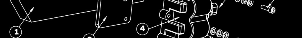
6 INSTALL COIL PACK 1. Refer to Figure 1. Attach the Coil Pack Mounting Bracket (2) to the fan housing (1) using the two M6x14 Phillips flat head screws (3) provided. These screws should be tightened securely. The use of a nonpermanent thread locking adhesive is recommended. 2. Attach the Coil Pack (4) to the Coil Pack Mounting Bracket (2) using the three M6x25 socket head screws (8), six M6 flat washers (6), and three M6 lock washers (7). Mount Bracket To Fan Housing And Mount Coil To Bracket IT IS ABSOLUTELY ESSENTIAL THAT YOU USE THE EXACT COMBINATION OF WASHERS AND LOCK WASHERS, THAT ARE PROVIDED, TO INSURE THAT THE SCREWS (8) ENGAGE THE MAXIMUM NUMBER OF THREADS IN THE MOUNTING PLATE WITHOUT HITTING THE FAN HOUSING (1)!! INSTALL COMPU-TRONIX DISTRIBUTOR 1. Loosen the screw in the distributor clamp, remove the distributor and set it aside. 2. Install the Compu-Tronix distributor. 3. Tighten the clamp just enough so that the distributor can still be turned by hand. 4. Refer to Figure 2. Insert the plug (15) on the wire harness (18) into the socket (16) on top of the Compu-Tronix distributor. The plug will only go into the socket one way. DO NOT connect the plug (23) on the other end of the wire harness, to the coil pack at this time. 5. Refer to Figure 4. With the ignition switch off, the gear shift in neutral and the emergency brake set, rotate the engine until the notch in the pulley is about ¾ to the left of the split in the crankcase. 6

 2. Turn the ignition switch ON.")


7 SETTING INITIAL TIMING 1. Connect the ignition switch wire (the one that was removed from the positive coil terminal) to the red wire (22), in the wire harness. (This wire has an insulated male spade terminal on it.) 2. Turn the ignition switch ON. 3. The LED static timing light (21), in the top of the Compu-Tronix Distributor, may be on or off. If it is off, slowly rotate the distributor counterclockwise until the LED just turns on. This is the point at which #1 cylinder will fire. If the LED is initially on, rotate the distributor clockwise until the LED turns off. The distributor may need to be rotated up to 120 for the LED to turn off. Then slowly rotate the distributor counterclockwise until the LED just turns back on. This is the point at which #1 cylinder will fire. TURN THE IGNITION SWITCH OFF. The timing is now set with about 10º initial advance. This will allow for the engine to be started so the timing can be set. 4. Tighten the distributor clamp. INSTALL SPARK PLUG WIRES NOTE: IF THE SPARK PLUGS HAVE THREADED ELECTRICAL CONTACTS, INSTALL THE INCLUDED SCREW ON TERMINALS. Refer to Figure 5. There are two long spark plug wires and two shorter ones in the spark plug wire set supplied. The two long wires go to cylinders #1 and #2. The two shorter wires go to cylinders #3 and #4. The cylinder designations in the VW Beetle are as follows: #1 Passenger side front #3 Driver side front #2 Passenger side rear #4 Driver side rear The cylinder designations, for the connection of the spark plug wires, of the Coil Pack are shown in Figure 5. IGNORE THE CYLINDER NUMBERS MOLDED INTO THE COIL PACK!! Install the spark plug wires to the spark plugs and coil pack. The best procedure is to install one wire completely from the spark plug to the coil pack. Then go onto the next wire. Make sure all wires are fully seated on the spark plugs and coil pack terminals. Route Coil Pack Wires As Needed Ensure Good Seal With Head Tin 7
8 FINAL ELECTRICAL CONNECTIONS MAKE SURE THE IGNTION SWITCH IS OFF! 1. Connect the wire harness plug (23 Figure 2) to the Coil Pack Connector (5 Figure 1). The connectors will only go one way and have a spring clip to hold them together. Push the spring wire, on connector (23), down to insert into or remove the connector (23) from the Coil Pack Connector (5). Make sure the connectors are fully mated and that the spring clip locks it in place when released. 2. Connect the ignition switch wire to the red wire (22 Figure 2), in the wire harness. Connect the wire from the tachometer (if applicable) to the purple wire (24) coming from the wire harness. If you are not using a tachometer, tape off the connector on the purple wire. The ignition switch and tachometer wires should be terminated with fully insulated ¼ female spade connectors. 3. Make sure none of the wiring or connectors are lying against any surface that gets hot enough to cause damage. SETTING FINAL IGNITION TIMING NOTE: A variable or dial back timing light can not be used unless the delay is set to ZERO and it is used as a conventional timing light! Start the engine. The engine is timed in the conventional manner using a conventional timing light with an inductive pick up clamp. The inductive pick up should be clamped around the #1 spark plug wire. If the timing light is weak, reverse the orientation of the inductive pick up on the spark plug wire. Ignition timing should be set at maximum advance. Typical timing is 33º to 35º BTDC at maximum advance. The engine should be running at 3,000 to 3,200 to check maximum advance. 8
9 TROUBLESHOOTING DO NOT ATTEMPT TO SEE IF THE SYSTEM IS FIRING BY DISCONNECTING A SPARK PLUG WIRE AND HOLDING IT NEXT TO GROUND. THE HIGH VOLTAGE CREATED BY THIS PROCEDURE STRESSES THE INSULATION AT THE COIL AND IS VERY DANGEROUS! Engine cranks but does not start No spark present Determine if the red LED light flashes on and off when the engine is cranked. If it does, the ignition switch wire connection is good and the system is triggering correctly. If the red LED stays off, the system is not getting 12 volts from the ignition switch wire. Verify that there is 12 volts present at the ignition switch wire when the ignition switch is turned on. Verify that the connectors are fully inserted and seated. Engine starts but backfires/misfires The spark plug wires may be connected incorrectly. Recheck that the spark plug wires are connected as shown in Figure 5. Make sure all rubber boots on the spark plug wires are fully seated at both the coil pack and spark plug ends. CONTACT COMPU-TRONIX Compu-Tronix Carrey Rd. Walnut, CA Phone: Fax: Tech Support: support@compu-tronix.com Sales: sales@compu-tronix.com Compu-Tronix is a division of Cypress Engineering. 9
CAUTION: READ INSTRUCTIONS CAREFULLY BEFORE STARTING INSTALLATION
 V-Twin MFG. VT No. 32-9500 V-TECH 1 IGNITION KIT, SINGLE FIRE FITS EV SHOVEL, XL THRU 1997 VT No. 32-9503 V-TECH 1 IGNITION KIT, SINGLE FIRE FITS EV, SHOVEL, XL, WITH COIL AND WIRES This is a custom application
Tri-Spark Ignition System Installation Triple Cylinder TRI-0001
 Tri-Spark Ignition System Installation Triple Cylinder TRI-0001 There are potentially lethal high voltages produced at the ignition coils and spark plugs, therefore every precaution must be taken to prevent
INSTALLATION INSTRUCTIONS for HI-4 DUAL FIRE MOTORCYCLE IGNITION. Part Number INTRODUCTION REMOVAL OF POINTS IGNITION TO 1977 MODELS
 INSTALLATION INSTRUCTIONS for HI- DUAL FIRE MOTORCYCLE IGNITION Part Number -00 CAUTION: READ INSTRUCTIONS CAREFULLY BEFORE STARTING INSTALLATION INTRODUCTION The HI- ignition system is intended for use
SPEED SHIFT/TWO-STEP MODULE INSTALLATION MANUAL
 SPEED SHIFT/TWO-STEP MODULE INSTALLATION MANUAL ALTHOUGH THIS PRODUCT HAS BEEN THOROUGHLY TESTED KPIERSON TECHNOLOGIES ASSUMES NO RESPONSIBILITY FOR ANY DAMAGE THAT MAY RESULT BY THE INSTALLATION OF THIS
1.5L L
 Selected Block IGNITION TIMING NOTE: Perform all adjustments with engine at normal operating temperature, cooling fan and accessories off, transmission in Park or Neutral, and front wheels in straight-ahead
INSTALLATION INSTRUCTIONS for HI-1 and HI-2 MOTORCYCLE IGNITIONS. Part Numbers and INTRODUCTION COIL AND SPARK PLUG CABLE CONSIDERATIONS
 INSTALLATION INSTRUCTIONS for HI- and HI- MOTORCYCLE S Part Numbers 8-000 and 8-000 CAUTION: READ INSTRUCTIONS CAREFULLY BEFORE STARTING INSTALLATION INTRODUCTION Crane HI- and HI- ignition systems are
DISTRIBUTORLESS IGNITION SYSTEM Installation and Adjustment Instructions
 DISTRIBUTORLESS IGNITION SYSTEM Installation and Adjustment Instructions 1.0 INTRODUCTION: Congratulations on your purchase of a Holley Distributorless Ignition System! Holley cannot and will not be responsible
12/30/2018 Fuel/Ignition Ignition Distributor Removal and Installation Distributors 1997 Dodge RAM Pickup (5.2L V8) - BR MotoLogic
 - BR MotoLogic") 1997 RAM Pickup (5.2L V8) - BR DISTRIBUTORS REMOVAL Report a problem with this article CAUTION: Base ignition timing is not adjustable on any engine. Distributors do not have built in centrifugal or vacuum
1997 RAM Pickup (5.2L V8) - BR DISTRIBUTORS REMOVAL Report a problem with this article CAUTION: Base ignition timing is not adjustable on any engine. Distributors do not have built in centrifugal or vacuum
STRIP ANNIHILATOR Ignition System Part Number
 STRIP ANNIHILATOR Ignition System Part Number 800-200 Installation Instructions and Troubleshooting Manual One or more of the following items may be required to complete the installation of this kit. 820-200
Viper 90R Dies After Shifting
 3/9/2005 Problem: Unit will not shift into gear or engine dies when shifting into gear. (1) i. Turn on the ignition switch. ii. Set selector switch to neutral (N) position. iii. Set stop switch to O position.
Technical Sheet on Sprint Tachometers and MSD Ignition Systems. How to Install a Sprint Tachometer With a MSD 6A Ignition System
 Technical Sheet on Sprint Tachometers and MSD Ignition Systems How to Install a Sprint Tachometer With a MSD 6A Ignition System Step 1: Wiring Procedures Sprint Tachometers are voltage-triggered tachometers
MSD Stacker-4 (4-Channel), PN 7010 Stacker-8 (8-Channel), PN 7020
, PN 7010 Stacker-8 (8-Channel), PN 7020") INSTALLATION INSTRUCTIONS 1 MSD Stacker-4 (4-Channel), PN 7010 Stacker-8 (8-Channel), PN 7020 Important: Read these instructions before attempting this installation! Parts Included: 1 - MSD Stacker Ignition
INSTALLATION INSTRUCTIONS 1 MSD Stacker-4 (4-Channel), PN 7010 Stacker-8 (8-Channel), PN 7020 Important: Read these instructions before attempting this installation! Parts Included: 1 - MSD Stacker Ignition
ULTRA TEAM TABLE OF CONTENTS I. INTRODUCTION
 JACOBS "i.c.e. PAK" -. (import Car Energy PAK) ULTRA TEAM INSTALLATION INSTRUCTIONS LEGAL FOR INSTALLATION IN ALL 50 STATES PER CARB EO #D-19-32 NOTE TO INSTALLER:' Before starting installation, read this
CAUTION: CAREFULLY READ INSTRUCTIONS BEFORE PROCEEDING
 Daytona Sensors LLC Engine Controls and Instrumentation Systems Installation Instructions for WEGO II Wide-Band Exhaust Gas Oxygen Sensor Interface Methanol Version CAUTION: CAREFULLY READ INSTRUCTIONS
Instruction Manual P/N B Series COP Conversion Kit
 Instruction Manual P/N 30-2860 B Series COP Conversion Kit KIT CONTENTS 1 x 35-2840 IGNITER W/ BRACKET 1 x 30-3255 HONDA EPM 4 x 30-2850 COIL 1 x 35-3860 B SERIES COP HARNESS 1 x 35-3861 EPM HARNESS 2
Distributorless Ignition System (DIS) Application: LLV Part Number: (E) or (A) Time Required: Approx.
 Application: LLV Part Number: (E) or (A) Time Required: Approx.") www.teamwbi.com / e-mail: mip@teamwbi.com / 800-842-7285 Distributorless Ignition System (DIS) Application: 1987 1993 LLV Part Number: 01-5332 (E) or 01-5333 (A) Time Required: Approx. 1 hour Quantity
www.teamwbi.com / e-mail: mip@teamwbi.com / 800-842-7285 Distributorless Ignition System (DIS) Application: 1987 1993 LLV Part Number: 01-5332 (E) or 01-5333 (A) Time Required: Approx. 1 hour Quantity
Signal Mirror Installation Instructions
 Signal Mirror Installation Instructions Ford F-250 to F-750 Pick-Up, Super-Duty 1998-2007 Trailer Tow Mirror Ford Excursion XLT/Limited 2000-2002 Trailer Tow Mirror Ford Excursion (all models) 2003-2005
Detroit Speed, Inc. Electric Headlight Door Kit Corvette P/N: &
 Detroit Speed, Inc. Electric Headlight Door Kit 1968-82 Corvette P/N: 122006 & 122007 The Detroit Speed Inc. Electric Headlight Door Kit replaces the stock vacuum actuated system on all 1968-82 Corvettes.
INSTRUCTIONS. 20 Circuit Wiring Kit Instructions October 2009, Speedway Motors, Inc.
 1 MAIN FUSE PANEL The main fuse panel harness s designed to be mounted under the dash a the firewall in an area close to the steering column. The enclosed representation of the main dash harness shows
PERFORMER-PLUS CAMSHAFT / LIFTERS / LUBE KIT CATALOG # 2103 MODEL: 400 c.i.d. Chevrolet V8 engines GENERAL INSTRUCTIONS
 PERFORMER-PLUS CAMSHAFT / LIFTERS / LUBE KIT CATALOG # 2103 MODEL: 400 c.i.d. Chevrolet V8 engines GENERAL INSTRUCTIONS Please study these instructions carefully before you remove your stock camshaft.
w.get2itparts.com Viper 90R-4 Dies After Shifting Or Indicator Lights Blink SCL /24/2005
 10/24/2005 Viper 90R-4 Dies After Shifting Or Indicator Problem: Unit will not shift into gear or engine dies when shifting into gear. (1) i. Turn on the ignition switch. ii. Set selector switch to neutral
INSTALLATION INSTRUCTIONS
 INSTALLATION INSTRUCTIONS www.factorydirectperf.com Made exclusively for FDP by SEA-DOO 800 Enhancer Ignition, PN 30-08-2630 Fits SEA-DOO XP, GSX, GTX Watercraft w/rave Engine IMPORTANT: Read these instructions
Timing Belt: Service and Repair Timing Belt Replacement
 2003 Saturn Truck VUE V6-3.0L VIN B Copyright 2007, ALLDATA 9.50 Page 1 Timing Belt: Service and Repair Timing Belt Replacement Removal Procedure 1. Remove the front timing belt cover. 2. Rotate the crankshaft
Page 1. File: Motolight caliper one-piece Harley Date: 8/15/2006
 Page 1 Harley-Davidson FL Caliper Mount Installation One-piece mounting brackets You should allow about two to three hours for installation. We suggest you use a well-lighted space for installation. PLEASE
GENERAL INSTRUCTIONS. PERFORMER-PLUS CAMSHAFT / LIFTERS / LUBE KIT MODEL: c.i.d. Chevrolet V8 Engines CATALOG #2117
 Page 1 PERFORMER-PLUS CAMSHAFT / LIFTERS / LUBE KIT MODEL: 283-400 c.i.d. Chevrolet V8 Engines GENERAL INSTRUCTIONS PLEASE study these instructions carefully before beginning this installation. Most installations
 Page 1 of 6 NO START - ENGINE CRANKS OKAY General Inspection 1. Ensure proper starting procedure is being used. 2. Visually check vacuum hoses for splits, kinks and improper connections. See underhood
2002 Escape Workshop Manual
 SECTION 303-01B: Engine 3.0L (4V) IN-VEHICLE REPAIR Procedure revision date: 10/09/2003 Timing Drive Components Removal CAUTION: Failure to verify correct timing drive component alignment will result in
INSTRUCTIONS Circuit Wiring Kit Instructions _2017. Fuse Box Connections. (viewed from underside) 2018, Speedway Motors, Inc.
 2018, Speedway Motors, Inc.") Fuse Box Connections (viewed from underside) 4D 4C 100 50 300 4D 4C 4B 4A 43 107 39 103 3B 2G 104 93 2F 2E 2D 2C 2B 40 69A 102 101 105 2G 2F 2E 3A A 2A B 40A,B 27 69A 106 201, Speedway Motors, Inc. 1 Fuse
Fuse Box Connections (viewed from underside) 4D 4C 100 50 300 4D 4C 4B 4A 43 107 39 103 3B 2G 104 93 2F 2E 2D 2C 2B 40 69A 102 101 105 2G 2F 2E 3A A 2A B 40A,B 27 69A 106 201, Speedway Motors, Inc. 1 Fuse
MSD Pro-Billet Digital E-Curve Distributor PN U.S. Patent
 MSD Pro-Billet Digital E-Curve Distributor PN 8394 - U.S. Patent 6820602 ONLINE PRODUCT REGISTRATION: Register your MSD product online. Registering your product will help if there is ever a warranty issue
INSTALLATION INSTRUCTIONS TRAILER HITCH MAIN HARNESS KIT
 PART NUMBER: 0000-89-N30 GENUINE ACCESSORIES INSTALLATION INSTRUCTIONS TRAILER HITCH MAIN HARNESS KIT APPLICABLE MODELS: 2016 > CX-9 PACKAGE CONTENTS: INSTALLATION INSTRUCTIONS QTY 1 CABLE TIE MOUNT QTY
C TROUBLESHOOTING SIENNA (EWD613U) VOLTAGE CHECK CONTINUITY AND RESISTANCE CHECK
 VOLTAGE CHECK CONTINUITY AND RESISTANCE CHECK") To Ignition SW IG Terminal Fuse SW 1 [A] [B] Voltmeter VOLTAGE CHECK (a) Establish conditions in which voltage is present at the check point. [A] - Ignition SW on [B] - Ignition SW and SW 1 on [C] - Ignition
To Ignition SW IG Terminal Fuse SW 1 [A] [B] Voltmeter VOLTAGE CHECK (a) Establish conditions in which voltage is present at the check point. [A] - Ignition SW on [B] - Ignition SW and SW 1 on [C] - Ignition
Instructions for 2-row monitoring only
 Installation Instructions for CaseIH cotton picker models: Instructions for 2-row monitoring only CAUTION: Ensure the model numbers shown above correspond to the machine model. If you receive the incorrect
Asynchronous Restriking CDI 2 channel
 Asynchronous Restriking CDI 2 channel Parts List ARC-2 module Decals Power Cable Fuse Specifications Operating Voltage: 8-20V Operating Current: Max Operating RPM: Ambient Temp range: Ignition inputs:
40A A 40B. Horn Relay Connector. Brake Switch. Third Brake Light. Brake Switch. Brake Switch. Wires. page 3. Rear Body Feed Wires.
 Fuse Box Connections (viewed from underside) 4D 4C 4D 0 50 300 4C 43 7 39 3 6 4 93 A 2G 2F 2E 2D 2C 2B 2G 2F 2E 40 69A 2 1 5 27 69A 3A B 40A,B 11A,B 40A 156 Dimmer Dome Feed page 2 Horn Relay 2D 2 29 40B
INSTALLATION INSTRUCTIONS
 INSTALLATION INSTRUCTIONS FRM34418 (REV. B) 09/17 UNILITE DISTRIBUTOR This product is applicabl e to pre-1966 California and pre-1968 federally certified passenger cars. It is also applicable to non-emission
Digitrip Retrofit System for ITE K-3000, K-3000 S, K-4000 and K-4000 S Breakers
 Supersedes IL 33-858-4 Dated 05/02 Digitrip Retrofit System for ITE K-3000, K-3000 S, K-4000 and K-4000 S Breakers Digitrip Retrofit System for ITE K-3000, Digitrip Retrofit System for ITE K-3000, K-3000
Rostselmash Torum 740
 Note: Indented items indicate parts included in an assembly listed above Quantity by Model Part Name/Description Part Number 740 Combine Kit Torum 740 4100762 1 Threaded Arm Assembly 2000311-2 1 Header
Instructions for 2-row monitoring only
 Installation Instructions for CaseIH cotton picker models: Instructions for 2-row monitoring only Ensure the model numbers shown above correspond to the machine model. If you receive the incorrect installation
SCION xb 2004 SECURITY (V5) Section I Installation Preparation. Part Number:
 Section I Installation Preparation. Part Number:") Section I Installation Preparation Part Number: 08586 52960 Section I Installation Preparation Kit Contents Item # Quantity Reqd. Description 1 1 Wire Harness 2 1 Mounting Bracket 3 1 GBS ECU 4 1 Security
Section I Installation Preparation Part Number: 08586 52960 Section I Installation Preparation Kit Contents Item # Quantity Reqd. Description 1 1 Wire Harness 2 1 Mounting Bracket 3 1 GBS ECU 4 1 Security
MSD Pro-Billet Digital E-Curve Distributor Ford 289/302 PN U.S. Patent
 MSD Pro-Billet Digital E-Curve Distributor Ford 289/302 PN 8503 - U.S. Patent 6820602 ONLINE PRODUCT REGISTRATION: Register your MSD product online and you ll be entered in our monthly 8.5mm Super Conductor
USER MANUAL AND INSTALLATION GUIDE TIMER DELAY IN SECONDS SHIFT STYLE & SHIFT COUNTER TIMER DURATION NOS DELAY TIME IN SECONDS NOS START PERCENT
 SCHNITZ MOTORSPORTS DSC-TG0- "TOP-GAS " IGNITION CONTROLLER USER MANUAL AND INSTALLATION GUIDE COIL, (OPTIONAL) GA YELLOW, PAGE COIL, NEGATIVE GA WHITE, PAGE SHIFT LIGHT GROUND 0GA BROWN, PAGE 0 SHIFT
MSD Pro-Billet Digital E-Curve Distributor PN U.S. Patent
 MSD Pro-Billet Digital E-Curve Distributor PN 8394 - U.S. Patent 6820602 Important: Read these Instructions before attempting the installation. Parts Included: 1 - Digital E-Curve Distributor 1 - Rotor,
Installation Instructions
 Quick-Mount Visual Instructions for Mechanical Installation Quick-Mount Visual Instructions 1. Rotate the damper to its failsafe position. If the shaft rotates counterclockwise, mount the CCW side of the
Detroit Speed, Inc. Electric Headlight Door Kit Corvette P/N: &
 Detroit Speed, Inc. Electric Headlight Door Kit 1968-82 Corvette P/N: 122006 & 122007 The Detroit Speed Inc. Electric Headlight Door Kit replaces the stock vacuum actuated system on all 1968-82 Corvettes.
F - BASIC TESTING Nissan 240SX INTRODUCTION VISUAL INSPECTION COMPRESSION CHECK EXHAUST SYSTEM BACKPRESSURE CHECK
 F - BASIC TESTING 1990 Nissan 240SX 1990 ENGINE PERFORMANCE Nissan - Basic Diagnostic Procedures Nissan; Axxess, Maxima, Pathfinder, Pickup, Pulsar NX, Sentra, Stanza, Van, 240SX, 300ZX INTRODUCTION The
Superlift TruSpeed Speed Sensor Calibrator For Most Ford Trucks and SUVs 1992-Present INSTALLATION INSTRUCTIONS
 FORM #33001.06-121703 PRINTED IN U.S.A. PAGE 1 OF 11 INTRODUCTION Superlift TruSpeed Speed Sensor Calibrator For Most Ford Trucks and SUVs 1992-Present INSTALLATION INSTRUCTIONS SUPERLIFT SUSPENSION SYSTEMS
CHARGING SYSTEM 7.7 GENERAL TROUBLESHOOTING. Alternator. Voltage Regulator. Battery. Wiring. Voltage Regulator Inspection HOME
 CHARGING SYSTEM 7.7 GENERAL 8740 The charging system consists of the alternator and regulator. Charging system circuits are shown in Figure 7-5. Never install accessory wiring between battery post and
REMOVAL & INSTALLATION
 REMOVAL & INSTALLATION TIMING BELT Removal 1. Disconnect negative battery cable. Rotate engine clockwise and position cylinder No. 1 on TDC of compression stroke. Ensure "O" mark on crankshaft pulley aligns
Motronic ignition system, servicing
 Page 1 of 25 28-2 Motronic ignition system, servicing Note: Motronic Engine Control Module (ECM) J220* with connector page 24-9, item 16. 1 - Highvoltage ignition cable Ignition secondary circuit Check
2-row and All-row systems included.
 Ag Leader Technology Cotton Picker Installation Installation Instructions for John Deere cotton picker models: 2-row and All-row systems included. IMPORTANT: Ensure the model numbers shown above correspond
CPi. CoiL PACK IGNiTioN FOR AViATiON. For 4,6 and 8 cylinder 4 stroke applications. Please read the entire manual before beginning installation.
 1 CPi CoiL PACK IGNiTioN FOR AViATiON Coil pack (4 cylinder) Coil pack (6 cylinder) For 4,6 and 8 cylinder 4 stroke applications. Please read the entire manual before beginning installation. Software version
1984 Jeep CJ7. IGNITION SYSTEM - SOLID STATE' 'Distributors & Ignition Systems MOTORCRAFT SOLID STATE IGNITION (SSI)
") TESTING SECONDARY CIRCUIT CHECK CAUTION: When checking secondary voltage, do not remove spark plug wires from spark plugs No. 3 on 4-cylinder, No. 1 or 5 on 6-cylinder and No. 3 or 4 on V8 Engines. 1.
TESTING SECONDARY CIRCUIT CHECK CAUTION: When checking secondary voltage, do not remove spark plug wires from spark plugs No. 3 on 4-cylinder, No. 1 or 5 on 6-cylinder and No. 3 or 4 on V8 Engines. 1.
MSD Pro-Billet Digital E-Curve Distributor Ford 289/302 PN U.S. Patent
 MSD Pro-Billet Digital E-Curve Distributor Ford 289/302 PN 8503 - U.S. Patent 6820602 Important: Read these Instructions before attempting the installation. Parts Included: 1 - Digital E-Curve Distributor
Reproduction or other use of this Manual, without the express written consent of Vulcan, is prohibited.
 SERVICE MANUAL ELECTRIC BRAISING PANS (30 & 40 GALLON) VE30 VE40 ML-126849 ML-126850 VE40 SHOWN - NOTICE - This Manual is prepared for the use of trained Vulcan Service Technicians and should not be used
CAUTION: CAREFULLY READ INSTRUCTIONS BEFORE PROCEEDING.
 Twin Tec Installation Instructions for Ignition CAUTION: CAREFULLY READ INSTRUCTIONS BEFORE PROCEEDING. OVERVIEW Twin Tec ignition is states street legal (ARB E.O. No. D--) for use with the following Harley-Davidson
I n s t a l l a t i o n I n s t r u c t i o n s
 MG Midget and Austin-Healey Sprite Supercharger Alternator Conversion FOR 1961-1967 Midget (up to car# G-AN4-60459) and Sprite (up to car# H-AN9-72040) PART # 130-108 440 Rutherford St. P.O. Box 847 Goleta,
Timer. TipTop Timers. Installation and Operation Manual
 TipTop s E TM Installation and Operation Manual Sold by: TipTop s LLC 2225 North Dollar Road Spokane Valley, WA 99212 web: Model T Electronic - E E Conversion Kit Contents The Electronic conversion kit
F - BASIC TESTING Infiniti G20 INTRODUCTION PRELIMINARY INSPECTION & ADJUSTMENTS VISUAL INSPECTION MECHANICAL INSPECTION
 F - BASIC TESTING 1992 Infiniti G20 1992 ENGINE PERFORMANCE Infiniti Basic Diagnostic Procedures G20, M30, Q45 INTRODUCTION The following diagnostic steps will help prevent overlooking a simple problem.
USER MANUAL AND INSTALLATION GUIDE ENGINE RPM AND NOS SHIFT COUNTER NOS DELAY TIME IN SECONDS NOS START PERCENT NOS FINAL PERCENT
 SCHNITZ MOTORSPORTS DSC-9PS "PRO-STREET" IGNITION CONTROLLER USER MANUAL AND INSTALLATION GUIDE SHIFT LIGHT POSITIVE PAGE 2 SHIFT LIGHT GROUND PAGE 2 NOS SOLENOID GROUND 1GA ORANGE, FUEL SOLENOID GROUND
ACCEL Distributor Model #A557
 FORM 1627 REV1 INSTALLATION INSTRUCTIONS ACCEL Distributor Model #A557 CAUTION: CAREFULLY READ INSTRUCTIONS BEFORE PROCEEDING. NOT LEGAL FOR USE OR SALE ON POLLUTION CONTROLLED VECHICLES OVERVIEW ACCEL
D - ADJUSTMENTS - 4-CYL
 D - ADJUSTMENTS - 4-CYL 1993 Toyota Celica 1993 ENGINE PERFORMANCE Toyota 4-Cylinder On-Vehicle Adjustments Celica ENGINE MECHANICAL Before performing any on-vehicle adjustments to fuel or ignition systems,
HYFIRE 6.6 SERIES OF ELECTRONIC IGNITION CONTROL
 FORM 1486M 03/05 INSTALLATION INSTRUCTIONS HYFIRE 6.6 SERIES OF ELECTRONIC IGNITION CONTROL HYFIRE 6.6 IGNITION SYSTEM PART NO. 686M FOR APPLICATIONS TRIGGERED BY POINTS, MALLORY ELECTRONIC IGNITION DISTRIBUTOR
Retrofit Steering Column
 Retrofit Steering Column INSTALLATION INSTRUCTIONS for 1970-75 Camaro FOR PART NUMBER S: 1620860010, 1620860020, 1620860051, 1626860010, 1626860020, 1626860051 S INCE 1986 www.ididitinc.com 610 S. Maumee
INSTALLATION INSTRUCTIONS
 PERFORMER RPM CAMSHAFT / LIFTERS / LUBE KIT For 343-401 c.i.d. AMC V8 Engines CATALOG # 7132 INSTALLATION INSTRUCTIONS PLEASE study these instructions carefully before beginning this installation. Most
CAUTION: CAREFULLY READ INSTRUCTIONS BEFORE PROCEEDING
 Daytona Sensors LLC Engine Controls and Instrumentation Systems Installation Instructions for Wide-Band Exhaust Gas Oxygen Sensor Interface CAUTION: CAREFULLY READ INSTRUCTIONS BEFORE PROCEEDING OVERVIEW
Installation Instructions for John Deere cotton picker models: 9986 & 2-row and All-row systems included.
 Ag Leader Technology Cotton Picker Installation Installation Instructions for John Deere cotton picker models: 9986 & 9996 2-row and All-row systems included. IMPORTANT: Ensure the model numbers shown
Altair Electronic Ignition System for
 Altair Electronic System for 3 Cylinder Motorcycles System# AL3 Altair Electronic System for Triumph Trident T150, T150V, T160 X75 Hurricane BSA A75R Rocket 3 Features Fully digital design Compact digital
Installation Instructions
 Quick-Mount Visual Instructions for Quick-Mount Visual Instructions 1. Rotate the damper to its failsafe position. If the shaft rotates counterclockwise, mount the CCW side of the actuator out. If it rotates
Retro it Steering Column
 Retro it Steering Column INSTALLATION INSTRUCTIONS for 1970-74 Cuda/Challenger FOR PART NUMBER S: 1620810010, 1620810020, 1620810051, 1620820010, 1620820020, 1620820051 S I NCE 1986 Instruction # 8000000005
PART NUMBER: D APPLICATIONS:
 PART NUMBER: D440-0121 APPLICATIONS: 2017-19 F22/F23 230i & xdrive 2016-18 F30 330i & xdrive 2016-19 F31/F34 330i & xdrive 2017-19 F32/F33/F36 430i & xdrive 2017-19 G30 530i & xdrive 2018-19 G01 X3 30i
INTRODUCTION BASIC OPERATION FINAL CHECK OPERATION TEST CONNECTIONS BASIC IGNITION TESTS. For more information, see
 OPERATING INSTRUCTIS for IGNITI ER AND CALIBRATOR Part Number 1-1 or more information, see www.cranecams.com CAUTI: READ INSTRUCTIS CAREULLY BEORE STARTING INSTALLATI. INTRODUCTI The Crane Ignition Tester
VALVE ADJUSTMENT. To perform a valve adjustment, the engine must be cold: minimum of 4 hours after shutoff, overnight is preferable.
 VALVE ADJUSTMENT The following instructions cover valve adjustment on nonhydraulic (solid lifter) engines. Check the specification sheet on your vehicle to establish your specific engine. If not available,
MSD Pulse Ignition for Harley-Davidson PN 42211
 MSD Pulse Ignition for Harley-Davidson PN 42211 IMPORTANT: Read these instructions before attempting the installation! It is also recommended to have your bike s Service Manual available during the installation.
INSTALLATION INSTRUCTIONS
 INSTALLATION INSTRUCTIONS Accessory Application Publications No. BII 30230 2006 RSX P/N 08U96-S6M-200 Issue Date JULY 2005 PARTS LIST Cigarette lighter 3. Turn the two knobs counterclockwise, and remove
INSTALLATION INSTRUCTIONS for. FC 2000 Series
 INSTALLATION INSTRUCTIONS for Fire Control (FC) Ignition System FC 2000 Series Owners Manual Introduction...2 Specifications...2 Coil Compatibilities...2 Wire Functions...2 Connections...3-6 Connections
66 CHAPTER FOUR. Spark Plug Removal Refer to Figure 28 for spark plug wive routing according to engine.
 66 CHAPTER FOUR IGNITION SYSTEM A mechanical contact breaker point ignition system is used on all engines covered in this manual. The ignition system may use a Delco-Remy, Autolite, Mallory or Prestolite
Oil trap electrically heated, replacing
 1(5) Oil trap electrically heated, replacing Removing Note! As the illustrations in the information are used for different model years and/or models, some variation may occur. However, the essential information
FITTING INSTRUCTIONS
 FITTING INSTRUCTIONS Read carefully all sections before proceeding with any fitting OPTRONIC CLASSIC COLLECTION PMC 50 Requires FK fitting kit sold separately Thank you for purchasing this Lumenition Ignition
MSD Pro-Billet Distributor Buick 400, 430, PN 8552 Buick Nailhead - PN 8524
 MSD Pro-Billet Distributor Buick 400, 430, 455 - PN 8552 Buick Nailhead - PN 8524 Important: Read these instructions before attempting the installation. Parts Included: 1 - Pro-Billet Distributor 1 - Rotor,
Zoom and Print Options
 Vehicle» Engine, Cooling and Exhaust» Engine» Cylinder Head Assembly» Valve Cover» Service and Repair» Procedures» RH Valve Cover RH Removal 1. Disconnect the battery ground cable. 2. Remove the air cleaner
6945 (12v) 6944 (24V) installation instructions
 6944 (24V) installation instructions") 6945 (12v) 6944 (24V) installation instructions included: tools needed: Cordless drill Breezeeasy Fan Mounting brackets 1/4 Drill Bit 10mm Socket Hardware Pack 10mm Wrench Fuse Assembly Wire Stripper Crimper
6945 (12v) 6944 (24V) installation instructions included: tools needed: Cordless drill Breezeeasy Fan Mounting brackets 1/4 Drill Bit 10mm Socket Hardware Pack 10mm Wrench Fuse Assembly Wire Stripper Crimper
SCION tc SECURITY (V5) Preparation
 Preparation") Preparation Part Number: PT398-21070 Kit Contents Item # Quantity Reqd. Description 1 1 2 1 GBS ECU Hardware Bag Contents Item # Quantity Reqd. Description 1 1 V5 Security ECU 2 1 ECU Mounting Bracket
Preparation Part Number: PT398-21070 Kit Contents Item # Quantity Reqd. Description 1 1 2 1 GBS ECU Hardware Bag Contents Item # Quantity Reqd. Description 1 1 V5 Security ECU 2 1 ECU Mounting Bracket
LGT-312L E-Z-Go TXT Light Bar Bumper Kit Installation Instructions
 LGT-312L E-Z-Go TXT 2014+ Light Bar Bumper Kit Installation Instructions Caution: Please read through the instructions carefully. Before starting this project, remove the system s positive and negative
The ignition coil for the vehicles covered by this guide is in the following locations:
 Dakota Trucks 1989-1996 Ignition Tests COIL The ignition coil for the vehicles covered by this guide is in the following locations: 1989-92 engines: mounted to the firewall 1993-96 2.5L engines: mounted
ALTRONIC, INC. 712 TRUMBULLAVE. GIRARD, OHIO DIS. IGNITION SYSTEM 500 SERIES IMPORTANT SAFETY NOTICE
 ALTRONIC D.I.S. MEDIUM ENGINES, 4-16 CYLINDERS SERVICE INSTRUCTIONS FORM DIS SI 6-91 ALTRONIC, INC. 712 TRUMBULLAVE. GIRARD, OHIO 44420 DIS. IGNITION SYSTEM 500 SERIES IMPORTANT SAFETY NOTICE PROPER INSTALLATION,
Mounting instructions for the '123ignition'
 Mounting instructions for the '123ignition' type : 123\GB-4-R-V for : most English 4 cylinder engines, 6 & 12 Volt, negative earth only! IMPORTANT Please read the entire instructions before you begin installation.
THROTTLE & RPM-ACTIVATED NITROUS CONTROL SYSTEM P/N 15970NOS
 THROTTLE & RPM-ACTIVATED NITROUS CONTROL SYSTEM P/N 15970NOS Installation Instructions 199R10300 INTRODUCTION: Congratulations on the purchase of your NOS throttle and RPM-activated nitrous control system!
F - BASIC TESTING Volvo 850 INTRODUCTION PRELIMINARY INSPECTION & ADJUSTMENTS VISUAL INSPECTION MECHANICAL INSPECTION
 F - BASIC TESTING 1995 Volvo 850 1995 ENGINE PERFORMANCE Volvo - Basic Diagnostic Procedures 850 INTRODUCTION NOTE: In this article, Engine Control Module (ECM) may also be referred to as Engine Control
MF 9520 / 9540 / 9560, Challenger 540C / 560C
 Ag Leader Combine Installation Note: Indented items indicate parts included in an assembly listed above Part Name/Description Part Number 9520 Quantity by Model 9540 540C Parts Kit 2001312-69 1 1 1 Drill
SCION tc 2005 LEATHER STEERING WHEEL Preparation. Part Number: (Silver/Dark Gray)
") Preparation Part Number: 08460 21810 (Silver/Dark Gray) NOTE: Part number of this accessory may not be the same as the part number shown. Kit Contents Item # Quantity Reqd. Description 1 1 Steering Wheel
Preparation Part Number: 08460 21810 (Silver/Dark Gray) NOTE: Part number of this accessory may not be the same as the part number shown. Kit Contents Item # Quantity Reqd. Description 1 1 Steering Wheel
! DANGER Lb. Winch Mounting Instructions. Tools required: Before You Start. Assembly Instructions. General Information. Manual No.
 500 Lb. Winch Mounting Instructions For 400/4400 NT/ST, 40/440 ST And 40/440 ST Manual No. 70-86M Before You Start! When you see this symbol, the subsequent instructions and warnings are serious - follow
Retro it Steering Column
 Retro it Steering Column INSTALLATION INSTRUCTIONS for 1976-86 CJ5 & CJ7 FOR PART NUMBER S: 1520800010, 1520800020, 1520800051, 1526800010, 1526800020, 1526800051 S I NCE 1986 Instruction # 8000000010
AEROMOTIVE Part # INSTALLATION INSTRUCTIONS
 AEROMOTIVE Part # 16306 INSTALLATION INSTRUCTIONS CAUTION: Installation of this product requires detailed knowledge of automotive systems and repair procedures. We recommend that this installation be carried
Hydraulic Oil Cooler. Assembly Instructions (Originating w/serial Number )
") Hydraulic Oil Cooler Case 465 Skid Steer Assembly Instructions (Originating w/serial Number 50-101) Model Number: Serial Number: Date of Purchase: Specialized Equipment, Inc. 650 So. Main Street - PO Box
Hydraulic Oil Cooler Case 465 Skid Steer Assembly Instructions (Originating w/serial Number 50-101) Model Number: Serial Number: Date of Purchase: Specialized Equipment, Inc. 650 So. Main Street - PO Box
PRODUCT SAFETY NOTICE
 PRODUCT SAFETY NOTICE Congratulations. This vehicle has been equipped with a Firestone air suspension system. This suspension will enhance the vehicle s handling when loaded, however, the vehicle s performance
Mallory HyFire Electronic Ignition Control
 Mallory HyFire Electronic Ignition Control PN 690 Parts Included: 1 - Ignition 1 - Harness, Mag Pickup 1-18" Ground Wire 1-100V/1A Diode 4 - Mounting Screws WARNING: During installation, disconnect the
Installation Instructions Jeep CJ-7
 Retrofit Steering Column Installation Instructions 1976-86 Jeep CJ-7 For Part # s 1520800010, 152800020, 1520800051 www.ididitinc.com 610 S. Maumee St., Tecumseh, MI 49286 (517) 424-0577 (517) 424-7293
6 Gauge Box Set IS0333
 Caution 6 Gauge Box Set IS0 Rev. B ecr 882 9/202 Disconnect the battery during installation. Tighten nuts on the back clamp only slightly more than you can tighten with your fingers. Six inch-pounds of
ELECTRONIC POSITIVE AIR SHUTOFF
 12 January 2015 103675X Electronic positive air shutdown (I-00336) 1 ELECTRONIC POSITIVE AIR SHUTOFF 1036750 2007-2009 Dodge 6.7L 1036751 2010-2015 Dodge 6.7L 1036754 2008-2010 Ford 6.4L 1036755 2011-2014
Cut zip ties and remove 2 plastic wiring harness brackets.
 TROUBLESHOOTING: Please read and understand all installation instructions before proceeding with the installation. Included parts: 1 - New Bosch Cp3 Pump 1 - HSM Pulley 1 - Serpentine Belt 1 - Pump Bracket/