Three Way Pilot Control
|
|
|
- Dennis Carroll
- 6 years ago
- Views:
Transcription
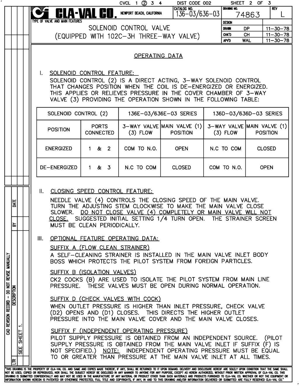
1 136-03/636-03
2
3
4

5 Description The CIa-VaI Model Hytrol Valve is a main valve for CIa-VaI Automatic Control Valves. It is a hydraulically operated, diaphragm-actuated, globe or angle pattern valve. This valve consists of three major components; body, diaphragm assembly, and cover. The diaphragm assembly is the only moving part. The diaphragm assembly uses a diaphragm of nylon fabric bonded with synthetic rubber. A synthetic rubber disc, contained on three and one half sides by a disc retainer and disc guide, forms a seal with the valve seat when pressure is applied above the diaphragm. The diaphragm assembly forms a sealed chamber in the upper portion of the valve, separating operating pressure from line pressure. Installation INSTALLATION / OPERATION / MAINTENANCE MODEL Hytrol Valve 1. Before valve is installed, pipe lines should be flushed of all chips, scale and foreign matter. 2. It is recommended that either gate or block valves be installed on both ends of the Hytrol Valve to facilitate isoiating the valve for preventive maintenance and repairs. 3. Place the valve in the line with flow through the valve in the direction indicated on the inlet nameplate. (See Flow Direction Section) Note: Valve can be installed in the vertical or horizontal position. 4. Allow sufficient room around valve to make adjustments and for disassembly. 5. CIa-VaI Hytrol Valves operate with maximum efficiency when mounted in horizontal piping with the cover UP, however, other positions are acceptable. Due to size and weight of the cover and internal components of 8 inch and larger valves, installation with the cover UP is advisable. This makes internal parts readily accessible for periodic inspection. 6. Caution must be taken in the installation of this valve to insure that galvanic and/or electrolytic action does not take place. The proper use of dielectric fittings and gaskets are required in all systems using dissimilar metals. 7. If a pilot control system is installed on the Hytrol Valve, use care to prevent damage. If it is necessary to remove fittings or components, be sure they are kept clean and replaced exactly as they were. 8. After the valve is installed and the system is first pressurized, vent air from the cover chamber and pilot system tubing by loosening fittings at all high points. Principles of Operation Three Way Pilot Control Three Way Pilot Control Restriction Modulating Control Tight Closing Operation When pressure from the valve inlet (or an equivalent independent operating pressure) is applied to the diaphragm chamber the valve closes drip-tight. Full Open Operation When pressure in diaphragm chamber is relieved to a zone of lower pressure (usually atmosphere) the line pressure (5 psi Min.) at the valve inlet opens the valve. Modulating Action Valve modulates when diaphragm pressure is held at an intermediate point between inlet and discharge pressure. With the use of a Cla-Val. "modulating control," which reacts to line pressure changes, the pressure above the diaphragm is varied, allowing the valve to throttle and compensate for the change.
6 Flow Direction The flow through the Hytrol Valve can be in one of two directions. When flow is up-and-over the seat, it is in normal flow and the valve will fail in the open position. When flow is overthe seat-and down, it is in reverse flow and the valve will fail in the closed position. There are no permanent flow arrow markings. The valve must be installed according to nameplate data. BRIDGEWALL INDlCATOR (cast into side of valve body) Normal Flow Troubleshooting Reverse Flow The following troubleshooting information deals strictly with the Model Hytrol Valve. This assumes that all other components of the pilot control system have been checked out and are in proper working condition. (See appropriate sections in Technical Manual for complete valve). Recommended Tools 1. Three pressure gauges with ranges suitable to the installation to be put at Hytrol inlet, outlet and cover connections. 2. Cla-Val Model X101 Valve Position Indicator. This provides visual indication of valve position without disassembly of valve. 3. Other items are: suitable hand tools such as screwdrivers, wrenches, etc. soft jawed (brass or aluminum) vise, 400 grit wet or dry sandpaper and water for cleaning. All trouble shooting is possible without removing the valve from the line or removing the cover. It is highly recommended to permanently install a Model X101 Valve Position Indicator and three gauges in unused Hytrol inlet, outlet and cover connections. SYMPTOM PROBABLE CAUSE REMEDY Fails to Close Closed isolation valves in control system, or in main line. Lack of cover chamber pressure. Open Isolation valves. Check upstream pressure, pilot system, strainer, tubing, valves, or needle valves for obstruction. Fails to Open Diaphragm damaged. (See Diaphragm Check.) Diaphragm assembly inoperative. Corrosion or excessive scale build up on valve stem. (See Freedom of Movement Check) Mechanical obstruction. Object lodged in valve. (See Freedom of Movement Check) Worn disc. (See Tight Sealing Check) Badly scored seat. (See Tight Sealing Check) Closed upstream and/or downstream isolation valves in main line. Insufficient line pressure. Replace diaphragm. Clean and polish stem. Inspect and replace any damaged or badly eroded part. Remove obstruction. Replace disc. Replace seat. Open isolation valves. Check upstream pressure. (Minimum 5 psi flowing line pressure differential.) Diaphragm assembly inoperative. Corrosion or excessive buildup on valve stem. (See Freedom of Movement Check) Diaphragm damaged. (For valves in "reverse flow" only) Clean and polish stem. Inspect and replace any damaged or badly eroded part. Replace diaphragm. After checking out probable causes and remedies, the following three checks can be used to diagnose the nature of the problem before maintenance is started. They must be done in the order shown. Three Checks The Hytrol Valve has only one moving part (the diaphragm and disc assembly). So, there are only three major types of problems to be considered. First: Valve is stuck - that is, the diaphragm assembly is not free to move through a full stroke either from open to close or vice versa. Second: Valve is free to move and can t close because of a worn out diaphragm. Third: Valve leaks even though it is free to move and the diaphragm isn t leaking. CAUTION: Care should be taken when doing the troubleshooting checks on the Hytrol Valve. These checks do require the valve to open fully. This will either allow a high flow rate through the valve, or the downstream pressure will quickly increase to the inlet pressure. In some cases, this can be very harmful. Where this is the case, and there are no block valves in the system to protect the downstream piping, it should be realized that the valve cannot be serviced under pressure. Steps should be taken to remedy this situation before proceeding any further. 2
7 Diaphragm Check (#1 ) 1. Shut off pressure to the Hytrol Valve by slowly closing upstream and downstream isolation valves. SEE CAUTION. 2. Disconnect or close all pilot control lines to the valve cover and leave only one fitting in highest point of cover open to atmosphere. 3.With the cover vented to atmosphere, slowly open upstream isolation valve to allow some pressure into the Hytrol Valve body. Observe the open cover tapping for signs of continuous flow. It is not necessary to fully open isolating valve. Volume in cover chamber capacity chart will be displaced as valve moves to open position. Allow sufficient time for diaphragm assembly to shift positions. If there is no continuous flow, you can be quite certain the diaphragm is sound and the diaphragm assembly is tight. If the fluid appears to flow continuously this is a good reason to believe the diaphragm is either damaged or it is loose on the stem. In either case, this is sufficient cause to remove the valve cover and investigate the leakage. (See Maintenance Section for procedure.) COVER CHAMBER CAPACITY (Liquid Volume displaced when valve opens) Valve size (inches) Displacement Gallons Liters 1 1/ / / Freedom of Movement Check (#2) 4. Determining the Hytrol Valve s freedom of movement can be done by one of two methods. 5. For most valves it can be done after completing Diaphragm Check (Steps 1, 2, and 3). SEE CAUTION. At the end of step 3 the valve should be fully open. 6. If the valve has a Cla-Val X101 Position Indicator, observe the indicator to see that the valve opens wide. Mark the point of maximum opening. 7. Re-connect enough of the control system to permit the application of inlet pressure to the cover. Open pilot system cock so pressure flows from the inlet into the cover. 8. While pressure is building up in the cover, the valve should close smoothly. There is a hesitation in every Hytrol Valve closure, which can be mistaken for a mechanical bind. The stem will appear to stop moving very briefly before going to the closed position. This slight pause is caused by the diaphragm flexing at a particular point in the valve s travel and is not caused by a mechanical bind. 9. When closed, a mark should be made on the X101 Valve position indicator corresponding to the closed position. The distance between the two marks should be approximately the stem travel shown in chart. STEM TRAVEL (Fully Open to Fully Closed) Valve Size (inches) Travel (inches) Inches MM Inches MM 1 1/ / / If the stroke is different than that shown in stem travel chart this is a good reason to believe something is mechanically restricting the stroke of the valve at one end of its travel. If the flow does not stop through the valve when in the indicated closed position, the obstruction probably is between the disc and the seat. If the flow does stop, then the obstruction is more likely in the cover. In either case, the cover must be removed, and the obstruction located and removed. The stem should also be checked for scale buildup. (See Maintenance, section for procedure.) 11. For valves 6 and smaller, the Hytrol Valve s freedom of movement check can also be done after all pressure is removed from the valve. SEE CAUTION. After closing inlet and outlet isolation valves and bleeding pressure from the valve, check that the cover chamber and the body are temporarily vented to atmosphere. Insert fabricated tool into threaded hole in top of valve stem, and lift the diaphragm assembly manually. Note any roughness. The diaphragm assembly should move smoothly throughout entire valve stroke. The tool is fabricated from rod that is threaded on one end to fit valve stem and has a T bar handle of some kind on the other end for easy gripping. (See chart in Step 4 of Disassembly Section.) 12. Place marks on this diaphragm assembly lifting tool when the valve is closed and when manually positioned open. The distance between the two marks should be approximately the stem travel shown in stem travel chart. If the stroke is different than that shown, there is a good reason to believe something is mechanically restricting the stroke of the valve. The cover must be removed, and the obstruction located and removed. The stem should also be checked for scale build-up. (See Maintenance Section for procedure.) Tight Sealing Check (#3) 13. Test for seat leakage after completing checks #1 & #2 (Steps 1 to 12). SEE CAUTION. Close the isolation valve downstream of the Hytrol Valve. Apply inlet pressure to the cover of the valve, wait until it closes. Install a pressure gauge between the two closed valves using one of the two ports in the outlet side of the Hytrol. Watch the pressure gauge. If the pressure begins to climb, then either the downstream isolation valve is permitting pressure to creep back, or the Hytrol is allowing pressure to go through it. Usually the pressure at the Hytrol inlet will be higher than on the isolation valve discharge, so if the pressure goes up to the inlet pressure, you can be sure the Hytrol is leaking. Install another gauge downstream of isolating valve. If the pressure between the valves only goes up to the pressure on the isolation valve discharge, the Hytrol Valve is holding tight, and it was just the isolation valve leaking. 3
8 Maintenance Preventative Maintenance The Cla-Val Co. Model Hytrol Valve requires no lubrication or packing and a minimum of maintenance. However, a periodic inspection schedule should be established to determine how the operating conditions of the system are affecting the valve. The effect of these actions must be determined by inspection. Disassembly Inspection or maintenance can be accomplished without removing the valve from the line. Repair kits with new diaphragm and disc are recommended to be on hand before work begins. WARNING: Maintenance personnel can be injured and equipment damaged if disassembly is attempted with pressure in the valve. SEE CAUTION. 1. Close upstream and downstream isolation valves and independent operating pressure when used to shut off all pressure to the valve. 2. Loosen tube fittings in the pilot system to remove pressure from valve body and cover chamber. After pressure has been released from the valve, use care to remove the controls and tubing. Note and sketch position of tubing and controls for re-assembly. The schematic in front of the Technical Manual can be used as a guide when reassembling pilot system. 3. Remove cover nuts and remove cover. If the valve has been in service for any length of time, chances are the cover will have to be loosened by driving upward along the edge of the cover with a dull cold chisel. VALVE STEM THREAD SIZE Valve Size Thread Size (UNF Internal) 1 1/4" 2 1/2" " 4" 1/4 28 6" 14" 3/ " 1/ / " 3/ / / The next item to remove is the stem nut. Examine the stem threads above the nut for signs of mineral deposits or corrosion. If the threads are not clean, use a wire brush to remove as much of the residue as possible. Attach a good fitting wrench to the nut and give it a sharp rap rather than a steady pull. Usually several blows are sufficient to loosen the nut for further removal. On the smaller valves, the entire diaphragm assembly can be held by the stem in a vise equipped with soft brass jaws before removing the stem nut. The use of a pipe wrench or a vise without soft brass jaws scars the fine finish on the stem. No amount of careful dressing can restore the stem to its original condition. Damage to the finish of the stem can cause the stem to bind in the bearings and the valve will not open or close. 6. After the stem nut has been removed, the diaphragm assembly breaks down into its component parts. Removal of the disc from the disc retainer can be a problem if the valve has been in service for a long time. Using two screwdrivers inserted along the outside edge of the disc usually will accomplish its removal. Care should be taken to preserve the spacer washers in water, particularly if no new ones are available for re-assembly. 7. The only part left in the valve body is the seat which ordinarily does not require removal. Careful cleaning and polishing of inside and outside surfaces with 400 wet/dry sandpaper will usually restore the seat s sharp edge. If, however, it is badly worn and replacement is necessary, it can be easily removed. On 6 and smaller valves block and tackle or a power hoist can be used to lift valve cover by inserting proper size eye bolt in place of the center cover plug. on 8 and larger valves there are 4 holes (5/8 11 size) where jacking screws and/or eye bolts may be inserted for lifting purposes. Pull cover straight up to keep from damaging the integral seat bearing and stem. COVER CENTER PLUG SIZE Valve Size Thread Size (NPT) 1 1/4" 1 1/2" 1/4" 2" 3" 1/2" 4" 6" 3/4" 8" 10" 1" 12" 1 1/4" 14" 1 1/2" 16" 2" 20 & 24" 2" 30 & Remove the diaphragm and disc assembly from the valve body. With smaller valves this can be accomplished by hand by pulling straight up on the stem so as not to damage the seat bearing. On large valves, an eye bolt of proper size can be installed in the stem and the diaphragm assembly can be then lifted with a block and tackle or power hoist. Take care not to damage the stem or bearings. The valve won't work if these are damaged. 4 Seats in valve sizes 1 1/4 through 6 are threaded into the valve body. They can be removed with accessory X109 Seat Removing Tool available from the factory. On 8 and larger valves, the seat is held in place by flat head machine screws. Use a tight-fitting, long shank screwdriver to prevent damage to seat screws. If upon removal of the screws the seat cannot be lifted out, it will be necessary to use a piece of angle or channel iron with a hole drilled in the center. Place it across the body so a long stud can be inserted through the center hole in the seat and the hole in the angle iron. By tightening the nut a uniform upward force is exerted on the seat for removal. NOTE: Do not lift up on the end of the angle iron as this may force the integral bearing out of alignment, causing the stem to bind. DO NOT LIFT VALVE SEAT VALVE BODY NUT ANGLE OR CHANNEL IRON LONG STUD OR BOLT NUT OR BOLT HEAD
9 Lime Deposits One of the easiest ways to remove lime deposits from the valve stem or other metal parts is to dip them in a 5-percent muriatic acid solution just long enough for the deposit to dissolve. This will remove most of the common types of deposits. CAUTlON: USE EXTREME CARE WHEN HANDLING ACID. Rinse parts in water before handling. If the deposit is not removed by acid, then a fine grit (400) wet or dry sandpaper can be used with water. Inspection of Parts After the valve has been disassembled, each part should be examined carefully for signs of wear, corrosion, or any other abnormal condition. Usually, it is a good idea to replace the rubber parts (diaphragm and disc) unless they are free of signs of wear. These are available in a repair kit. Any other parts which appear doubtful should be replaced. WHEN ORDERlNG PARTS, BE SURE TO GIVE COMPLETE NAMEPLATE DATA, ITEM NUMBER AND DESCRlPTlON. NOTE: If a new disc isn t available, the existing disc can be turned over, exposing the unused surface for contact with the seat. The disc should be replaced as soon as practical. Reassembly 1. Reassembly is the reverse of the disassembly procedure. If a new disc has been installed, it may require a different number of spacer washers to obtain the right amount of grip on the disc. When the diaphragm assembly has been tightened to a point where the diaphragm cannot be twisted, the disc should be compressed very slightly by the disc guide. Excessive compression should be avoided. Use just enough spacer washers to hold the disc firmly without noticeable compression. 2. MAKE SURE THE STEM NUT IS VERY TIGHT. Attach a good fitting wrench to the nut and give it a sharp rap rather than a steady pull. Usually several blows are sufficient to tighten the stem nut for final tightening. Failure to do so could allow the diaphragm to pull loose and tear when subjected to pressure. 3. Carefully install the diaphragm assembly by lowering the stem through the seat bearing. Take care not to damage the stem or bearing. Line up the diaphragm holes with the stud or bolt holes on the body. on larger valves with studs, it may be necessary to hold the diaphragm assembly up part way while putting the diaphragm over the studs. 4. Put spring in place and replace cover. Make sure diaphragm is Iying smooth under the cover. 5. Tighten cover nuts firmly using a cross-over pattern until all nuts are tight. 6. Test Hytrol Valve before re-installing pilot valve system. Test Procedure After Valve Assembly There are a few simple tests which can be made in the field to make sure the Hytrol Valve has been assembled properly. Do these before installing pilot system and returning valve to service. These are similar to the three troubleshooting tests. 1. Check the diaphragm assembly for freedom of movement after all pressure is removed from the valve. SEE CAUTlON. Insert fabricated tool into threaded hole in top of valve stem, and lift the diaphragm assembly manually. Note any roughness, sticking or grabbing. The diaphragm assembly should move smoothly throughout entire valve stroke. The tool is fabricated from rod that is threaded on one end to fit valve stem (See chart in Step 4 of Disassembly section.) and has a T Bar handle of some kind on the other end for easy gripping. Place marks on this diaphragm assembly lifting tool when the valve is closed and when manually positioned open. The distance between the two marks should be approximately the stem travel shown in stem travel chart. (See Freedom of Movement Check section.) If the stroke is different than that shown, there is a good reason to believe something is mechanically restricting the stroke of the valve. The cover must be removed, the obstruction located and removed. (See Maintenance Section for procedure.) Due to the weight of the diaphragm assembly this procedure is not possible on valves 8 and larger. on these valves, the same determination can be made by carefully introducing a low pressure-less than five psi) into the valve body with the cover vented. SEE CAUTION. Looking in cover center hole see the diaphragm assembly lift easily without hesitation, and then settle back easily when the pressure is removed. 2. To check the valve for drip-tight closure, a line should be connected from the inlet to the cover, and pressure applied at the inlet of the valve. If properly assembled, the valve should hold tight with as low as ten PSI at the inlet. See Tight Sealing Check section.) 3. With the line connected from the inlet to the cover, apply full working pressure to the inlet. Check all around the cover for any leaks. Re-tighten cover nuts if necessary to stop leaks past the diaphragm. 4. Remove pressure, then re-install the pilot system and tubing exactly as it was prior to removal. Bleed air from all high points. 5. Follow steps under Start-Up and Adjustment Section in Technical Manual for returning complete valve back to service. 5
10 INLET OUTLET 4 TOP VIEW GLOBE PATTERN PARTS LIST Item Description 1. Pipe Plug 2. Drive Screws (for nameplate) 3. Hex Nut (8 and larger) 4. Stud (8 and larger) 5. Cover Bearing 6. Cover 7. Stem Nut 8. Diaphragm Washer 9. Diaphragm 10. Spacer Washers 11. Disc Guide 12. Disc Retainer 13. Disc 14. Stem 15. Seat 16. Body 17. Spring 22. Flat Head Screws (8 and larger) 23. Seat O-Ring 24. Hex head Bolt (1 1/4 thru 4 ) 25. Nameplate 26. Upper Spring Washer (Epoxy coated valves only) 27. Lower Spring Washer (Epoxy coated valves only) 28. Cover Bearing Housing (16 only) 29. Cover O-Ring (16 only) 30. Hex Bolt (16 only) 31. Pipe Cap (16 only) INLET ANGLE PATTERN 9 31 OUTLET /4" - 6" SEAT DETAIL 8" - 24" SEAT DETAIL 16" COVER DETAIL 6

11 MODEL Description Hytrol Valve The CIa-VaI Model Hytrol Valve is a main valve for CIa-VaI Automatic Control Valves. It is a hydraulically operated, diaphragm-actuated, globe or angle pattern valve. This valve consists of three major components; body, diaphragm assembly, and cover. The diaphragm assembly is the only moving part. The diaphragm assembly uses a diaphragm of nylon fabric bonded with synthetic rubber. A synthetic rubber disc, contained on three and one half sides by a disc retainer and disc guide, forms a seal with the valve seat when pressure is applied above the diaphragm. The diaphragm assembly forms a sealed chamber in the upper portion of the valve, separating operating pressure from line pressure. INSTALLATION / OPERATION / MAINTENANCE Hytrol Valve Service Data Description Series Hytrol Valve The CIa-VaI Model Hytrol Valve (600 Series main valve) have only one part -the body- that is different from standard 100 Series Cla-Val main valve parts. The remaining parts of the 600 series main valve are standard Cla-Val main valve parts. All service and maintenance information for the standard 100 Series main valves also apply to the 600 series main valves. The most important thing to remember when ordering main valve repair kits and replacement parts, except for the body, all other parts are going to be for a smaller size main valve. Cla- Val identifies main valve parts with the flange size of the standard 100 Series main valve. Refer to the "Main Valve Sizes chart below. HYTROL SIZE Stem Travel Cover Capacity Displacement Valve Stem Thread UNF-Internal Cover Center Plug NPT HYTROL Service Data Cover Nut or Bolt Cover Lifting Thread Socket Qty Holes Thread Socket ft. Lbs. in. Lbs. Thread (Bolt) UNC Cover Plug Cover Torque Stem Nut Socket (Long) Stem Nut Torque (ft. Lbs.) inches mm inches mm inches mm Gallons Liters Lubed DRY 1" /4" 1/4" - 20 (B) 7/16" /8" /4" /4" 5/16" - 18 (B) 1/2" /16" /2" /4" 5/16" - 18 (B) 1/2" /16" " /2" 3/8" - 16 (B) 9/16" 8 3/8" 7/16" 12 1/2" /4" /2" /2" 7/16" - 14 (B) 5/8" 8 1/2" 9/16" 20 5/8" /16" " 80 4" /4-28 1/2" 1/2" - 13 (B) 3/4" 8 1/2" 9/16" 30 5/8" /16" " 100 6" /4-28 3/4" 3/4" - 10 (B) 1 1/8" 8 3/4" 5/8" 110 3/4" /16" " 150 8" /8-24 3/4" 3/4" - 10 (B) 1 1/8" 12 3/4" 5/8" 110 7/8" /16" " " /8-24 1" 3/4" /4" 16 5/8" " 13/16" /8" /16" " " /8-24 1" 7/8" /16" 20 3/4" " 13/16" /2" /8" " " / /4" 1 1/8" /16" 20 3/4" " 13/16" /2" /2" " / /2" 1 1/4" - 7 2" 20 1" - 8 1" 13/16" /2" /2" " ", 24" /2-20 2" 1 1/4" - 7 2" 20 1" - 8 1" 13/16" 545 2" " " / /2" 1 3/8" /8" 24 1" - 8 1" 13/16" /4" /2" 930 N/R 24" " /4-16 3/4" 1 1/2" /8" /8"- 7 1" 13/16" 800 3" - 12 Special 1350 N/R Adapter p/n E inside 1/4" - 28" Grade 5 Bolts "Heavy" Grade Nuts Tighten cover nuts in a "star" cross-over pattern Must Use ONLY Cla-Val Supplied part
12 4 1 4 BOLT/NUT TORQUING PROCEDURES ON VALVE COVERS 4 BOLTS BOLTS BOLTS Hytrol Main Valve Assembly COVER Cover Bolt 6" and Smaller SPRING PIPE PLUG COVER BEARING STEM NUT HEX NUT 8" and Larger PIPE PLUG DIAPHRAGM WASHER BOLTS BOLTS Follow this procedure when reassembling MAIN Valve: BOLTS KO Anti-Cavitation Trim Option KO DISC GUIDE DIAPHRAGM DISC DISC GUIDE DISC RETAINER SPACER WASHERS STEM 1. Tightens bolts/nuts in a Star or Cross-Over pattern following the numbers shown above to insure that cover seats evenly on the diaphragm material and body. KO SEAT SEAT Seat Screw 8" and Larger 2. Torque the bolt/nuts in three stages with a "Star" or "Cross-Over" pattern for each stage: SEAT O-RING STUD 8" and Larger A. To approximately 10% of final torque. B. To approximately 75% of final torque. C. To final required torque. BODY (Globe or Angle) PIPE PLUG 3. Valves that are to be tested to 375 PSI or higher should be retorqued after 24 hours. Repair Parts P.O. Box 1325 Newport Beach, CA Phone: Fax: claval@cla-val.com Website cla-val.com N (R-08/2014) CLA-VAL Copyright Cla-Val 2014 Printed in USA Specifications subject to change without notice.
13 INSTALLATION / OPERATION / MAINTENANCE MODEL (Reduced Internal Port) 600 Series Hytrol Valve SERVICE AND MAINTENANCE OF 600 SERIES VALVES The 600 series main valves have only one part -the body- that is different from standard 100 Series Cla-Val main valve parts. The remaining parts of the 600 series main valve are standard Cla- Val main valve parts. All service and maintenance information for the standard 100 Series main valves in this manual also apply to the 600 series main valves. The most important thing to remember when ordering main valve repair kits and replacement parts, except for the body, all other parts are going to be for a smaller size main valve. Cla-Val identifies main valve parts with the flange size of the standard 100 Series main valve. Refer to the "Main Valve Sizes Comparison" chart. For example, if you are servicing a 6" Hytrol and needed a repair kit, you would order a repair kit for a 4" Hytrol. This kit is also suitable for a 6" Hytrol. Complete Technical Manuals include a repair kit data sheet N-RK that shows this relationship. When you order repair parts, it is a good idea to include valve nameplate data (size, catalog number, and part number) and description of the parts desired. Do this to be sure parts will fit the valve you are working on and not be too big for it. Pilot controls and repair kits maintenance information remain the same for 100 or 600 Series valves. UNDERSTANDING THE 600 SERIES VALVES In 1987, Cla-Val introduced the Model Hytrol as the basic main valve for the 600 Series of automatic control valves. To identify all new valves using the Hytrol, an existing catalog number is modified. Making a 600 Series catalog number is simply done by using a "6" in front of the two digit catalog numbers or replacing the "2" with a "6" in three digit catalog numbers. Current schematics reflect both catalog numbers together separated by a slash ( i.e /690-01, 58-02/658-02, /610-01, etc). Since these two valves 'share' the same catalog number and schematic, they provide the same function in a system. The only difference between the two valves is the relative capacity of the two main valve series. The Hytrol is the basic main valve for Cla-Val automatic control valves. This valve is the current version of the Clayton Hytrol valve design originated in The Hytrol is designed as a full flow area valve. This means that the inlet, seat and outlet openings are the same size. Thus, the pressure drop is kept to a minimum for this globe style design. The Hytrol valve has all of the basic features and advantages of the original Hytrol. Only one part has been changed - the body. It is designed with different size inlet, seat and outlet openings. The Hytrol has inlet and outlet flanges one valve size larger than the seat opening size. This results in what is sometimes called a ''reduced port' main valve. For example, a 4" valve has a 3" seat. Note: valve size is always determined by the flange size. The following chart compares the and the main valves. Basic Main Valve Size Comparison Globe Pattern Valves Flange Size (inch) Seat Size (100 Series) (600 Series) Angle Pattern Valves Flange Size (inch) Seat Size (100 Series) (600 Series) The Hytrol is available only in ductile iron, 150 and 300 pressure class, and Bronze trim standard. Available extra cost main valve options include stainless steel trim, epoxy coating, Dura-Kleen stem, Delrin sleeved stem, and high temperature rubber parts. All four basic main valves have a 600 Series version available with all of the same benefits and size relationships. The following chart shows the relationship of Cla-Val main valve catalog numbers. Catalog Name Hytrol Powertrol Powercheck Hycheck Cla-Val Main Valves Catalog Number Circa Series 100 (Angle =2100) P & 100PA PC & 100PCA Series
14 PARTS LIST NO. DESCRIPTION 1 Pipe Plug 2 25 GLOBE INLET TOP VIEW OUTLET 2 Drive Screws (for nameplate) 3 Hex Nut (8" and larger) 4 Stud (8" and larger) 5 Cover Bearing 6 Cover 7 Stem Nut 8 Diaphragm Washer 9 Diaphragm 10 Spacer Washers 11 Disc Guide 12 Disc Retainer 13 Disc 14 Stem 15 Seat 16 Body 17 Spring 22 Flat Head Screws (10" and larger) 23 Seat O-Ring 24 Hex Bolt (3 " Thru 6") 25 Nameplate (Mounted on inlet flange) 26 Upper Spring Washer (Epoxy coated valves only) 27 Lower Spring Washer (Epoxy coated valves only) 28 Cover Bearing Housing (20" & 24" & 30") 29 Cover Bearing Housing O-Ring (20"& 24" & 30") 30 Hex Bolt (20" & 24") 31 Pipe Cap (20" & 24 & 30"") ANGLE INLET WHEN ORDERING PARTS, BE SURE TO GIVE COMPLETE NAMEPLATE DATA, ITEM NUMBER AND DESCRIPTION " 6" COVER DETAIL " 24" SEAT DETAIL 20" 24" COVER DETAIL CLA-VAL P.O. Box 1325 Newport Beach, CA Phone: Fax: claval@cla-val.com Website cla-val.com Copyright Cla-Val 2011 Printed in USA Specifications subject to change without notice. N (R-3/2011)
15 DESCRIPTION Bulletin 8320 is a small 3-way solenoid operated valve with all three pipe connections located in the body. The bodies are of brass or stainless steel construction. Standard valves have General Purpose, Nema Type 1 Solenoid Enclosures. Valves that are equipped with a solenoid enclosure which is designed to meet Nema Type 4-Water tight, Nema Type 7 (C or D) Hazardous Locations - Class I, Group C or D, and Nema Type 9 (E, F or G) Hazardous Locations - Class II, Group E, F or G are shown on separate sheets of Installation and Maintenance Instructions, Form Numbers V-5391 and V MANUAL OPERATORS (OPTIONAL) Valves with suffix "MO" or "MS" in catalog number are provided with a Manual Operator which allows manual operation when desired or during an interruption of electrical power. OPERATION Normally Closed: Applies pressure when solenoid is energized: exhausts pressure when solenoid is de-energized Normally Open: Applies pressure when solenoid is de-energized; exhausts pressure when solenoid is energized. Universal: For normally closed or normally open operation, selection or diversion of pressure can be applied at port 1 (A), 2 (B), or 3 (C). NORMALLY OPEN PRESS AT 3 (C) 3 (C) I (A) I (A) 3 (C) 2 (B) 2 (B) NORMALLY CLOSED PRESS AT 3 (C) I (A) I (A) 3 (C) 3 (C) 2 (B) 2 (B) INSTALLATION AND MAINTENANCE INSTRUCTIONS 3-WAY SOLENOID VALVES, NORMALLY OPEN NORMALLY CLOSED AND UNIVERSAL CONSTRUCTION UNIVERSAL-PRESS AT ANY ORIFICE. I (A) I (A) 3 (C) 3 (C) 2 (B) 2 (B) FORM SOLENOID DE- ENERGIZED SOLENOID ENERGIZED BULLETIN 8320 ASCO FORM NO. V5291R2 SOLENOID TEMPERATURE Standard catalog valves are supplied with coils designed for continuous duty service. When the solenoid is energized for a long period, the solenoid enclosure becomes hot and can be touched with the bare hand for only an instant. This safe operating temperature. Any excessive heating will be indicated by the smoke and odor of burning coil insulation. MAINTENANCE WARNING: Turn off electrical power and line pressure to valve before making repairs. It is not necessary to remove valve from pipe line for repairs. CLEANING A periodic cleaning of all valves is desirable. The time between cleanings will vary, depending on the media and service conditions. In general, if the voltage to the coils is correct, sluggish valve operation or excessive leakage will indicate that cleaning is required. IMPROPER OPERATION 1. Faulty Control Circuit: Check the electrical system by energizing the solenoid. A metallic click signifies the solenoid is operating. Absence of the click indicate loss of power supply. Check for loose or blown-out fuses, open-circuited or grounded coil, broken lead wires or splice. 2. Burned-out Coil: Check for open-circuited coil. Replace coil, if necessary. 3. Low Voltage: Check voltage across coil leads. Voltage must be at least 85% of nameplate ratings. 4. Incorrect Pressure: Check valve pressure. Pressure to valve must be within the range specified on nameplate. 5. Excessive Leakage: Disassemble valve and clean all parts. Replace parts that are worn or damaged with a complete Spare Parts Kit for best results. NOTE: Port Markings 1, 2, and 3 correspond directly to A, B and C. INSTALLATION Check Nameplate for correct Catalog Number, pressure, voltage and service. POSITIONING Valve may be mounted in any position PIPING Connect piping to valve according to markings on valve body. Refer to Flow Diagram provided. Apply pipe compound sparingly to male pipe threads only; if applied to valve threads, it may enter valve and cause operational difficulty. Pipe strain should be avoided by proper support and alignment of piping. When tightening pipe, do not use valve as lever. IMPORTANT: For protection of the solenoid valve, install a strainer or filter suitable for the service involved in the inlet side as close to the valve as possible. Periodic cleaning is required depending on the service conditions. WIRING Wiring must comply with local and National Electrical Codes. For valves equipped with an explosion-proof, watertight solenoid enclosure, the electrical fittings must be approved for use in the approved hazardous locations. Housings for all solenoids are made with connections for 1/2 inch conduit. The general purpose enclosure may be rotated to facilitate wiring by removing the retaining cap. NOTE Alternating Current (A-C) and Direct Current (D-C) solenoids are built differently. To convert from one to other, it is necessary to change the complete solenoid, including the core assembly. COIL REPLACEMENT (REF. FIG. 2) Turn off electrical power, disconnect coil lead wires and proceed as follows: 1. Remove retaining cap, nameplate and cover. 2. Slip yoke containing coil, sleeves and insulating washers off the solenoid base sub-assembly. Insulating washers are omitted when molded coil is used. In some D.C. Constructions, a single flux plate over the coil replaces yoke, sleeves and insulating washers. 3. Reassemble in reverse order of disassembly. VALVE DISASSEMBLY AND REASSEMBLY (REF. FIG. 2) Turn off electrical power supply and de-pressurize valve. 1. Remove retaining cap and slip entire solenoid off solenoid base subassembly or plugnut/core tube sub-assembly. 2. Unscrew bonnet or solenoid base sub-assembly. Remove core assembly, core spring and body gasket. 3. Remove end cap, body gasket, disc spring, disc holder, disc or disc holder assembly. 4. All parts are now accessible for cleaning or replacement. Replace worn or damaged parts with a complete Spare Parts Kit for best results. 5. Reassemble in reverse order of disassembly paying careful attention to exploded view provided. ORDERING INFORMATION FOR SPARE PARTS KITS When Ordering Spare Parts Kits or Coils Specify Valve Catalog Number, Serial Number and Voltage Spare Parts Kits and Coils are available for ASCO valves. Parts marked with
16 COVER RETAINING CAP NAMEPLATE PARTS INCLUDED IN SPARE PARTS KITS MANUAL OPERATOR SCREW TYPE (MS) MANUAL OPERATOR PUSH TYPE (MO) YOKE SLEEVE INSULATING WASHER (OMITTED WHEN MOLDED COIL IS USED) RETAINING CAP SOLENOID ENCLOSURE HOUSING COIL FLUX PLATE (NOT PRESENT IN ALL CONSTRUCTIONS) SOLENOID BASE SUB ASSEMBLY INSULATING WASHER (OMITTED WHEN MOLDED COIL IS USED) SLEEVE BONNET BONNET GASKET PLUGNUT/CORE TUBE SUB-ASSEMBLY (OPTIONAL) MOUNTING BRACKET (FOUR POSITIONS) TWO SELF-TAPPING SCREWS PROVIDED CORE SPRING (WIDE END IN CORE FIRST, CLOSED END PROTRUDES FROM TOP OF CORE) CORE ASSEMBLY BODY GASKET BODY (BRASS) CORE SPRING (WIDE END IN CORE FIRST, CLOSED END PROTUDES FROM TOP OF CORE) CORE ASSEMEBLY BODY GASKET BODY (ST. ST.) DISC HOLDER ASSEMBLY DISC SPRING BODY GASKET END CAP (OPTIONAL) MOUNTING BRACKET (SEE NOTE DISC HOLDER DISC DISC SPRING BODY GASKET END CAP NOTE: 1. FOR MOUNTING, A FLAT SURFACE MUST BE PROVIDED ACROSS THE ENTIRE LENGTH OF THE BRACKET. THE VALVE BODY BECOMES SECURE TO BRACKET, WHEN BRACKET IS TIGHTENED IN TO POSITION. IF THE VALVE HAS A MANUAL OPERATOR, A HOLE MUST BE MADE THROUGH THE MOUNTING SURFACE FOR THE OPERATOR STEM. CLA-VAL P.O. Box 1325 Newport Beach, CA Phone: Fax: claval@cla-val.com Website cla-val.com Copyright Cla-Val 2011 Printed in USA Specifications subject to change without notice. N-V5291 (R-3/2011)
17 -SERVICE NOTICE- ASCO solenoid valves with design change letter "G" in the catalog number (example: 8210G 1) have an epoxy encapsulated ASCO Red Hat II. solenoid. This solenoid replaces some of the solenoids with metal enclosures and open-frame constructions. Follow these installation and maintenance instructions if your valve or operator uses this solenoid. DESCRIPTION Catalog numbers 8016G1 and 8016G2 are epoxy encapsulated pull-type solenoids. The green solenoid with lead wires and 1/2 " conduit connection is designed to meet Enclosure Type 1 -General Purpose,Type 2- Dripproof,Types 3 and 3S-Raintight, and Types 4 and 4X-Watertight. The black solenoid on catalog numbers prefixed "EF" is designed to meet Enclosure Types 3 and 3S-Raintight, Types 4 and 4X-Watertight, Types 6 and 6P-Submersible, type 7 (A, B, C, & D) Explosionproof Class 1, Division 1, Groups A, B, C, & D and Type 9 (E, F, & G)-Dust-lgnitionproof Class 11, Division 1, Groups E, F, & G. The Class 11, Groups F & G Dust Locations designation is not applicable for solenoids or solenoid valves used for steam service or when a class "H" solenoid is used. See Temperature Limitations section for solenoid identification and nameplate/retainer for service. When installed just as a solenoid and not attached to an ASCO valve, the core has a UNF-2B tapped hole, 0.38 minimum full thread. Series 8016G solenoids are available in: Open-Frame Construction The green solenoid may be supplied with 1/4 spade, screw, or DIN terminals (Refer to Figure 4). Panel Mounted Construction These solenoids are specifically designed to be panel mounted by the customer through a panel having a.062 to.093 maximum wall thickness. (Refer to Figure 3 and section on Installation of Panel Mounted Solenoid). INSTALLATION AND MAINTENANCE INSTRUCTIONS OPEN-FLAME, GENERAL PURPOSE, WATERTIGHT/EXPLOSIONPROOF SOLENOIDS BULLETIN 8016G ASCO FORM NO. V6583R5 FOR BLACK ENCLOSURE TYPES 7 AND 9 ONLY CAUTION: To prevent fire or explosion, do not install solenoid and/or valve where ignition temperature is less than 165 C. On valves used for steam service or when a class "H" solenoid is used, do not install in hazardous atmosphere where ignition temperature is less than 180 C. See nameplate/retainer for service. NOTE: These solenoids have an internal non-resetable thermal fuse to limit solenoid temperature in the event that extraordinary conditions occur which could cause excessive temperatures. These conditions include high input voltage, a jammed core, excessive ambient temperature or shorted solenoid, etc. This unique feature is a standard feature is a standard feature only in solenoids with black explosionproof/dust-ignitionproof enclosures (types 7&9). IMPORTANT: To protect the solenoid valve or operator, install a strainer or filter, suitable for the service involved in the inlet side as close to the valve or operator as possible. Clean periodically depending on service condition & See ASCO Series 8600, 8601, and 8602 for strainers. Temperature Limitations For maximum valve ambient temperatures, refer to chart. The temperature limitations listed, only indicate maximum application temperatures for field wiring rated at 90 C. Check catalog number prefix and watt rating on nameplate to determine maximum ambient temperature. See valve installation and maintenance instructions for maximum fluid temperature. NOTE: For steam service, refer to Wiring section, Junction Box for temperature rating of supply wires. Temperature Limitations For Series 8016G Solenoids for use Valves Rated at 6.1, 8.1,9.1,10.6 or 11.1 Watts Watts Rating 6.1, 8.1, 9.1, & 11.1 Catalog Number Coil prefix None, FB, KF, KP, SF, SP, SC, & SD Class of Insulation Maximum ambient Temp. F F 125 Optional Features For Type 1 General Purpose Construction Only Junction Box This junction box construction meets Enclosure Types 2,3,3S,4, and 4X. Only solenoids with 1/4" spade or screw terminals may have a junction box. The junction box provides a 1/2 conduit connection, grounding and spade or screw terminal Connections within the junction box (See Figure 5). DIN Plug Connector Kit No. K Use this kit only for solenoids with DIN terminals. The DIN plug connector kit provides a two pole with grounding contact DIN Type construction (See Figure 6). OPERATION When the solenoid is energized, the core is drawn into the solenoid base subassembly. IMPORTANT: When the solenoid is de-energized, the initial return force for the core, Whether developed by spring, pressure, or weight, must exert a minimum force to overcome residual magnetism created by the solenoid. Minimum return force for AC construction is 11 ounces, and 4 ounces for DC construction. INSTALLATION Check nameplate for correct catalog number, service, and wattage. Check front of solenoid for voltage and frequency. WARNING: To prevent the possibility of electrical shock from the accessibility of live parts, install the open-frame solenoid in an enclosure. 6.1, 8.1, 9.1, & HB, HT, KB, KH, SS, ST, SU, & ST None, KF, SF, & SC HT, KH, SU, & ST H 140 F 104 H 104 Minimum ambient temperature -40 F (-40 C). Positioning Positioning This solenoid is designed to perform properly when mounted in any position. However, for optimum life and performance, the solenoid should be mounted vertically and upright to reduce the possibility of foreign matter accumulating in the solenoid base sub-assembly area. Wiring Wiring must comply with local codes and the National Electrical Code. All solenoids supplied with lead wires are provided with a grounding wire which is green or green with yellow stripes and a 1/2" conduit connection. To facilitate wiring, the solenoid may be rotated 360. For the watertight and explosionproof solenoid, electrical fittings must be approved for use in the approved hazardous locations. Additional Wiring Instructions For Optional Features: Open-Frame solenoid with 1/4" spade terminals For solenoids supplied with screw terminal connections use #12-18 AWG stranded copper wire rated at 90 C or greater. Torque terminal block screws to 10 ± 2 in-lbs (1,0 + 1,2 Nm). A tapped hole is provided in the solenoid for grounding, use a #Y10-32 machine screw. Torque grounding screw to 15-20
18 in-lbs (1,7-2,3 Nm). On solenoids with screw terminals, the socket head screw holding the terminal block to the solenoid is the grounding screw. Torque the screw to in-lbs (1,7-2,3 Nm). with a 5/32" hex key wrench. Junction Box The junction box is used with spade or screw terminal solenoids only and is provided with a grounding screw and a 1/2" conduit connection. Connect #12-18AWG standard copper wire only to the screw terminals. Within the junction box use field wire that is rated 90 C or greater for connections. For steam service use 105 C rated wire up to 50 psi or use 125 C rated wire above 50 psi. After electrical hookup, replace cover gasket, cover, and screws. Tighten screws evenly in a crisscross manner. DIN Plug Connector Kit No. KC The open frame solenoid is provided with DIN terminals to accommodate the DIN plug connector kit. 2. Remove center screw from plug connector. Using a small screwdriver, pry terminal block from connector cover. 3. Use #12-18 AWG stranded copper wire rated at 90 C or greater for connections. Strip wire leads back approximately 1/4" for installation in socket terminals. The use of wire-end sleeves is also recommended for these socket terminals. Maximum length of wire-end sleeves to be approximately 1/4". Tinning of the ends of the lead wires is not recommended. 4. Thread wire through gland nut, gland gasket, washer, and connector cover. NOTE: Connector cover may be rotated in 90 increments from position shown for alternate positioning of cable entry. 5. Check DIN connector terminal block for electrical markings. Then make electrical hookup to terminal block according to markings on it. Snap terminal block into connector cover and install center screw. 6. Position connector gasket on solenoid and install plug connector. Torque center screw to 5 ± 1 in-lbs (0,6 ± 1,1 Nm). NOTE: Alternating current (AC) and direct current (DC) solenoids are built differently. To convert from one to the other, it may be necessary to change the complete solenoid including the core and solenoid base subassembly, not just the solenoid. Consult ASCO. Installation of Solenoid Solenoids may be assembled as a complete unit. Tightening is accomplished by means of a hex flange at the base of the solenoid. The 3/4" bonnet construction (Figure 1) must be disassembled for installation and installed with a special wrench adapter. Installation of Panel Mounted Solenoid (See Figure 3) Disassemble solenoid following instruction under Solenoid Replacement then proceed 3/4" Valve Bonnet Construction 1. Install retainer(convex side to solenoid) in diameter mounting hole in customer panel. 2. Then position spring washer over plugnut/core tube sub-assembly. 3. Install plugnut/core tube sub-assembly through retainer in customer panel. Then replace solenoid, nameplate/retainer and red cap. 15/16" Valve Bonnet Construction 1. Install solenoid base sub-assembly through 0.69 diameter mounting hole in customer panel. 2. Position spring washer on opposite side of panel over solenoid base sub-assembly then replace. Solenoid Temperature Standard solenoids are designed for continuous duty service. When the solenoid is energized for a long period, the solenoid becomes hot and can be touched by hand only for an instant. This is a safe operating temperature. MAINTENANCE WARNING: To prevent the possibility of personal injury or property damage, turn off electrical power, depressurize solenoid operator and/or valve, and vent fluid to a safe area before servicing. All solenoid operators and valves should be cleaned periodically. The time between cleaning will vary depending on medium and service conditions. In general, if the voltage to the solenoid is correct, sluggish valve operation, excessive noise or leakage will indicate that cleaning is required. Clean strainer or filter when cleaning the valve, Preventive Maintenance Keep the medium flowing through the solenoid operator or valve as free from dirt and foreign material as possible. While in service, the solenoid operator or valve should be operated at least once a month to insure proper opening and closing. Depending on the medium and service conditions, periodic inspection of internal valve parts for damage or excessive wear is recommended. Thoroughly clean all parts. Replace any worn or damaged parts. Causes of Improper Operation Faulty Control Circuit: Check the electrical system by energizing the solenoid. A metallic click signifies that the solenoid is operating. Absence of the click indicates loss of power supply. Check for loose or blown fuses, open-circuited or grounded solenoid, broken lead wires or splice connections. Burned-Out Solenoid: Check for open-circuited solenoid. Replace if necessary. Check supply voltage; it must be the same as specified on nameplate/retainer and marked on the solenoid. Check ambient temperature and check that the core is not jammed. Low Voltage: Check voltage across the solenoid leads. Voltage must be at least 85% of rated voltage. Solenoid Replacement 1. On solenoids with lead wires disconnect conduit, coil leads, and grounding wire. NOTE: Any optional parts attached to the old solenoid must be reinstalled on the new solenoid. 2. Disassemble solenoids with optional features as follows: Spade or Screw Terminals Remove terminal connections, grounding screw, grounding wire, and terminal block (screw terminal type only). NOTE: For screw terminals, the socket head screw holding the terminal block serves as a grounding screw. Junction Box Remove conduit and socket head screw (use 5132" hex key wrench) from center of junction box. Disconnect junction box from solenoid. DIN Plug Connector Remove center screw from DIN plug connector. Disconnect DIN plug connector from adapter. Remove socket head screw (use 5/32" hex key wrench), DIN terminal adapter, and gasket from solenoid. 3. Snap off red cap from top of solenoid base sub-assembly. 4. Push down on solenoid. Then using a suitable screwdriver, insert blade in slot provided between solenoid and nameplate/retainer. Pry up slightly and push to remove. Then remove solenoid from solenoid base sub-assembly. 5. Reassemble using exploded views for parts identification and placement Disassembly and Reassembly of Solenoids 1. Remove solenoid, see Solenoid Replacement. 2. Remove finger washer or spring washer from solenoid base sub-assembly. 3. Unscrew solenoid base sub-assembly. NOTE: Some solenoid constructions have a plugnut/core tube sub-assembly, bonnet gasket and bonnet in place of the solenoid base sub-assembly. To remove bonnet use special wrench adapter supplied in ASCO Rebuild Kit. For wrench adapter only, order ASCO Wrench Kit No.K The core is now accessible for cleaning or replacement. 5. If the solenoid is part of a valve, refer to basic valve installation and maintenance instructions for further disassembly. 6. Reassemble using exploded views for identification and placement of parts. ORDERING INFORMATION FOR ASCO SOLENOIDS When Ordering Solenoids for ASCO Solenoid Operators or Valves, order the number stamped on the solenoid. Also specify voltage and frequency. Cleaning
19 Part Name solenoid base sub-assembly valve bonnet (3/4" bonnet constructions) bonnet screw (3/8" or 1/2" NPT pipe size) bonnet screw (3/4" NPT pipe size) Torque Chart Torque Value in inch-pounds 175 ± ± Torque Value in Newton-Meters 19.8 ± ± wave washer valve bonnet bonnet gasket core Remove red cap and push solenoid down. Then pry here to lift nameplate/retainer and push to remove. solenoid with 1/2" NPT For special wrench adapter order kit No. K UN-2A thread plugnut/core tube sub-assembly Tapped hole in core UNF-2B 0.38 minimum full thread. core (AC) red cap nameplate/ retainer 3/4" Bonnet Construction 15/16" Bonnet Construction grounding wire - green or green with yellow stripes spring washer solenoid base sub-assembly UNS -2A thread core (DC) Figure 1. Series 8016G solenoids Side View collar to face valve body Remove red cap and push solenoid down. Then pry here to lift nameplate/retainer and push to remove. Alternate Construction finger washer See torque chart for bonnet screws red cap nameplate/ retainer spacer red cap nameplate/retainer solenoid with 1/2" NPT grounding wire - green or green with yellow stripes Remove red cap and push solenoid down. Then pry here to lift nameplate/retainer and push to remove. solenoid diameter mounting hole finger washer finger washer valve bonnet core tube retainer spring washer valve bonnet bonnet gasket.062 to.093 maximum thickness of panel for mounting For special wrench adapter order kit No. K plugnut/core tube sub-assembly solenoid base sub-assembly core 0.69 diameter mounting hole core Bolted Bonnet Construction 3/4" Bonnet Construction 15/16" Bonnet Construction Figure 2. Series 8016G solenoid Figure 3. Series 8016G panel mounted solenoids
20 Part Name terminal block screws socket head screw center screw Torque Chart Torque Value in inch-pounds 10 ± ± 1 Torque Value in Newton-Meters 1,1 ± 0,2 1,7-2,3 0,6 ± 0,1 Open Frame Solenoid with 1/4" Spade Terminals See torque chart above Open-Frame Solenoid with Screw Terminals. Socket head screw is used for grounding. Screw terminal adapter Open-Frame Solenoid with DIN Terminals. gasket DIN terminal adapter tapped hole for #10-32 grounding screw (not included) socket head grounding screw (5/32" hex key wrench) terminal block screw socket head screw (5/32" hex key wrench) Figure 4. Open - frame solenoids Junction box Solenoid with 1/4" Spade Terminals or Screw Terminals screw terminal block (see note) cover screw cover See torque chart above cover gasket Note: Junction box with screw terminals shown. With screw terminal block removed, remaining parts comprise the junction box for spade terminal construction. junction box gasket junction box with 1/2" conduit connection and grounding terminal grounding screw and cup washer socket head screw (5/32" hex key wrench) Figure 5. Open - frame solenoids Notes: Open-Frame Solenoid with DIN Terminal Plug Connector See torque chart above 1. Connector cover may be rotated in 90 increments from position shown for alternate postion of cable entry. 2. Refer to markings on DIN connector for proper electrical connections. gasket socket head screw (5/32" hex key wrench) DIN connector terminal block (see note 2) DIN terminal adapter connector gasket connector cover (see note 1) Indicates that these parts are included in DIN plug connector Kit No. K gland nut gland gasket washer center screw CLA-VAL P.O. Box 1325 Newport Beach, CA Phone: Fax: claval@cla-val.com Website cla-val.com Copyright Cla-Val 2011 Printed in USA Specifications subject to change without notice. N-V6583 (R-3/2010)
21
22 PARTS LIST CN Globe and Angle Needle Valves CN Series CAT. NO. CNA ANGLE CAT. NO. CNB GLOBE WHEN USED AS A CONTROL VALVE, HANDWEEL IS REMOVED AND STEM IS SLOTTED FOR SCREW- DRIVER ADJUSTMENT. 4 3/4" SIZE ONLY When ordering parts, please specify: All nameplate data Description Part Number Item Number Material Item Description 1. Body 2. Bonnet 3. Stem 4. Gland 5. Nut 6. Handwheel 7. Nut 8. Packing CLA-VAL P.O. Box 1325 Newport Beach, CA Phone: Fax: claval@cla-val.com Website cla-val.com Copyright Cla-Val 2011 Printed in USA Specifications subject to change without notice. PL- CN (R-3/2011)


23 INSTALLATION / OPERATION / MAINTENANCE Self Scrubbing Cleaning Action Straight Type or Angle Type MODEL X46 Flow Clean Strainer X46B Angle X46A Straight The Cla-Val Model X46 Strainer is designed to prevent passage of foreign particles larger than.015". It is especially effective against such contaminant as algae, mud, scale, wood pulp, moss, and root fibers. There is a model for every Cla-Val. valve. The X46 Flow Clean strainer operates on a velocity principle utilizing the circular "air foil" section to make it self cleaning. Impingement of particles is on the "leading edge" only. The low pressure area on the downstream side of the screen prevents foreign particles from clogging the screen. There is also a scouring action, due to eddy currents, which keeps most of the screen area clean. Dimensions (In Inches) H C SAE B Male Pipe G I A X46B E Female D Pipe X46 Angle Type B (In Inches) B(NPT) C(SAE) D E H I 1/8 1/4 1-3/8 5/8 7/8 1/4 1/4 1/4 1-3/4 3/4 1 3/8 3/8 1/4 2 7/8 1 1/2 3/8 3/8 1-7/8 7/8 1 1/2 1/2 3/8 2-3/ /4 5/8 Width Across Flats F D B E X46A When Ordering, Please Specify: Male Pipe Catalog Number X46 Straight Type or Angle Type Size Inserted Into and Size Connection Materials I X46A Straight Type A (In Inches) A (NPT) B (NPT) D E F G I 1/8 1/8 1-3/4 3/4 1/2 1/2 1/4 1/4 1/4 2-1/4 1 3/4 3/4 3/8 3/8 3/8 2-1/2 1 7/8 7/8 1/2 3/8 1/2 2-1/2 1-1/4 1/2 7/8 3/4 1/2 1/ / /8 3/4 3/8 3/4 3-3/8 2 1/2 1 7/8 3/4 3/ /2 7/8 3/ /4 2-3/4 1/2 1-3/8 7/ /2 2-3/4 1-1/4 1-3/4 7/8 1/ /4 2-3/4 1/2 1-3/8 7/8 INSTALLATION The strainer is designed for use in conjunction with a Cla-Val Main Valve, but can be installed in any piping system where there is a moving fluid stream to keep it clean. When it is used with the Cla-Val Valve, it is threaded into the upstream body port provided for it on the side of the valve. It projects through the side of the Main Valve into the flow stream. All liquid shunted to the pilot control system and to the cover chamber of the Main Valve passes through the X46 Flow Clean Strainer. INSPECTION Inspect internal and external threads for damage or evidence of cross-threading. Check inner and outer screens for clogging, embedded foreign particles, breaks, cracks, corrosion, fatigue, and other signs of damage. DISASSEMBLY Do not attempt to remove the screens from the strainer housing. CLEANING After inspection, cleaning of the X46 can begin. Water service usually will produce mineral or lime deposits on metal parts in contact with water. These deposits can be cleaned by dipping X46 in a 5-percent muriatic acid solution just long enough for deposit to dissolve. This will remove most of the common types of deposits. Caution: use extreme care when handling acid. If the deposit is not removed by acid, then a fine grit (400) wet or dry sandpaper can be used with water. Rinse parts in water before handling. An appropriate solvent can clean parts used in fueling service. Dry with compressed air or a clean, lint-free cloth. Protect from damage and dust until reassembled. REPLACEMENT If there is any sign of damage, or if there is the slightest doubt that the Model X46 Flow Clean Strainer may not afford completely satisfactory operation, replace it. Use Inspection steps as a guide. Neither inner screen, outer screen, nor housing is furnished as a replacement part. Replace Model X46 Flow Clean Strainer as a complete unit. When ordering replacement Flow-Clean Strainers, it is important to determine pipe size of the tapped hole into which the strainer will be inserted (refer to column A or F), and the size of the external connection (refer to column B or G). CLA-VAL P.O. Box 1325 Newport Beach, CA Phone: Fax: claval@cla-val.com Website cla-val.com Copyright Cla-Val 2011 Printed in USA Specifications subject to change without notice. N-X46 (R-3/2011)
24 CLA-VAL P.O. Box 1325 Newport Beach, CA Phone: Fax: Website cla-val.com Copyright Cla-Val 2011 Printed in USA Specifications subject to change without notice. PL-CK2 (R-3/2011)
 Pressure Range Part Number 0-60 psi 20534301 A 0-100 psi 20534302K 0-160 psi 20534311J 0-200 psi 20534303J 0-300")
25 MODEL X141 Cla-Val Gauge Option Liquid-Filled Dual Scale (PSI / BAR) Long Life Stainless Steel Construction Tamper-Resistant Design 2 1 2" and 4" Diameter Sizes Available Pressure Ranges Model X141 4" Pressure Gauge X141 Gauge Assembly for 6" and smaller valves (2 1/2" Diameter Dial) Pressure Range Part Number 0-60 psi A psi K psi J psi J psi H psi G X141 Gauge Assembly for 8" and larger valves (4" Diameter Dial) Pressure Range Part Number 0-60 psi F psi E psi D psi C psi K Isolation Valve Included The Cla-Val Model X141 Pressure Gauge Option consists of glycerin-filled pressure gauges with Cla-Val Logo installed with 1 4 CK2 Bronze Isolation Valves on main valve inlet and outlet. Gauges are waterproof, shock resistant, and fully enclosed with Stainless Steel case and Bronze wetted parts. All gauges have dual scale (PSI/BAR) and 1.5% F.S. accuracy with 1/4" NPT bottom connection " Diameter Dial supplied with 6" and smaller valves. 4" Diameter Dial supplied with 8" and larger valves. Available installed on new valves and must be specified on customer Purchase Order. Other materials available - consult factory. Typical Installation of X141 Typical Installation of X141 Both Gauges Installed Specify desired pressure range and valve location (inlet or outlet) on order. CLA-VAL P.O. Box 1325 Newport Beach, CA Phone: Fax: claval@cla-val.com Website cla-val.com Copyright Cla-Val 2012 Printed in USA Specifications subject to change without notice. E-X141 (R-7/2012)
 Pressure Range Part Number 0-60 psi 20534301 A 0-100 psi 20534302K 0-160 psi 20534311J 0-200")

 and 1.5% F.S. accuracy with 1/4\" NPT bottom connection. 2 1 2\" Diameter Dial supplied with 6\" and smaller valves.")
26 PARTS LIST X141 Cla-Val 2 1 2" & 4" Gauge Option Liquid-Filled Dual Scale (PSI / BAR) Long Life Stainless Steel Construction Tamper-Resistant Design 2 1 2" and 4" Diameter Sizes Available Pressure Ranges Model X141 4" Pressure Gauge X141 Gauge Assembly for 6" and smaller valves (2 1/2" Diameter Dial) Pressure Range Part Number 0-60 psi A psi K psi J psi J psi H psi G X141 Gauge Assembly for 8" and larger valves (4" Diameter Dial) Pressure Range Part Number 0-60 psi F psi E psi D psi C psi K Isolation Valve Included The Cla-Val Model X141 Pressure Gauge Option consists of liquid-filled pressure gauges with Cla-Val Logo installed with 1 4 CK2 Bronze Isolation Valves on main valve inlet and outlet. Gauges are waterproof, shock resistant, and fully enclosed with Stainless Steel case and Bronze wetted parts. All gauges have dual scale (PSI/BAR) and 1.5% F.S. accuracy with 1/4" NPT bottom connection " Diameter Dial supplied with 6" and smaller valves. 4" Diameter Dial supplied with 8" and larger valves. Available installed on new valves and must be specified on customer Purchase Order. Other materials available consult factory. Typical Installation of X141 Typical Installation of X141 Both Gauges Installed Specify desired pressure range and valve location (inlet or outlet) on order. CLA-VAL P.O. Box 1325 Newport Beach, CA Phone: Fax: claval@cla-val.com Website cla-val.com Copyright Cla-Val 2011 Printed in USA Specifications subject to change without notice. PL-X141 Gauge Option (R-3/2011)
27 MODEL X101 Valve Position Indicator & Pilot System Components Positive Visual Indicator Frictionless Leak Proof Easy Maintenance and Cleaning Protected Indicator Rod The Cla-Val Model X101 Visual Position Indicator is designed to display Cla-Val valve position quickly and easily. A solid brass indicator rod fastened directly to the valve stem moves up and down inside a pyrex tube. The tube is contained within a brass housing which is open on two opposite sides to permit clear vision of the indicator rod. To purge air that may be trapped in the valve cover, a vent valve in the top of the housing is provided. Model X101 valve position indicator is furnished complete for installation on specified size Cla-Val Automatic Control Valve. Dimensions Specifications Vent Valve Sizes: 1" thru 24" Materials: Brass, Pyrex Tube Gasket VALVE A B SIZE INCHES NPT 1" /4" Pressure Rating: Optional Material: 400 psi Stainless Steel Housing 1 1/4" /4" A Vent Valve Closed Sight Tube Gasket Adapter Bushing 1 1/2" /4" 2" /2" 2 1/2" /2" 3" /2" 4" " 6" " 8" " Installation Can be installed on any Cla-Val basic main valve in a few minutes. Simply replace the fitting on top of the valve cover with the indicator assembly. B NPT Valve Cover 10" " 12" /4" 14" /2" When Ordering, Please Specify 1. Valve Size Stem Stem Adapter Valve Stem 16" " 20" " 24" " 2. Catalog No. X Valve Series No. (Appears on Valve Nameplate) 4. Optional Material Stainless Steel Dimension "A" is height added to valve by indicator assembly


 CLA-VAL PO Box 1325 Newport")


28 CSM-11 Solenoid Control CDS6A Altitude Control Standard: Body Material Bronze with Monel Trim Wetted Body Material Standard: Bronze with Stainless Steel Trim Option: Bronze with Stainless Steel Trim No. of Springs Altitude Ranges ft ft ft ft ft CDC-1 Check Valve CSC Swing Check Valve Size Body Material Trim Material 3/8"-1/2" Brass Delrin Size Body Material Trim Material 3/8"-1" Brass Brass/Buna N CN Series - Needle Valves CK Series - Isolation Valve Size Body Material Trim Material 1/4"-1" Standard: Bronze Brass Option: Stainless Steel Stainless Steel Size Body Material Trim Material 3/8"-1" Standard: Bronze Stainless Steel/Teflon Option: Stainless Steel Stainless Steel/Teflon E-X101 (R-3/2014) CLA-VAL PO Box 1325 Newport Beach CA Phone: Fax: CLA-VAL CANADA 4687 Christie Drive Beamsville, Ontario Canada L0R 1B4 Phone: Fax: COPYRIGHT CLA-VAL 2014 Printed in USA Specifications subject to change without notice. CLA-VAL EUROPE Chemin dés Mesanges 1 CH-1032 Romanel/ Lausanne, Switzerland Phone: Fax: Represented By:
Three Way Pilot Control
 Description The CIa-VaI Model 00-0 Hytrol Valve is a main valve for CIa-VaI Automatic Control Valves. It is a hydraulically operated, diaphragm-actuated, globe or angle pattern valve. This valve consists
INSTALLATION / OPERATION / MAINTENANCE MODEL SERVICE AND MAINTENANCE OF 600 SERIES VALVES UNDERSTANDING THE 600 SERIES VALVES
 INSTALLATION / OPERATION / MAINTENANCE MODEL 100-20 (Reduced Internal Port) 600 Series Hytrol Valve SERVICE AND MAINTENANCE OF 600 SERIES VALVES The 600 series main valves have only one part -the body-
 43-01/643-01 Description The CIa-VaI Model 100-01 Hytrol Valve is a main valve for CIa-VaI Automatic Control Valves. It is a hydraulically operated, diaphragm-actuated, globe or angle pattern valve.
Typical Applications. Installation
 124-01/624-01 Schematic Diagram Item Description 1 Hytrol (Main Valve) 2 CF1-C1 Float Control (Sizes 1/2"-6") 124-01 (Full Internal Port) MODELS (Sizes 3"-8") 624-01 (Reduced Internal Port) Float Valve
Installation & Maintenance Instructions
 Installation & Maintenance Instructions OPEN-- FRAME, GENERAL PURPOSE, WATERTIG/EXPLOSIONPROOF SOLENOIDS r SERIES 8016G/H (Section1of2) SERVICE NOTICE ASCOr solenoid valves with design change letter G
4 - Way Control 4 - Way Control 4 - Way Control with lock
 INSTALLATION / OPERATION / MAINTENANCE 1. DESCRIPTION MODEL 0-02 (Full Internal Port) Powertrol Valve This manual contains information for installation, operation and maintenance of the Cla-Val Co. 0-02
Float Valve MODEL. Schematic Diagram. Optional Features. Typical Applications
 129-01/629-01 Schematic Diagram Item Description 1 Hytrol (Main Valve) 2 X47A Ejector 3 Bell Reducer 4 CFM2 Float Control MODEL Float Valve Accurate and Repeatable Level Control Proportional Flow Reliable
79488 J Model 50-01/650-01
 50-01/650-01 TM 79488 J Model 50-01/650-01 Pressure Relief Valve (Equipped with Closing Speed Control) 11-30-78 11-30-78 11-30-78 JD CH WAL P1 B1 D1 REMOTE SENSING F INLET NOT FURNISHED BY CLA-VAL CO.
Three Way Pilot Control
 390-07/3690-07 Description The CIa-VaI Model 100-01 Hytrol Valve is a main valve for CIa-VaI Automatic Control Valves. It is a hydraulically operated, diaphragm-actuated, globe or angle pattern valve.
Distributed By: M&M Control Service, Inc /650-90
 50-90/650-90 Distributed By: M&M Control Service, Inc. Phone: 800-876-0036 Fax: 847-356-0747 Email: sales@mmcontrol.com Description The CIa-VaI Model 100-01 Hytrol Valve is a main valve for CIa-VaI
 138-01/638-01 MODEL 100-01 (Sizes 3/8"-36") Hytrol Valve Drip-Tight, Positive Seating Service Without Removal From Line Threaded, Flanged or Grooved Ends Globe or Angle Pattern 100% Factory Tested
 210-16/610-16 Description The CIa-VaI Model 100-01 Hytrol Valve is a main valve for CIa-VaI Automatic Control Valves. It is a hydraulically operated, diaphragm-actuated, globe or angle pattern valve.
50B-5KG/2050B-5KG. Distributed By: M&M Control Service, Inc. Phone: Fax:
 0B-KG/200B-KG Distributed By: M&M Control Service, Inc. Phone: 00-7-003 Fax: 7-3-077 Email: sales@mmcontrol.com MODEL 0B-KG Pump Suction Control Valve Adjustable Opening Speed For Pump Suction Protection
Pressure Reducing Valve with Low Flow By-Pass MODEL. Schematic Diagram. Optional Features. Typical Applications
 90-99 MODEL 90-99 (Full Internal Port) Pressure Reducing Valve with Low Flow By-Pass Schematic Diagram Item Description 1 90-01 Pressure Reducing Valve 1-1 Hytrol (Main Valve) 1-2 X58C Restriction Tube
Distributed By: M&M Control Service, Inc KO/650-01KO
 50-01KO/650-01KO INTRODUCTION The Cla-Val 50-01/650-01 is an automatic control valve designed to maintain constant upstream pressure to close limits. It is a hydraulically operated, pilot controlled, modulating
 0-0/0-0 Description The CIa-VaI Model 00-0 Hytrol Valve is a main valve for CIa-VaI Automatic Control Valves. It is a hydraulically operated, diaphragm-actuated, globe or angle pattern valve. This
MODEL. Schematic Diagram. Optional Features. Typical Applications
 9-0/9-0 MODEL 9-0 (Full Internal Port) 9-0 (Reduced Internal Port) Electronic Actuated Rate of Flow and Pressure Reducing Valve Schematic Diagram Item Description Hytrol (Main Valve) X8C Restriction
124-01/ Distributed By: M&M Control Service, INC. Phone: Fax:
 124-01/624-01 Distributed By: M&M Control Service, INC. Phone: 800-876-006 Fax: 847-56-0747 Email: Sales@mmcontrol. INSTALLATION / OPERATION / MAINTENANCE MODEL 124-01 624-01 Float Valve Description The
81-01/ Check Valve
 8-0 MODEL INSTALLATION / OPERATION / MAINTENANCE 8-0/68-0 Check Valve INTRODUCTION The Cla-Val Model 8-0/68-0 Check Valve is an automatic valve designed to close drip tight when outlet pressure exceeds
QTY ADDED TO CATALOG NUMBER
 50B-KG/050B-KG TLC --9 JB -7-97 BF 0-8- MS 9-- TYPE OF VALVE AND MAIN FEATURES CVCL NOT FURNISHED BY CLA-VAL CO. DIST. CODE 050 CATALOG NO. 50B-KG (GLOBE) 050B-KG (ANGLE) PRESSURE RELIEF VALVE FACTORY
INSTALLATION AND MAINTENANCE INSTRUCTIONS 3-WAY SOLENOID VALVES, NORMALLY OPEN NORMALLY CLOSED AND UNIVERSAL CONSTRUCTION
 134-05 DESCRIPTION Bulletin 8320 is a small 3-way solenoid operated valve with all three pipe connections located in the body. The bodies are of brass or stainless steel construction. Standard valves
Cla-Val. Service Training Manual. Simple solutions plus learning with a purpose
 Cla-Val Service Training Manual Simple solutions plus learning with a purpose 5 Application Series Section General Identify What Valve You Have 5-1 Rate of Flow 40 Series 5-2 Pressure Relief 50 Series
SERIES ASCO Valves DESCRIPTION OPERATION INSTALLATION. Positioning. Page1of5(Section1of2) I&M No.V9575R3 (Section1of2)
 I&M No.V9575R3 (Section1of2)") Installation & Maintenance Instructions -- WAY DIRECT-- ACTING SOLENOID VALVES REVISION H & R NORMALLY OPEN OR NORMALLY CLOSED OPERATION BRASS OR STAINLESS STEEL CONSTRUCTION -- 1/8I, 1/4I, OR3/8I PIPE
Installation & Maintenance Instructions -- WAY DIRECT-- ACTING SOLENOID VALVES REVISION H & R NORMALLY OPEN OR NORMALLY CLOSED OPERATION BRASS OR STAINLESS STEEL CONSTRUCTION -- 1/8I, 1/4I, OR3/8I PIPE
50B-5KG. Pump Suction Control Valve MODEL. Specifications. Typical Installation. Adjustable Opening Speed For Pump Suction Protection
 0B-KG MODEL 0B-KG Pump Suction Control Valve Adjustable Opening Speed For Pump Suction Protection Pilot Control Provides Wide Flow Range With Minimal Pressure Variations Controlled Closing For System
Airsweep Installation & Maintenance Manual. Airsweep Models VA-06 VA-12 VA-51 SECTION THREE SOLENOID VALVES
 Airsweep Installation & Maintenance Manual Airsweep Models VA-06 VA-12 VA-51 SECTION THREE SOLENOID VALVES Model DV1251 / Conduit & DIN Connection Model DV06 / RDV / MCA / RCA Diaphragm Valves Goyen Model
800GS. Deluge Valve MODEL. 800 Series (Tubular Diaphragm Valve) Principle of Operation
 Principle of Operation") 834-05 MODEL 800GS 800 Series (Tubular Diaphragm Valve) Deluge Valve Low Head Loss Cast Steel Construction Stainless Steel Pilot and Tubing Stainless Steel Solenoid Anti-Cavitation Design Fusion Coated
834-05 MODEL 800GS 800 Series (Tubular Diaphragm Valve) Deluge Valve Low Head Loss Cast Steel Construction Stainless Steel Pilot and Tubing Stainless Steel Solenoid Anti-Cavitation Design Fusion Coated
COMBINATION PRESSURE REDUCING AND SOLENOID SHUTOFF CONTROL VALVES 2.01 COMBINATION RESSURE REDUCING AND SOLENOID SHUTOFF CONTROL VALVE
 PROJECT NAME LOCATION COMBINATION PRESSURE REDUCING AND SOLENOID SHUTOFF CONTROL VALVES INTRODUCTION This specification covers the design, manufacture, and testing of 1 in. (25 mm) through 36 in. (900
90G-21 90A-21 Fire Protection Pressure Reducing Valve
 90-21 TM Fire Products TM MODELS 90G-21 90A-21 Fire Protection Pressure Reducing Valve 90-21 Listed Fire Protection Valve 90-21 Listed Grooved End Fire Protection Valve U.L. Listed, C Listed, MEA Approved
Engineering Information. Solenoid Valves Principles of Operation. Solenoid Valves. Direct Acting Valves (Figures 1A, 1B)
") 4 Engineering Information Principles of Operation A solenoid valve is a combination of two basic functional units: A solenoid (electromagnet) with its core A valve body containing one or more orifices
4 Engineering Information Principles of Operation A solenoid valve is a combination of two basic functional units: A solenoid (electromagnet) with its core A valve body containing one or more orifices
SOLENOID CONTROL VALVE
 PROJECT NAME LOCATION SOLENOID CONTROL VALVE INTRODUCTION This specification covers the design, manufacture, and testing of 4 in. (100 mm) through 36 in. (900 mm) Control Valves PART 1 - GENERAL 1. Standard
MAINTENANCE MANUAL FOR THERMOSTATIC TEMPERATURE REGULATING VALVE TRAC STYLE P
 MANUAL NUMBER P-EFS-1 MAINTENANCE MANUAL FOR THERMOSTATIC TEMPERATURE REGULATING VALVE TRAC STYLE P TRAC Regulator Company Inc. 160 South Terrace Avenue Mount Vernon, New York USA 10550-2408 Phone: (914)
I & M 8000 Series. Ideal Installation Schematic. Preferred Installation. Trouble Shooting
 I & M 8000 Series 3170 Wasson Road Cincinnati, OH 45209 USA Phone 513-533-5600 Fax 513-871-0105 lowflow@richardsind.com www.lowflowvalve.com Installation & Maintenance Instructions for 8000 Series Low
PRESSURE REDUCING CONTROL VALVES
 PROJECT NAME LOCATION PRESSURE REDUCING CONTROL VALVES INTRODUCTION This specification covers the design, manufacture, and testing of 1 in. (25 mm) through 36 in. (900 mm) Control Valves PART 1 - GENERAL
FLOAT CONTROL VALVES
 PROJECT NAME LOCATION FLOAT CONTROL VALVES INTRODUCTION This specification covers the design, manufacture, and testing of 8 in. (200 mm) through 36 in. (900 mm) Control Valves PART 1 - GENERAL 1. Standard
Ideal Installation. I & M Mark 67 (1/2 6 ) Control Line. Installation & Maintenance Instructions for Mark 67 Pressure Regulators
 Control Line. Installation & Maintenance Instructions for Mark 67 Pressure Regulators") I & M Mark (/ ) 0 Wasson Road Cincinnati, OH 0 USA Phone --00 Fax -8-00 info@richardsind.com www.jordanvalve.com Installation & Maintenance Instructions for Mark Pressure Regulators Warning: Jordan Valve
I & M Mark (/ ) 0 Wasson Road Cincinnati, OH 0 USA Phone --00 Fax -8-00 info@richardsind.com www.jordanvalve.com Installation & Maintenance Instructions for Mark Pressure Regulators Warning: Jordan Valve
PRESSURE RELIEF / SUSTAINING CONTROL VALVES
 PROJECT NAME LOCATION PRESSURE RELIEF / SUSTAINING CONTROL VALVES INTRODUCTION This specification covers the design, manufacture, and testing of 1 in. (25 mm) through 36 in. (900 mm) Control Valves PART
I & M Mark 78 Series. Ideal Installation. Start-Up. Installation & Maintenance Instructions for Mark 78 Control Valves (1-1/2-2 )
") I & M Mark 8 Series 0 Wasson Road Cincinnati, OH 4509 USA Phone 5-5-5600 Fax 5-8-005 info@richardsind.com www.jordanvalve.com Installation & Maintenance Instructions for Mark 8 Control Valves (-/ - ) Warning:
I & M Mark 8 Series 0 Wasson Road Cincinnati, OH 4509 USA Phone 5-5-5600 Fax 5-8-005 info@richardsind.com www.jordanvalve.com Installation & Maintenance Instructions for Mark 8 Control Valves (-/ - ) Warning:
ALTITUDE CONTROL VALVES FOR ONE WAY FLOW
 PROJECT NAME LOCATION ALTITUDE CONTROL VALVES FOR ONE WAY FLOW INTRODUCTION This specification covers the design, manufacture, and testing of 2 in. (50 mm) through 36 in. (900 mm) Control Valves PART 1
MODULATING FLOAT CONTROL VALVE
 PROJECT NAME LOCATION MODULATING FLOAT CONTROL VALVE INTRODUCTION This specification covers the design, manufacture, and testing of 2 in. (50 mm) through 36 in. (900 mm) Control Valves PART 1 - GENERAL
I & M Mark 78 Series. Ideal Installation. Start-Up. Installation & Maintenance Instructions for Mark 78 Control Valves (1/2-1 )
") I & M Mark 8 Series 30 Wasson Road Cincinnati, OH 4509 USA Phone 53-533-5600 Fax 53-8-005 info@richardsind.com www.jordanvalve.com Installation & Maintenance Instructions for Mark 8 Control Valves (/ -
I & M Mark 8 Series 30 Wasson Road Cincinnati, OH 4509 USA Phone 53-533-5600 Fax 53-8-005 info@richardsind.com www.jordanvalve.com Installation & Maintenance Instructions for Mark 8 Control Valves (/ -
PRESSURE RELIEF / SURGE ANTICIPATOR CONTROL VALVE
 PROJECT NAME LOCATION PRESSURE RELIEF / SURGE ANTICIPATOR CONTROL VALVE INTRODUCTION This specification covers the design, manufacture, and testing of 2-1/2 in. (65 mm) through 18 in. (450 mm) Control
Crispin Valves Operating Guide. Crispin
 Crispin Valves Operating Guide Crispin Since 1905 Crispin Multiplex Manufacturing Co. 600 Fowler Avenue Berwick, PA 18603 1-800-AIR-VALV T: (570) 752-4524 F: (570) 752-4962 www.crispinvalve.com sales@crispinvalve.com
Easytork Solenoid Valve IOM
 Easytork Solenoid Valve IOM General This installation document is to be read in conjunction with the Easytork Vane Actuator IOM. Description The Easytork Solenoid Valve ( ESV ) series is intended for the
PRESSURE REDUCING CONTROL VALVE
 PRESSURE REDUCING CONTROL VALVE 06/08 Schematics Throttles to reduce high upstream pressure to constant lower downstream pressure Reducing setpoint is adjustable 2 (AOS) X P/L Standard Components 1 Main
MODEL 106/206-PG POWER OPERATED GLOBE VALVE Sizes 1/2" to 8" (106-PG) 3" to 10" (206-PG) Installation, Operating and Maintenance Instructions
 3 to 10 (206-PG) Installation, Operating and Maintenance Instructions") MODEL 106/206-PG POWER OPERATED GLOBE VALVE Sizes 1/2" to 8" (106-PG) 3" to 10" (206-PG) Installation, Operating and Maintenance Instructions DESCRIPTION: This valve is the basic component used for most
MODEL 106/206-PG POWER OPERATED GLOBE VALVE Sizes 1/2" to 8" (106-PG) 3" to 10" (206-PG) Installation, Operating and Maintenance Instructions DESCRIPTION: This valve is the basic component used for most
CIRCLE SEAL CONTROLS
 CIRCLE SEAL CONTROLS ATKOMATIC SOLENOID VALVES INSTALLATION, MAINTENANCE, AND OPERATION INSTRUCTIONS 3000 SERIES Bronze, Normally Closed, Direct Lift Installation Instructions WARNING: These instructions
Mustang Series PRESSURE REDUCING CONTROL VALVE. M115 (Globe) M1115 (Angle) Schematic. Standard Components. Options & Accessories.
 M1115 (Angle) Schematic. Standard Components. Options & Accessories.") PRESSURE REDUCING CONTROL VALVE 02/09 Schematic Throttles to reduce high upstream pressure to constant lower downstream pressure Reducing setpoint is adjustable 2 (AOS) P/L Standard Components 1 Main Valve
PRESSURE REDUCING CONTROL VALVE 02/09 Schematic Throttles to reduce high upstream pressure to constant lower downstream pressure Reducing setpoint is adjustable 2 (AOS) P/L Standard Components 1 Main Valve
PRESSURE REDUCING VALVE
 Schematic Throttles to reduce high upstream pressure to constant lower downstream pressure Closes quickly when downstream pressure exceeds reduced pressure setpoint 3 PRESSURE REDUCING VALVE with SURGE
Distributed By: M&M Control Service, Inc
 90-21 U L INSTALLATION / OPERATION / MAINTENANCE MODEL 90-21 Listed Pressure Reducing Valve The Cla-Val 90-21 Pressure Reducing Valve is a pilot-operated regulator, capable of holding downstream pressure
PRESSURE REDUCING VALVE
 Schematic Throttles to reduce high upstream pressure to constant lower downstream pressure Low Flow By-Pass controls at low flows 4 PRESSURE REDUCING VALVE with LOW-FLOW BY-PASS FEATURE Main Line valve
PRESSURE REDUCING VALVE
 Schematic Throttles to reduce high upstream pressure to constant lower downstream pressure Low Flow By-Pass controls at low flows 4 PRESSURE REDUCING VALVE with LOW-FLOW BY-PASS FEATURE Main Line valve
Series Roll Seal
 INSTALLATION / OPERATION / MAINTENANCE SERIES 00-4 700 Series Roll Seal DESCRIPTION The Cla-Val Model 00-4 Roll Seal valve is a hydraulically operated valve used to control liquid flow by means of a flexible
Engineering Capabilities Industry Experience Certification & Approvals Typical Applications Global Operations Markets & Applications
 Fluid Handling Solutions: Automatic Control Valves Technical Documentation CLA-VAL 81-01 Engineering Capabilities Industry Experience Certification & Approvals Typical Applications Global Operations Markets
J Flow Controls Model Numbering
 4665 Interstate Dr Cincinnati, OH 45246 Phone 513-731-2900 Fax 513-731-6939 3500 Series Valve Instruction and Maintenance Manual Caution: Prior to performing any repairs or maintenance on the valve assembly,
NYLON & PVC VALVES MINING DIVISION PRESSURE REDUCING VALVES ENSURE DOWNSTREAM PRESSURE PVC NYLON
 MINING DIVISION NYLON & PVC VALVES PRESSURE REDUCING VALVES ENSURE DOWNSTREAM PRESSURE NYLON For Gold Mines DESCRIPTION The valve maintains a preset downstream pressure, regardless of upstream pressure
CIRCLE SEAL CONTROLS
 CIRCLE SEAL CONTROLS ATKOMATIC SOLENOID VALVES INSTALLATION, MAINTENANCE, AND OPERATION INSTRUCTIONS 13000 SERIES Stainless, Normally Closed, Direct Lift, 3-Way Valve Installation Instructions WARNING:
ANDERSON GREENWOOD SERIES 500 PILOT OPERATED SAFETY RELIEF VALVES INSTALLATION AND MAINTENANCE INSTRUCTIONS
 Before installation these instructions must be fully read and understood TABLE OF CONTENTS 1. General valve description and start-up... 1 2. Main valve maintenance... 1 3. Pilot maintenance... 5 4. Pilot
Baumann Series Flexsleev Control Valve Instructions
 Instruction Baumann 86000 Series Instructions Baumann 86000 Series Flexsleev Control Valve Instructions Contents Introduction...1 Scope...1 Safety Precautions...1 Maintenance...2 Installation...3 Air Piping...3
Installation Instructions
 Page 6300-S-1 Installation Instructions 1. Read complete instructions before proceeding and do not discard packing materials until any/all loose items are located. Also, make sure that the installation
Electronic Control Valves
 MODEL 131 Series (Full Internal Port) 631 Series (Reduced Internal Port) Electronic Control Valves Model 131-01/631-01 Simple Proven Design Quality Solenoid Pilot Controls Ideal For SCADA Systems Multi-Function
INSTALLATION, OPERATION, AND MAINTENANCE MANUAL
 INSTALLATION, OPERATION, AND MAINTENANCE MANUAL MODEL 4D-200 REDUCED PRESSURE PRINCIPLE (RPZ) & MODEL 4D-700 REDUCED PRESSURE DETECTOR ASSEMBLY (RPDA) BACKFLOW PREVENTERS 2 ½ 10 Conbraco Industries Inc.
TYPE E Main Valve Sizes 3 /8 through 12
 Technical Data SD 3001E PRINTED IN U.S.A. SD 3001E/9709 SPENCE ENGINEERING COMPANY, INC. 150 COLDENHAM ROAD, WALDEN, NY 12586-2035 A B TYPE E MAIN VALVE FACE TO FACE DIMENSIONS C D E DIMENSIONS (inches)
INSTALLATION, OPERATION AND MAINTENANCE MANUAL (IOM)
") INSTALLATION, OPERATION AND MAINTENANCE MANUAL (IOM) IOM-1088 03-16 Model 1088 Vacu-Gard Blanketing Valve ISO Registered Company SECTION I I. DESCRIPTION AND SCOPE The Model 1088 Vacu-Gard is a tank blanketing
INSTALLATION, OPERATION AND MAINTENANCE MANUAL (IOM) IOM-1088 03-16 Model 1088 Vacu-Gard Blanketing Valve ISO Registered Company SECTION I I. DESCRIPTION AND SCOPE The Model 1088 Vacu-Gard is a tank blanketing
I & M Mark 708ME. Ideal Installation. Start-Up Procedure. Installation & Maintenance Instructions for Mark 708 & Motor Actuator
 I & M Mark 708ME 3170 Wasson Road Cincinnati, OH 45209 USA Phone 513-533-5600 Fax 513-871-0105 info@richardsind.com www.lowfl owvalve.com Installation & Maintenance Instructions for Mark 708 & Motor Actuator
INSTALLATION, OPERATING AND MAINTENANCE INSTRUCTIONS D SERIES TABLE OF CONTENTS
 INSTALLATION, OPERATING AND MAINTENANCE INSTRUCTIONS D SERIES GENERAL INFORMATION TERMS CONCERNING SAFETY UNPACKING INSTALLATIONS VALVE MAINTENANCE TABLE OF CONTENTS VALVE DISASSEMBLY AND REASSEMBLY PLUG
Operating & Maintenance Manual For Steam Conditioning Valve
 For Steam Conditioning Valve 1 Table of Contents 1.0 Introduction 3 2.0 Product description 3 3.0 Safety Instruction 4 4.0 Installation and Commissioning 5 5.0 Valve Disassembly 6 6.0 Maintenance 6 7.0
50-01 (Full Internal Port) (Reduced Internal Port) Pressure Relief. & Pressure Sustaining Valve MODEL
 (Reduced Internal Port) Pressure Relief. & Pressure Sustaining Valve MODEL") 50-01 650-01 & 1 Hytrol (Main ) 2 X42N-2 Strainer & Needle 3 CRL Control Accurate Pressure Control Optional Check Feature Fast Opening to Maintain Line Pressure Slow Closing to Prevents s Completely Automatic
50-01 650-01 & 1 Hytrol (Main ) 2 X42N-2 Strainer & Needle 3 CRL Control Accurate Pressure Control Optional Check Feature Fast Opening to Maintain Line Pressure Slow Closing to Prevents s Completely Automatic
Engineering Capabilities Industry Experience Certification & Approvals Typical Applications Global Operations Markets & Applications
 Fluid Handling Solutions: Automatic Control Valves Technical Documentation CLA-VAL 90-01 Engineering Capabilities Industry Experience Certification & Approvals Typical Applications Global Operations Markets
4 - Way Control 4 - Way Control 4 - Way Control with lock
 100-02 INSTALLATION / OPERATION / MAINTENANCE DESCRIPTION MODEL 100-02 (Full Internal Port) Powertrol Valve This manual contains information for installation, operation and maintenance of the Cla-Val Co.
Technical Data TYPE A SERIES AIR ADJUSTED PILOT SPENCE ENGINEERING COMPANY, INC. 150 COLDENHAM ROAD, WALDEN, NY SD 4011 OPERATING PRINCIPLE
 Technical Data SD 4011 SPENCE ENGINEERING COMPANY, INC. 150 COLDENHAM ROAD, WALDEN, NY 12586-2035 TYPE A SERIES AIR ADJUSTED PILOT PRINTED IN U.S.A. SD 4011/9504 Type A or A83 (wt 6 lb) Type A53 or A 85
ONYX VALVE CO MODEL DAO-PFC Installation & Maintenance
 ONYX VALVE CO MODEL DAO-PFC Installation & Maintenance OPERATION: (4-2010) The Onyx DAO-PFC pinch valve is an open frame valve without housing enclosure and fails closed on loss of air. The actuator drives
LEAD FREE * LFM115 (Globe) LFM1115 (Angle)
 LFM1115 (Angle)") ES-ACV-SB-LFM115_LFM1115 LEAD FREE * Pressure Reducing Control Valve Schematic Throttles to reduce high upstream pressure to constant lower downstream pressure Reducing setpoint is adjustable 2 (AOS) P/L
ES-ACV-SB-LFM115_LFM1115 LEAD FREE * Pressure Reducing Control Valve Schematic Throttles to reduce high upstream pressure to constant lower downstream pressure Reducing setpoint is adjustable 2 (AOS) P/L
INSTRUCTIONS FOR INSTALLATION, START-UP, AND OPERATION
 30/8.5.1 INSTRUCTIONS FOR INSTALLATION, START-UP, AND OPERATION VKP PILOT OPERATED PRESSURE REDUCING VALVE 12501 Telecom Drive, Tampa, Florida 33637 1. Introduction The Class VKP pilot-controlled steam
SINGLE ACTING ALTITUDE VALVE
 SINGLE ACTING ALTITUDE VALVE INSTRUCTIONS Installation - Operation - Inspection - Maintenance 4" - 36" ROSS MODEL - 40AWR THROTTLING, SINGLE ACTING ALTITUDE VALVE Globe Flat Seat Style ROSS VALVE Mfg.
LEAD FREE * LFF115 (Globe) LFF1115 (Angle)
 LFF1115 (Angle)") ES-ACV-SB-LFF115_LFF1115 LEAD FREE * Pressure Reducing Control Valve Schematics Throttles to reduce high upstream pressure to constant lower downstream pressure Reducing setpoint is adjustable 2 (AOS)
ES-ACV-SB-LFF115_LFF1115 LEAD FREE * Pressure Reducing Control Valve Schematics Throttles to reduce high upstream pressure to constant lower downstream pressure Reducing setpoint is adjustable 2 (AOS)
OPERATION AND MAINTENANCE MANUAL 2-66 SERIES 2500 RESILIENT WEDGE GATE VALVE
 OPERATION AND MAINTENANCE MANUAL 2-66 SERIES 2500 RESILIENT WEDGE GATE VALVE INDEX SERIES 2500 DUCTILE IRON RESILIENT WEDGE GATE VALVE OPERATION and MAINTENANCE MANUAL. OPERATION AND MAINTENANCE Operation,
I & M Mark 708. Ideal Installation. Start-Up Procedure. Installation & Maintenance Instructions for Mark 708 & 14M Actuator and Motor Valve
 I & M Mark 708 370 Wasson Road Cincinnati, OH 509 USA Phone 53-533-5600 Fax 53-87-005 info@richardsind.com www.lowflowvalve.com Installation & Maintenance Instructions for Mark 708 & M Actuator and Motor
Fisher 657 Diaphragm Actuator Sizes and 87
 Instruction Manual 657 Actuator (30-70 and 87) Fisher 657 Diaphragm Actuator Sizes 30 70 and 87 Contents Introduction... 1 Scope of Manual... 1 Description... 2 Specifications... 2 Installation... 3 Mounting
NOTE: Visit our website at for video repair procedures, under the Tools section.
 Repair Instructions Hypro Repair Tools: Tool Box No. 3010-0168 1/4" Allen Wrench No. 3020-0008 Support Bars (2) No. 3010-0064 Port Brush No. 3010-0066 1/16" Allen Wrench No. 3020-0009 Brush Holder No.
ONYX VALVE CO MODEL CAR, CAP-PFO Installation & Maintenance
 ONYX VALVE CO MODEL CAR, CAP-PFO Installation & Maintenance OPERATION: (4-2010) The Onyx series CAR-PFO and CAP-PFO pinch valves fail open on loss of air. The simple spring and air bag arrangement drives
Engineering Capabilities Industry Experience Certification & Approvals Typical Applications Global Operations Markets & Applications
 Fluid Handling Solutions: Automatic Control Valves CLA-VAL 210-01 Technical Documentation Engineering Capabilities Industry Experience Certification & Approvals Typical Applications Global Operations Markets
Check Valve MODEL. Schematic Diagram. Product Dimensions Data:
 Check Valve Simple Proven Design No-Slam Operation Drip-Tight Shut-Off No Packing Glands or Stuffing Boxes Easy to Install & Maintain 8-0 (Full Internal Port) MODEL 68-0 (Reduced Internal Port) The Cla-Val
LEAD FREE * LFF113RFP Flood Protection Shut Down Valve
 Technical Bulletin TB-ACV-LFF11RFP LEAD FREE * LFF11RFP Flood Protection Shut Down Valve Installed upstream of Reduced Zone Backflow Preventer. Normally Open Valve - Closes when continuous discharge from
Maintenance Information
 16573370 Edition 2 February 2014 Air Grinder 99V Series Maintenance Information Save These Instructions Product Safety Information WARNING Failure to observe the following warnings, and to avoid these
ONYX VALVE CO MODEL DAO-ADA Installation & Maintenance
 ONYX VALVE CO MODEL DAO-ADA Installation & Maintenance OPERATION: (4-2010) The Onyx DAO-ADA pinch valve is an open frame valve without housing enclosure and fails last position on loss of air. This actuator
IMPORTANT!!!! Read this manual before attempting any installation, wiring or operation.
 Industrial Turbo Meters Sizes 2" through 6" Installation & Operation Manual IMPORTANT!!!! Read this manual before attempting any installation, wiring or operation. BadgerMeter,Inc. IOM-003-15 Part No.
CONTROL VALVES SINGLE PORTED CLASSES DL, DDL, DOS, DDOS
 12501 Telecom Drive, Tampa Florida 33637 Installation, Operation and Maintenance 10/1.5.1 Rev. 0 CONTROL VALVES SINGLE PORTED CLASSES DL, DDL, DOS, DDOS TABLE OF CONTENTS INSTALLATION...2 VALVE POSITION...2
Pressure Relief Valve Maintenance Manual
 Technical Manual 1098T Pressure Relief Valve Maintenance Manual Farris Engineering Division of Curtiss-Wright Flow Control Corporation TABLE OF CONTENTS - Manual Revision 0 Introduction & Safety Tips...
CONTROL VALVES. Installation, Maintenance & Operating Instructions. Read these instructions carefully before installation or servicing.
 KOSO HAMMEL DAHL CONTROL VALVES KOSO HAMMEL DAHL 253 Pleasant Street West Bridgewater, MA 02379 tel: 774.517.5300 fax: 774.517.5230 www.hammeldahl.com Installation, Maintenance & Operating Instructions
Model DV-5 Deluge Valve, Diaphragm Style, 1-1/2 thru 8 Inch (DN40 thru DN200), Deluge System Electric Actuation
, Deluge System Electric Actuation") Deluge Valve DV-5 Model DV-5 Deluge Valve, Diaphragm Style, 1-1/2 thru 8 Inch (DN40 thru DN200), Deluge System Electric Actuation GeneralDescription The Model DV-5 Deluge Valve (described in Technical
Deluge Valve DV-5 Model DV-5 Deluge Valve, Diaphragm Style, 1-1/2 thru 8 Inch (DN40 thru DN200), Deluge System Electric Actuation GeneralDescription The Model DV-5 Deluge Valve (described in Technical
Table of Contents Visual Inspection and Neutralizing... 3 Disassembly
 1 Table of Contents Visual Inspection and Neutralizing... 3 Disassembly... 3... 4... 4 Cleaning... 4 Inspection... 4 Reconditioning of Valve Seats... 5 Lapping Procedures... 5 Lapping Blocks... 5 Lapping
Technical Data PRESSURE (PSI) DIMENSIONS inches AND WEIGHTS pounds
 DIMENSIONS inches AND WEIGHTS pounds") Technical Data SD 8010A SPENCE ENGINEERING COMPANY, INC. 150 COLDENHAM ROAD, WALDEN, NY 12586-2035 PRINTED IN U.S.A. SD 8010A/0103 G 5" ACTUATOR REMOVAL CLEARANCE F 1/4 NPT A INTIMIDATOR TYPE J CONTROL
Technical Data SD 8010A SPENCE ENGINEERING COMPANY, INC. 150 COLDENHAM ROAD, WALDEN, NY 12586-2035 PRINTED IN U.S.A. SD 8010A/0103 G 5" ACTUATOR REMOVAL CLEARANCE F 1/4 NPT A INTIMIDATOR TYPE J CONTROL
HIGH PRESSURE CONTROL VALVE PISTON BALANCED
 PISTON BALANCED All Rights Reserved. All contents of this publication including illustrations are believed to be reliable. And while efforts have been made to ensure their accuracy, they are not to be
CV Control Valves Installation and Operation Manual
 CV1500 - Control Valves Installation and Operation Manual 652-EN Overview Warning: This bulletin should be used by experienced personnel as a guide to the installation of the Armstrong CV1500 Control Valve.
MAINTENANCE MANUAL. Covering Models: Series (1/4-10 ) S Series (1/4-1 ) Series (3-10 )
 S Series (1/4-1 ) Series (3-10 )") BFMM4000 1-09 MAINTENANCE MANUAL Covering Models: 40-200 Series (1/4-10 ) 40-200S Series (1/4-1 ) 40-700 Series (3-10 ) REDUCED PRESSURE PRINCIPLE (RPZ) BACKFLOW PREVENTERS 1/4" - 10" AND REDUCED PRESSURE
BFMM4000 1-09 MAINTENANCE MANUAL Covering Models: 40-200 Series (1/4-10 ) 40-200S Series (1/4-1 ) 40-700 Series (3-10 ) REDUCED PRESSURE PRINCIPLE (RPZ) BACKFLOW PREVENTERS 1/4" - 10" AND REDUCED PRESSURE
Standard Valves Series Globe Valves Series Angle Valves Series Way-Valves
 Installation, Operation, Maintenance Instructions Standard Valves Series 035 000 Globe Valves Series 031 000 Angle Valves Series 033 000 3-Way-Valves 1 GENERAL INFORMATION These instructions are designed
4 qwer. Main Pulse Valves Dust Collector 2/2 SERIES H OME PAGE P RINT. High Flow. Aluminum Bodies Air and Inert Gas 3/4" to 3" NPT.
 4 qwer High Flow Main Pulse Valves Aluminum Bodies Air and Inert Gas 3/4" to 3" NPT NC 2/2 SERIES Features Specially designed for reverse jet-type dust collector systems. High flow Cv s to 140 for effective
INSTALLATION, OPERATION, MAINTENANCE MANUAL FOR MANUALLY OPERATED STOP CHECK VALVE
 INSTALLATION, OPERATION, MAINTENANCE MANUAL FOR MANUALLY OPERATED STOP CHECK VALVE Page 1 of 13 1.1 General CHAPTER 1 - GENERAL INFORMATION This manual contains maintenance instructions with pertinent
for ½" thru 2" 800 lb. Piston Lift Check Valves with Resilient Seat Option
 Manual No. 800-PC Issued: March 31, 2004 INSTRUCTION MANUAL for ½" thru 2" 800 lb. Piston Lift Check Valves with Resilient Seat Option Flowserve Corporation Flow Control Division 1900 S. Saunders Street
Type EZR Relief Valve or Backpressure Regulator
 Instruction Manual Form 5476 Type EZR Relief May 2012 Type EZR Relief Valve or Backpressure Regulator Introduction Scope of the Manual W7347 This instruction manual provides installation, startup, shutdown,