4 - Way Control 4 - Way Control 4 - Way Control with lock
|
|
|
- Sarah Walton
- 5 years ago
- Views:
Transcription
1 100-02

2 INSTALLATION / OPERATION / MAINTENANCE DESCRIPTION MODEL (Full Internal Port) Powertrol Valve This manual contains information for installation, operation and maintenance of the Cla-Val Co Powertrol, an automatic valve designed for use where independent operating pressure is desired,or when line fluid is unsuitable as an operating medium. This valve is a hydraulically operated, diaphragm type, globe or angle pattern valve. it is single seated and incorporates into its design two operating chambers sealed from one another by a flexible synthetic rubber diaphragm. Pressure applied to the upper chamber closes the valve; when applied to the lower chamber, it opens the valve. With proper pilot controls, the valve can be held in any intermediate position between fully open and tightly closed. INSTALLATION 1. Allow sufficient room around the valve assembly to make adjustments and for disassembly. NOTE: BEFORE THE VALVE IS INSTALLED, PIPE LINES SHOULD BE FLUSHED OF ALL CHIPS, SCALE AND FOREIGN MATTER. TROUBLE SHOOTING The following trouble shooting information deals strictly with the Powertrol Valve; however some 'impossible causes" will refer to components that may exist in the variety of control systems available for the valve. All trouble shooting is possible without removing the valve from the line. CAUTION: Extreme care should be taken when servicing the valve. Gate or line block valves must be closed upstream and downstream of the valve before starting disassembly. When there are no block or gate valves to isolate the Powertrol Valve it should be realized that the valve cannot be serviced under pressure. Steps must be taken to remedy this situation before proceeding. Principle of Operation 2. It is recommended that gate or block valves be installed on both the upstream and downstream sides of the to facilitate isolating the valve for preventative maintenance. 3. Place the valve in the line with flow through the valve in the direction indicated on the inlet name plate or by flow arrows. 4. Cla-Val Powertrol Valves operate with maximum efficiency when mounted in horizontal piping with cover "UP,' however, other positions are acceptable. Due to the size and weight of the cover and internal assembly of 4" and larger valves, installation with the cover "UP" is advisable. This makes periodic inspection of internal parts readily accessible. 5. When a pilot control system is installed on the Powertrol Valve, use care to prevent damage. If it is necessary to remove fittings or components, be sure they are kept clean and replaced in the exact order of removal. 6. After the valve is installed and the system is first pressurized, vent air from the cover chamber and tubing by loosening fit" sings at all high points. 4 - Way Control 4 - Way Control 4 - Way Control with lock Full Open Operation When operating pressure below the diaphragm is applied and operating, pressure is relieved from the cover chamber, the valve is held open, allowing full flow. Tight Closing Operation When pressure below the diaphragm is relieved and operating pressure is applied to the cover chamber, the valve closes drip-tight. Modulating Action The valve holds any intermediate position when operating pressure is equal above and below the diaphragm. A Cla-Val four-way pilot control with "lock" position can maintain this balance by stopping flow in the pilot control system.
3 SYMPTOM Valve fails to close. *POSSIBLE CAUSE Stem stuck in open position. TEST PROCEDURE Vent power unit chamber. Apply pressure to cover chamber. Valve should close. REMEDY Disassemble, examine all internal parts for cause of the sticking condition and clean off scale deposits. FREEDOM OF MOVEMENT The following procedures can be used to determine if the valve opens and closes fully. During this test the diaphragm can be checked for damage. Worn diaphragm or loose upper stem nut Apply pressure in power unit chamber and vent cover. Continuous flow from cover indicates this trouble. Disassemble and replace diaphragm or tighten the valve stem nut. 1.The Powertrol Valve will have a control to open and close the valve. Position the control so that pressure is applied to the cover chamber (above the valve diaphragm). This will close the Powertrol Valve. Check the drain from the control that discharges to atmosphere. Valve fails to open. Valve closes but leakage occurs. O-Ring failure Foreign object on valve seat. Pressure not being released from power unit chamber. Operating pressure not getting into valve cover. Insufficient line pressure. Stem stuck in closed or semiopen position. Worn diaphragm or loose upper stem nut. Foreign object on top of disc retainer Pressure not being released from cover chamber. Operating pressure not applied into power unit chamber. Worn disc or seat. Mineral deposits on stem cause abrasion on ring. Valve opens okay but only closes part way. Make sure pressure is being released by opening a fitting into the chamber. If valve then closes refer to remedy. Use pressure gauge or loosen cover plug to check for pressure. Check line pressure. Vent cover. Apply pressure to power unit chamber. Apply pressure in power unit chamber and vent cover. Continuous flow from cover indicates this problem. Valve closed okay but won't open all the way. Open a fitting or remove a plug from cover chamber if cover chamber vents and valve opens, see remedy. Loosen a fitting in this chamber to check for pressure at this point. The best procedure here is to disassemble the valve and inspect these parts. Remove pressure from both cover and power unit chambers and apply line pressure to valve. Open line from power unit chamber and observe continuos flow. *Assuming control system is functioning properly. Try operating valve a few times. This might dislodge the object. If this fails, disassemble and remove the obstruction. Check control system. Tube line or nipple might be plugged up. Clean tubing or pipe fittings into cover chamber. Open CK2 Isolation Valve in control lines. Establish line pressure. Disassemble, examine all internal parts for cause of the sticking problem, and clean off scale deposits. Disassemble and replace diaphragm or tighten valve stem nut. Try operating valve a few times. This might dislodge the object. if this fails disassemble and remove the obstruction. Check control system. Check lines or pipe fittings. Clean out any plugged lines. Clean tubing or pipe fittings into power unit chamber. Replace worn parts. Disassemble and replace O-ring. Once the liquid from the lower diaphragm chamber is drained the discharge should stop. If the discharge continues after the normal time it takes to drain then the diaphragm is damaged, or the stem nut is loose, or the stem o-ring is leaking. If the discharge is continuous from both chambers then there is a possibility that the diaphragm or the pilot control is damaged. If the valve is equipped with a "Dry Drain" (control drain piped to downstream end of the valve) then same procedure is followed except the CK2 Shutoff Cock on the downstream end of the valve must be closed and the drain line disconnected and drained to atmosphere. It can then be checked as above. Measurement of the vertical travel of the stem (diaphragm assembly) will make it possible to determine if the travel, or stroke is restricted. The following chart provides this measurement. It is necessary to have either the X101 Valve Position Indicator or X105 Limit Switch Assembly installed on the valve to visually check the travel. Mark the position of the stem on the X101 or X105 when the valve is closed. Reposition the control so that pressure is applied below the diaphragm and the cover chamber is drained. Determine the extent of the stem travel. Check this movement with the stem travel chart. If the stroke is different than listed (5% to 10%) then there is good reason to believe something is mechanically restricting the stroke of the valve at one end of its travel. If it is determined that flow does not stop through the valve when in the indicated "closed" position, the obstruction probably is between the disc and the seat, or in the power unit chamber below the diaphragm. If the flow stops, the obstruction is likely in the cover chamber above the diaphragm or possibly above the disc retainer. Refer to the sectional view under Principle of Operation. If operation of the valve a few times does not dislodge the foreign object obstructing the diaphragm assembly (stem) movement then the valve must be disassembled and the problem located and corrected. See disassembly instructions. STEM TRAVEL (Fully open to fully closed) VALVE SIZE VALVE SIZE INCHES MM INCHES MM 1 1 1/4 1 1/ /
4 MAINTENANCE Preventative Maintenance The Cla-Val Co Powertrol Valves require no lubrication or packing and a minimum of maintenance. However, a periodic inspection schedule should be established to determine how the fluid velocity as well as the substances occurring in natural waters are affecting the valve These substances can be dissolved minerals. colloidal and suspended particles. Effect of these actions or substances must be determined by inspection. DISASSEMBLY 1. First mark the side of the valve cover, power unit body and valve body so that reassembly of these parts will be exactly as removed. 2. The Powertrol Valve inspection or maintenance can be accomplished without removal of the valve body from the line. Shut off pressure to the valve, both inlet, outlet and independent operating pressure when used. WARNING: Maintenance personnel can be injured and equipment and property damaged if disassembly is attempted with pressure in the system. 3. After pressure has been released from the valve control system and operating chambers of the valve, remove the controls and tubing. Obtain a schematic of the assembly or note and sketch position of tubing and controls for reassembly. Replacing tubing into the control ports exactly as removed is necessary. Failure to reassemble properly will cause the valve to malfunction and possibly cause serious damage. 4. Remove cover nuts and cover. if the valve has been in service for any length of time, chances are the cover will have to be loosened by driving upward along the edge of the cover with a dull cold chisel. See Figure Inspect the threads on the stem. Mineral deposits that prevent the nuts from turning must be cleaned from the threads A 5C.h solution of muriatic acid will soften mineral or scale deposits to assist in removal of nuts and general cleaning of parts. Flush the parts thoroughly with water immediately after cleaning. Care must always be exercised when handling acid. Read the warning label on the acid container to be sure of correct method of use and disposal after use. 7. Remove the upper stem nut, upper diaphragm washer, diaphragm and lower diaphragm washer. The stem with the disc retainer assembly can now be removed from the power unit body 8. Hold the stem in a vice with soft jaws and remove the lower stem nut. Remove the lock washer, disc retainer, space washer(s) and disc Refer to the sectional view of the valve size being serviced. This will assist in the disassembly procedure outlined above. The reassembly instructions outlining proper procedure and quantity of space washers. This is especially important if the disc is replaced. Inspection of Parts 1. Returning to the valve body in the line, the seat should now be inspected for damage. if the seat requires removal use the following tools. Seats in valve sizes 1/2" and 3/4" can be removed with a hex socket wrench. Seats in valve sizes 1" through 6" should be removed with accessory X-109 Seat Removing Tool available from the factory. Seats in valve sizes 3" through 16" may be removed with a screw driver. If upon removal of the screws the seat cannot be lifted out, it will be necessary to use a hard rubber mallet and tap the seat loose. 2. Any buildup of mineral or scale should be cleaned from the valve body at this time. Inspection of the cover and power unit body surfaces that contact the diaphragm is important. Clean and smooth, with wet or dry emery paper, any roughness that could damage the diaphragm. Inspect and recondition the surface on the upper and lower diaphragm washers. The perimeter of the diaphragm washers is the most likely area to cause diaphragm wear if the surface is not smooth. Take extra care to make this a smooth finish. 3. Inspect the power unit body bearing insert o-ring that is in contact with the stem. If it is worn, nicked or cut, replace it. Dull Cold Chisel (Angle upward as much as possible) Hammer Valve Cover When block and tackle or a power hoist is to be used to lift the valve cover insert a proper size eye bolt in place of the center cover plug. Pull cover straight up to keep from damaging the power unit stem bearing and upper stem. On valves 1" and larger remove the power unit retaining nuts. The power unit body can now be lifted from the valve body. The stem with diaphragm assembly and disc retainer assembly will be removed with the power unit body. CAUTION: During service performed on the stem assembly, the stem surfaces must not be damaged. If a vice or other holding device is used to grip the stem, soft jaws of brass or copper must be used to protect the precision ground surface of the stainless steel stem. If the stem is marred no amount of careful dressing can restore the stem to its original condition. 4. Inspect the diaphragm for cracks or chafing. Replace the diaphragm if damaged. Inspect the disc and replace if the surface is damaged or worn. If a new disc is not available, the existing disc can be turned over, exposing the unused surface for contact with the seat. 6. The disc guide should be checked and cleaned of scales and mineral deposits. Due to the close tolerance between the outer periphery of the disc guide and the inner area of the valve seat, no scale or mineral deposits should be overlooked. REASSEMBLY To reassemble, reverse the order of disassembly. 1. If the disc has been removed, it is important that correct pressure be on the disc from the disc guide when the lower stem nut is tight. Use sufficient spacer washers to obtain slight pressure (by visual indentation) on the disc. This applies to 1" through 16" valves. Refer to seat and disc detail drawings for location of spacer washers for various valve sizes. Note: New discs will usually require a different number of spacer washers to obtain the right amount of 'grip (slight indentation) on the disc.
5 1. If the disc has been removed, it is important that correct pressure be on the disc from the disc guide when the lower stem nut is tight. Use sufficient spacer washers to obtain slight pressure (by visual indention) on the disc. Indention should be slight and no looseness evident. This adjustment applies to 1 " through 16". Refer to seat and disc detail drawings for location of spacer washers for various valve sizes. NOTE: New discs will usually require a different number of spacer washers to obtain the right amount of "grip'' on the disc. 2. The stem, with the disc assembly, can now be inserted through the power unit body. Note sectional view for correct position of the power unit body and stem assembly 3. Install on the cover end of the stem the lower diaphragm washer,the diaphragm, the upper diaphragm washer, then screw on the upper stem nut. 4. Tighten the upper stem nut securely so the diaphragm and upper and lower diaphragm washer cannot be turned on the stem. During the tightening of the upper stem nut the lower stem nut can be held in a vice, or with a second wrench. 5. Replace the gasket on the body. If an o-ring seal is used as a gasket, valve size 4" through 16", a light coating of grease can be applied to the power unit body groove to hold the o-ring in place while installing on the body. The power unit body must be replaced so that the index marks applied in Disassembly Step 1 align. The control tubing will then be able to be reassembled without difficulty. 6. Replace cover chamber spring on the upper diaphragm washer. NOTE: Some valves may not have a cover chamber spring. 9.The Powertrol Valve can be tested for tight closure as well as the tightness of the seal across the diaphragm. a.the downstream or outlet shutoff valve remains closed b. If the control system has a pilot or control that can position the valve to a closed position, put the control in a position to close the Powertrol. Lacking a control, inlet pressure must be tubed to the Powertrol cover. c. Open upstream gate or line block valve just enough to allow flow. d. Have the power unit body, center section, open to atmosphere The power unit body will be atmospheric if the control is being used. e. Partially disconnect a fitting on the discharge side of the valve. Do not remove fully unless there is no pressure. f. After the valve is in the closed position for a few minutes, all draining of the power unit body should stop. This will indicate a good seal across the valve seat and the diaphragm POWERTROL VALVE SIZES 1/2" & 3/4" INLET Place the cover on the power unit body aligning the index marks. Secure the cover with 8 stud nuts. Tighten the nuts firmly with a cross-over pattern until all nuts are tight: 8. Reinstall the control system and tubing exactly as it was before disassembly /8 NPT 4 5 ITEM DESCRIPTION 1 HEX NUT (8) 2 COVER 3 POWER UNIT BODY 4 HEX NUT 1/4-28-NF-2 A.S.F. JAM 5 DIAPHRAGM WASHER (UPPER) 6 DIAPHRAGM 7 DIAPHRAGM WASHER (LOWER) 8 STEM 9 DISC GUIDE 10 DISC RETAINER ASSEMBLY 11 "O" RING 12 BODY TO BODY GASKET 13 STUD (8) 14 PIPE PLUG 1/8 NPT 15 BODY 16 SPRING (USED ON KHR & KHX 17 "O" RING 18 SEAT 19 NAMEPLATE 1/8 NPT (THESE TAPPED HOLES ARE SHOWN 90" FROM TRUE POSITION) INLET MODELS KH KHR, KHX
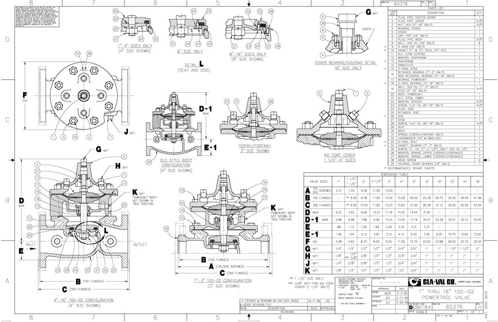
6 USEFUL INFORMATION OR HINTS 1. The approximate volume of liquid discharged from the chamber above the diaphragm when the valve moves from the fully closed positions to the fully open is as follows: VALVE SIZE 1/2" 3/4" 1" 1 1/4" 1 1/2" 2" 2 1/2" 3" 4" 6" 8' 10" 12" 14" 16" Fl. Oz Fl. Oz Fl. Oz Gal Gal Gal Gal Gal Gal Gal Gal Gal Gal Gal Gal. DISPLACEMENT.01 Liters.01 Liters.02 Liters.10 Liters.10 Liters.10 Liters.20 Liters.30 Liters.60 Liters 2.00 Liters 4.75 Liters 9.50 Liters Liters Liters Liters POWERTROL VALVE SIZES 1" - 3" ITEM PART DESCRIPTION 1 CENTER COVER PLUG 2 COVER PLUG 3 STUD NUT 7 PLUG, PIPE, BODY 10 * GASKET "O" RING 14 NAMEPLATE 15 * O-RING, STEM 16 RETAINER BEARING (1-3 ONLY) 19 BOLT, HEX HD. (1-3 ONLY) 20 POWER UNIT BODY 21 LOWER STEM NUT 22 SPACER WASHER 24 DISC GUIDE 25 DISC RETAINER 30 BODY 31 SPRING (100-02KH/100PAKH ONLY) 32 LOCK WASHER - SPRING 33 * SEAT O-RING 34 * GASKET BEARING GASKET (1-3" ONLY) 35 Screw Fil. HD. ( ) / BOLT HEX. (3 ) 36 UPPER WASHER SPRING (100PKCH) 37 LOWER WASHER SPRING (100PAKCH) 38 DRIVE SCREW * RECOMMENDED SPARE PARTS J NPT Model KH Seat & Disc Details
7 G NPT COVER INLET J J NPT NPT K 5 NPT H NPT OUTLET ITEM PART DESCRIPTION 1 CENTER COVER PLUG 2 COVER PLUG 3 STUD NUT 4 COVER BEARING 5 COVER 6 PIPE CAP (16" ONLY) 7 PLUG, PIPE, BODY 8 BOLT HEX HD (16" ONLY) 9 * O-RING (16" ONLY) 10 * GASKET "O" RING 11 UPPER STEM NUT 12 UPPER DlAPHRAGM WASHER 13 * DIAPHRAGM 14 NAMEPLATE 15 * O-RING, STEM 16 RETAINER BEARING (1-3 ONLY) RING RETAINER BEARING (4-16 ONLY) 17 POWER UNIT BEARING 18 * O-RING BEARING (4-16 ONLY) 19 BOLT, HEX HD. (1-3 ONLY) STUD (4-16 ONLY 20 POWER UNIT BODY 21 LOWER STEM NUT 22 SPACER WASHER 23 DISC GUIDE SCREW (6" - 16" ONLY) 24 DISC GUIDE 25 DISC RETAINER 26 * DISC 27 STEM 28 SEAT SCREW (8-16 ONLY) 29 SEAT 30 BODY 31 SPRING (100-02KH/100PAKH ONLY) 32 LOCK WASHER - SPRING 33 * SEAT O-RING 34 * GASKET BEARING GASKET (1-3" ONLY) 35 Screw Fil. HD. ( ) / BOLT HEX. (3 ) 36 UPPER WASHER SPRING (100PKCH) 37 LOWER WASHER SPRING (100PAKCH) 38 DRIVE SCREW 39 COVER BEARING HOUSING (16" ONLY) * RECOMMENDED SPARE PARTS CLA-VAL 1701 Placentia Ave Costa Mesa CA Phone: Fax: info@cla-val.com Copyright Cla-Val 2017 Printed in USA Specifications subject to change without notice. N (R-08/2017)
8
9 Cla-Val Product Identification How to Order Proper Identification For ordering repair kits, replacement parts, or for inquiries concerning valve operation, it is important to properly identify Cla-Val products already in service by including all nameplate data with your inquiry. Pertinent product data includes valve function, size, material, pressure rating, end details, type of pilot controls used and control adjustment ranges. Identification Plates For product identification, cast-in body markings are supplemented by identification plates as illustrated on this page. The plates, depending on type and size of product, are mounted in the most practical position. It is extremely important that these identification plates are not painted over, removed, or in any other way rendered illegible. INLET EINTRITT ENTREE ENTRADA SIZE & CAT STOCK CODE MFD. BY CLA-VAL NEWPORT BEACH, CALIF, U.S.A. This brass plate appears on valves sized 2 1 / 2" and larger and is located on the top of the inlet flange. INLET INLET These two brass plates appear on 3 / 8", 1 / 2", and 3 / 4" size valves and are located on the valve cover. RESERVOIR END This brass plate appears on altitude valves only and is found on top of the outlet flange. SIZE & CAT STOCK FLOW MFD. BY CLA-VAL NEWPORT BEACH, CALIF. U.S.A. CODE These two brass plates appear on threaded valves 1" through 3" size or flanged valves 1" through 2". It is located on only one side of the valve body. SPRING RANGE C SIZE & CAT STOCK SIZE & CAT STOCK CODE MFD. BY CLA-VAL NEWPORT BEACH, CALIF. U.S.A. MFD. BY CLA-VAL NEWPORT BEACH, CALIF. U.S.A. This tag is affixed to the cover of the pilot control valve. The adjustment range appears in the spring range section. This brass plate is used to identify pilot control valves. The adjustment range is stamped into the plate. C DO NOT REMOVE THIS VALVE HAS BEEN MODIFIED SINCE ORIGINAL SHIPMENT FROM FACTORY. WHEN ORDERING PARTS AND/ OR SERVICE SUPPLY DATA FROM THIS PLATE & ALL OTHER PLATES ON ORIGINAL VALVE. This aluminum plate is included in pilot system modification kits and is to be wired to the new pilot control system after installation. CAT. RP -4 REDUCED PRESSURE BACKFLOW PREVENTION DEVICE STK. SER. CLA-VAL NEWPORT BEACH, CA. This brass plate is used on our backflow prevention assemblies. It is located on the side of the Number Two check (2" through 10"). The serial number of the assembly is also stamped on the top of the inlet flange of the Number One check.
10 HOW TO ORDER Because of the vast number of possible configurations and combinations available, many valves and controls are not shown in published product and price lists. For ordering information, price and availability on product that are not listed, please contact your local Cla-Val office or our factory office located at: P. O. Box 1325 Newport Beach, California (949) FAX (949) LIMITED WARRANTY Automatic valves and controls as manufactured by Cla-Val are warranted for three years from date of shipment against manufacturing defects in material and workmanship that develop in the service for which they are designed, provided the products are installed and used in accordance with all applicable instructions and limitations issued by Cla-Val. Electronic components manufactured by Cla-Val are warranted for one year from the date of shipment. We will repair or replace defective material, free of charge, that is returned to our factory, transportation charges prepaid, if upon inspection, the material is found to have been defective at time of original shipment. This warranty is expressly conditioned on the purchaser s providing written notification to Cla-Val immediate upon discovery of the defect. Components used by Cla-Val but manufactured by others, are warranted only to the extent of that manufacturer s guarantee. This warranty shall not apply if the product has been altered or repaired by others, Cla-Val shall make no allowance or credit for such repairs or alterations unless authorized in writing by Cla-Val. SPECIFY WHEN ORDERING Model Number Valve Size Globe or Angle Pattern Threaded or Flanged Adjustment Range Body and Trim Materials (As Applicable) Optional Features Pressure Class UNLESS OTHERWISE SPECIFIED Globe or angle pattern are the same price Ductile iron body and bronze trim are standard X46 Flow Clean Strainer or X43 Y Strainer are included CK2 Isolation Valves are included in price on 4" and larger valve sizes (6" and larger on 600 Series) DISCLAIMER OF WARRANTIES AND LIMITATIONS OF LIABILITY The foregoing warranty is exclusive and in lieu of all other warranties and representations, whether expressed, implied, oral or written, including but not limited to any implied warranties or merchantability or fitness for a particular purpose. All such other warranties and representations are hereby cancelled. Cla-Val shall not be liable for any incidental or consequential loss, damage or expense arising directly or indirectly from the use of the product. Cla-Val shall not be liable for any damages or charges for labor or expense in making repairs or adjustments to the product. Cla-Val shall not be liable for any damages or charges sustained in the adaptation or use of its engineering data and services. No representative of Cla-Val may change any of the foregoing or assume any additional liability or responsibility in connection with the product. The liability of Cla-Val is limited to material replacements F.O.B. Newport Beach, California. TERMS OF SALE ACCEPTANCE OF ORDERS All orders are subject to acceptance by our main office at Newport Beach, California. CREDIT TERMS Credit terms are net thirty (30) days from date of invoice. PURCHASE ORDER FORMS Orders submitted on customer s own purchase order forms will be accepted only with the express understanding that no statements, clauses, or conditions contained in said order form will be binding on the Seller if they in any way modify the Seller s own terms and conditions of sales. PRODUCT CHANGES The right is reserved to make changes in pattern, design or materials when deemed necessary, without prior notice. PRICES All prices are F.O.B. Newport Beach, California unless expressly stated otherwise on our acknowledgement of the order. Prices are subject to change without notice. The prices at which any order is accepted are subject to adjustment to the Seller s price in effect at the time of shipment. Prices do not include sales, excise, municipal, state or any other Government taxes. Minimum order charge $ RESPONSIBILITY We will not be responsible for delays resulting from strikes, accidents, negligence of carriers, or other causes beyond our control. Also, we will not be liable for any unauthorized product alterations or charges accruing there from. RISK All goods are shipped at the risk of the purchaser after they have been delivered by us to the carrier. Claims for error, shortages, etc., must be made upon receipt of goods. EXPORT SHIPMENTS Export shipments are subject to an additional charge for export packing. RETURNED GOODS 1. Customers must obtain written approval from Cla-Val prior to returning any material. 2. Cla-Val reserves the right to refuse the return of any products. 3. Products more than six (6) months old cannot be returned for credit. 4. Specially produced, non-standard models cannot be returned for credit. 5. Rubber goods such as diaphragms, discs, o-rings, etc., cannot be returned for credit, unless as part of an unopened vacuum sealed repair kit which is less than six months old. 6. Goods authorized for return are subject to a 35% ($100 minimum) restocking charge and a service charge for inspection, reconditioning, replacement of rubber parts, retesting, repainting and repackaging as required. 7. Authorized returned goods must be packaged and shipped prepaid to Cla-Val, 1701 Placentia Avenue, Costa Mesa, California E-Product I.D. (R-3/2011) CLA-VAL PO Box 1325 Newport Beach CA Phone: Fax: CLA-VAL CANADA 4687 Christie Drive Beamsville, Ontario Canada L0R 1B4 Phone: Fax: COPYRIGHT CLA-VAL 2011 Printed in USA Specifications subject to change without notice. CLA-VAL EUROPE Chemin dés Mesanges 1 CH-1032 Romanel/ Lausanne, Switzerland Phone: Fax: Represented By:
11 INSTALLATION / OPERATION / MAINTENANCE MODEL REPAIR KITS Model Hytrol Main Valve BUNA-N MATERIAL RUBBER KIT REPAIR KIT REBUILD KIT STUD & NUT KIT STOCK STOCK STOCK STOCK 3/ K B J 1/ H F A H 3/ H F A H 1 Non-Guided F G K F D E J F 1 1/ D E J F 1 1/ D E J F A K H E 2 1/ J J G D G D D C E C C K K B B J D A A H B F K G K E J F H D H E E C G E Model Hytrol Main Valve BUNA-N MATERIAL RUBBER KIT REPAIR KIT REBUILD KIT STUD & NUT KIT STOCK STOCK STOCK STOCK A K H E G D D C E C C K K B B J D A A H B F K G K E J F K E J F Consult factory for larger sizes Rubber Kit Includes: Repair Kit Includes: Rebuild Kit Includes: Diaphragm, Disc, Spacer Washers Diaphragm, Disc, Spacer Washers, Epoxy Coated Disc Retainer, Epoxy Coated Diaphragm Washer, Protective Washer Diaphragm, Disc, Spacer Washers, Epoxy Coated Disc Retainer, Epoxy Coated Diaphragm Washer, Protective Washer, Stainless Steel Bolts & Washers (6" & Below), Stainless Steel Studs, Nuts, & Washers (8" & Above), Stem, Stem Nut, Disc Guide Stud & Nut Kit Includes: Stainless Steel Bolts & Washers (6" & Below), Stainless Steel Studs, Nuts, & Washers (8" & Above)
12 Repair Kits for / Powertrol and / Powercheck Main Valves For: Powertrol and Powercheck Main Valves 150 Pressure Class Only Includes: Diaphragm, Disc (or Disc Assembly) and O-rings and full set of spare Spacer Washers. Valve Kit Stock Number Valve Kit Stock Number Size Size & & H J N/A 1 2 & F G J D E G & B C E J G C H 99116G B H Repair Kits for / Hy-Check Main Valves For: Hy-Check Main Valves 150 Pressure Class Only Includes: Diaphragm, Disc and O-Rings and full set of spare Spacer Washers. Repair Kits for Pilot Control Valves (In Standard Materials Only) Includes: Diaphragm, Disc (or Disc Assembly), O-Rings, Gaskets or spare Screws as appropriate. Repair Assemblies (In Standard Materials Only) CLA-VAL Larger Sizes: Consult Factory. Valve Kit Stock Number Valve Kit Stock Number Size Size B N/A H J A B G N/A K A F H J K 20 N/A F 24 N/A F Larger Sizes: Consult Factory. BUNA-N (Standard Material) VITON (For KB Controls) Pilot Control Kit Stock Number Pilot Control Kit Stock Number Pilot Control Kit Stock Number CDB C CFM E CDB-KB A CDB H CRA (w/bucking spring) D CRA-KB N/A CDB F CRD (w/bucking spring) B CRD-KB (w/bucking spring) J CDB K CRD (no bucking spring) K CRL-KB J CDH D CRD K CDHS-2BKB E CDHS A CRD G CDHS-2FKB C CDHS-2B H CRL (55F, 55L) A CDHS-18KB (no bucking spring) G CDHS-2F E CRL60/55L G 102C-KB D CDHS-3C-A K CRL60/55L60 1" H CDHS-8A A CRL-4A 43413E CDHS K CRL-5 (55B) 65755B CDS G CRL-5A (55G) 20666E CDS A CRL C CDS A Universal CRL K CDS-6A C CV F CFCM-M C X105L (O-ring) 00951E CFM E 102B F Buna-N CFM K 102C F CRD Disc Ret. (Solid) C5256H CFM-7A K 102C F CRD Disc Ret. (Spring) C5255K Control Description Stock Number CF1-C1 Pilot Assembly Only 89541H CF1-Cl Complete Float Control less Ball and Rod 89016A CFC2-C1 Disc, Distributor and Seals E CSM 11-A2-2 Mechanical Parts Assembly 97544B CSM 11-A2-2 Pilot Assembly Only 18053K 33A 1 Complete Internal Assembly and Seal B 33A 2 Complete Internal Assembly and Seal J When ordering, please give complete nameplate data of the valve and/or control being repaired. MINIMUM ORDER CHARGE APPLIES 1701 Placentia Ave Costa Mesa CA Phone: Fax: info@cla-val.com Copyright Cla-Val 2018 Printed in USA Specifications subject to change without notice. N-RK (R-08/2018)
4 - Way Control 4 - Way Control 4 - Way Control with lock
 INSTALLATION / OPERATION / MAINTENANCE 1. DESCRIPTION MODEL 0-02 (Full Internal Port) Powertrol Valve This manual contains information for installation, operation and maintenance of the Cla-Val Co. 0-02
SS Hytrol Valve MODEL. Principle of Operation
 590-01 MODEL 100-44 (Reduced Internal Port) 316SS Hytrol Valve All 316 Stainless Steel Reduced Cavitation Design Drip-Tight, Positive Sealing Action Service Without Removal From Line Every Valve Factory
Three Way Pilot Control
 Description The CIa-VaI Model 00-0 Hytrol Valve is a main valve for CIa-VaI Automatic Control Valves. It is a hydraulically operated, diaphragm-actuated, globe or angle pattern valve. This valve consists
INSTALLATION / OPERATION / MAINTENANCE MODEL SERVICE AND MAINTENANCE OF 600 SERIES VALVES UNDERSTANDING THE 600 SERIES VALVES
 INSTALLATION / OPERATION / MAINTENANCE MODEL 100-20 (Reduced Internal Port) 600 Series Hytrol Valve SERVICE AND MAINTENANCE OF 600 SERIES VALVES The 600 series main valves have only one part -the body-
50B-5KG. Pump Suction Control Valve MODEL. Specifications. Typical Installation. Adjustable Opening Speed For Pump Suction Protection
 0B-KG MODEL 0B-KG Pump Suction Control Valve Adjustable Opening Speed For Pump Suction Protection Pilot Control Provides Wide Flow Range With Minimal Pressure Variations Controlled Closing For System
50B-5KG/2050B-5KG. Distributed By: M&M Control Service, Inc. Phone: Fax:
 0B-KG/200B-KG Distributed By: M&M Control Service, Inc. Phone: 00-7-003 Fax: 7-3-077 Email: sales@mmcontrol.com MODEL 0B-KG Pump Suction Control Valve Adjustable Opening Speed For Pump Suction Protection
 0-0/0-0 Description The CIa-VaI Model 00-0 Hytrol Valve is a main valve for CIa-VaI Automatic Control Valves. It is a hydraulically operated, diaphragm-actuated, globe or angle pattern valve. This
81-01/ Check Valve
 8-0 MODEL INSTALLATION / OPERATION / MAINTENANCE 8-0/68-0 Check Valve INTRODUCTION The Cla-Val Model 8-0/68-0 Check Valve is an automatic valve designed to close drip tight when outlet pressure exceeds
Series Roll Seal
 790-63 INSTALLATION / OPERATION / MAINTENANCE SERIES 00-4 700 Series Roll Seal DESCRIPTION The Cla-Val Model 00-4 Roll Seal valve is a hydraulically operated valve used to control liquid flow by means
Cla-Val. Service Training Manual. Simple solutions plus learning with a purpose
 Cla-Val Service Training Manual Simple solutions plus learning with a purpose 5 Application Series Section General Identify What Valve You Have 5-1 Rate of Flow 40 Series 5-2 Pressure Relief 50 Series
90G-21 90A-21 Fire Protection Pressure Reducing Valve
 90-21 TM Fire Products TM MODELS 90G-21 90A-21 Fire Protection Pressure Reducing Valve 90-21 Listed Fire Protection Valve 90-21 Listed Grooved End Fire Protection Valve U.L. Listed, C Listed, MEA Approved
INSTALLATION AND MAINTENANCE INSTRUCTIONS 3-WAY SOLENOID VALVES, NORMALLY OPEN NORMALLY CLOSED AND UNIVERSAL CONSTRUCTION
 134-05 DESCRIPTION Bulletin 8320 is a small 3-way solenoid operated valve with all three pipe connections located in the body. The bodies are of brass or stainless steel construction. Standard valves
Typical Applications. Installation
 124-01/624-01 Schematic Diagram Item Description 1 Hytrol (Main Valve) 2 CF1-C1 Float Control (Sizes 1/2"-6") 124-01 (Full Internal Port) MODELS (Sizes 3"-8") 624-01 (Reduced Internal Port) Float Valve
79488 J Model 50-01/650-01
 50-01/650-01 TM 79488 J Model 50-01/650-01 Pressure Relief Valve (Equipped with Closing Speed Control) 11-30-78 11-30-78 11-30-78 JD CH WAL P1 B1 D1 REMOTE SENSING F INLET NOT FURNISHED BY CLA-VAL CO.
Float Valve MODEL. Schematic Diagram. Optional Features. Typical Applications
 129-01/629-01 Schematic Diagram Item Description 1 Hytrol (Main Valve) 2 X47A Ejector 3 Bell Reducer 4 CFM2 Float Control MODEL Float Valve Accurate and Repeatable Level Control Proportional Flow Reliable
 210-16/610-16 Description The CIa-VaI Model 100-01 Hytrol Valve is a main valve for CIa-VaI Automatic Control Valves. It is a hydraulically operated, diaphragm-actuated, globe or angle pattern valve.
Distributed By: M&M Control Service, Inc /650-90
 50-90/650-90 Distributed By: M&M Control Service, Inc. Phone: 800-876-0036 Fax: 847-356-0747 Email: sales@mmcontrol.com Description The CIa-VaI Model 100-01 Hytrol Valve is a main valve for CIa-VaI
Repair Kits & Parts Lists
 Table of Contents Repair Kits & Parts Lists Main Valve + Pilot Repair Kits 0-01/0-01.... 3 50-01/50-01.... 0/1 Series... 5 Main Valve Repair Kits 0-01.... Pilot Control Repair Kits CDB.... CDB-.... CDH-2....
Distributed By: M&M Control Service, Inc
 90-21 U L INSTALLATION / OPERATION / MAINTENANCE MODEL 90-21 Listed Pressure Reducing Valve The Cla-Val 90-21 Pressure Reducing Valve is a pilot-operated regulator, capable of holding downstream pressure
Three Way Pilot Control
 390-07/3690-07 Description The CIa-VaI Model 100-01 Hytrol Valve is a main valve for CIa-VaI Automatic Control Valves. It is a hydraulically operated, diaphragm-actuated, globe or angle pattern valve.
Loading. Inlet ROLL SEAL. Outlet
 750-0 Outlet Inlet Loading ROLL SEAL MODEL Compact Design, Proven Reliable Light Weight Materials High Pressure Rating Availability Easy Installation and Maintenance 00-4 700 SERIES ROLL SEAL The Cla-Val
124-01/ Distributed By: M&M Control Service, INC. Phone: Fax:
 124-01/624-01 Distributed By: M&M Control Service, INC. Phone: 800-876-006 Fax: 847-56-0747 Email: Sales@mmcontrol. INSTALLATION / OPERATION / MAINTENANCE MODEL 124-01 624-01 Float Valve Description The
Electronic Control Valves
 MODEL 131 Series (Full Internal Port) 631 Series (Reduced Internal Port) Electronic Control Valves Model 131-01/631-01 Simple Proven Design Quality Solenoid Pilot Controls Ideal For SCADA Systems Multi-Function
Distributed By: M&M Control Service, Inc KO/650-01KO
 50-01KO/650-01KO INTRODUCTION The Cla-Val 50-01/650-01 is an automatic control valve designed to maintain constant upstream pressure to close limits. It is a hydraulically operated, pilot controlled, modulating
Pressure Reducing Valve with Low Flow By-Pass MODEL. Schematic Diagram. Optional Features. Typical Applications
 90-99 MODEL 90-99 (Full Internal Port) Pressure Reducing Valve with Low Flow By-Pass Schematic Diagram Item Description 1 90-01 Pressure Reducing Valve 1-1 Hytrol (Main Valve) 1-2 X58C Restriction Tube
APCO CRF-100A RUBBER FLAPPER SWING CHECK VALVES
 APCO CRF-100A RUBBER FLAPPER SWING CHECK VALVES Instruction D12043 June 2016 DeZURIK Instructions These instructions provide installation, operation and maintenance information for APCO CRF-100A Rubber
2-12 Grooved End Dual Disc Check Valve. Operation, Maintenance and Installation Manual
 Manual No. DDCV-OM4-1 2-12 Grooved End Dual Disc Check Valve Operation, Maintenance and Installation Manual INTRODUCTION... 1 RECEIVING AND STORAGE... 1 DESCRIPTION OF OPERATION... 1 INSTALLATION... 2
ALTITUDE CONTROL VALVES FOR ONE WAY FLOW
 PROJECT NAME LOCATION ALTITUDE CONTROL VALVES FOR ONE WAY FLOW INTRODUCTION This specification covers the design, manufacture, and testing of 2 in. (50 mm) through 36 in. (900 mm) Control Valves PART 1
Wafer and Globe Style Silent Check Valve. Operation, Maintenance and Installation Manual
 Manual No. SCV-OM1-4 Wafer and Globe Style Silent Check Valve Operation, Maintenance and Installation Manual INTRODUCTION... 1 RECEIVING AND STORAGE... 1 DESCRIPTION OF OPERATION... 1 INSTALLATION... 2
PRESSURE RELIEF / SUSTAINING CONTROL VALVES
 PROJECT NAME LOCATION PRESSURE RELIEF / SUSTAINING CONTROL VALVES INTRODUCTION This specification covers the design, manufacture, and testing of 1 in. (25 mm) through 36 in. (900 mm) Control Valves PART
Swing-Flex Check Valve
 Manual No. SFCV-OM1-14 Swing-Flex Check Valve Operation, Maintenance and Installation Manual INTRODUCTION.. 1 RECEIVING AND STORAGE. 1 DESCRIPTION OF OPERATION.. 1 INSTALLATION 2 VALVE CONSTRUCTION.. 2
MODEL 106/206-PG POWER OPERATED GLOBE VALVE Sizes 1/2" to 8" (106-PG) 3" to 10" (206-PG) Installation, Operating and Maintenance Instructions
 3 to 10 (206-PG) Installation, Operating and Maintenance Instructions") MODEL 106/206-PG POWER OPERATED GLOBE VALVE Sizes 1/2" to 8" (106-PG) 3" to 10" (206-PG) Installation, Operating and Maintenance Instructions DESCRIPTION: This valve is the basic component used for most
MODEL 106/206-PG POWER OPERATED GLOBE VALVE Sizes 1/2" to 8" (106-PG) 3" to 10" (206-PG) Installation, Operating and Maintenance Instructions DESCRIPTION: This valve is the basic component used for most
FLOAT CONTROL VALVES
 PROJECT NAME LOCATION FLOAT CONTROL VALVES INTRODUCTION This specification covers the design, manufacture, and testing of 8 in. (200 mm) through 36 in. (900 mm) Control Valves PART 1 - GENERAL 1. Standard
Val-Matic 1/2-3 Well Service Air Valve With Dual Port Throttling Device
 Manual No. WSAV-OM1-2 Val-Matic 1/2-3 Well Service Air Valve With Dual Port Throttling Device Operation, Maintenance and Installation Manual INTRODUCTION... 1 RECEIVING AND STORAGE... 1 DESCRIPTION OF
Swing-Flex Check Valve
 Manual No. SFCV-OM1-11 Swing-Flex Check Valve Operation, Maintenance and Installation Manual INTRODUCTION 1 RECEIVING AND STORAGE 1 DESCRIPTION OF OPERATION 1 INSTALLATION 2 VALVE CONSTRUCTION 2 MAINTENANCE
TITAN FLOW CONTROL, INC.
 PREFACE: TITAN FLOW This manual contains information concerning the installation, operation, and maintenance of Titan Flow Control (Titan FCI)Full Body Swing Check Valves. To ensure efficient and safe
Model GP Triplex Ceramic Plunger Pump Operating Instructions/ Manual
 Model GP6145-3100 Triplex Ceramic Plunger Pump Operating Instructions/ Manual Contents: Installation Instructions: page 2 Pump Specifications: page 3 Exploded View: page 4 Parts List / Kits: page 5 Repair
Cla-Val. Service Training Manual. Simple solutions plus learning with a purpose
 Cla-Val Service Training Manual Simple solutions plus learning with a purpose Section Model Pilot Controls Section CRD Pressure Reducing -1 CRA Reducing Pilot with -1 Remote Sensing CRL Relief Pilot (55F
INTRODUCTION INSTALLATION
 INTRODUCTION INSTALLATION, OPERATION & MAINTENANCE INSTRUCTIONS This instruction manual includes installation, operation and maintenance information for the figure G73 gear operator. The figure G73 is
PRESSURE REDUCING CONTROL VALVES
 PROJECT NAME LOCATION PRESSURE REDUCING CONTROL VALVES INTRODUCTION This specification covers the design, manufacture, and testing of 1 in. (25 mm) through 36 in. (900 mm) Control Valves PART 1 - GENERAL
Model BP6150. Triplex Ceramic Plunger Pump Operating Instructions/ Manual
 Model BP6150 Triplex Ceramic Plunger Pump Operating Instructions/ Manual Contents: Installation Instructions: page 2 Pump Specs: page 3 Exploded View: page 4 Parts List / Kits Torque Specifications: page
14 and Larger Wafer and Lug Style Dual Disc Check Valve. Operation, Maintenance and Installation Manual
 Manual No. DDCV-OM2-2 14 and Larger Wafer and Lug Style Dual Disc Check Valve Operation, Maintenance and Installation Manual INTRODUCTION... 1 RECEIVING AND STORAGE... 1 DESCRIPTION OF OPERATION... 1 INSTALLATION...
TITAN FLOW CONTROL, INC.
 PREFACE: This manual contains information concerning the installation, operation, and maintenance of Titan Flow Control (Titan FCI) Wafer Style, Dual Plate Check Valves. To ensure efficient and safe operation
PRESSURE RELIEF / SURGE ANTICIPATOR CONTROL VALVE
 PROJECT NAME LOCATION PRESSURE RELIEF / SURGE ANTICIPATOR CONTROL VALVE INTRODUCTION This specification covers the design, manufacture, and testing of 2-1/2 in. (65 mm) through 18 in. (450 mm) Control
DeZURIK 2-24 (50-600mm) KGN-RSB BI-DIRECTIONAL CAST STAINLESS STEEL KNIFE GATE VALVES
 KGN-RSB BI-DIRECTIONAL CAST STAINLESS STEEL KNIFE GATE VALVES") 2-24 (50-600mm) KGN-RSB BI-DIRECTIONAL CAST STAINLESS STEEL KNIFE GATE VALVES Instruction D11023 October 2016 Instructions These instructions provide information about KGN-RSB Knife Gate Valves. They are
2-24 (50-600mm) KGN-RSB BI-DIRECTIONAL CAST STAINLESS STEEL KNIFE GATE VALVES Instruction D11023 October 2016 Instructions These instructions provide information about KGN-RSB Knife Gate Valves. They are
COMBINATION PRESSURE REDUCING AND SOLENOID SHUTOFF CONTROL VALVES 2.01 COMBINATION RESSURE REDUCING AND SOLENOID SHUTOFF CONTROL VALVE
 PROJECT NAME LOCATION COMBINATION PRESSURE REDUCING AND SOLENOID SHUTOFF CONTROL VALVES INTRODUCTION This specification covers the design, manufacture, and testing of 1 in. (25 mm) through 36 in. (900
APCO CSV-1600 SURGE CHECK VALVE
 APCO CSV-1600 SURGE CHECK VALVE Instruction D12022 January 2013 Instructions These instructions provide installation, operation and maintenance information for APCO CSV-1600 Surge Check Valves. They are
Val-Matic 1-4 Combination Air Valve (Single Housing Type)
") Manual No. ARCO-OM1-3 Val-Matic 1-4 Combination Air Valve (Single Housing Type) Operation, Maintenance and Installation Manual INTRODUCTION... 1 RECEIVING AND STORAGE... 1 DESCRIPTION OF OPERATION... 1
Manual No. ARCO-OM1-3 Val-Matic 1-4 Combination Air Valve (Single Housing Type) Operation, Maintenance and Installation Manual INTRODUCTION... 1 RECEIVING AND STORAGE... 1 DESCRIPTION OF OPERATION... 1
MODEL. Schematic Diagram. Optional Features. Typical Applications
 9-0/9-0 MODEL 9-0 (Full Internal Port) 9-0 (Reduced Internal Port) Electronic Actuated Rate of Flow and Pressure Reducing Valve Schematic Diagram Item Description Hytrol (Main Valve) X8C Restriction
Nor East. Instructions Safety Messages. Inspection. Parts. DeZURIK Service. Type 05 Pneumatic Actuator Used With Globe Valves
 Instructions Safety Messages These instructions are intended for personnel who are responsible for installation, operation and maintenance of your DeZURIK Actuator. All safety messages in the instructions
Val-Matic 1-4 Combination Air Valve (Single Housing Type)
") Manual No. ARCO-OM1-2 Val-Matic 1-4 Combination Air Valve (Single Housing Type) Operation, Maintenance and Installation Manual INTRODUCTION... 1 RECEIVING AND STORAGE... 1 DESCRIPTION OF OPERATION... 1
Manual No. ARCO-OM1-2 Val-Matic 1-4 Combination Air Valve (Single Housing Type) Operation, Maintenance and Installation Manual INTRODUCTION... 1 RECEIVING AND STORAGE... 1 DESCRIPTION OF OPERATION... 1
4000SS. For other repair kits and service parts, send for Ames Repair Parts Price List, PL-A-RP-BPD.
 Series 4000SS RP/IS-A-4000SS 4000SS Reduced Pressure Zone Assemblies Sizes: 8" 10" (200 250mm) Installation Service Repair Kits Maintenance For other repair kits and service parts, send for Ames Repair
 43-01/643-01 Description The CIa-VaI Model 100-01 Hytrol Valve is a main valve for CIa-VaI Automatic Control Valves. It is a hydraulically operated, diaphragm-actuated, globe or angle pattern valve.
APCO ASR-400/450 SEWAGE AIR RELEASE VALVES
 APCO ASR-400/450 SEWAGE AIR RELEASE VALVES Instruction D12005 December 2012 Instructions These instructions provide installation, operation and maintenance information for the APCO ASR- 400/450 Sewage
50-01 (Full Internal Port) (Reduced Internal Port) Pressure Relief. & Pressure Sustaining Valve MODEL
 (Reduced Internal Port) Pressure Relief. & Pressure Sustaining Valve MODEL") 50-01 650-01 & 1 Hytrol (Main ) 2 X42N-2 Strainer & Needle 3 CRL Control Accurate Pressure Control Optional Check Feature Fast Opening to Maintain Line Pressure Slow Closing to Prevents s Completely Automatic
50-01 650-01 & 1 Hytrol (Main ) 2 X42N-2 Strainer & Needle 3 CRL Control Accurate Pressure Control Optional Check Feature Fast Opening to Maintain Line Pressure Slow Closing to Prevents s Completely Automatic
SOLENOID CONTROL VALVE
 PROJECT NAME LOCATION SOLENOID CONTROL VALVE INTRODUCTION This specification covers the design, manufacture, and testing of 4 in. (100 mm) through 36 in. (900 mm) Control Valves PART 1 - GENERAL 1. Standard
QTY ADDED TO CATALOG NUMBER
 50B-KG/050B-KG TLC --9 JB -7-97 BF 0-8- MS 9-- TYPE OF VALVE AND MAIN FEATURES CVCL NOT FURNISHED BY CLA-VAL CO. DIST. CODE 050 CATALOG NO. 50B-KG (GLOBE) 050B-KG (ANGLE) PRESSURE RELIEF VALVE FACTORY
Model 585 Swing Check Valve
 INSTALLATION / OPERATION / MAINTENANCE Model 585 Swing Check Valve Swing Check Valve with Lever and Spring, Lever and Weight, and/or Side Mounted Air Cushion INTRODUCTION RECEIVING AND STORAGE VALVE CONSTRUC
P SERIES PUMPS. 18mm Versions Nickle-Aluminum Bronze Models: P , P , P , P , P , P , P
 P200-3100 SERIES PUMPS 18mm Versions Nickle-Aluminum Bronze Models: P217-3100, P218-3100, P219-3100, P220-3100, P221-3100, P227-3100, P230-3100 Triplex Ceramic Plunger Pump Operating Instructions/ Repair
MODULATING FLOAT CONTROL VALVE
 PROJECT NAME LOCATION MODULATING FLOAT CONTROL VALVE INTRODUCTION This specification covers the design, manufacture, and testing of 2 in. (50 mm) through 36 in. (900 mm) Control Valves PART 1 - GENERAL
GA Industries, LLC 9025 Marshall Road Cranberry Township, PA USA Telephone (724) Fax (724)
 Fax (724)") INSTALLATION, OPERATION AND MAINTENANCE MANUAL LUDLOW SERIES FIGURE 350-W 3 to 30 Lever & Weight Air-Cushioned Swing Check Valves TABLE OF CONTENTS Introduction. 1 Description of Operation... 1 Receiving
INSTALLATION, OPERATION AND MAINTENANCE MANUAL LUDLOW SERIES FIGURE 350-W 3 to 30 Lever & Weight Air-Cushioned Swing Check Valves TABLE OF CONTENTS Introduction. 1 Description of Operation... 1 Receiving
PENBERTHY MODELS GL AND GH GAS OPERATED JET PUMPS INSTALLATION, OPERATION AND MAINTENANCE INSTRUCTIONS
 Before installation, these instructions must be read carefully and understood. PRODUCT WARRANTY Emerson warrants its Penberthy products as designed and manufactured to be free of defects in the material
DeZURIK KUL KNIFE GATE VALVES
 KUL KNIFE GATE VALVES Instruction D11025 September 2013 Instructions These instructions are intended for personnel who are responsible for the installation, operation and maintenance of your KUL knife
MULTIPOSITION AIR CYLINDER
 MULTIPOSITION AIR CYLINDER CAST ALUMINUM FOUR-POSITION - ALL AIR SERVICE INFORMATION MOUNTING! Devices should be mounted and positioned in such a manner that they cannot be accidentally operated. INSTALLATION
TK08 TUNING KIT TECHNICAL MANUAL FOR 16/26/27/28 SERIES SHOCKS Revised 6/17/14
 Tech Line: (952) 985-5675 Fax (952) 985-5679 21730 Hanover Ave. Lakeville, MN 55044 www.qa1.net www.facebook.com/qa1motorsports TK08 TUNING KIT TECHNICAL MANUAL CONTENTS UNDER PRESSURE! USE EXTREME CAUTION
Pneumatic Cylinder 14 Bore X 22 Stroke Part No. R (Formerly P )
") Pneumatic Cylinder 14 Bore X 22 Stroke Part No. R434001268 (Formerly P -193419-00003) Service Information INSTALLATION Before installing this cylinder, all air lines in the system should be blown clean
Pneumatic Cylinder 14 Bore X 22 Stroke Part No. R434001268 (Formerly P -193419-00003) Service Information INSTALLATION Before installing this cylinder, all air lines in the system should be blown clean
TK08 TUNING KIT TECHNICAL MANUAL FOR 16/26/27/28 SERIES SHOCKS Revised 6/25/14 Tech Line: (952) Fax (952)
 Fax (952)") Tech Line: (952) 985-5675 Fax (952) 985-5679 21730 Hanover Ave. Lakeville, MN 55044 www.qa1.net www.facebook.com/qa1motorsports TK08 TUNING KIT TECHNICAL MANUAL CONTENTS UNDER PRESSURE! USE EXTREME CAUTION
Tech Line: (952) 985-5675 Fax (952) 985-5679 21730 Hanover Ave. Lakeville, MN 55044 www.qa1.net www.facebook.com/qa1motorsports TK08 TUNING KIT TECHNICAL MANUAL CONTENTS UNDER PRESSURE! USE EXTREME CAUTION
CUSTOM COMBINATION AIR VALVE
 INSTALLATION / OPERATION / MAINTENANCE CUSTOM COMBINATION AIR VALVE INTRODUCTION This manual will provide you with the information to properly install and maintain this valve to ensure a long service life.
Watts Series CSM-91. Grooved/Flanged Flow Measurement/Balancing Valves. Installation and Operating Instructions. Table of Contents. 1.
 Watts Series CSM-9 Grooved/Flanged Flow Measurement/Balancing Valves Installation and Operating Instructions IS-CSM-9 Table of Contents Item Description Page. Installation of Valve Angle Design 2. Installation
Three Way Pilot Control
 136-03/636-03 Description The CIa-VaI Model 100-01 Hytrol Valve is a main valve for CIa-VaI Automatic Control Valves. It is a hydraulically operated, diaphragm-actuated, globe or angle pattern valve.
½"-3" Air/Vacuum Valve Models 100S to 103S
 Manual No. A/VV-OM1-4 ½"-3" Air/Vacuum Valve Models 100S to 103S Operation, Maintenance and Installation Manual INTRODUCTION... 1 RECEIVING AND STORAGE... 1 DESCRIPTION OF OPERATION... 1 INSTALLATION...
Val-Matic 4-20 Air/Vacuum Valve
 Manual No. A/VV-OM2-4 Val-Matic 4-20 Air/Vacuum Valve Operation, Maintenance and Installation Manual INTRODUCTION... 1 RECEIVING AND STORAGE... 1 DESCRIPTION OF OPERATION... 1 INSTALLATION... 2 VALVE CONSTRUCTION...
Operating & Maintenance Manual For Steam Conditioning Valve
 For Steam Conditioning Valve 1 Table of Contents 1.0 Introduction 3 2.0 Product description 3 3.0 Safety Instruction 4 4.0 Installation and Commissioning 5 5.0 Valve Disassembly 6 6.0 Maintenance 6 7.0
AVK SERIES 41 SWING CHECK VALVE FIELD MAINTENANCE AND INSTRUCTION MANUAL FOR SWING CHECK VALVES 3" - 12"
 AMERICAN AVK COMPANY AVK SERIES 41 SWING CHECK VALVE FIELD MAINTENANCE AND INSTRUCTION MANUAL FOR SWING CHECK VALVES 3" - 12" TABLE OF CONTENTS EXPLODED ASSEMBLY / PARTS LIST INTRODUCTION / DESCRIPTION
Full View Flow Indicator
 Full View Flow Indicator Threaded and Flanged Process Connection Installation / Operation / Maintenance Manual P.O. Box 1116 Twinsburg, OH 44087 Phone: 330/405-3040 Fax: 330/405-3070 E-mail: view@ljstar.com
IMPORTANT OPERATING CONDITIONS. Failure to comply with any of these conditions invalidates the warranty. STANDARD CONFIGURATIONS
 X-SERIES TRIPLEX CERAMIC PLUNGER PUMPS OPERATING MANUAL MODELS X8 X10 X20 IMPORTANT OPERATING CONDITIONS Failure to comply with any of these conditions invalidates the warranty. Lubrication - Prior to
Pneumatic Cylinder 14 Bore X 21 Stroke Part No. P Replaces Part No. P
 Pneumatic Cylinder 14 Bore X 21 Stroke Part No. P -322908-00000 Replaces Part No. P-191067-00000 Service Information WARNING: INSTALLATION AND MOUNTING The user of these devices must conform to all applicable
TYPE S RELAY VALVE (Volume booster) Service Manual
 Service Manual") TYPE S RELAY VALVE (Volume booster) Service Manual The Type "S" Relay Valve is a pilot operated, 3-way, pneumatic pressure control valve with open exhaust. This large capacity valve receives pressure signals
TYPE S RELAY VALVE (Volume booster) Service Manual The Type "S" Relay Valve is a pilot operated, 3-way, pneumatic pressure control valve with open exhaust. This large capacity valve receives pressure signals
AVK SERIES 41 SWING CHECK VALVE FIELD MAINTENANCE AND INSTRUCTION MANUAL FOR SWING CHECK VALVES 3" - 12"
 AMERICAN AVK COMPANY AVK SERIES 41 SWING CHECK VALVE FIELD MAINTENANCE AND INSTRUCTION MANUAL FOR SWING CHECK VALVES 3" - 12" TABLE OF CONTENTS EXPLODED ASSEMBLY / PARTS LIST INTRODUCTION / DESCRIPTION
Series 867 Reduced Pressure Zone Assemblies
 RP/IS-F-867 INSTALLATION INSTRUCTIONS Series 867 Reduced Pressure Zone Assemblies 2 1 2" 3" (65 80mm) INDEX 867-NRS Installation Instructions....................................... 2-3 Service, Repair
THIS WARRANTY IS IN LIEU
 Installation, Operation, Maintenance and Parts Manual for Backflow Prevention Assemblies Double Check Valve Assembly Series 2000DCA 4" 10" Double Check Detector Assembly Series 3000DCDC 4" 10" Reduced
Booster Pump Control Valve
 MODEL 60-7 (Full Internal Port) 660-7 (Reduced Internal Port) ooster Pump Control Valve Simple Hydraulic Operation Low Head Loss Horizontal or Vertical Mounting uilt-in Check Valve Proven Reliable Design
Models GP5132, GP5136, GP5142 & GP5145. Triplex Ceramic Plunger Pump Operating Instructions / Manual
 Models GP5132, GP5136, GP5142 & GP5145 Triplex Ceramic Plunger Pump Operating Instructions / Manual Updated 07/14 Contents: Installation Instructions: page 2 Pump Specifications: page 3 Exploded View:
Air Operated Double Diaphragm Pump. M-Pump ½ Metallic Non Metallic Pump INSTALLATION, OPERATION & MAINTENANCE MANUAL
 Air Operated Double Diaphragm Pump M-Pump ½ Metallic Non Metallic Pump INSTALLATION, OPERATION & MAINTENANCE MANUAL 0.5 I.O.M rev 05. 12/2015 INDEX Title Section Introduction.1 Safety.2 Warranty, General
582 Series. Instruction Manual. Two-Door Wafer Check Valve N-582 (R-08/2016)
") 582 Series Two-Door Wafer Check Valve Instruction Manual N-582 (R-08/2016) Instructions These instructions provide installation, operation and maintenance information for Cla-Val 582 Series. They are for
582 Series Two-Door Wafer Check Valve Instruction Manual N-582 (R-08/2016) Instructions These instructions provide installation, operation and maintenance information for Cla-Val 582 Series. They are for
CONTENTS. VIKING PUMP, INC. A Unit of IDEX Corporation Cedar Falls, IA USA SECTION TSM 710.1
 TECHNICAL SERVICE MANUAL industrial heavy duty motor speed pumps SERIES 4076 AND 4176 SIZES hle, ate and ale SECTION TSM 710.1 PAGE 1 of 8 ISSUE B CONTENTS Introduction....................... 1 Safety
Model LP200, LP250 & LP250W-MT
 Triplex Ceramic Plunger Pump Operating Instructions/ Repair and Service Manual Model LP200, LP250 & LP250W-MT Updated 5/02 Contents: Installation Instructions: page 2 LP200 Specifications: page 3 Exploded
Colt Series C400, C500
 Colt Series C400, C500 RP/IS-A-C400/C500 C400 OSY Reduced Pressure Zone Assemblies Reduced Pressure Detector Assemblies Sizes: 2 1 2" 10" (65 250mm) Installation Service Repair Kits Maintenance For other
Series 957, 957N, 957Z, 957RPDA, 957NRPDA, 957ZRPDA
 Series 957, 957N, 957Z, 957RPDA, 957NRPDA, 957ZRPDA Reduced Pressure Zone Assemblies Reduced Pressure Detector Assemblies Sizes: 2 1 2" 10" (65 250mm) Installation Service Repair Kits Maintenance RP/IS-957/957RPDA
Tri-Clover Manual and Air Actuated Fractional Valves
 FVSM-99 Tri-Clover Manual and Air Actuated Fractional Valves Series 650 655 660 CONTENTS Thank you for purchasing an Alfa Laval Product! This manual contains disassembly and assembly instructions, maintenance
Positive Displacement Pump
 www.conairgroup.com U S E R G U I D E UGC028-1105 Positive Displacement Pump Models PD 3. 5, 7.5, 10, 15 and 25 Corporate Office: 724.584.5500 l Instant Access 24/7 (Parts and Service): 800.458.1960 l
DeZURIK 2-24 (50-600mm) KGC ES or HD KNIFE GATE VALVES
 KGC ES or HD KNIFE GATE VALVES") 2-24 (50-600mm) KGC ES or HD KNIFE GATE VALVES Instruction D10411 March 2017 Instructions These instructions are intended for personnel who are responsible for the installation, operation and maintenance
2-24 (50-600mm) KGC ES or HD KNIFE GATE VALVES Instruction D10411 March 2017 Instructions These instructions are intended for personnel who are responsible for the installation, operation and maintenance
I & M 8000 Series. Ideal Installation Schematic. Preferred Installation. Trouble Shooting
 I & M 8000 Series 3170 Wasson Road Cincinnati, OH 45209 USA Phone 513-533-5600 Fax 513-871-0105 lowflow@richardsind.com www.lowflowvalve.com Installation & Maintenance Instructions for 8000 Series Low
Crispin Valves Operating Guide. Crispin
 Crispin Valves Operating Guide Crispin Since 1905 Crispin Multiplex Manufacturing Co. 600 Fowler Avenue Berwick, PA 18603 1-800-AIR-VALV T: (570) 752-4524 F: (570) 752-4962 www.crispinvalve.com sales@crispinvalve.com
Wastewater Combination Air Valve. Operation, Maintenance and Installation Manual
 Manual No. WCAV-OM1-1 Wastewater Combination Air Valve Operation, Maintenance and Installation Manual INTRODUCTION... 2 RECEIVING AND STORAGE... 2 DESCRIPTION OF OPERATION... 2 INSTALLATION... 3 VALVE
Model GXR Series. Consumer Pump. Triplex Plunger Pump Operating Instructions/ Repair Instructions Manual
 Model GXR Series Triplex Plunger Pump Operating Instructions/ Repair Instructions Manual Consumer Pump Horizontal/Vertical Pump with built-in Regulator, Thermal Relief Valve and Siphon Injector Updated
V400D VERIS Verabar (Double Rod) Installation and Maintenance Manual
 Installation and Maintenance Manual") V400D VERIS Verabar (Double Rod) Installation and Maintenance Manual 168-EN Please read and save these instructions Contents General Safety Information...3 Product Information...3 Section 1: Scope...3
V400D VERIS Verabar (Double Rod) Installation and Maintenance Manual 168-EN Please read and save these instructions Contents General Safety Information...3 Product Information...3 Section 1: Scope...3
Bourdon Tube Pressure Gauge
 6720 Best Friend Road Norcross, GA 30071 Phone: (770) 409-3280 Fax: (770) 409-3290 Bourdon Tube Pressure Gauge Applications Fire sprinkler systems Suitable for all media that will not obstruct the pressure
GA-160 Gas Amplifier
 GA-160 Gas Amplifier INSTALLATION, OPERATION & MAINTENANCE MANUAL INTERFACE DEVICES, INC. 230 Depot Road, Milford, CT 06460 Ph: (203) 878-4648, Fx: (203) 882-0885, E-mail: info@interfacedevices.com www.interfacedevices.com
6701 KNIFE GATE VALVES
 INTRODUCTION This instruction manual includes installation, operation and maintenance information for 2" through 30" stainless steel and stainless steel lined knife gate valves. This manual addresses hand-wheel