012426EN. Operating Instruction Booklet. Stationary Screwdriver Spindle MINIMAT-ULTRA
|
|
|
- Polly Claire Webb
- 5 years ago
- Views:
Transcription
1 012426EN Operating Instruction Booklet Stationary Screwdriver Spindle U U U U A B C D MINIMAT-ULTRA
2 Dear Customer: This tool is the result of more than 75 years of experience in the design and manufacturing of pneumatic tools for the industrial market. We kindly ask that you read these operating instructions carefully so that you will be able to use this tool safely and for many years to come. If you need additional information, please contact your DEPRAG Representative, one of our international support offices or us direct at DEPRAG. We will be happy to answer any questions. Please visit our web site: Content 1 SAFETY TIPS General Safety Tips General Safety Tips for Pneumatic Stationary Screwdriver Spindles Owner Obligation Operator Obligation Warranty and Liability Symbol Description Observe Environmental Regulations DESIGNATED EQUIPMENT USE INSTALLATION OPERATION Range and Exchange of Clutch Spring Torque Adjustment Change of bits Connection-Possibilities of the Function Control ASSEMBLY - DISASSEMBLY Correct Assembly of Shut-Off Function on Clutch Spare Parts Drawing Spare Parts Drawings for Accessories Installation Tips for Screwdriver Spindle MAINTENANCE AND UPKEEP Wear Parts TROUBLE SHOOTING DELIVERY CAPACITY ACCESSORIES - OPTIONAL EQUIPMENT STORAGE TECHNICAL DATA DISPOSAL DECLARATION OF MANUFACTURER SERVICE LOCATIONS AND AUTHORIZED PARTNERS
3 1 Safety Tips 1.1. General Safety Tips Before operating tool make sure to carefully read and observe this operating instruction. Generally, the operator of the equipment and/or machinery is responsible for the equipment s perfect condition and operation, while observing all necessary safety regulations. The equipment and/or machinery has been constructed in accordance with the newest level of technology while recognizing all necessary safety-related requirements. Nevertheless, while operating the equipment and/or machinery there is a risk of bodily harm to the operator as well as damage to equipment and/or machinery and other property. Operate the equipment and/or machinery only if equipment/machinery Is used for the task it was designed for is in perfect working condition and safe to use. It is important to observe the technical data of the equipment, especially in regards to the environmental temperatures. The designated area of use for this equipment is clearly described in chapter Designated Equipment Use and those requirements have to be observed as well. Prerequisite for the safe conduct and the uninterrupted operation of the equipment, is the knowledge of the basic safety tips and the safety regulations. Additionally, all current regulations for a safe operational area, for accident-prevention guidelines of electrical and mechanical installations, as well as noise suppression demands must be observed. During any maintenance or repair work, a clean work surface is recommended. Also, it is not recommended to either eat or smoke during repair or maintenance. Arbitrary changes made to the equipment, which alters its designated use, voids the warranty and cancels the manufacturers liability. The tool is not insulated to protect against an electrical power surge. It is not recommended to use this tool in explosive hazardous environments, unless it was specifically designed for such a use. The operating instruction booklet, especially the safety symbols and safety tips attached to the equipment or included in the documentation, must be observed at all times by all persons getting into contact with the equipment. 3
4 1.2. General Safety Tips for Pneumatic Stationary Screwdriver Spindles Disconnect the tool from the air supply, when changing bits or when re-adjusting clutch. Do not wear wide clothing or jewelry, for they can be seized by movable parts. Wear a hairnet if operator has long hair. Keep hands off the installed Screwdriver Spindle. Injury is possible, if the driver reacts with an unexpected motion or when used with broken bit or fixture. When using tool with bit-adapter or bit-extension (i.e. Magnetic Bitholder) make sure, that those items are in good condition and well suited for the application with this tool. Do not exceed the maximum allowable air pressure. A pressure regulator has to be installed, which regulates pressure before reaching the tool. After turning-off the tool, the bit will continue to rotate (inertia) Owner Obligation The owner is obliged to only let persons operate the equipment, who are familiar with basic work environment safety rules and accidentpreventing regulations. Also, those persons must have been instructed in the correct use of the equipment. have read and understood all safety and warning notifications in the Operating Instruction Booklet, as well as all other documentation pertaining to this equipment. check and confirm at regular intervals, that a safety oriented operation is guaranteed. Only qualified and authorized personnel is allowed to operate, maintain and repair this equipment. A malfunction, which impairs operator safety, must be immediately removed. 4
5 1.4. Operator Obligation Personnel, who is engaged in the operation of the equipment, must always be committed to observe the basic safety and accident preventing regulations, read and observe the safety and warning notifications of this operating instruction booklet Warranty and Liability Unless otherwise specified, our General Sales and Delivery Conditions apply. Warranty and liability claims in regards to persons or equipment damages are invalid, if one or several of the following causes apply: Use of the equipment in a non-designated application. Improper installation, operation, service or maintenance of the machine. Operation of the machine with either defective or removed safety and protection devices. Non-observance of the requirements stated in the operating instruction booklet, in regards to transportation, storage, mounting, installation, operation, maintenance and service of the equipment. Structural change or adjustment on the equipment to a non-designated use. Inadequate supervision of wear parts. Improper repair, inspection or maintenance. Catastrophic cases because of a war, acts of god or other reasons which are beyond our control. 5


6 1.6. Symbol Description Read and observe the Operating Instruction Booklet, prior to and during operation of tool. DANGER Reference to an immediate danger to a person. May lead to serious injuries or even death, if unobserved! Waste Oil Properly recycle environmentally damaging grease, cooling agents or detergents. RECOMMENDATIONS Important or additional information on the equipment or in the documentation. Use eye protection or wear safety goggles. Wear hearing protection. Warning against hand-injuries. Attention: Keep away your hands from areas, which are marked with this symbol! Hands may be crushed, seized or otherwise injured. ESD-protected area Equipment may be damaged or destroyed by an electrostatic discharge. 6

7 Maintenance and repair on hydraulic and pneumatic equipment may only be performed by specially trained personnel! Disconnect equipment from air supply, prior to repair of pneumatic or hydraulic equipment. Provide regular preventive maintenance on hoses and airlines. Exchange hose lines, even if there is no visible damage! (Observe corresponding requirements of the manufacturer!) After repair and maintenance, check the following items: make sure all detached and re-attached connections are solid. confirm that removed covers, screens or filters were reinstalled During disconnecting or reconnecting of an air-operated equipment, injury may occur due to a whipping air-hose After conclusion of maintenance or repair and prior to start of operation, make sure to remove all materials, tools and other supplies needed for the maintenance or repair from work area of the equipment remove leaking liquid or oils make sure all safety devices on the equipment work perfectly! 7
8 1.7. Observe Environmental Regulations When working on or with the equipment, it is imperative to observe all requirements in regards to waste-disposal and proper recycling. Especially during installation, repair or maintenance, water damaging agents such as lubricating grease and oil hydraulic fluid cooling agents solvent-containing cleaning agents must not leak into the ground or into the sewage system! Such materials must be stored, transported, contained and recycled in suitable containers. 2 Designated Equipment Use Screwdriver Spindles are constructed for the stationary use in Lever Operated Single Spindle Screwdriving Stations Construction Units Multi-Spindle Screwdriving Stations Robot End-Of-Arm Tooling X-Y-Z Screw-Assembly Stations These Spindles assemble screws to torque and measure that torque more accurately than any subsequent testing method. 8
9 3 Installation Blow out air line and pressure hose, prior to connection it to the tool. Make sure, that all air lines have a sufficient cross-section (see technical data) and hoses must be free of bends and kinks. The hose length should not exceed 2 meters. All DEPRAG Screwdrivers, may be operated either with or without lubricated air (see paragraph: Maintenance and Upkeep). Best results are achieved, when machine is lubricated with 1 2 drops of oil per 1m 3. When operating with oilfree air, a performance reduction of up to 20% occurs and maintenance requirements increases! Connect the equipment as follows: a) for standard operation connect equipment to a maintenance unit, consisting of Filter with condensation reservoir, Regulator and Oiler. When choosing a maintenance unit, observe air consumption rate for the tool (see Technical Data). Air Consumption Thread Size Part No. 0,05-0,5 m³/min ¼ A 0,15 1,5 m³/min ½ A 0,8 6,0 m³/min ¾ A b) for the use with minimal lubrication connect to a filter-regulator consisting of Filter with condensation reservoir and pressure regulator Air Consumption Thread Size Part No. 0,05-0,5 m³/min ¼ A 0,15 0,9 m³/min A 0,5 1,5 m³/min ½ A 0,8 6,0 m³/min ¾ A Each in connection with a Point-of-Use Oiler (Part No A) c) for oilfree operation, connect to Filter/Regulator, consisting of Filter with condensation reservoir and Pressure Regulator. Air Consumption Thread Size Part No. 0,05-0,5 m³/min ¼ A 0,15 0,9 m³/min A 0,5 1,5 m³/min ½ A 0,8 6,0 m³/min ¾ A 9
10 OUR RECOMMENDATION: The preferred lubricating method for the screwdriver spindles mounted in fixtures, brackets, machines, etc., each in connection with a controller, is method b) with Point-of-Use Oiler. Check pressure at directly on the machine. The Regulator needs to be adjusted to an airflow between 5.0 (71 PSI) and 6.3 bar (90 PSI). A higher pressure leads to increased wear and tear. A lower pressure may lead to clutch not being able to correctly shut-off the motor. In regards to air-quality according to ISO8573-1, we recommend: CLASS RESIDUE OF OIL Content mg/m³ RESIDUE OF DUST Particle Size µm Concentration max. mg/m³ RESIDUE OF WATER Dew Point o C Pressure Concentration max. g/m³ Lubricated Air Dry Air ,88 10

11 4 Operation Unless otherwise requested the driver is preset to max. torque with the strongest clutch spring. Adjust clutch to the required torque value. If necessary, exchange clutch spring. Operating the clutch using a clutch spring which exceeds its allowable torque, leads to a reduction of the torque accuracy. The necessary torque adjustment can be tested, using a DEPRAG Torque Wrench or Dynamometer (see DEPRAG catalogs D3020 and D 3022). This equipment can also be used to re-adjust the torque of the Screwdriver Spindle. Attention: Push - to - start - screwdriver! The flow pressure should not drop below 5 bar (71 PSI)! The installation and connection of the Screwdriver Spindle requires the following steps: 1. Adjust clutch to required torque setting (see paragraph: Torque Adjustment). 2. Install Screwdriver spindle according to picture: Installation Tips for screwdriver spindle. 3. Connect main air hose. 4. Connect pneumatic function control hose. This function control is under pressure of 2,5 bar during actual screw-driving. If the function control is not needed, the port has to be closed, otherwise there is a loss of power of about 15 %. Please make sure not to exceed the max. driver stroke (see Installation Tips for screwdriver spindle) during Screwdriving. The noise level can be further reduced, when an exhaust connection with connected Filter/Silencer is used. Screwdriver will immediately start running when the push-tostart-stroke of appx. 2 is activated. Attention: The screwdriver is furnished with a reversible motor and a clutch torquing out in right-hand rotation (so that if you look at the screwdriver from the air inlet side it rotates clockwise). 11
12 Specialities of reverse mode: Use the air connector axially located with the screwdriver and start the tool by pushing it down (push to start). The screwdriver will start running in right hand direction to switch off when the preset torque is reached. Use the air connector located on the side. The screwdriver will immediately start running in left hand rotation (remote start) and with its max. torque capacity. The air connector not used must be vented to prevent reduction of performance. Select correct size and air flow volume of remote valve (air supply and exhaust) Range and Exchange of Clutch Spring The torque range of the DEPRAG Screwdriver is adjustable. Please see a listing for the torque ranges of the color-coded springs below. Torque Range of the individual clutch spring: PART NO. WIRE- COLOR TORQUE "MIN." TORQUE "MAX." /1 2,5 mm Green appx. 1,4 Nm / 12 in.lbs. appx. 2,0 Nm / 18 in.lbs ,2 mm Red appx. 0,5 Nm / 4,4 in.lbs. appx. 1,5 Nm / 13 in.lbs ,6 mm Yellow appx. 0,2 Nm / 2 in.lbs. appx. 0,6 Nm / 5,3 in.lbs. All torque values are based on 90-PSI (6,3 bar) air pressure. Torque values are estimated data which may differ depending on the type of screw joint. To avoid loosing individual small parts, it is recommended to only disassemble the machine on top of a flat work surface. Exchange of Clutch Spring 1. Disconnect screwdriver from air supply. 2. Unscrew clutch bearing complete with spring sleeve (Accessories - Optional equipment) and quick change chuck (left-hand thread). 3. Take out the complete clutch. 4. Insert hand screwdriver into the half-round bore in the lock ring and turn hand screwdriver clockwise, until the adjustment nut comes off. 5. Remove lock ring. 6. Remove clutch spring, replace with new clutch spring and reassemble clutch in reverse order. 7. Insert clutch into clutch bearing and tighten clutch bearing to the DEPRAG-Screwdriver (left-hand thread). 12
.")

13 adjustment nut clutch spring half-round bore Picture: Exchange of Clutch Spring The claw of the intermediate ring must engage with the claw of the spindle! Check this, and ensure that engagement lift on the spindle is available. 8. An external torque adjustment of the clutch is again possible (see section Torque Adjustment). Make sure to screw adjusting nut onto clutch bearing until one line of the thread is visible Torque Adjustment For an external torque adjustment use the following steps: Disconnect driver from air supply. Insert the supplied hand screwdriver through one of the slots in the motor housing into the half-round bore in the lock ring (if necessary turn bit by hand) By turning the hand screwdriver clockwise, the torque is reduced and if turned counter-clockwise, the torque is increased. half-round bore for hand screwdriver Picture: Torque Adjustment 13
 only necessary if a finder is mounted. 2. After pulling the sleeve 351890 the bit may be removed or inserted.")
14 4.3. Change of bits Always disconnect the Screwdriver from air supply prior to changing bits, to avoid the unintentional start of the Screwdriver, which may result in injuries. 1. Unscrew spring sleeve (left-hand thread) only necessary if a finder is mounted. 2. After pulling the sleeve the bit may be removed or inserted. sleeve Picture: Change of bits Before exchange of bits, clutch bearing has to be in place. Make sure to use perfect bits with DIN 3126 E6,3 (1/4 ) external hexagon end only Connection-Possibilities of the Function Control Use as air pressure outlet during screw-assembly: - to control driver start and stop, as well as shut-off control of clutch; - as cycle counter of the complete process; each in connection with a PE- Switch or similar. Use as air pressure inlet: - if 6,3 bar (90 PSI) air pressure is given to the function control port, the driver starts rotating at about 15 % of its speed. This will simplify the engagement of bit/socket to fastener (for example when driving hex screws, nuts, etc.) 14

15 Function Description / Driver Start Picture: Installation 5 Assembly - Disassembly Disassembly: (see Spare Parts Drawing) Prior to disassembly, disconnect equipment from air supply! Only experienced maintenance personnel may assemble or disassemble this equipment. After repair or maintenance, verify that equipment runs to specification! Principally, use only DEPRAG original spare parts. Otherwise, a reduction in equipment power-output and an increased maintenance-requirement occurs. If NON-DEPRAG parts are installed, DEPRAG is justified to void any existing warranty and liability obligations. Attention: Motor- and gearing parts may be damaged if dropped! Attention: Never clamp motor housing into a vice, without the usage of the protective chucking jaws, since damage to motor-housing and internal parts is unavoidable. For disassembly proceed in the sequence described below: 1. Disconnect driver from air supply. 2. Unscrew clutch bearing C (AF 22) complete with spring sleeve (Accessories - Optional equipment) (left-hand thread). 3. Take out clutch A complete. 15
16 4. Clamp screwdriver with chucking jaws into a vice, utilizing the flats of the motor housing and unscrew double nipple (AF 14) together with air connection parts (slide connector , slide connector and seal ring ) (right-hand thread). 5. Take off snap ring (from exhaust connection F) and remove the silencers. 6. Unscrew sleeve (AF 19, from exhaust connection F) from valve housing (right-hand thread). 7. Pull off flange with the complete guide bolt from valve housing Take out valve set A. 9. Screw valve housing (AF 10, right-hand thread) out of the motor housing Remove intermediate ring and push out motor with gearing complete towards air connection side. a. Clamp rotor cylinder into fixing device. b. Pull off shaft-side bearing cover from rotor. c. Remove rotor cylinder. NOTE Exchange only complete sets of vanes. d. Remove vanes and check them thoroughly. Vanes that are too narrow or damaged have to be replaced in sets. e. Pull off air connecting-side bearing cover from rotor. f. Press the two ball bearings from the bearing covers. 16

17 Assembly: Use the DEPRAG Grease (100-g tube) to grease the ball bearing, needle bearing and gearing parts prior to reassembly. a. Clean rotor. b. Press the ball bearings into the two bearing covers. c. Press the shaft-side bearing cover with the ball bearing on the rotor. d. Insert the new vanes into the rotor. e. Put the rotor cylinder over the rotor. After assembly the bearing covers shouldn t have any axial gap. The rotor must turn freely. f. Press air-connecting side bearing cover with the ball bearing on the rotor. Preassemble motor housing by hand and do not tighten excessively. For assembly proceed logically in reverse order with reference to disassembly. Special Repair Tools (Optional Equipment) NAME USAGE PART NO. Fixing device for rotor cylinder Arbor to disassemble bearing cover with groove ball bearing Press device to press intermediate pinion into gear support Assembly arbor to assemble circlip onto spindle Chucking jaws for motor housing Spanner AF 19 for motor housing Plier for clutch bearing


18 5.1. Correct Assembly of Shut-Off Function on Clutch ATTENTION If the stop-pin is installed incorrectly, the clutch will NOT shut -off. In between the two curves, the taper of the stop pin has to point towards the outside (as illustrated in the pictures below). Curves Taper on Stop Pin Taper on Stop Pin 18
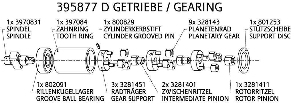
19 5.2. Spare Parts Drawing 19
20 20
21 21
22 22
23 23

24 24

25 25
26 5.3. Spare Parts Drawings for Accessories 26
27 5.4. Installation Tips for Screwdriver Spindle 27
28 6 Maintenance and Upkeep Testing and maintenance can be provided by Operator, disassembly and reassembly of the DEPRAG Screwdriver Spindle should be done by experienced maintenance personnel. Incorrect assembly or disassembly can lead to injury of an operator and damage of the tool. The tool requires little maintenance. If the following service rules are observed, the tool will have a long life expectancy and will remain in a safe condition. Check tool on a regular basis for external damage. Check your maintenance unit on a regular basis, make sure that sufficient oil is in the lubricator (if lubrication is used) and that the adjustment is correct. We recommend for your lubricator DEPRAGOL, part E. After cleaning, the gearing parts have to be greased prior to re-assembly, preferably with Grease, part After assembly fill 2 3 drops of DEPRAGOL into the air inlet nipple. If tool are being used with lubrication, we recommend to have tools tested and cleaned every 12 months (single shift). If tools are being used without lubrication, we recommend to have tools tested and cleaned every 6 months (single shift). Exchange broken or worn plug in tools immediately, for they can cause injury to the Operator. If tool malfunctions, we recommend to send the machine to DEPRAG Wear Parts QUANTITY NAME PART NO. 5 Vane
29 7 Trouble Shooting In the case of a malfunction, check and observe all instructions contained in this technical documentation. If necessary, adjust equipment as needed. Possible faults and their causes are shown below: ERROR REASON SOLUTION Screwdriver does not start Insufficient Power Driver does not shut-off or ratchets No air, Shut-Off valve is closed Valve pin is too short or missing Open Shut-Off valve Test valve pin length according to picture: Actual size of valve Pin and replace valve pin, if necessary Clutch is not engaged Mount clutch correctly - refer to: Range- and exchange of clutch spring Air pressure too low Minimum air pressure should be 90 PSI for maximum performance Restriction in air hose Remove bends or other restrictions Valve Pin too short Hose I.D. is too small Screen Support clogged Vanes are worn Air pressure is too low for required torque value Valve Pin is too long If necessary, please send tool to DEPRAG for service. Check required length of valve pin according to picture: Actual Size of Valve Pin. If needed, exchange valve pin. Use required hose I.D. Clean screen support or exchange with new one Exchange vanes Maintain air pressure of 90 PSI Check length of valve pin, either shorten or replace valve pin (picture: Actual Size of Valve Pin) 29
30 Picture: Actual Size of Valve Pin Attention: When connecting to compressed air supply valve pin may be catapulted out which may cause serious injuries. When verifying the actual size of the valve pin, make sure N O T to hold the screwdriver directed towards yourself or any other person. Verify the actual size only with compressed air connected! 8 Delivery Capacity Please check the delivery capacity in regards to its completeness. QUANTITY NAME PART NO. 1 Operating Instruction Booklet EN 1 Stationary screwdriver spindle A/B/C/D 1 Hand screwdriver set of Clutch spring See chapter: Range and Exchange of Clutch Spring 30
31 9 Accessories - Optional equipment NAME Exhaust connection (in the screwdriver axis) Exhaust connection (right-angled to the screwdriver axis) Spring sleeve cpl. Spring sleeve cpl. (for vacuum suction) PART NO G H A D Operating Screwdriver with a Finder: Installation of the Finder (optional equipment): Remove screw-cap (left-hand thread) from spring sleeve Insert finder and spring into spring sleeve Re-attach screw-cap onto spring sleeve (left-hand thread) Picture: Spring sleeve cpl A with finder and bit Picture: Spring sleeve cpl D with finder and bit 31
32 INFORMATION Finder and bit are not included in the delivery capacity of the spring sleeve. You will find suitable inserting tools in our brochure D 3320 E or on the internet as follows: Screwdriving Technology Selection program: Inserting tools Mount the exhaust connection G (in the screwdriver axis) resp H (right-angled to the screwdriver axis) as follows: 1. Disconnect screwdriver from air supply. 2. Clamp screwdriver spindle always with chucking jaws into a vice, utilizing the flats of the motor housing (otherwise motor- and gearing parts may be damaged). 3. Unscrew the double nipple together with the air connection parts. 4. Take off snap ring (from air connection F) and remove the silencers. 5. Screw off sleeve (AF 19, from air connection F) from valve housing. 6. Mount the sleeve and assemble the o-ring as well as the silencers Install exhaust hose to connection piece as needed and tighten exhaust connection G/H with the circlip Spare Parts Drawing G/H see Spare Parts Drawings for Accessories 10 Storage Unused machines should be stored in a dry, locked area. 32
33 11 Technical Data Manufacturer DEPRAG SCHULZ GMBH u. CO. Address Kurfürstenring Postfach 1352 D Amberg D Amberg Phone 09621/371-0 Fax 09621/ Technical Data: TYPE U 31U 31U 31U Part No A B C D Body Diameter (mm) 22 Drive hex. female (DIN 3126) F6,3 (1/4") Weight (kg/lbs) 0,6 / 1,3 Air pressure (bar/psi) 6,3 / 90 Hose for function control (O.D./I.D.) mm(in.) 4 / 2,5 (.157 / 3 / 32 ) Hose for air supply (O.D./I.D.) mm(in.) 8 / 5,5 (.314 / 7 / 32 ) Torque min. (Nm/in.lbs) 0,3 / 3 0,3 / 3 0,2 / 2 0,2 / 2 Torque max. (Nm/in.lbs) 1,0 / 9 1,4 / 12 2,0 / 18 2,0 / 18 Speed, unloaded (rpm) Noise level (db(a)) 68 Air Consumption (m³/min/cfm) 0,23 / 8 Vibration (m/s²) < 2,5 12 Disposal Unused machines should be stored in a dry, locked area. Disassemble the machine for the required disposal complete. Observe local and environmental regulations for the separation and recycling of materials. Recycle waste oil to avoid environmental contamination! Waste Oil 33
34 13 Declaration of Manufacturer EC-Declaration of Manufacturer in accordance with the CE-Machine-Guideline 98/37/EC, appendix II B DEPRAG SCHULZ GMBH u. CO. Kurfürstenring Postfach 1352 D Amberg D Amberg declares, that the construction of the Stationary Screwdriver Spindle U U U U its design this tool is meant for integration with another machine. Operation of this tool is not permitted unless the complete unit of mounted machines conforms with the national Protection of Labour Regulations, especially in application of the Provision and Use of Work Equipment Regulations Directive. used standards - EN 292 Amberg,
35 14 Service Locations and Authorized Partners ARGENTINA ERIN s.a. Av. Constituyentes 5751 RA-1431 Buenos Aires Tel./Fax: +54 (0) 11 / AUSTRIA Amersin Olschinsky GmbH Kastnerweise 1 A-2441 Mitterndorf a.d. Fischa Tel.: +43 (0)1 / Fax: +43 (0)1 / Internet: information@amersin.at AUSTRALIA De Rossi Industrial Pty. Ltd. Unit 1 2 / 600 Liverpool Road Strathfield South, N.S.W Tel.: +61 (0)2 / Fax: +61 (0)2 / sales@derossi.com.au BELGIUM Aijkens en Zumpolle B.V. Postbus 29 NL-5306 ZG Brakel/Niederlande Tel.: +31 (0)4 18 / Fax: +31 (0)4 18 / Internet: info@zumpolle.net BRAZIL METALFEMA Ltda. Rua Saõ Pedro, 786 Saõ Leopoldo RS BRAZIL ZIP Tel.: +55 (0) 51 / Fax: +55 (0) 51 / Internet: metalfema@metalfema.com.br PR CHINA DEPRAG China DEPRAG Assembly Technologies (Suzhou) Co., Ltd. No. 111, Hong Ye Rd, Blk. 4 Unit D Suzhou , P.R. China Tel.: +86 (0) Fax: +86 (0) Internet: biz@deprag.com.cn d.hua@deprag.com.cn CROATIA SM AUTOMATIKA D.O.O Trg i. Kukuljevica 6 HR Zagreb Tel.: +385(0) Fax: +385(0) Internet: info@sm-automatika.hr CZECHIA/SLOWAKIA DEPRAG CZ a.s. ul. T.G. Masaryka 113 CZ Lázně Bělohrad Tel.: +420 (0) 4 93 / Fax: +420 (0) 4 93 / Internet: info@deprag.cz DENMARK DEPRAG Scandinavia AB Gap Sundins väg 3 SE Eskilstuna Tel.: +45 (0) Fax: +45 (0) Internet: keld.branner@get2net.dk ESTONIA Pneumacon OY Kankurinkatu 4 6 FI Hyvinkää Tel.: +358 (0) 10 / Fax: +358 (0) 10 / Internet: info@pneumacon.fi harri.lindroos@pneumacon.fi Tallinn office: PK 2841, Kose PK EE Tallinn Tel.: +372 (0) Fax: +371 (0) rauno.kolga@pneumacon.fi FINLAND Pneumacon OY Kankurinkatu 4 6 FI Hyvinkää Tel.: +358 (0) 10 / Fax: +358 (0) 10 / Internet: info@pneumacon.fi harri.lindroos@pneumacon.fi FRANCE DEPRAG S.A.R.L. 30 Z.I. du Ried F SCHWEIGHOUSE sur Moder Tel.: / Fax: / depragfrance@evc.net GERMANY Werk Amberg Kurfürstenring 12-18, D Amberg Postfach 1352, D Amberg Tel.: +49 (0) 9621 / Fax: +49 (0) 9621 / Internet: info@deprag.de GREAT BRITAIN DEPRAG Ltd. Unit B4, Pegasus Court Ardglen Industrial Estate Whitchurch Hants RG28 7BP Tel.: +44 (0) Fax: +44 (0) Internet: sales@deprag.co.uk GREECE D. Panayotidis J. Tsatsis s.a. 6 Pireos Street Moschaton Athen Tel.: +30 (0) 1 / Fax: +30 (0) 1 / HUNGARY ADLER 91 Export/Import Kereskedelmi Takarék u. 18/B H-8800 Nagykanizsa Tel./Fax: +36 (0) 93 / adler91adlovits@chello.hu Nóniusz Tool Trading House Ltd. Köbányai út. 47/6 H-1101 Budapest Tel.: +36 (0) 1 / Fax: +36 (0) 1 / Internet: noniusz@noniusz.hu INDIA LEAPTECH Corporation 812 Cosmos, Sector 11 CBD Belapur New Mumbai Tel.: +91 / 22 / /2849 Fax: +91 / 22 / Internet: leaptech@vsnl.net DELHI office: C-332, Sector 10 Noida Tel.: +91 / 120 / Fax: +91 / 120 / BANGALORE office: # 53, Anchor Suddagundapalaya C.V. Raman Nagar Bangalore leaptechbg@vsnl.net IRAN FARA SANAT Co. No. 117, Abzar & Yaragh passage Postcode Tehran Tel.: +98 (0) 21 / / Fax: +98 (0) 21 / NACCARSON AIR TOOLS Co., Ltd. Azadi Ave. No. 625 IR-Tehran Tel.: +98 (0) 21 / Fax: +98 (0) 21 /
36 IRELAND Production Equipment Ltd. Riverside Commercial Estate IRL-Galway Tel.: +353 (0) 91 / Fax: +353 (0) 91 / sales@productionequipment.ie ITALY ATAX S.r.l. Via Carolina Romani, 23 I Bresso/Mi Tel.: / Fax: / info@atax.it Internet: JAPAN NIPPON GESCO Ltd. P.O. Box 255 Kyobashi Tokyo Ginza Matsuyoshi Bldg. 17 8, 7-Chome, Ginza, Chuo-Ku, Tokyo Tel.: +81 (0) 3 / Fax: +81 (0) 3 / mail@gesco.co.jp KOREA (South) Handtools DONG WON POWER-TECH.INC Moonjung-Dong Songpa-Ku Seoul, Korea Tel.: +82 (0) 2 / Fax: +82 (0) 2 / kilpyungdw@dreamwiz.com Screwdriving / Assembly Technology Fatec Co.Ltd. #717 LG Palace B/D Dongkyo-dong Mapo-gu Seoul, Korea Tel.: +82 (0) 2 / Fax: +82 (0) 2 / Internet: fatec@fatec.co.kr LITHUANIA HIDROTEKA P.O. Box 572 LT-3028 KAUNAS Tel.: +370 (0) 37 / Fax: +370 (0) 37 / hidroteka@hidroteka.lt LUXEMBOURG Comptoir Technique et Industriel 321, Route d Arlon L-8011 Strassen Tel.: +352 / Fax: +352 / MALAYSIA FI INNOVATION ENTERPRISE 175, MK D Jalan Bahru Balik Pulau Penang, MALAYSIA Tel. +60/13/ / +60/16/ Fax: +60/4/ farisfi@tm.net.my NETHERLANDS Zumpolle B.V. Postbus 29 NL-5306 ZG Brakel/Niederlande Tel.: +31 (0) 4 18 / Fax: +31 (0) 4 18 / Internet: info@zumpolle.net NORWAY Deprag Scandinavia AB Gap Sundins väg 3 SE Eskilstuna Universal Import Tel.: +47 (0) 2 / Fax: +47 (0) 2 / POLAND INTEGRATOR - RHC ul. Wielki Rów 40 B Torun Tel. +48 / Fax +48 / Internet: leszek.wojtowicz@rhc.com.pl marek.sobocinski@rhc. PORTUGAL Anibal Pires Lda. A.P. 23 E.N. 1 Mourisca do Vouga P-3750 TROFA AGD Tel.: +351 (0) 234 / Fax: +351 (0) 234 / Internet: anibalpires@anibalpires.pt SINGAPORE Testel Systems Pte Ltd 1200 Depot Road # 04-07/09 Singapore Tel.: +65 / Fax: +65 / Internet: sunny@testel.com.sg SLOVENIA MB-NAKLO D.O.O. Toma Zupana 16 SLO-4202 NAKLO Tel.: +386 (0) 4 / Fax: +386 (0) 4 / mb-naklo@siol.net SPAIN ALCOTAN SISTEMAS S.A. p de la Direccion, nmro. 95, local E Madrid Tel.: / Fax: / alcotansis@jazzfree.com BARCELONA office: Passeig de la Mare de Déu del Coll, E Barcelona Tel.: / SWEDEN DEPRAG Scandinavia AB Gap Sundins Väg 3 S Eskilstuna Tel.: +46 (0) Fax: +46 (0) Internet: info@deprag.se SWITZERLAND LIMATEC Automation AG Burgunderstr. 13 CH-4562 Biberist Tel.: +41 (0) 32 / Fax: +41 (0) 32 / Internet: office@limatec.ch TAIWAN I HEN MACHINE Co.Ltd. 6F-9, No. 12, Lane 609, Sec. 5 Chung-Hsin Road, San-Chung City 241 Taipei Hsen Tel.: +886 (0) 2 / Fax: +886 (0) 2 / TURKEY MEKA AUTOMOTIVE ASSEMBLY EQUIPMENTS Dicle Caddesi, Tunca Sokak No : 6 Beysukent - Beytepe - Ankara - TURKEY Tel.: +90 / 312 / Tel.: +90 / 312 / Fax: +90 / 312 / Internet: melih@me-ka.com USA, MEXICO, CANADA DEPRAG INC. 640 Hembry St. / P.O. Box 1554 Lewisville, TX Tel.: +1 / 972 / Fax: +1 / 972 / Toll Free: (800) 4 DEPRAG Internet: deprag@depragusa.com VENEZUELA Suministros Tecnicos SUMTEC C.A. Av. Francisco de Mirando, Centro Plaza Torre C, Piso 16, Officina C16 A-B Urb. Los Palos Grandes Caracas 1060 Tel.: +58 (0) Fax.: +58 (0)
37
38
39
40 DEPRAG SCHULZ GMBH u. CO. Postfach 1352, D Amberg Kurfürstenring 12-18, D Amberg (09621) Fax (09621) Internet: Sep-06 Änderungen vorbehalten / Technical alterations reserved
011652EN. Operating Instruction Booklet. Stationary Screwdriver Spindle MINIMAT-ULTRA
 011652EN Operating Instruction Booklet Stationary Screwdriver Spindle 347-228-31L 347-328-31L 347-528-31L 386370 A 386370 B 386370 C MINIMAT-ULTRA Dear Customer: This tool is the result of more than 75
011731EN. Operating Instruction Booklet. E-Torque Wrench
 011731EN Operating Instruction Booklet E-Torque Wrench MS7DMS MS2DMS 387798 A 387798 B Dear Customer: This tool is the result of more than 75 years of experience in the design and manufacturing of pneumatic
347F A 347F B 347F D 347F C
 011648 EN Operating Instruction Booklet Pneumatic Screwdriver 347F-228 386365 A 347F-328 386365 B 347F-428 386365 D 347F-528 386365 C MINIMAT-F-ULTRA Dear Customer: This tool is the result of more than
Stationary Screwdriver Spindles with Inline Torque Sensor
 Screwdriving technology Automation Air motors Air tools MINIMAT MICROMAT the smallest Piezo-Spindle in the world Stationary Screwdriver Spindles with Inline Torque Sensor Screwdriver Spindles with Function
SENSOMAT. Our pneumatic screwdriver spindles SENSOMAT with mechanical clutch function are particularly suitable for applications
 Screwdriving technology Automation Air motors Air tools Screwdriver Spindles pneumatic SENSOMAT The Control Screwdriver with regulated clutch function Seating torque from 0.3 5 Nm (3 44 in.lbs) n Thread
SENSOMAT. Screwdriver Spindles pneumatic. The Control Screwdriver with regulated clutch function Seating torque from Nm (3 44 in.
 Screwdriving technology Automation Air motors Air tools Screwdriver Spindles pneumatic SENSOMAT The Control Screwdriver with regulated clutch function Seating torque from 0.3 5 Nm (3 44 in.lbs) Thread
ISO Interface. Large capacity. Light weight. Accommodates enclosure IP65. Solenoid Valve (with M Connector) Conforming to ISO
 Conforming to ISO") P-EX01-A Solenoid Valve (with M Connector) Conforming to ISO 1507-1, Large capacity EVS1-01 (Size: 01) EVS1-0 (Size: 0) Light weight Size 01 (-position): 0.6kg Size 0 (-position): 0.18kg Flow rate 1000L/min
P-EX01-A Solenoid Valve (with M Connector) Conforming to ISO 1507-1, Large capacity EVS1-01 (Size: 01) EVS1-0 (Size: 0) Light weight Size 01 (-position): 0.6kg Size 0 (-position): 0.18kg Flow rate 1000L/min
MINIMAT Control Screwdrivers
 Screwdriving technology Automation Air motors Air tools Handheld Screwdriver pneumatic MINIMAT Control Screwdrivers The basic solution for almost all screwdriving tasks angle head design torque from 0.3-65
DOUBLE OCTOMILL TM PRODUCT RANGE
 DOUBLE OCTOMILL TM PRODUCT RANGE Double Octomill insert selection and cutting data recommendations, see page 6. complete insert programme, see page 7. Tool angles: Jo = -11q Jp = - 8q Jf = - 8q Pitch
Inserting Tools for Screwdrivers
 Screwdriving Technology Automation Air Motors Air Tools Inserting Tools for Screwdrivers nbits nsockets nfinders nbit holders With the longest lifetime and highest wear resistance combined with the best
Accessories. Accessories and Fittings for Air Tools & Connecting Air Tools to an Air Distribution Grid
 Screwdriving technology Automation Air motors Air tools Accessories Accessories and Fittings for Air Tools & Connecting Air Tools to an Air Distribution Grid We offer a comprehensive programme of equipment
MINIMAT Screwdrivers. Handheld Screwdriver pneumatic
 Screwdriving Technology Automation Air Motors Air Tools MINIMAT Screwdrivers The basic solution for almost all screwdriving tasks angle head design torque from 0.3-65 Nm / 3 to 575 in.lbs robust highest
Rectangular photoelectric proximity switches
 Rectangular photoelectric proximity switches Features Diffuse sensors with operating distance of 300 mm or 800 mm Through-beam sensors with operating distance of 15 or 50 m Reflex sensors with operating
Type Operating Instructions. Bedienungsanleitung Manuel d utilisation. 2/2-Way Solenoid Valve 2/2-Wege-Magnetventil Électrovanne à 2/2 voies
 Type 5282 2/2-Way Solenoid Valve 2/2-Wege-Magnetventil Électrovanne à 2/2 voies Operating Instructions Bedienungsanleitung Manuel d utilisation 1 OPERATING INSTRUCTIONS The operating instructions contain
Iwaki Electromagnetic Metering Pump EWN-R (Chlorine Dioxide type)
") Iwaki Electromagnetic Metering Pump EWN-R (Chlorine Dioxide type) Instruction manual Thank you for choosing our product. Please read through this instruction manual before use. This manual is intended
Iwaki Electromagnetic Metering Pump EWN-R (Chlorine Dioxide type) Instruction manual Thank you for choosing our product. Please read through this instruction manual before use. This manual is intended
OPERATOR S MANUAL TWIN REGULATOR LUBRO CONTROL UNIT. Part Number Issue 3 Original Instructions (English)
") OPERATOR S MANUAL TWIN REGULATOR LUBRO CONTROL UNIT Part Number 34375 Issue 3 Original Instructions (English) CONTENTS Safety 2 Introduction 3 Parts Included 3 Spare Parts 3 Features and Functions 3 Set
OPERATOR S MANUAL TWIN REGULATOR LUBRO CONTROL UNIT Part Number 34375 Issue 3 Original Instructions (English) CONTENTS Safety 2 Introduction 3 Parts Included 3 Spare Parts 3 Features and Functions 3 Set
Nevro Lead Compatibility
 Nevro Lead Compatibility Directions for Use 91131569-01 REV B CAUTION: Federal law restricts this device to sale, distribution and use by or on the order of a physician. Guarantees Boston Scientific Corporation
Installation instructions
 www.somfy.com Sonesse 0 DCT Installation instructions Ref :505080A Please read installation instructions and programming instructions completely prior to proceeding with installation and programming. Failure
Type Operating Instructions. Bedienungsanleitung Manuel d utilisation. 2/2-Way Solenoid Valve 2/2-Wege-Magnetventil Électrovanne à 2/2 voies
 Type 5282 2/2-Way Solenoid Valve 2/2-Wege-Magnetventil Électrovanne à 2/2 voies Operating Instructions Bedienungsanleitung Manuel d utilisation Contents 1 Operating Instructions... 2 2 Authorized use...
No.1. Side approach mechanism Precise lateral contacting. Catalogue 1.1. Test Probes Test Fixtures
 No.1 in testing solutions in der Prüftechnik Test Probes Test Fixtures Side approach Precise lateral contacting Catalogue 1.1 16 mm, 1 N contact force INGUN for precise lateral contacting -controlled operated
Accessories. Accessories and Fittings for Air Tools & Connecting Air Tools to an Air Distribution Grid
 Screwdriving Technology Automation Air Motors Air Tools Accessories Accessories and Fittings for Air Tools & Connecting Air Tools to an Air Distribution Grid Maintenance Units Oil, Lubrication Grease Balancers
PRODUCT SERVICE MANUAL FOR BK12DHZ PUMPS
 PRODUCT SERVICE MANUAL FOR BK12DHZ PUMPS WARNING This manual, and the GENERAL INSTRUCTION MANUAL SRM00046, should be read thoroughly prior to pump installation, operation or maintenance. Manual No. SRM00095
Made UNDER high pressure
 Made UNDER high pressure Made FOR high pressure THE CONTRINEX HIGH-PRESSURE-RESISTANT INDUCTIVE SENSOR SERIES Contrinex is a leading international high-tech sensor company with headquarters in Switzerland.
Type 6213 EV, 6281 EV
 Type 6213 EV, 6281 EV 2/2-way solenoid valve 2/2-Wege-Magnetventil Électrovanne 2/2 voies Operating Instructions Bedienungsanleitung Manuel d utilisation 1 OPERATING INSTRUCTIONS The operating instructions
ABS Dry Installed Waste Water Pumps Series FR
 A Operating Instruction 3 ABS Dry Installed Waste Water Pumps Series FR Shaft Seal Close-coupled and Bearing Assemblies 3R, 4R, 5R, 5F and 6F! Observe for hazardous liquids that there can be liquid left
Fork through-beam sensors
 Fork throughbeam sensors Features Wide range of sizes: fork widths from 2 to 220 mm Metal housings Integrated evaluation unit Connection by means of S8 connector Degree of protection Adjustable sensitivity
MANUAL. Single charger
 MANUAL Single charger HST-PR-2830 & HST-PR-2830USA for HS-Technik batteries HST-PR-18xx HST-PR-14xx issue date: November 2016 Table of contents Page 1. Basic information...3 1.1. Purpose of this document...3
Air vane motors for special applications
 Screwdriving technology Automation Air motors Air tools Air vane motors for special applications drilling motors 80-600 W milling motor 400 W grinding motors 150-1000 W robust and precise bearing high
KR15. LM Guide Miniature Actuator. KR Series Actuators with Integrated LM Guide and Ball Screw in a Compact Stainless Steel Body. CATALOG No.
 LM Guide Miniature Actuator KR1 KR Series Actuators with Integrated LM Guide and Ball Screw in a Compact Stainless Steel Body US, EPC Patent pending CATALOG No.76E LM Guide Actuator KR1 Miniature LM Guide
Wear Resistant Tubing
 Wear Resistant Tubing New RoHS 1/ Abrasion: Approx. (Compared with SMC polyurethane tubing TU series) 3 Description Wear resistant tubing TUZ series Polyurethane tubing TU series Maximum abrasion (mm)
FLENDER ZAPEX couplings. Type ZWT. Operating instructions BA 3505 EN 10/2011. FLENDER couplings
 FLENDER ZAPEX couplings Type ZWT Operating instructions FLENDER couplings FLENDER ZAPEX couplings Type ZWT Operating instructions Translation of the original operating instructions Technical data Notes
NANOMAT Control Screwdrivers
 Screwdriving technology Automation Air motors Air tools Screwdriver Spindles pneumatic NANOMAT Control Screwdrivers The Screwdriver for your micro assemblies straight design - torque from 8 Nmm - 300 Nmm
Compressed Air Conditioning. accessories. One Stop Shop process reliable efficient economical high degree of reusability
 Screwdriving technology Automation Air motors Air tools Compressed Air Conditioning and Accessories One Stop Shop process reliable efficient economical high degree of reusability DEPRAG offers a comprehensive
The new STx chain hoist NEW. Sophisticated technology prepared for the future
 The new STx chain hoist 03.2018 NEW Sophisticated technology prepared for the future The new STx chain hoist Sophisticated technology prepared for the future Our experts have undertaken to keep reviewing
BOLL Automatic Filter TYPE The Compact Design Two-Chamber Filter. BOLL & KIRCH Filterbau GmbH
 BOLL Automatic Filter TYPE 6.72 The Compact Design Two-Chamber Filter BOLL & KIRCH Filterbau GmbH THE TASK Perfect pre-treatment In order to ensure that large combustion engines or mechanical processing
UView Mini Transilluminator
 UView Mini Transilluminator Instruction Manual Catalog #166-0531 Hardware Instruction Manual The UView mini transilluminator is suitable for research use only. It must be used by specialized personnel
Ceram 4-way Pneumatic Directional Control Valve Tough enough to survive, no matter where in the world you send it.
 2 Features Valve options Accessories Ceram 4-way Pneumatic Directional Control Valve Tough enough to survive, no matter where in the world you send it. The secret s a ceramic seal. Inside the valve a pair
Infographics on Electromobility (January 2019)
") Infographics on Electromobility (January 2019) Publisher: BMW Group Corporate Communications Electromobility Last Update: 04.01.2019 Contact: presse@bmw.de ELECTROMOBILITY IN GERMANY. SHARE IN NEW REGISTRATIONS
Infographics on Electromobility (January 2019) Publisher: BMW Group Corporate Communications Electromobility Last Update: 04.01.2019 Contact: presse@bmw.de ELECTROMOBILITY IN GERMANY. SHARE IN NEW REGISTRATIONS
PREVIEW. Fieldbus System for Distributed I/O NEW PRODUCTS
 NEW PRODUCTS PREVIEW Fieldbus System for Distributed I/O! Dual Port EtherNet/IP TM Gateway controls up to 8 Valve Manifolds and 8 Input blocks Controls up to 128 Inputs and 128 Outputs Supports QuickConnect
PRODUCT SERVICE MANUAL. BK6DHZ(C)-250, 275, 312 and 400 PUMPS
-250, 275, 312 and 400 PUMPS") PRODUCT SERVICE MANUAL BK6DHZ(C)-250, 275, 312 and 400 PUMPS WARNING This manual, and the GENERAL INSTRUCTION MANUAL, SRM00046, should be read thoroughly prior to pump installation, operation or maintenance.
PRODUCT SERVICE MANUAL BK6DHZ(C)-250, 275, 312 and 400 PUMPS WARNING This manual, and the GENERAL INSTRUCTION MANUAL, SRM00046, should be read thoroughly prior to pump installation, operation or maintenance.
Exchange of rollers from the XTS-Mover
 Service documentation for AT901-0050-0550 and AT9011-00x0-0550 Version: Date: 1.0 0.10.017 Table of contents Table of contents 1 Foreword... 5 1.1 Notes on the documentation... 5 1. Documentation issue
Type Operating Instructions. Bedienungsanleitung Manuel d utilisation. 2/2-way solenoid valve 2/2-Wege-Magnetventil Électrovanne 2/2 voies
 Type 5404 2/2-way solenoid valve 2/2-Wege-Magnetventil Électrovanne 2/2 voies Operating Instructions Bedienungsanleitung Manuel d utilisation Contents 1 Operating instructions...2 2 Intended use...3 3
Parts Manual. cascade
 c Parts Manual Model Serial Number 65F Sideshifter 65F-SSS-B796 R1 corporation OR Write: Cascade Corporation, P.O. Box 20187, Portland, OR 97220 Internet: www.cascorp.com I NSPECTION & MAINTENANCE WARNING:
Single-acting pneumatic cylinder type ECS
 Single-acting pneumatic cylinder type ECS Information is only for informational purpose. All specifications are subject to change without notice. 1 2015-06-18 issue: 2 Single-acting pneumatic cylinder
Assembly and Maintenance Manual Type AS
 Assembly and Maintenance Manual Type AS Hatschekstr.36 69126 Heidelberg Germany Tel +49(0)6221 30470 Fax +49(0)6221 304731 info@stieber.de www.stieber.de Date of issue: 30.05.2018 GB Revision: 0 U:\EngUsers\!ProduktDoku\1AAA_Einbauerklaerung_Wartungsanleitung_Konformitaetserklaerung\1AAA_Wartungsanleitungen\Orginal_Worddatei\_AS.docx
SERIES G3DB/AG3DB ELEVATOR
 TM INSTRUCTIONS AND PARTS LIST SERIES G3DB/AG3DB ELEVATOR WARNING This manual, and GENERAL INSTRUCTIONS MANUAL, CA-1, should be read thoroughly prior to pump installation, operation or maintenance. SRM00059
Universal Charging and Testing Unit FPU-1 for Bladder, Piston and Diaphragm Accumulators
 Universal Charging and Testing Unit FPU-1 for Bladder, Piston and Diaphragm Accumulators 1. Description 1.1. Function The HYDAC charging and testing unit FPU-1 is used to charge accumulators with nitrogen
OPERATING AND MAINTENANCE INSTRUCTIONS HYDRAULIC ELECTRICAL PUMPS HAM (Manual control) HAE (Electrical control)
 HAE (Electrical control)") OPERATING AND MAINTENANCE INSTRUCTIONS HYDRAULIC ELECTRICAL PUMPS HAM (Manual control) HAE (Electrical control) Part Nr : HA M 4 6 2 1 B C 1. Essential safety requirements. 2. Technical Characteristics.
OPERATING AND MAINTENANCE INSTRUCTIONS HYDRAULIC ELECTRICAL PUMPS HAM (Manual control) HAE (Electrical control) Part Nr : HA M 4 6 2 1 B C 1. Essential safety requirements. 2. Technical Characteristics.
Guide Ball Bushing NEW
 NEW Guide Ball Bushing Contributes to compact the system Achieves load rating more than twice the Linear Bushing with the same dimensions (model LG-S) Various combinations of nut and shaft are available
Pneumatic Corner Drill
 Maschinenfabrik GmbH Pneumatic Corner Drill Type 2 1602 0030 Illustration can differ from the original Operation and Maintenance Manual Compiled: 31.07.08 216020030_en.doc Page 1 of 12 TECHNICAL SPECIFICATION
SBS-Control. Table of contents. Operating Instructions BKS24-9A. Operating Instructions
 Operating Instructions BKS24-9A Operating Instructions BKS24-9A Table of contents Operating Instructions 1 Operating controls and indicators 2 2 Preparations for faultless commissioning and operating 3
Roll Up WireFree IR. Installation instructions
 www.somfy.com TM Roll Up WireFree IR Installation instructions Ref :5059844 Safety This Somfy product must be installed by a professional motorization and home automation installer, for whom these instructions
Total credit to the non-financial sector (core debt), % of GDP Table F1.1
, % of GDP Table F1.1") Total credit to the non-financial sector (core debt), % of GDP Table F1.1 2012 2013 2014 2015 2016 Q2 16 Q3 16 Q4 16 Q1 17 Q2 17 Argentina 62.6 66.4 64.6 75.5 75.3 81.7 80.1 75.3 71.6 72.7 Australia 208.0
Total credit to the non-financial sector (core debt), % of GDP Table F1.1 2012 2013 2014 2015 2016 Q2 16 Q3 16 Q4 16 Q1 17 Q2 17 Argentina 62.6 66.4 64.6 75.5 75.3 81.7 80.1 75.3 71.6 72.7 Australia 208.0
Precision Ball Screw/Spline. Rotary-Nut Series Linear Motion + Rotary Motion BNS/NS. CATALOG No.327-1E
 Precision Ball Screw/Spline Rotary-Nut Series Linear Motion + Rotary Motion BNS/NS CATALOG No.7-1E Contents Rotary-Nut Series Precision Ball Screw/Spline BNS/NS Japanese patent No. 7 (model NS), 77 (model
Hand pump PUMP1000-4L-CONTROL. User manual
 Hand pump PUMP1000-4L-CONTROL User manual Safety guidelines and symbols High product safety Follow instructions Definition of guidelines and symbols Warning Caution Our products correspond to the current
Fork through-beam sensors
 Fork throughbeam sensors Features Wide range of sizes: fork widths from 2 to 220 mm Metal housings Integrated evaluation unit Connection by means of S8 connector Degree of protection Adjustable sensitivity
Instruction Sheet. Modular Air Pumps IMPORTANT RECEIVING INSTRUCTIONS DESCRIPTION
 Instruction Sheet Modular Air Pumps L2202 Rev. O 06/97 IMPORTANT RECEIVING INSTRUCTIONS Visually inspect all components for shipping damage. If any shipping damage is found, notify carrier at once. Shipping
Pneumatic Torque Motors
 Pneumatic Torque Motors Contents and Torque Motor Selection Contents Torque Motor Selection... page 2 Torque Controlled Shut Off... page 4 SC Series... page 4 SD Series... page 6 F Series... page 8 Accessories...
3M Overhaul Service Kit
 SERVICE INSTRUCTIONS FOR 3M 12,000 RPM 5 in. (127 mm) and 6 in. (150 mm) RANDOM ORBITAL SANDERS 3M Overhaul Service Kit The part number 20347, 3M Overhaul Service Kit, contains all the replacement parts
Assembly and Maintenance Manual Type ASNU
 Assembly and Maintenance Manual Type ASNU Hatschekstr.36 69126 Heidelberg Germany Tel +49(0)6221 30470 Fax +49(0)6221 304731 info@stieber.de www.stieber.de Date of issue: 30.05.2018 GB Revision: 0 U:\EngUsers\!ProduktDoku\1AAA_Einbauerklaerung_Wartungsanleitung_Konformitaetserklaerung\1AAA_Wartungsanleitungen\Orginal_Worddatei\_ASNU.docx
INSTALLATION GUIDE NI 9921/9922 Outdoor IP Enclosure For NI WLS-9000 Series Devices
 INSTALLATION GUIDE NI 99/99 Outdoor IP Enclosure For NI WLS-9000 Series Devices This guide describes how to install and use the National Instruments 99 and National Instruments 99 outdoor IP enclosures.
Type Operating Instructions. Bedienungsanleitung Manuel d utilisation. 2/2-way solenoid valve 2/2-Wege-Magnetventil Électrovanne 2/2 voies
 Type 6027 2/2-way solenoid valve 2/2-Wege-Magnetventil Électrovanne 2/2 voies Operating Instructions Bedienungsanleitung Manuel d utilisation 1 OPERATING INSTRUCTIONS The operating instructions contain
Type 3320, Service Manual. Serviceanleitung Service Manuel
 Electromotive 2/2-way valve Elektromotorisches 2/2-Wege-Ventil Vanne électromotorisée à 2/2 voies Service Manual Serviceanleitung Service Manuel We reserve the right to make technical changes without notice.
HST-BL-2830MS & HST-BL-2830MS-USA
 HST-BL-2830MS & HST-BL-2830MS-USA Release date: 02/2017 High - System - Technik Im Martelacker 12 D-79588 Efringen-Kirchen Phone 0 76 28-91 11-0 Fax 0 76 28-91 11-90 E-Mail: info@hs-technik.com Web: www.hs-technik.com
Drive systems & electrical energy production for construction, local government structures, large infrastructure and industrial projects
 09.2007 / a 4183 en - 03.2008 / b Drive systems & electrical energy production for construction, local government structures, large infrastructure and industrial projects www.leroy-somer.com Drive systems
INSTALLATION GUIDE NI WSN-3291 Outdoor IP Enclosure For NI WSN-32xx Series Devices
 INSTALLATION GUIDE NI WSN-3291 Outdoor IP Enclosure For NI WSN-32xx Series Devices This installation guide describes how to install and use the National Instruments WSN-3291 outdoor IP enclosure. The NI
Type Operating Instructions. Bedienungsanleitung Manuel d utilisation
 2/2-way angle seat control valve 2/2-Wege-Schrägsitzregelventil Vanne de réglage à siège incliné 2/2 voies Operating Instructions Bedienungsanleitung Manuel d utilisation We reserve the right to make technical
Options for the Ball Screw QZ Lubricator Wiper Ring W
 Options for the Ball Screw Lubricator Wiper Ring W CATALOG No.322-1E OPTIONS For Ball Screws, dust-prevention and lubrication accessories are available. You can make a selection according to the application
Assembly Instructions
 Rev.. Assembly Instructions - Hand Spray Valve SMS-6 Page of 20 Assembly Instructions Hand Spray Valve SMS-6 Article Number: S6- NOTE Please read the Assembly Instructions carefully before first using
Lifting Instructions for 1336 PLUS and FORCE D Frame Drives
 Installation Instructions Lifting Instructions for 1336 PLUS and FORCE D Frame Drives This publication will guide you through the steps needed to properly lift and mount the following drives: 1336 PLUS
Pressure relief valve
 Pressure relief valve Operating manual Series DHV 712 Version BA-2015.10.20 EN Print-No. 300 510 TR MA DE Rev001 ASV Stübbe GmbH & Co. KG Hollwieser Straße 5 32602 Vlotho Germany Phone: +49 (0) 5733-799-0
Type 0283, Operating Instructions. Bedienungsanleitung Manuel d utilisation. 2/2-way solenoid valve 2/2-Wege-Magnetventil Électrovanne 2/2 voies
 Type 0283, 0293 2/2-way solenoid valve 2/2-Wege-Magnetventil Électrovanne 2/2 voies Operating Instructions Bedienungsanleitung Manuel d utilisation Contents 1 The operating instructions...2 2 Intended
Parts Manual. cascade
 c Parts Manual Model F-Series Sideshifter Serial Number -SSS-A156R0 cascade corporation For Technical Assistance call: 800-227-2233, Fax: 888-329-8207 To Order Parts call: 888-227-2233, Fax: 888-329-0234
Working Instructions Translation
 WIDOS Einsteinstr. 5 Phone +49 (0) 71 52 99 39-0 W. Dommer Söhne GmbH D-71254 Ditzingen-Heimerdingen Fax +49 (0) 71 52 99 39-40 Website: www.widos.de Email: info@widos.de Working Instructions Translation
Knife gate valve JTV. Data is only for informational purpose. All specifications are subject to change without notice issue 11
 Knife gate valve JTV Data is only for informational purpose. All specifications are subject to change without notice. 1 2015-05-21 issue 11 Knife gate valve JTV Stafsjö s knife gate valve JTV is reliable
SERIES OPERATION AND MAINTENANCE MANUAL
 SERIES OPERATION AND MAINTENANCE MANUAL This manual CONTAINS IMPORTANT WARNINGS, S and OTHER INSTRUCTIONS. Read and understand the instruction manual Carefully, before use and retain it for reference.
Tension Meter. Edition FT 03.E. FT Series. Instruction Manual. Valid as of: Please keep the manual for future reference!
 Tension Meter FT Series S C H M I D T c o n t r o l i n s t r u m e n t s Edition FT 03.E Model FT Instruction Manual Valid as of: 01.09.2011 Please keep the manual for future reference! Contents 1 Warranty
Max. flow capacity of 5,000 L/min and max. discharge head of 98m. The world s largest class fluoroplastic magnetic drive pump.
 MDW series Magnetic drive pumps Max. flow capacity of 5,000 L/min and max. discharge head of 98m. The world s largest class fluoroplastic magnetic drive pump. The MDW series are the largest class fluoroplastic
OPERATING INSTRUCTIONS. HTL-DSX Dedicated Square Drive Wrench
 OPERATING INSTRUCTIONS HTL-DSX Dedicated Square Drive Wrench CONTENTS Contents 2 Safety 2-3 Warranty 3 Connecting the tool 3-4 Setting the torque 4-5 Operating the wrench 5-6 Maintenance 6 Troubleshooting
High torque stainless steel motors ADVANCED LINE. Stainless Steel Air Motors from 20 W / 0.03 Hp up to 1.2 kw / 1.6 Hp
 Screwdriving technology Automation Air motors Air tools ADVANCED LINE Stainless Steel Air s from 20 W / 0.03 Hp up to 1.2 kw / 1.6 Hp NEW MOTOR RANGE High torque motors made from stainless steel: Our ADVANCED
THE WITTUR ANSWER TO THE MACHINE ROOMLESS MARKET REQUIREMENTS. MRL W Line. EMOTION IN MOTION
 THE WITTUR ANSWER TO THE MACHINE ROOMLESS MARKET REQUIREMENTS EMOTION IN MOTION ADVANCED FEATURES THE WITTUR ANSWER TO THE CURRENT MRL MARKET REQUIREMENTS The, Wittur s new generation of machine roomless
Stainless Steel Air-Vane Motors
 Screwdriving technology Automation Air motors Air tools Stainless Steel Air-Vane Motors up to 1.2 kw / 1.6 Hp corrosion free oilfree sealed The DEPRAG line of air motors merges an attractive cost to power
Quick-Disconnect Coupling one-hand operation Push Pull ND 5, connecting thread G 1/4,max. operating pressure 500 bar
 Issue 12-2013 Quick-Disconnect Coupling one-hand operation Push Pull ND 5, connecting thread G 1/4,max. operating pressure 500 bar Figure 1: Coupling complete Figure 4: Coded coupling, complete Table of
Original Operating Manual
 matev GmbH Nürnberger Str. 50 90579 Langenzenn T +49 (0) 9101 9087-0 F +49 (0) 9101 9087-20 info@matev.eu www.matev.eu Original Operating Manual Snow blade SRM-FB 120 CD Angle adjustment mechanical Version
RO Automatic trailer coupling. Repair instructions. 5KPVM02000 Towing Hitch Automatic Rockinger RO244A
 utomatic trailer coupling Repair instructions 5KPVM02000 Towing Hitch utomatic Rockinger RO244 5KPVM02010 Towing Hitch utomatic Rockinger foot operated RO244L Contents 1 General Validity and application
One machine multiple applications.
 One machine multiple applications. image 1 image 2 image 3 image 4 Manufacturing of engineering plastics. Processing of PVC. Manufacturing of TPE. Manufacturing of master batches. Coperion worldwide. >
Type 3360, Service Manual. Serviceanleitung Service Manuel
 Electromotive control valve Elektromotorisches Regelventil Vanne de régulation électromotorisée Service Manual Serviceanleitung Service Manuel We reserve the right to make technical changes without notice.
Type Operating Instructions. Bedienungsanleitung Manuel d utilisation
 Type 0131 2/2- or 3/2-way solenoid valve 2/2- oder 3/2-Wege-Magnetventil Électrovanne 2/2 ou 3/2 voies Operating Instructions Bedienungsanleitung Manuel d utilisation 1 OPERATING INSTRUCTIONS The operating
PLASTIC WELDING. New! TRIAC AT. Intelligent and robust.
 PLASTIC WELDING TRIAC AT New! Intelligent and robust. Hot air tool TRIAC AT The new TRIAC AT is an intelligent yet robust hot air tool for welding and shrinking plastic. It is designed for the needs of
Schedule of Accreditation issued by United Kingdom Accreditation Service 2 Pine Trees, Chertsey Lane, Staines-upon-Thames, TW18 3HR, UK
 2 Pine Trees, Chertsey Lane, Staines-upon-Thames, TW18 3HR, UK Accredited to ISO/IEC 17021-1:2015 to provide environmental 4th Floor Vivo Building 30 Stamford Street SE1 9LQ United Kingdom Contact: Mr
3M Overhaul Service Kit
 SERVICE INSTRUCTIONS FOR 3M 12,000 RPM 3 in. (77 mm) RANDOM ORBITAL SANDERS 3M Overhaul Service Kit The part number 20346, 3M Overhaul Service Kit, contains all the replacement parts that naturally wear
D E. PARTS LIST Fx25-2 HYDRAULIC BREAKER APPLICABLE SERIAL NUMBER 6001 AND UP
 902306-D101020-1E PARTS LIST Fx25-2 HYDRAULIC BREAKER APPLICABLE SERIAL NUMBER 6001 AND UP SUPPLY PERIOD OF SPARE PARTS Thank you for purchasing a Furukawa Rock Drill product. Please note that the supply
Universal Charging and Testing Unit FPU-1 for Bladder, Piston and Diaphragm Accumulators
 Universal Charging and Testing Unit FPU-1 for Bladder, Piston and Diaphragm Accumulators 1. DESCRIPTION 1.1. FUNCTION The HYDAC charging and testing unit FPU-1 is used to charge accumulators with nitrogen
Parts Manual. cascade
 c Parts Manual Model Serial Number F-Series Sideshifter -SSS-A147R0 cascade corporation For Technical Assistance call: 800-227-2233, Fax: 888-329-8207 To Order Parts call: 888-227-2233, Fax: 888-329-0234
OPERATION AND MAINTENANCE MANUAL
 WREN IBT SERIES HYDRAULIC TORQUE WRENCHES IBT SQUARE DRIVE SERIES OPERATION AND MAINTENANCE MANUAL FOR WREN Products: POINT 75, 1IBT, 3IBT, 5IBT, 8IBT, 10IBT, 20IBT, 25IBT, 35IBT, 50IBT SQUARE DRIVE HYDRAULIC
ULT Series Repair Manual
 ULT Series Repair Manual PO Box 16460, Portland, OR 97292-0460 503-254-6600 Fax 503-255-2615 Contents Page Number 1. Recommended Tools 2 2. Special Repair Fixtures 3-5 3. Disassembly and Reassembly of
VACUUM CONVEYOR SYSTEM
 ISO 9001 CERTIFIED 0575 Ⅱ 1Dc 90 C / Ⅱ 2 GD c 100 C VACUUM CONVEYOR SYSTEM Why!! We are VMECA Vacuum conveyor system? Minimal Maintenance Low Noise Level Automatic Filter Cleaning System Simple to Installation
Type 8635 Remote-Positioner. Zusatzanleitung. English Deutsch Français
 Type 8635 Remote-Positioner Installation on process valves with internal air flow (series 2103, 2300, 2301) Anbau an Prozessventile mit interner Luftführung (Reihe 2103, 2300, 2301) Intégration sur des
Centering Unit. Alignment and positioning of transferred workpieces. MACM Series. Table. Max. allowable load weight: 2205 lbs (1000 kg) (MACM10)
 (MACM10)") Centering Unit Alignment and positioning of transferred workpieces Contributes to space saving on conveyor lines Heavy workpieces can now be aligned and positioned with small cylinders, resulting in compact
Centering Unit Alignment and positioning of transferred workpieces Contributes to space saving on conveyor lines Heavy workpieces can now be aligned and positioned with small cylinders, resulting in compact
Diaphragm Valve Type 14 Pneumatic Model Type AV
 ASAHI AV Valves Serial No. H A015 E 1 Diaphragm Valve Type 14 Pneumatic Model Type AV User s Manual (1) General operating instructions Contents (2) General instructions for transportation, unpacking and