437/737 BENCH SCALE. INSTALLATION and MAINTENANCE MANUAL
|
|
|
- Louise Goodman
- 5 years ago
- Views:
Transcription

1 437/737 BENCH SCALE INSTALLATION and MAINTENANCE MANUAL Emery Winslow Scale Company 73 Cogwheel Lane Seymour, CT Rev Nov 2005
2 Table of Contents SECTION 1 INTRODUCTION TO COMPONENTS 3 Description Functional Overview Weighing System Components SECTION 2 SYSTEM INSTALLATION 6 Installation Requirements Scale Installation Transducer Enclosure Installation Tubing Installation Tube Fitting Nut Installation SECTION 3 PURGING THE SYSTEM 10 Transducer Components Fill the Filling Tool Connect the Tubing Lines Purge the Tubing and Load Cells Gauge the Load Cells Instrumentation Hookup SECTION 4 PERIODIC INSPECTION 16 SECTION 5 SPARE PARTS 17 SECTION 6 TROUBLESHOOTING 18 General Troubleshooting Service Information SECTION 7 EVALUATION and REPAIR PROCEDURES 20 Transducer Strain Gauge Evaluation- Model 175 Transducer Strain Gauge Replacement- Model 175 Diaphragm Replacement 2
3 SECTION 1 - COMPONENT INTRODUCTION Description Emery Winslow weigh scales are designed for durability and long life. They use several high precision Hydrostatic Load Cells and a Hytronic Totalizer to measure the weight on the scale. Functional Overview 1) The mass to be weighed is placed on the scale. 2) The Hydrostatic Load Cell is compressed under the load and outputs a pressure signal. 3) The pressure signal is transmitted, via capillary tubing, to a Hytronic Transducer. 4) The Transducer outputs an electrical millivolt signal to the instrumentation. 5) The electrical signal is directly proportional to the weight of the mass. 3
4 Weighing System Components 1. Weighsquare: The weighsquare typically consists of a removable cover, one (1) hydrostatic load cell, and assembly consisting of a top frame, two (2) torque arms and a base frame. 2. Hydrostatic Load Cell: The Model 102 Hydrostatic Load Cell consists of a head assembly, a base assembly and a diaphragm. The load cell works on the formulapressure (PSI) = load (lb) area (sq in) The area of the cell is constant, therefore, the pressure output is proportional to the load. The vertical motion of the load cell is less than from no load to full load conditions. Load Cell Gauging: The load cell must be filled with a precise amount of cell fluid to function as designed. To determine if the cell is filled with the recommended amount of fluid, a procedure called "Gauging" is used. The process of "Gauging a load cell" is similar to gaping a spark plug. A go/no-go gauge, such as a feeler gauge, is used to precisely determine the distance between 2 points in the load cell body. Cell Fluid: The typical cell fluid used in the scale is Emery Winslow BL-15. This inert blue fluid is supplied with each system as part of the accessory package. DO NOT use automotive engine oil or hydraulic brake fluid. Filling Tool: A filling tool is used to fill the system with cell fluid. 3. Tubing: The 1/8" OD tube transmits the Hydrostatic pressure signal from the load cell to the Hytronic Totalizer. The tubing is thick wall capillary tubing. Stainless steel tubing is recommended for corrosive or food process environments and is supplied standard on weighsquare systems. 4. Fittings: The tubing is connected with compression fittings. The fitting consists of a body, two ferrules (front and back) and a nut. 4


5 5. Hytronic Transducer: In single load cell systems, the load cell output pressure is transmitted to the transducer. A transducer in the unit produces an electronic signal that is proportional to the input pressure from the load cell. 6. Fill Valve: In weighsquare systems without a transducer, a fill valve is supplied. The fill valve is used to purge the tubing and load cell. 7. Digital Indicator: Most strain gauge digital indicators can interface with the Emery Winslow Hytronic Transducer. For details about the system's indicator, see the digital indicator manual. 5
6 SECTION 2 - SYSTEM INSTALLATION When installing an Emery Winslow weighsquare, reference the Installation Drawings in conjunction with this manual. If you have questions, or need further assistance, please contact the Emery Winslow Service Department. We will provide assistance to ensure the installation will result in a properly functioning weigh system. Installation Requirements Base must be installed on a rigid, flat surface. Each corner of the scale must have rigid support for accurate weighments. The scale can be installed in a sloped, non-leveled position. Scale Installation Place the scale on the floor or bench in the proper location. Ensure that the base makes contact with the floor/bench at the 4 corners. If any corner is not rigid, use shims or adjust the leveling feet (if supplied) to obtain the necessary support. The base can be anchored to hold it securely in place. Use the mounting holes as a template to install the anchors. If leveling feet are supplied, remove the feet and use these holes as anchoring holes. Install the anchor bolts per the manufacturer's instruction. Remove the cover and set the rotational stops to a gap of 0.06" (4 places). For factory purged and calibrated systems - Remove the shipping stop from the load cell and check the load cell gauging. Purge and fill the load cell if the gauging is out of range (see Section 3). Verify the calibration of the scale. If the calibration is within the accuracy band, the scale is ready for use. If the transducer enclosure is not factory installed on a pedestal, the following applies. 6
7 Transducer Enclosure Installation The standard transducer enclosure supplied is a Nema 4x FRP (fiberglass reinforced plastic) enclosure. Other materials such as painted carbon steel or stainless steel are available. Besides housing the transducer, this enclosure also serves as the field interface box for the signal cables. A terminal strip is provides for that purpose. If the transducer enclosure is not factory installed on a pedestal, it will need to be field mounted. standard transducer enclosure When laying out the installation, the transducer enclosure should be installed as close to the load cells as possible. On a standard system, 25' of tubing per load cell is included. Note: The totalizer should not be mounted more than 4 feet above the scale. 7
8 Tubing Installation Install the Tubing Runs - When laying out and installing the tubing, be guided by the following notes and tubing diagram. Important Notes: A) Tubing must be protected from damage and should be run through minimum 1" diameter conduit. (Minimum 1.5 diameter for stainless tubing.) B) Conduit sweep(s) should have minimum 6" radius. When using stainless steel tubing, do not utilize more than (3) three 90º sweeps in the conduit run. C) Tubing runs should be as short as possible. D) When planning tubing runs, avoid steam lines and other sources of heat or cold which cause large temperature changes from ambient. E) In each tubing run, leave a few extra feet of tubing in the run. Coil this extra tubing and place it in a safe, accessable location. This extra tubing will facilitate making a new connection at the load cell or totalizer in the future. F) When cutting the tubing, use a good quality pipe cutter to produce a clean and burr free end for the Nut and Ferrules to slide over. Do not use any type of pincher cutter to cut the tubing. After cutting the tubing, inspect the cut end for any burrs. Use a fine, hard file to remove the burr from the edge of the tubing. Check the tubing bore to make sure it has not been pinched closed during the cut. G) A brass fitting must never be used with stainless steel tubing. Brass is not strong enough to make a leak-proof connection. Tube Fitting Installation Each load cell has two fittings. They are interchangeable in their function. One connects to the tubing and the other is used to purge the cell of air during start up and maintenance. Connect the tube to the fitting that provides the most protection for the tubing. The other fitting then becomes the purge fitting. When installing the fitting nut on the tubing, please see the installation instruction on drawing A-34055, shown on the next page. IMPORTANT Install the tubing through the totalizer enclosure's bulkhead connector before installing the fitting nut on the end of the tubing. If the nut and ferrules do not slide over the tubing, use a fine hard file to remove the burr from the edge of the tubing. 8
9 To continue the installation process, go to Section 3. 9

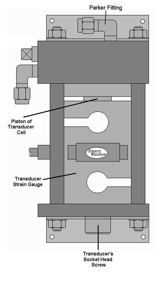
10 SECTION 3 - PURGING AND FILLING THE SYSTEM Transducer Components The Transducer Manifold directs the cell fluid from the load cell to the transducer cell. The Parker Fitting is used to add or remove cell fluid from the individual load cell circuits. The Filling Tool is attached to the Parker Fitting to fill the system. The Valve opens or closes the load cell / transducer cell circuit to the Parker Fitting. Refer to the schematic diagram below. The valve wrench is used to open and close the valve. 10
11 Fill the Filling Tool Pull out the T-handled follower rod. When it is fully extended pull the rod sideways to latch the groove of the rod into the key hole slot of the cap. Remove the head from the filling tool. Fill the filling tool with Cell Fluid to within one inch of the top. Reassemble the filling tool. Screw the head on tight. Release the follower rod. Holding the head up, open the Purge Fitting slightly to let the air escape. Keep it open until oil flows out. While holding the head end up, pump the handle several times to clear the pump and the connecting tube of air. The Filling Tool is now purged and ready. During use check for free travel of the follower rod frequently by pulling the rod outward. If the follower rod has one inch or less of free travel fill the Filling Tool again. An empty Filling Tool will fill the system with air and cause weighing errors. 11
12 Connect the Tubing Lines Install the tubing from the load cell to the transducer, through the enclosure's bulkhead connector. Do not connect the tube to the load cell yet. Before attaching the fitting nut to the tube, please review the installation of the Double Ferrule Tube Fitting. Connect the tube from the load cell to the tube fitting on the Transducer Manifold. Purge Air From The Tubing and Load Cell Attach the Filling Tool to the Parker Fitting. Remove the cap from the Parker Fitting on the Transducer Manifold. Screw on the Filling Tool Hose by using the swivel nut on the hose. Place the cap to the side. After filling the system this cap must be replaced. Perform the purging steps below for the tubing line and load cell. Use the Valve Wrench to open the Valve and pump fluid through the tubing until the flow is free of air. Catch the purged cell fluid in the original container. To purge the load cell, connect the tubing to the Tube Fitting of the load cell. Then remove the cap from the Purge Fitting of the cell and attach the short length of Purge Line. Place the other end in the cell fluid container. 12
13 Pump the fluid through the Manifold, connecting tubing, and the load cell until the air bubbles stop coming out of the open end of the purge line. Remove the purge line and replace it with the fitting cap. Tighten the cap while fluid is seeping out of the connection. Note: The captured cell fluid can be reused if it is not contaminated. If the captured cell fluid is contaminated with dirt or other fluids, dispose of in accordance with applicable regulations. 13
14 Gauge the Load Cell- 102 To fill each load cell, open the valve and pump additional fluid into the system circuit until the recommended feeler gauge reading is reached. As you pump fluid into the cell the gauging gap will increase on the load cell. After the cell is gauged to the recommended gauging, close the valve. If the cell is accidentally overfilled you can remove fluid by slightly loosening the purge fitting cap. This will let the cell fluid leak out slowly. The load cell must be filled with the fluid to the recommended gauging. Consult the installation drawing supplied with your system. Typical load cell gauging is listed in the chart below: Model Number Capacity Part Number Gauging M1 1,500 lb B /8" +1/32" M1 2,500 lb B /8" +1/32" M1 3,500 lb B /8" +1/32" M2 5,000 lb B /16" +1/32" M2 10,000 lb B /16" +1/32" Record the final gauge reading for each load cell in the system. Remove the Filling Tool and replace the cap on the parker fitting. Note: Remove any excess fluid from the fittings on the totalizer manifold and load cell. This will allow prompt detection of leaks should they occur. 14
15 Instrumentation Hookup The electrical output of the weigh system is a millivolt level signal. Typically, a terminal strip is located in the totalizer enclosure to allow wiring the weigh system to a digital indicator or process control instrumentation. The color code for the totalizer transducer cable is: 4 wire transducer Red + excitation Black - excitation Not wired + sense Not wired - sense Green + signal White - signal Reference the indicator or process instrumentation manual to determine the proper load cell cable hookup. A typical wiring diagram for a digital indicator is shown below. Note: If Emery Winslow supplied the weight indicator as part of the system, reference the wiring diagram included with the system manual. Once the instrumentation is connected and functional, the weigh system can be calibrated. Consult the indicator or process instrumentation manual to determine the correct calibration procedure. 15
16 SECTION 4 - PERIODIC INSPECTION Inspect the system after about one month of service. If there are no repairs needed, the system can be checked yearly. Keep a record of the inspection data. It can assist in troubleshooting if the need arises. Making the Inspection: Check the following when inspecting the system. 1. Check For Proper Load Cell Gauging. To check this insert a feeler gauge into the gauging space. The measurement should be taken at the same location each time. A continuing downward trend of this measurement indicates a loss of fluid. 2. Check all fitting nuts visually. If there is evidence of leakage tighten the fitting nut slightly. DO NOT OVER TIGHTEN. 3. Check that the transducer valve is tight. 4. Check for cell damage. If the load cell is damaged return it to the factory for overhaul. 5. Check that the flexures are flat and straight. Check that the torque arms can move up and down freely. 16
17 SECTION 5 - SPARE PARTS The following is a list of the spare parts we recommend the user/dealer keeps in stock to minimize down-time. To order, please contact your dealer or the Emery Winslow Service Department. Qty Part # Description 6 SS-202/3/4-1 Tube Nut and Ferrule Assembly 4 SS Union for 1/8 tubing 25' T18S-S Stainless Tubing 1 BL-15Q Quart of cell fluid 1 B Filling Tool with hose 1 PT-100 Nylon Purge Line 1 A Valve Stem Wrench 1 Totalizer Cell Diaphragm See Loading 2 Data Sheet Load Cell Diaphragm 1 Strain Gage Transducer 17
18 SECTION 6 - TROUBLESHOOTING PROBLEM? - WHAT TO CHECK Please check the following if there is a problem with the scale. If you have questions or need more information, please contact your dealer or Emery Winslow Aftermarket Support. Procedures to repair various problems are included in the following pages 1. Verify the scale is installed per the installation drawings. 2. Inspect the load cell, transducer and all fitting nuts for evidence of leakage. Check the transducer valve is closed. Repair as needed. 3. Check the load cell's gauging for proper gap. If needed, fill the cell to recommended gauging. No system recalibration is required when this is performed. Monitor the gauging over time and find the leak. 4. If the load cell will not gauge as cell fluid is added and the fluid is observed flowing out of the gauging area, the load cell or transducer cell probably has a blown diaphragm. Replace the diaphragm- see the Diaphragm Replacement Procedure. 5. The scale could be grounded. Correct to eliminate grounding. Check for rubbing against neighboring equipment. Check for direct connections between the scale and ground, such as material build-up. Check that the flexures can move as specified. 6. Check the transducer excitation and signal voltages. Note: When checking voltages, use a voltmeter with a high input impedance, 10 meg ohm or above. The loading data sheet gives the millivolt output voltages at the tare (empty condition) and gross (full condition). Check the excitation voltage and verify the excitation voltage of the indicator is the same as shown on the loading data sheet. If the excitation voltage is off by more than ±10%, the digital indicator may need repair. If the excitation voltage is within specification, check the signal voltage. Use the voltmeter's DC millivolt range and observe the correct polarity. The loading data sheet gives the transducer's output voltages for the tare and gross loading. Under partial loading, between tare and gross, the transducer's millivolt level will track the weight on the scale in a linear relationship. 7. Reseat each signal wire (White and Green) in the terminal block. The output signal strength from the transducer is a millivolt level (0.001 V) signal and is susceptible to interference from even the slightest corrosion. 18
19 Service Information Need Assistance with: Installation? Start-up? Calibration? Maintenance? Troubleshooting? Let an Emery Winslow Service Technician help. If you need immediate assistance with installation or calibration: Call x24 or If you are troubleshooting, and need fast technican assistance: Call x23 or Note: When calling, please have all the information from one of the labels below. We need this information to assist you quickly and accurately. Load Cell Label Located on the side of each load cell Transducer Label Located on the front of the enclosure 19
20 SECTION 7 - EVALUATION AND REPAIR PROCEDURES Transducer Strain Gauge Evaluation- Model 175 It is easy to make a quick diagnostic check of the transducer. The purpose of this check is to identify the source of a problem. These checks can be performed with a high quality voltmeter/ohmmeter. Note: These tests can diagnose specific defects in a strain gauge transducer. Other defects, such as linearity or repeatability problems, may not be diagnosed with these checks. Only a factory evaluation can give a complete analysis of the strain gauge transducer's condition. Bridge Circuit Test- out of circuit The bridge circuit test is to used to test the condition of the bridge circuit. This test is performed with an ohmmeter. Measure the resistance across opposite corners of the bridge: the Input (+ and - Excitation) and the Output (+ and - Signal). The following measurements should be made. The reading across: 1. the Red (A) and Black (D) leads should be 350 ohm. (+ 50 ohms, ohms). 2. the White (B) and Green (C) leads should be 350 ohm. (± 3.5 ohm). A reading outside the tolerance indicates a damaged strain gauge, possibly overload or water damage. Insulation Resistance Test- out of circuit The bridge circuit test is to used to test the condition of the bridge circuit. This test is performed with an ohmmeter. 20
 together and measure the resistance between the wires and the body of the strain gauge transducer.")
21 Note: A megohm meter can yield more accurate results, but extreme care must be used in the testing process. Connect the bridge wires (exc+, exc-, sig+, sig-) together and measure the resistance between the wires and the body of the strain gauge transducer. Do not include the shield wire when connecting the wires. If the resistance is above 5 megohms (5,000,000 ohms), the transducer is probably OK. Low resistance (below 5 megohms) is often caused by moisture or pinched wires. The cause and extent of damage must be established at the factory to determine if it can be repaired. Note: Some kinds of electrical shorts show up only when using a megohm meter or with voltages higher than most ohm meters can supply. When a megohm meter is used, it's output voltage MUST be limited to 50 V. All corners of the bridge must be tied together or the bridge may be damaged. Factory Evaluation If the strain gauge transducer is defective for reasons other than overload, return it to the factory for a detailed evaluation. Factory evaluation may show that the transducer is repairable. 21
22 Strain Gauge Replacement This procedure is used to replace the strain gauge in the transducer. The easiest way to remove the strain gauge from the Transducer is to completely remove the Transducer from the enclosure. To remove the Transducer from the enclosure, the load cell circuit must be drained of fluid and the tubing at the Transducer Manifold must be disconnected. The strain gauge cable will also need to be disconnected from the terminal block. To drain the system attach one end of the Fill Pump hose to the Parker Fitting and place the other end into a cup to catch the fluid. Open the Valve. To push the fluid out from the circuit, press down on the scale platform. After noting the terminal block wiring, disconnect the strain gauge cable. Remove the screws holding the transducer in the enclosure. Remove the transducer from the enclosure and place it on a clean, dry, stable work surface. Loosen the socket head screw in the base of the transducer with an Allen Wrench. The strain gauge can be slipped out between the Transducer spacer posts. Use care that the piston does not drop out of the manifold load cell. Emery Winslow Scale utilizes special strain gauge cells in the Transducer. It is strongly recommended only an authorized replacement strain gauge cell be used. System performance can not be guaranteed and product warranty is void if a substitute strain gauge cell is used. Install the new strain gauge in the transducer base and secure it with the socket head cap screw. Realign the piston by checking for equal spacing between the piston and the ring all around. Install the Transducer in the enclosure, attach the cable to the terminal block, and install the mounting screws. Follow the purging and gauging instructions to purge the air from the tubing and load cell and gauge the load cell to the required gap. 22
23 23


24 Diaphragm Replacement- Model 102 Load Cell This procedure is used to replace the load cell's diaphragm. 1. To drain the system attach one end of the fill pump hose to the fitting and place the other end into a cup to catch the fluid. Open all valves. The tare weight of the scale will push the fluid out from each circuit. 2. Lift the scale deck and remove the load cell from the scale assembly. Be careful to prevent both halves of the cell from separating as they are removed. 3. Place the cell in a clean dry area. Separate the load cell piston and head assembly. 4. Turn the head assembly over and remove the screws from the clamp ring. This allows you to remove the diaphragm and the O-ring. Clean all parts and surfaces carefully. 5. The replacement diaphragm kit includes the diaphragm and O-ring. Always replace the O-ring when replacing the diaphragm. The following technique insures a smooth diaphragm convolution and proper centering button position after the two halves of the load cell are reassembled. 6. Insert the new O-ring. A small amount of light oil may be used around the O-ring seat to help keep it in place during installation. Place the new diaphragm over the screw holes. Be careful not to move the O-ring from its position. 7. Position the clamp ring over the diaphragm while holding the diaphragm in place. Install and tighten the clamp screws. Tighten them to low torque first, then complete tightening to a torque value of 85 inch lbs. 24


25 8. Install the fitting cap on the purge fitting. Keep the other fitting open to atmosphere. Grasp the diaphragm centering button and pull outward gently to draw air into the load cell. Hold a finger over the open fitting to seal the air in. 9. Invert the piston assembly and position the centering button over the piston's centering hole. Be sure the centering button enters the hole straight. With the finger over the fitting, press the two halves together. As the two halves press together, the pressure inside the diaphragm will increase and expand the diaphragm to fit properly around the piston. 10. Gradually, release the finger over the open fitting to allow air to escape as you press the top half into the base. The two halves should be closed with a uniform set. If the cell is slightly cocked, it indicates the centering button is not properly installed. The enlarged cutaway drawing of the load cell, shown below, illustrates the diaphragm convolution roll and centering button correctly set. Note: A cocked centering button will produce non-repeatable and non-linear weight output from the load cell. The load cell is now ready to be reinstalled into the scale assembly. 25
26 EMERY WINSLOW SCALE COMPANY 73 Cogwheel Lane Seymour, CT Ph Fax Customer Service Sales Department Ext 14 or 15 Service Department Ext 24 26
437/737 BENCH SCALE. INSTALLATION and MAINTENANCE MANUAL
 437/737 BENCH SCALE INSTALLATION and MAINTENANCE MANUAL Emery Winslow Scale Company www.emerywinslow.com 73 Cogwheel Lane Seymour, CT 06483 203-881-9333 Rev June 2007 Table of Contents SECTION 1 INTRODUCTION
TANK SCALE. INSTALLATION and MAINTENANCE MANUAL
 60-136 TANK SCALE INSTALLATION and MAINTENANCE MANUAL Emery Winslow Scale Company www.emerywinslow.com 73 Cogwheel Lane Seymour, CT 06483 203-881-9333 Rev Nov 2005 Table of Contents SECTION 1 INTRODUCTION
708/709 FLOOR SCALE. INSTALLATION and MAINTENANCE MANUAL
 708/709 FLOOR SCALE INSTALLATION and MAINTENANCE MANUAL Emery Winslow Scale Company www.emerywinslow.com 73 Cogwheel Lane Seymour, CT 06483 203-881-9333 Rev June 2007 Table of Contents SECTION 1 INTRODUCTION
PROVEX Installation Guide. Version 1.0
 Version 1.0 INTRODUCTION The scale must not be loaded beyond its capacity. Do not select a site where overweight load would have to maneuver to avoid crossing the platform. Avoid areas where the scale
INSTALLATION & MAINTENANCE MANUAL
 A Subsidiary of Dynamic Instruments INSTALLATION & MAINTENANCE MANUAL A Subsidiary of Dynamic Instruments 3860 Calle Fortunada San Diego, CA 92123-1825 Phone: 1-(800) 821-5831 Web Site: hardyinst.com (858)
C3600P AND C7200P OPERATION INSTALLATION AND SERVICE MANUAL PRECISION TON CONTAINER SCALES
 C3600P AND C7200P OPERATION INSTALLATION AND SERVICE MANUAL PRECISION TON CONTAINER SCALES EAGLE MICROSYSTEMS, INC. 366 Circle of Progress, Pottstown, PA 19464 610-323-2250 Phone - 610-323-0114 Fax e-mail:
RoughDeck TM FXB Flexure Base Floor Scale. Installation/Operation Manual
 RoughDeck TM FXB Flexure Base Floor Scale Installation/Operation Manual SM 32958 13 Contents 1. Introduction... 1 1.1 Scale Components... 1 1.2 Operating Requirements... 2 1.3 How Flexure Levers Work...
Porta-Tronic. Portable Scales. INSTALLATION GUIDE Version 2.0
 Porta-Tronic Portable Scales INSTALLATION GUIDE Version 2.0 GSE Porta-Tronic Installation Guide Copyright 2008 GSE. All rights reserved. Published by: GSE 1525 Fairlane Circle Allen Park, MI 48101 www.gse-inc.com
LP4300 FLOOR SCALE OPERATION INSTALLATION AND SERVICE MANUAL
 LP4300 FLOOR SCALE OPERATION INSTALLATION AND SERVICE MANUAL 366 CIRCLE OF PROGRESS POTTSTOWN, PA 19464 (610)323-2250 FAX: (610)323-0114 TABLE OF CONTENTS CONTENTS SECTION 1.0 DESCRIPTION. SECTION 2.0
20 TONNE HYDRAULIC PRESS MODEL NO: CSA20FBT
 20 TONNE HYDRAULIC PRESS MODEL NO: CSA20FBT PART NO: 7614058 OPERATION & MAINTENANCE INSTRUCTIONS WARNING: Read these instructions before using the press GC0516 INTRODUCTION Thank you for purchasing this
Maintenance Instructions
 General Note These instructions contain information common to more than one model of Bevel Gear Drive. To simplify reading, similar models have been grouped as follows: GROUP 1 Models 11, 0, 1,, (illustrated),,
1100 Series Piston Type Differential Pressure Gauges
 1100 Series Piston Type Differential Pressure Gauges 1. Safety Before installing, check the Series Number and verify compatibility to the process media and temperature in contact with the wetted parts.
SERIES-1 SERIES-1.5 SERIES-2 AEC GROUP 3600 WEST CARRIAGE DRIVE SANTA ANA CA
 SERVICE MANUAL FUELKARE EEFS305A SERIES-1 SERIES-1.5 SERIES-2 AEC GROUP 3600 WEST CARRIAGE DRIVE SANTA ANA CA 92704 PH:877/906-1395 FAX:714/444-1395 1 TABLE OF CONTENTS IDENTIFY YOUR FUELKARE 4 FUELKARE
6 Gauge Box Set IS0332
 Caution 6 Gauge Box Set IS0 Rev. A ecr 878 /0 Disconnect the battery during installation. Tighten nuts on the back clamp only slightly more than you can tighten with your fingers. Six inch-pounds of torque
INSTALLATION & MAINTENANCE MANUAL HI LPD SERIES LOAD POINT ASSEMBLY Calle Fortunada San Diego, CA
 INSTALLATION & MAINTENANCE MANUAL 3860 Calle Fortunada San Diego, CA 92123-1825 Phone: 1-(800) 821-5831 Web Site: hardyinst.com (858) 278-2900 Fax: (858) 278-6700 HI LPD SERIES LOAD POINT ASSEMBLY NOTICE
RUGBY HOIST CYLINDERS SERVICE BULLETIN
 TRUCK BODIES & EQUIPMENT INTERNATIONAL, Inc. Website: www.rugbymfg.com E-mail: sales@rugbymfg.com Phone: (701) 776-5722 Toll Free: (800) 869-9162 RUGBY HOIST CYLINDERS SERVICE BULLETIN This bulletin applies
Kit. Hydraulic Kit Installation Guide REV B Table 1 Component List. Item Component Part Number Qty
 Hydraulic Kit Installation Guide Table 1 Component List Item Component Part Number Qty 1. Hose 5/8 X 36-8F X -12F 90 DEG ORFS F451TC-JSJ9081210-36 2 2. HOSE ASSY. 1/4" X 36" -4F X -6F ORFS F451TC-JCJC040604-36
Installation Vertical Pump: Installation 'CM' and 'CDM' Style: Operation:
 Installation Vertical Pump: Gusher vertical end suction pumps with integral shaft is easily installed and put into service. With the one piece shaft design there is no couplings to align, no shims or no
TH400 STREETFIGHTER SERIES VALVE BODY MANUAL/AUTO VALVE BODY INSTALLATION INSTRUCTIONS
 1 INSTRUCTIONS TH400 STREETFIGHTER SERIES VALVE BODY 1965-87 MANUAL/AUTO VALVE BODY INSTALLATION INSTRUCTIONS TCI 222400 TCI 222400 ALLOWS AUTOMATIC SHIFT FEATURES IN THE DRIVE POSITION Thank you for choosing
SERVICE MANUAL Defender Bases Dry-use (B Series) Wet-use (V Series)
 Wet-use (V Series)") SERVICE MANUAL Defender Bases Dry-use (B Series) Wet-use (V Series) Ohaus Corporation, 7 Campus Drive, Suite 310, Parsippany, NJ 07054 (973) 377-9000 SERVICE MANUAL Defender Bases Dry-Use (B Series) Wet-Use
SERVICE MANUAL Defender Bases Dry-use (B Series) Wet-use (V Series) Ohaus Corporation, 7 Campus Drive, Suite 310, Parsippany, NJ 07054 (973) 377-9000 SERVICE MANUAL Defender Bases Dry-Use (B Series) Wet-Use
SD Bendix E-10PR Retarder Control Brake Valve DESCRIPTION. OPERATION - Refer to Figure 2
 SD-03-832 Bendix E-10PR Retarder Control Brake Valve MOUNTING PLATE SUPPLY 4 PORTS ELECTRICAL AUXILIARY DESCRIPTION TREADLE RETARDER CONTROL SECTION EXHAUST DELIVERY 4 PORTS FIGURE 1 - E-10PR RETARDER
Firehawk Second Stage Regulator Fire Service
 Firehawk Second Stage Regulator Fire Service MAINTENANCE AND REPAIR TAL 1701 (L) Rev. 2 MSA 2017 Prnt. Spec. 10000005389(I) Mat. 10147454 Doc. 10147454 TAL 1701 (L) Rev. 2-10147454 2 NON-CBRN FIREHAWK
LOAD CELL TROUBLESHOOTING
 Technical Notes LOAD CELL TROUBLESHOOTING The objective of this Technical Note is to perform a simple check to identify troubleshooting of a load cell on the field, by using simple instrumentation as a
GPS AutoSteer System Installation Manual
 GPS AutoSteer System Installation Manual Supported Vehicles Case IH Combines 7010 7120 8010 8120 AFX 8010 9120 PN: 602-0283-01-A LEGAL DISCLAIMER Note: Read and follow ALL instructions in this manual carefully
Service Manual. Climate Control Inc.
 SECTION 2 Service - Clutch Servicing (Removal & Installation) - Shaft Seal Servicing (Removal & Installation) - Head & Valve Plate Servicing (Removal & Installation) - Baseplate Servicing (Removal & Installation)
N63TU Valve Stem Seal Tool Kit Part #: AGA-N63TU-VSK-K BMW Part #:
 N63TU Valve Stem Seal Tool Kit Part #: AGA-N63TU-VSK-K BMW Part #: 83 30 2 450 434 Problem: The vehicle has smoke from the tailpipe when starting or aggressively accelerating and decelerating the engine.
Reliant Series Floor Scale
 Installation Manual Reliant Series Floor Scale Model: 3300 2005 by Fairbanks Scales. All rights reserved 50783 Issue 2 10/06 Amendment Record Reliant Series Floor Scale Model: 3300 50783 Manufactured by
Document: 3 inch Vane Pump System-in-a-Box Assembly Instructions SPS100370
 1.0 What is a System-in-a-Box? System-in-a-Box for 3 inch vane pumps (SPSZRS-V3N VANE SYS KIT) contains all of the castings, mounting plates and hardware that make up the base system, with the exception
INSTALLATION INSTRUCTIONS
 INSTALLATION INSTRUCTIONS REAR DRUM TO DISC BRAKE CONVERSION KIT A118 pre-1985 Ford F150 (except 1983-1984 w/super H/D axle) Thank you for choosing STAINLESS STEEL BRAKES CORPORATION for your braking needs.
Page 1 of 26 Oteco Inc. Houston, Texas
 Page 1 of 26 Page 2 of 26 1.0 OVERVIEW CONTENTS 2.0 INSTALLATION GUIDELINES 2.1 Preferred Valve Orientation 2.2 Pressure Rating and Orientation of Discharge line 2.3 Reaction Forces and Anchoring of Reset
GH-BETTIS OPERATING & MAINTENANCE INSTRUCTIONS DISASSEMBLY & ASSEMBLY FOR THE T80X-M4-S DOUBLE ACTING SERIES HYDRAULIC ACTUATORS
 GH-BETTIS OPERATING & MAINTENANCE INSTRUCTIONS DISASSEMBLY & ASSEMBLY FOR THE T80X-M4-S DOUBLE ACTING SERIES HYDRAULIC ACTUATORS -S INDICATES CYLINDERS ARE IN TANDEM PART NUMBER: 100121 REVISION "A" ECN
Purging Air From Divider Block Lubrication Systems
 FROST ENGINEERING SERVICE Purging Air From Lubrication Systems A D I V I S I O N O F G E C S E Y S A L E S & S E R V I C E DESCRIPTION Divider block lubrication systems operate correctly only when all
INSTALLATION INSTRUCTIONS
 INSTALLATION INSTRUCTIONS PERFORMANCE AT THE WHEELS KITS W156-6 & W156-7 1965-74 MOPAR B & E BODY Thank you for choosing STAINLESS STEEL BRAKES CORPORATION for your braking needs. Pleases take the time
Installation Instructions TH700-R4 (4L60) Transkit Part No thru 1986 Part No thru 1993 non-electronic models
 Transkit Part No thru 1986 Part No thru 1993 non-electronic models") Installation Instructions TH700-R4 (4L60) Transkit Part No. 70232 1982 thru 1986 Part No. 70233 1987 thru 1993 non-electronic models B&M Racing and Performance Products 2009 Congratulations! You have just
Installation Instructions TH700-R4 (4L60) Transkit Part No. 70232 1982 thru 1986 Part No. 70233 1987 thru 1993 non-electronic models B&M Racing and Performance Products 2009 Congratulations! You have just
6200 Series. Specifications. Fluid End Power End Models 6211, 6212, 6221, & 6222 Models 6241 & 6242 Part Material Part Material Part Material
 5.2018.12.i 6200 Series Specifications The Flomore 6200 Series Pump line consists of a series of basic pump options all developed from a modular power unit. All units are pneumatically driven positive
TBI /2012 TRAUMATIC BRAIN INJURY DEVICE
 USER MANUAL TBI 0310 6/2012 TRAUMATIC BRAIN INJURY DEVICE Page 1 of 26 Setting up the TBI 0310 Head Impactor The TBI 0310 Head Impactor when fully assembled has the following components: 1. Control box
HI HLPT SERIES LOAD POINT ASSEMBLIES OPERATION AND INSTALLATION MANUAL
 HI HLPT SERIES LOAD POINT ASSEMBLIES OPERATION AND INSTALLATION MANUAL Corporate Headquarters 9440 Carroll Park Drive, Ste. 150 San Diego, CA 92121 Phone: (858) 278-2900 FAX: (858) 278-6700 Web-Site: http://www.hardysolutions.com
RELEASING PRESSURE IN THE HYDRAULIC SYSTEM,
 Testing And Adjusting Introduction NOTE: For Specifications with illustrations, make reference to SPECIFICATIONS for 225 EXCAVATOR HYDRAULIC SYSTEM, Form No. SENR7734. If the Specifications are not the
1 Green Pressure Regulator Spring Automatic transmissions operate at temperatures between 150ºF and
 Installation Instructions for 603107 Valve Body Kit C-4 1970 & Later Tools Required Speed Handle or Ratchet 3/8 Drive 1/2 Socket 3/8 Drive 7/16 Socket 3/8 Drive 5/16 Socket 3/8 Drive Small Screwdriver
PNEUMATIC SLIDING VALVE
 INSTALLATION, OPERATION, & #: MM-SV001 6-23-09 Rev. A Page 1 of 8 PNEUMATIC SLIDING VALVE PART NUMBERS (Including, but not inclusive) SV704MSTS, SV714MSTS, SV754MSTS, SV764MSTS, SV774MSTS, SV706MSTS, SV716MSTS,
Installation Instructions
 Installation Instructions Rear Disc Brake Conversion Kit Item # RC4001, RC4001X Applications: Mopar 7.25, 8.25, 9.25 Axles Thank you for choosing Leed Brakes for your automotive product needs. Before you
Load Cell Troubleshooting
 VPG TRANSDUCERS Load Cells Application Note VPG-08 Scope Load cells are designed to sense force or weight under a wide range of adverse conditions; they are not only the most essential part of an electronic
JARVIS. Models USSS -1, USSS -2 and USSS -2A Pneumatic Stunners
 \ Models USSS -1, USSS -2 and USSS -2A Pneumatic Stunners Rear Handle for Knocker Box USSS--2A Side Handle for Knocker Box USSS--1 U.S. Patent No. 6,135,871 Patents Pending Worldwide Rear Handle for V
Model Combustible Gas Sample Draw Detector Head Operator s Manual
 Model 1017-06 Combustible Gas Sample Draw Detector Head Operator s Manual Part Number: 71-0356 Revision: P1 Released: 2/4/15 www.rkiinstruments.com WARNING Read and understand this instruction manual before
Installation Instructions
 Installation Instructions Rear Disc Brake Conversion Kit Item # RC1001, RC1001X Applications: 64-72 A-body, 67 F-Body, 63-67 X-body with Non Staggered Shocks Thank you for choosing GPS Auto for your automotive
Torqueflite Manual/Automatic Valve Body
 TCI 122400 Torqueflite Manual/Automatic Valve Body This valve body can be installed in a few hours by carefully following directions. Read all instructions first to familiarize yourself with the parts
OVERHAULING BRAKE CALIPERS GUIDE by Mr. Stefnwolf. This guide is for a 1982 GSX750ET but I expect most of the GS series to be similar if not the same.
 OVERHAULING BRAKE CALIPERS GUIDE by Mr. Stefnwolf This guide is for a 1982 GSX750ET but I expect most of the GS series to be similar if not the same. Badly corroded calipers (caused by moisture in the
Disassembly and Reassembly for CBB-SR (Spring Return) Series Pneumatic Actuators
 Series Pneumatic Actuators") Part Number: VA001-196-31, Rev. 0 Release: May 2012 Disassembly and Reassembly for CBB-SR (Spring Return) Series Pneumatic Actuators Table of Contents Part Number: VA001-196-31, Rev. 0 May 2012 Table of
Part Number: VA001-196-31, Rev. 0 Release: May 2012 Disassembly and Reassembly for CBB-SR (Spring Return) Series Pneumatic Actuators Table of Contents Part Number: VA001-196-31, Rev. 0 May 2012 Table of
GSE Tank Mounts. Integrated Tank Assembly (ITA) Model 6600 & 6700 Series LeverMount. User Manual
 Model 6600 & 6700 Series LeverMount. User Manual") GSE Tank Mounts Integrated Tank Assembly (ITA) Model 6600 & 6700 Series LeverMount User Manual 39-10-42089 Issue AF July 2009 Avery Weigh-Tronix group of companies 2009. All rights reserved. No part of
GSE Tank Mounts Integrated Tank Assembly (ITA) Model 6600 & 6700 Series LeverMount User Manual 39-10-42089 Issue AF July 2009 Avery Weigh-Tronix group of companies 2009. All rights reserved. No part of
GRSM17 Pneumatic Center Punch Tool Owner s Manual and Operating Instructions
 Owner s Manual and Operating Instructions Table of Contents Page Information 2 Safety Guidelines and Warranty 3 Overview and Installation 4 Air System Requirements 5 Setting Controls 6 Installing Clamps
D/G-35 Maintenance. Shutdown Procedure During Freezing Temperatures. Daily. Periodically
 D/G-35 Maintenance NOTE: The numbers in parentheses are the Reference Numbers on the exploded view illustrations found later in this manual. Daily Check the oil level and the condition of the oil. The
GPS AutoSteer System Installation Manual
 GPS AutoSteer System Installation Manual Supported Vehicles Case IH Vehicles Case 2577 Combines Case 2588 Combines Accuguide Ready PN: 602-0233-01-A LEGAL DISCLAIMER Note: Read and follow ALL instructions
For additional information, please visit our website at SENSOR SPECIFICATIONS
 Instruction Sheet PN 51A-140/rev.E December 2010 Models 140, 141, and 142 Conductivity Sensors For additional information, please visit our website at www.emersonprocess.com/raihome/liquid/. SENSOR/PROCESS
Disassembly and Reassembly for CBB (Double Acting) Series Pneumatic Actuators
 Series Pneumatic Actuators") MECATORK S.A.S Release: May 2012 Disassembly and Reassembly for CBB (Double Acting) Series Pneumatic Actuators MECATORK S.A.S Table of Contents May 2012 Table of Contents Section 1: Introduction 1.1 General
MECATORK S.A.S Release: May 2012 Disassembly and Reassembly for CBB (Double Acting) Series Pneumatic Actuators MECATORK S.A.S Table of Contents May 2012 Table of Contents Section 1: Introduction 1.1 General
SD Bendix E-12 & E-15 Dual Brake Valve DESCRIPTION
 SD-03-6 Bendix E- & E-15 Dual Brake Valve TREADLE UPPER BODY ASSEMBLY PRIMARY DELIVERY ( ) 1 SECONDARY DELIVERY ( ) LOWER BODY ASSEMBLY MOUNTING PLATE PRIMARY SUPPLY ( SUP-1) PRIMARY SUPPLY ( SUP-) PRIMARY
AD592/592-10K Non-Room Sensors in BAPI-Box, BAPI-Box 2 or BAPI-Box 4 BA/592-x-(BB, BB2, BB4) Temperature Sensor Instructions & Operation
 Temperature Sensor Instructions & Operation") 592 Theory of Operation The 592 sensor is a two terminal integrated-circuit temperature sensor. The 592 provides an output current directly proportional to absolute temperature. When the temperature of
592 Theory of Operation The 592 sensor is a two terminal integrated-circuit temperature sensor. The 592 provides an output current directly proportional to absolute temperature. When the temperature of
INSTRUCTION MANUAL F-100 SINGLE RANGE SUPERLOADCELLS MODEL DST 130/131C
 INSTRUCTION MANUAL F-100 SINGLE RANGE SUPERLOADCELLS MODEL DST 130/131C PART I - DESCRIPTION I-A GENERAL INFORMATION Comptrol loadcells are force transducers especially designed to measure and control
6 Gauge Box Set with Programmable Speedometer. Made in the USA. Caution. Speedometer Parts. Tachometer Parts. Fuel Level Gauge Parts.
 6 Gauge Box Set with Programmable Speedometer Caution Disconnect the battery during installation. Tighten nuts on the backclamp only slightly more than you can tighten with your fingers. Six inch-pounds
BETTIS SERVICE INSTRUCTIONS DISASSEMBLY AND REASSEMBLY FOR CB-SR-S SEISMIC SPRING RETURN SERIES PNEUMATIC ACTUATORS
 BETTIS SERVICE INSTRUCTIONS DISASSEMBLY AND REASSEMBLY FOR CB-SR-S SEISMIC SPRING RETURN SERIES PNEUMATIC ACTUATORS PART NUMBER: 102264 REVISION: "C" DATE: November 2000 Page 1 of 11 1.0 INTRODUCTION 1.1
Section 7 - Troubleshooting Guide
 Section 7 - Troubleshooting Guide Section 7 - Troubleshooting Guide IMPORTANT While this troubleshooting guide provides information to aid in troubleshooting problems with the range, it does not contain
The HMC-Lite Construction Guide
 The HMC-Lite Construction Guide The Heavy Metal-Lite Chassis is constructed using two identical drive modules. The drive modules are constructed using 3 mechanical sub-assemblies. The drive modules are
INSTALLATION & USER S GUIDE
 REKLUSE MOTOR SPORTS The Rekluse Left Hand Rear Brake Kit INSTALLATION TIPS INSTALLATION & USER S GUIDE Doc ID: 196-5301 Doc Rev: 031016 Before continuing, we recommend watching the Brake Kit Installation
GPS AutoSteer System Installation Manual
 GPS AutoSteer System Installation Manual Supported Vehicles Agco Gleaner Combines R65 R66 R75 R76 PN: 602-0288-01-A LEGAL DISCLAIMER Note: Read and follow ALL instructions in this manual carefully before
INSTALLATION INSTRUCTIONS South Highway 11 Westminster, SC Toll Free (888) (864) FAX (864)
 (864) FAX (864)") 1.0 Purpose: To identify requirements for the replacement of ISS seals, o-ring and installation of gland nut to rod. 2.0 Scope: This instruction applies to the ISS units manufactured at Lift Technologies
1.0 Purpose: To identify requirements for the replacement of ISS seals, o-ring and installation of gland nut to rod. 2.0 Scope: This instruction applies to the ISS units manufactured at Lift Technologies
INSTRUCTION MANUAL IM-422 For HTC/COUPLING ASSEMBLY HC-8088
 No Revision 2/22/18 INSTRUCTION MANUAL IM-422 HTC/COUPLING ASSEMBLY The Riverhawk Company reserves the right to make changes updating this document without dissemination or notice. The latest revision
INSTALLATION INSTRUCTIONS
 INSTALLATION INSTRUCTIONS PERFORMANCE AT THE WHEELS KIT W120-22, W120-23 1964 1/2-69 MUSTANG Thank you for choosing STAINLESS STEEL BRAKES CORPORATION for your braking needs. Pleases take the time to read
Summit 3000 Low-Profile Floor Scale. Installation Manual
 Summit 3000 Low-Profile Floor Scale Installation Manual 76012 Contents 1.0 Introduction and System Overview... 1 1.1 Operating Requirements........................................................... 1
Rugby Manufacturing Hoist Cylinder Bulletin. Preface Technical Service Bulletin
 Preface Technical Service Bulletin This bulletin applies to the following hoist models: LR-310 LR-3510 LR-3510A LR-416 LR-416B LR-165 LR-165A LR-25 LR-25A LR-525 LR-26B LR-26C LR-27B LR-623 LR-28A LR-2066
MM Caster/Camber Plates, (MMCC7989)
") 3430 Sacramento Dr., Unit D San Luis Obispo, CA 93401 Telephone: 805/544-8748 Fax: 805/544-8645 www.maximummotorsports.com MM Caster/Camber Plates, 1979-89 (MMCC7989) IMPORTANT: The bearing used in our
3430 Sacramento Dr., Unit D San Luis Obispo, CA 93401 Telephone: 805/544-8748 Fax: 805/544-8645 www.maximummotorsports.com MM Caster/Camber Plates, 1979-89 (MMCC7989) IMPORTANT: The bearing used in our
INSTALLATION INSTRUCTIONS
 INSTALLATION INSTRUCTIONS Disc Brake Spindle Kit SUM-BKA2447 1964-72 A-BODY 1967-69 F-BODY 1968-74 X-BODY Thank you for choosing SUMMIT RACING for your braking needs. Please take the time to read and carefully
INSTALLATION/OPERATION/MAINTENANCE INSTRUCTIONS FOR ARCHON MODELS WD2010L, WD2010, WD2010H WASHDOWN STATIONS. ARCHON Industries, Inc.
 ARCHON Industries, Inc. Washdown Stations Models WD2010L, WD2010, WD2010H Installation / Operation / Maintenance Instructions 1 This manual has been prepared as an aid and guide for personnel involved
Instructions for Installing and Operating Clark Reliance EA100 Series Levalarm
 Section: R500.532F Bulletin: 532F Date: 7/1/2015 Supersedes: 532E Instructions for Installing and Operating Clark Reliance EA100 Series Levalarm This manual covers the following model numbers: EA100D,
ETgage Model E Instructions
 EXTERNAL WIRING Unclip and drop down the bottom compartment of the instrument to expose the circuit board. Insert lead-in wires through the 3/16-inch diameter hole in the side of the instrument, and through
TCI Trans-Scat
 Page 1 of 5 Return to Instruction Sheet index TCI 400000 Trans-Scat Turbo Hydramatic 400-1965-Up This kit will allow you to re-program your transmission valve body. This kit will give you firm positive
BULLETIN NO.ELEC IM121/10A Replaces IM121/09A
 Mid-West Instrument BULLETIN NO.ELEC IM121/10A Replaces IM121/09A INSPECTION Model 121 Indicating Differential Pressure Switch / Transmitter Electrical: Installation and Operating Instructions Upon receipt
LEXUS IS 250 Front Performance Brake Kit Section I - Installation Preparation
 LEXUS IS 250 Front 2006- Performance Brake Kit Section I - Installation Preparation Part Number: PTR09-53080 Kit Contents Item # Quantity Reqd. Description 1 1 Brake Rotor, LH Front 2 1 Brake Rotor, RH
BX-308 BAM-1020 SERVICE TOOL KIT MANUAL
 BX-308 BAM-1020 SERVICE TOOL KIT MANUAL Met One Instruments, Inc 1600 Washington Blvd. Grants Pass, Oregon 97526 Telephone 541-471-7111 Fax: 541-471-7116 BX-308-9800 Copyright 2008 Met One Instruments,
Using the LCT100 for Load Cell Troubleshooting
 Using the LCT100 for Load Cell Troubleshooting In General The load cell sensor used to sense weight and force under a wide range of adverse conditions and various environment like; vibrations, high moisture
INSTALLATION MANUAL STK ACCESSORY: Suction Tube Kit SUMP
 INSTALLATION MANUAL STK-5500 ACCESSORY: Suction Tube Kit SUMP Dear Valued Customer, Made in the USA is not just a slogan at FASS; it s what we live by! FASS is not only assembled in the USA but 98%+ of
INSTALLATION GUIDE TCP RCKM-01
 READ ALL INSTRUCTIONS COMPLETELY AND THOROUGHLY UNDERSTAND THEM BEFORE DOING ANYTHING. CALL TOTAL CONTROL PRODUCTS TECH SUPPORT (916) 388-0288 IF YOU NEED ASSISTANCE. INSTALLATION GUIDE TCP RCKM-01 Manual
Pressure Transmitter. Informational & Installation Manual
 Pressure Transmitter Informational & Installation Manual February 24, 2011 M374 Rev. E JOWA USA, Inc. 59 Porter Road Littleton, MA 01460 Phone: 978-486-9800 Fax: 978-486-0170 Care and Handling Our submersible
INSTALLATION INSTRUCTIONS
 INSTALLATION INSTRUCTIONS POWER FRONT DISC CONVERSION KIT A126-7 1963-66 CHEVY C10 PICKUP NON-POWER FRONT DISC CONVERSION KIT A126-8 1963-72 CHEVY C10 PICKUP Thank you for choosing STAINLESS STEEL BRAKES
STAINLESS STEEL SERIES LSSW HIGH PRESSURE HYDRAULIC CYLINDERS INSTALLATION & OPERATING INSTRUCTIONS
 CATALOG: LSSW-00 STAINLESS STEEL SERIES LSSW HIGH PRESSURE HYDRAULIC CYLINDERS INSTALLATION & OPERATING INSTRUCTIONS REMEMBER.... WHEN PERFORMANCE COUNTS SPECIFY LEHIGH LEHIGH FLUID POWER, INC. 1413 ROUTE
PremAire Cadet Escape Respirator: Second Stage Regulator
 PremAire Cadet Escape Respirator: Second Stage Regulator MAINTENANCE AND REPAIR MSA 115 (L) Rev. 1 MSA 2011 Prnt. Spec. 10000005389(I) Mat. 10110430 Doc. 10110430 Item P/N Description 1 697453 O-ring,
GXS14 - Civic Natural Gas Fuel Tank Solenoid Valve Replacement
 Objective Remove In-Tank Solenoid Valve Inspect Fuel Tank for Liquid Contamination Evaluate Replacement Valve Condition Install In-Tank Solenoid Valve and Leak Check Align New Solenoid Valve and Connect
CB50X & CB50X-DL load cells Influence factors in weighbridge application
 CB50X & CB50X-DL load cells Influence factors in weighbridge application Introduction Vehicle scales can be considered as a platform that is supported by weight-sensing elements which produce an output
INSTALLATION INSTRUCTIONS
 INSTALLATION INSTRUCTIONS DISC BRAKE CONVERSION KITS A120-4 & A120-5 1964-1/2-66 Ford & Mercury Thank you for choosing STAINLESS STEEL BRAKES CORPORATION for your braking needs. Pleases take the time to
(Refer to qualified personnel)
") 3875 Cypress Drive Petaluma, CA 94954 800.228.2555 +1.707.773.1100 Fax 707.773.1180 www.gcx.com Installation Guide VHM-P (Non-Locking) and VHM-PL (Locking) Variable Height Arm (Slide-Above-Arm Configuration)
3875 Cypress Drive Petaluma, CA 94954 800.228.2555 +1.707.773.1100 Fax 707.773.1180 www.gcx.com Installation Guide VHM-P (Non-Locking) and VHM-PL (Locking) Variable Height Arm (Slide-Above-Arm Configuration)
Series 20 Installation Instructions
 Series 20 Installation Instructions Installation Instructions and field service checklist Read these instructions carefully. Failure to follow them could result in a fire or explosion causing property
Levalarm Gold. Installation, Operation, & Maintenance Instructions R500.E253A 03/16/2016
 Installation, Operation, & Maintenance Instructions R500.E253A 03/16/2016 Levalarm Gold STORAGE AND HANDLING The Reliance Levalarm Gold meets or exceeds all applicable specifications when shipped from
INSTALLATION INSTRUCTIONS
 INSTALLATION INSTRUCTIONS DISC BRAKE CONVERSION KIT A120-20, A120-21 1964 1 /2-66 Ford & Mercury Thank you for choosing STAINLESS STEEL BRAKES CORPORATION for your braking needs. Pleases take the time
Installation Manual For ISL98, ISL03, ISL07, ISC07
 Installation Manual For ISL98, ISL03, ISL07, ISC07 Table of Contents Section 1: Introduction... 3 Housing Identification... 3 Engine Identification... 3 Special Tools... 3 Automatic Transmissions... 3
Standard Valves Series Globe Valves Series Angle Valves Series Way-Valves
 Installation, Operation, Maintenance Instructions Standard Valves Series 035 000 Globe Valves Series 031 000 Angle Valves Series 033 000 3-Way-Valves 1 GENERAL INFORMATION These instructions are designed
Maintenance and Repair
 Maintenance and Repair WARNING ALWAYS shut off the engine, remove key from ignition, make sure the engine is cool, and disconnect the spark plug and positive battery terminal from the battery before cleaning,
RUFNEK 80 DESIGN SERIES 001 SERVICE MANUAL INTRODUCTION AND THEORY OF OPERATION...2 ASSEMBLY NUMBER EXPLANATION...2 WINCH MODEL CODES...
 RUFNEK 80 DESIGN SERIES 001 SERVICE MANUAL INTRODUCTION AND THEORY OF OPERATION...2 ASSEMBLY NUMBER EXPLANATION...2 WINCH MODEL CODES...2!WARNING!...3 MAINTENANCE...4 GENERAL DISASSEMBLY...5 A. MOTOR DISASSEMBLY...5
INSTALLATION INSTRUCTIONS
 INSTALLATION INSTRUCTIONS BIG ROTOR / CALIPER RELOCATION REAR KIT SUM-BK1423 1999-2009 GM 1/2 Ton Trucks & SUVs Thank you for choosing SUMMIT RACING for your braking needs. Pleases take the time to read
Table of Contents Visual Inspection and Neutralizing... 3 Disassembly
 1 Table of Contents Visual Inspection and Neutralizing... 3 Disassembly... 3... 4... 4 Cleaning... 4 Inspection... 4 Reconditioning of Valve Seats... 5 Lapping Procedures... 5 Lapping Blocks... 5 Lapping
Type 2000 Transducer Product Instructions
 Type 2000 Transducer Product Instructions The Type 2000 is an electro-pneumatic device that regulates an unregulated supply pressure down to an electronically-controlled output pressure. There are two
Hydro-Sync Slide-Out System
 Hydro-Sync Slide-Out System SERVICE MANUAL Rev: 08.14.2018 Hydro-Sync Slide-out System Service Manual TABLE OF CONTENTS Safety Information 3 Product Information 3 Operation 4 Extending Slide-Out Room 4
Operator s Manual. Fairbanks FH Series by Fairbanks Scales, Inc. All rights reserved. . Revision 1 06/2017
 Operator s Manual Fairbanks FH Series 2017 by Fairbanks Scales, Inc. All rights reserved 51393. Revision 1 06/2017 Amendment Record Fairbanks FH Series Operator s Manual Operator s Manual Document 51393