Coolant System CHAPTER VI 2º F. 30º F. Freezing point... Degrees of frost... -3º F. 35º F. 12º F. 20º F. 10º F. 11 pts. 11pts. 4½ pts. 4½ pts.
|
|
|
- Madison Paul
- 5 years ago
- Views:
Transcription

1 46 ROLLS-ROYCE H.P. CAR - Fan. CHAPTER VI Coolant System Collant Pump - Radiator Shutters - Coolant Level - Frost Precautions Coolant Pump. The centrifugal coolant circulating pump is fitted with a special double packing gland. A screw-down greaser is provided for lubricating the gland and bearings. It should be filled one-third full of grease every 2,500 miles, as directed on page19, and screwed right down, preferably when the engine is warm. COOLANT SYSTEM 47 Radiator Shutters. The thermostat which operates the radiator shutters is shown at T, in Fig. 21, and is arranged to maintain an average coolant temperature of approximately 78ºC. Reference to the instrument board thermometer will indicate that the thermostat is operating correctly and that there is no shortage of coolant. In the event of faulty operation of the thermostat, the latter may be quickly disconnected from the shutters. This is effected by raising the spring-loaded pin, R, and disengaging the end of the lever, RI from the thermostat rod. A knob, U, is provided to facilitate reengagement. The shutters should then be pushed open by means of the lever, RI. They must not be moved by direct hand operation of the shutters themselves. Coolant Level. The coolant level should be inspected daily and maintaned about half way across the upper radiator pipe, as shown bu the white line, L, Fig. 21. If an anti-freeze mixture is being used, the level should be maintained so as to just cover the upper tubes of the radiator core. Frost Precautions. Where plain water is being used as the coolant medium., and there is any liklihood of the car being exposed to low, frosty temperatures, with the engine not running, it is of vital importance that the cooling system should be drained by opening the drain tap on the pump inlet pipe and releasing the radiator cap. Also, after a frost and before attempting tp start, or even move, the engine again, hot water should first be poured over the water pump, as otherwise damage may be caused to the pump rotor by the presence of particles of ice within the casing. Warm water can be used with advantage for refilling the radiator. A suitable anti-freeze mixture is made by mixing soft water with either inhibited ethylene glycol or Bluecol in proportions dependent on the degree of frost likely to be encountered. The following table gives an approximate indication of the amount of frost protection ensured by different strengths of mixture. Freezing point Degrees of frost º F. 10º F. 12º F. 20º F. 2º F. 30º F. -3º F. 35º F. Fig THERMOSTAT CONTROL OF RADIATOR SHUTTERS. I Inhibited Ethylene Glycol... 2 Bluecol ½ pts. 4½ pts. 6¾ pts. 6¾ pts. 10 pts 10pts 11 pts. 11pts.

2 48 ROLLS-ROYCE H.P. CAR When changing from water to anti-freeze, the radiator system must be drained. New anti-freeze of the required amount should be mixed with an equal quantity of soft water before being poured into the radiator, the radiator being finally topped up with soft water. The engine should then be run until normal operating temperature is reached, to ensure uniform distribution of the anti-freeze throughout the system. COOLANT SYSTEM 49 The rubber connections must be carefully examined and replaced if unsound, as any leakage will necessitate replenishment with antifreeze mixture. When using an anti-freeze mixture as described, a similar mixture should beused for topping up purposes. Fan. The fan and its bracket are shown in Fig. 22. A spring lid lubricator, A, is provided, and a few drops of oil C should be injected every 5,000 miles, as directed on page 21.. At the same time the joints of the belt tensioning device should be lubricated with the oil can. The tension of the belt should be such that one side, at a point equidistant from the pulleys, may be moved transversely with the fingers about ¾. The adjustment should be checked every 2,500 miles, as directed on page 21. Adjustment is effected by slackening the hexagon locknut, B, with a spanner and screwing down the knurled nut, C, with the fingers until the correct tension is obtained, afterwards securely relocking nut B. Fig FAN BELT ADJUSTMENT.
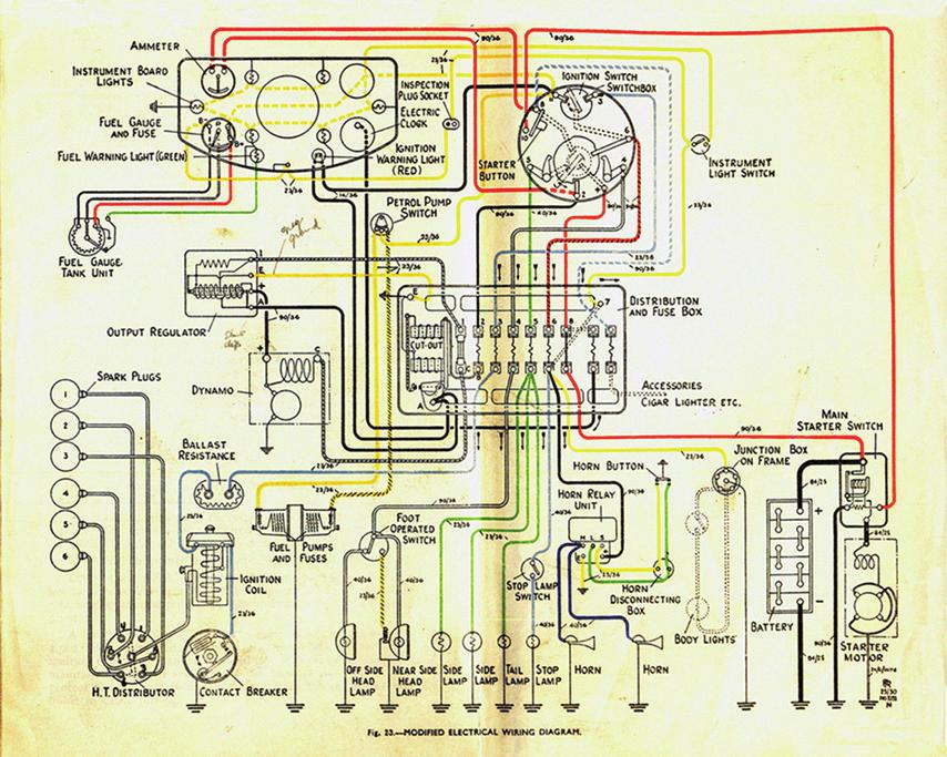
3 50 ROLLS-ROYCE H.P. CAR CHAPTER VII Electrical System General - Battery - Battery Ignition - Sparking Plugs - Electrical Fault Location. General. The equipment comprises a dynamo, distriution box with fuses and automatic cut-out, automatic output regulator, switchbox, ammeter, a 12-volt approximately 60-ampere-hour battery, a starter motor with relay-operated switch, electric horn and fuel gauge, dual electric fuel pumps and battery ignition consisting of non-trembler coil with ballast resistance, and combined low-tension contact breaker and high-tension distributor and the necessary wiring encased in metal tubing. Incorporated with the battery ignition is a governor, which effects automatic control of the battery ignition timing, the effect of the hand control being superimposed. The wiring diagram, Fig. 23, shows the units with their electrical connections, the various wires being indicated in colours to correspond with those of their actual coverings. Battery. The battery recommended for use on this car is either: - Exide XCMRII-IRL or Peto & Radford HZDII-S In climates with air temperatures Filling in acid for first charge Specific Gravity of acid (at 60º F.) Ordinarily below 90º F. (32º C.). Exide P & R Fully charged Exide P & R Frequently above 90º F. (32º C.) ELECTRICAL SYSTEM. 51 Exide. P. & R. First charge current Normal charge current Capacity when fully charged: - Starting for 5 minutes amps. 210 amps. Lighting at 3 amperes hrs. approx. 24 hrs. approx. Voltage across terminals Never allow the liquid in the cells to fall below the tops of the separators. Inspect the battery at regular intevals, and top up with distilled water, so as to maintain the level of the liquid at ½ above the tops of the plates. Do not inspect the battery with the aid of a naked light, and on no account disconnect any of the battery terminals or connections when any charge or discharge current is passing, for such a course incurs risk of explosion and involves personal risk. Battery Ignition. The battery ignition is in a very accessible position, as shown in Fig. 24, and consists of an ignition coil, W, and combined lowtension contact breaker, X, and high-tension distributor, XI. A ballast resistance, RI, is connected in series with the low-tension winding of the coil. Its function is to limit the current taken by the coil at slow speed, or if the ignition switch be accidentally left on while the engine is stopped. It also secures practical equality of intensity of secondary spark at all speeds. A condensor connected across the contact points is located in a pocket, X2, of this apparatus, the condensor case and the main body of the contact breaker unit being together in direct electrical connection with the chassis frame. The insulated terminal of the condensor is connected to the insulated contact, and they are brought out together to the insulated terminal to which the external low-tension connection is made. In setting the points the gap opening should be.015 to.018. Every 5,000 miles, as directed on page 21, the pivot pin of the low-tension rocker arm should be lubricated by moving aside the retaining spring and putting one drop of oil on the exposed end of the pivot Ȧ few drops of oil C should be injected into lubricator, Z, every 2,500 miles, as directed on page 19, in order to lubricate the centrifugal ignition timing mechanism. In addition, the oil so injected serves to maintain an oil seal arranged at the base of the ignition tower to protect the contacts from oily vapour from the crankcase, which is liable to cause pitting.
4

5 52 ROLLS-ROYCE H.P. CAR The high-tension distributor requires no attention beyond an occasional wiping of the interior with a clean, dry rag. It is important that theoutside of the coil casing should be kept clean. Also, the cover should occasionally be removed and the top of the coil cleaned with a dry rag. Misfiring is some times caused by an accumulation of dirt around the terminals and on the coil casing. Fig IGNITION COILS, DISTRIBUTOR AND BALLAST RESISTANCE. ELECTRICAL SYSTEM. 53 If the timing of the battery ignition should have been deranged, due, for instance, to removal of the cam operating the low-tension rocker, it can be re-set by reference to the flywheel markings which can be seen on removal of the clutch pit cover. To carry out this operation, the crankshaft should be turned until the mark B.A.I. (battery, advanced ignition) on the flywheel registers with the mark on the casing when No. I piston is approaching its firing stroke. Owing to the fact that a friction-damped spring drive is used for driving the valve gear and all auxilliaries, and that the starting handle operates to turn the crankshaft through the medium of this spring drive, it is important that the crankshaft be rotated for timimg purposes from the flywheel end. Also, the starting handle should not have been used at all since the engine was last running. Fully advance the ignition lever, and then set the contact breaker cam to be just on the point of causing contact break (when turning forward) corresponding to cylinder No. I. A convenient method of determining precisely when the break takes place is by reference to the ammeter. With the ignition switched on, and someone watching the ammeter, the cam should be slowly rotated on the tape of its shaft in the normal direction of rotation until the required peak breaks contact as indicated by the reading of the ammeter. The screw securing the cam should be tightened. A spare ignition coil is provided as shown at Wr, Fig. 24. It is put into commission by interchanging the high-tension terminals, H and Hr, and changing over the two low-tension leads, one of which is seen at G, from one coil to the other. A small casing on the dashboard, marked Ignition Spares, contains a spare low-tension rocker arm complete with springs and contact point, and also a spare contact screw. Sparking Plugs. Either K.L.G. Type F.L.B. 30X or Champion Type LB.8, 14 m/m sparking plugs are recommended for this car. Plugs should be removed and serviced on special plug cleaning and testing machine, which should be available in all service stations, every 5,000 miles. Reset gaps to.020. Electrical Fault Location. An electric torch hand-lamp should be carried when much night running is being done, in addition to an inspection lamp with a plug which may be connected to the switchbox. In case of faulty operation, proceed to investigate as follows: - I. Failure of any part of the system separately may be due to a blown fuse in the distribution box.
6 54 ROLLS-ROYCE H.P. CAR 2. Failure of incorrect operaton of the system may be due to the fusing of the emergenct battery fuse due to an earth Repeated failure of a properly fitted fuse indicates a fault on the system. If the dynamo does not charge: - 1. Ascertain whether dynamo or regulator is at fault by removing regulator cover and connecting terminal I to E, and terminal A to +. This will short-circuit the regulator. Then, start engine gently and increase speed slowly. If dynamo is in order, the output will be delivered and the defect will lie in the regulator. 2. Dynamo brushes may be sticking, due probably to oiliness. Clean brushes and holders with a rag moistened with petrol. 3. Cut-out contacts may be burnt or sticking. 4. Inspect armature fuse, No. 2, in distibution box. If dynamo oputput is low, this may bedue to battery being fully charged, but if low with lights on, i.e. ammeter indicates an abnormal discharge, the regulator may be sticking in such a manner as permanently to insert the field resistance. If dynamo gives an excessive charge and blows fuse (No. 2), when speeded up, this may be due to regulator sticking or to a break in the regulator shunt coil circuit. Check regulator wiring connections. In the case of defective operation which is traceable to the regulator, the unit must be removed and returned for rectification to Rolls-Royce Ltd. If, with the fuses intact, and the lights in order, the ignition: - (a) Misses (b) Fails. 1. First confirm right condition of sparking plugs. Assure correct condition of contact breaker points, and adjust gap.015 to.018, if necessary. If missing still continues, test ignition circuit as below Dirty ignition coil casing. With battery ignition switched on, see by ammeter, while engine is cranked, that the coil is taking current intermittently. If no current, test availability of battery voltage on ballast resistance terminals then at coil terminals. If, with battery in order, starter motor is sluggish or does not turn, examine commutator and brushes. Clean oily brushes and holders with a rag moistened with petrol. If motor turns without turning engine, examine Bijur drive. If battery will not retain charge: - 1. Ascertain that no circuit is left switched on. 2. See that no cell of the battery leaks acid. Fig GUIDE TO LOCATION OF MAIN SERVICE STATION.
7 Fig GUIDE TO LOCATION OF CREWE SERVICE STATION.
INFORMATION. covering use of Ammeter and Voltmeter ON and 1915 Model Six-54 Electrical System
 INFORMATION covering use of Ammeter and Voltmeter ON- 1914 and 1915 Model Six-54 Electrical System Hudson Motor Car Company Detroit, Michigan, IX S. A USE OF AMMETER ON 1914 AND 1915 MODEL SIX-54 With
Unit AE01K Knowledge of Locating and Correcting Simple Electrical Faults in the Automotive Workplace
 Assessment Requirements Unit AE01K Knowledge of Locating and Correcting Simple Electrical Faults in the Automotive Workplace Content: Basic electrical principles a. Explain the direction of current flow
COOLING AND LUBRICATION SYSTEM
 COOLING AND LUBRICATION SYSTEM 8-1 COOLING AND LUBRICATION SYSTEM CONTENTS ENGINE COOLANT... 8-2 COOLING CIRCUIT... 8-3 COOLING CIRCUIT INSPECTION... 8-3 RADIATOR AND WATER HOSE... 8-4 RADIATOR REMOVAL
Preventive maintenance 4
 00 Series Preventive maintenance Preventive maintenance periods Use the procedures in this chapter to maintain your engine in accordance with the preventive maintenance schedule. Check the periods given
SECTION 3.00 WARNING WARNING ENGINE STARTUP AND SHUTDOWN PRESTART INSPECTION
 SECTION 3.00 ENGINE STARTUP AND SHUTDOWN PRESTART INSPECTION Be sure that the clutch, circuit breaker, or other main power transmission device is disconnected. Generators develop voltage as soon as the
AIR COMPRESSOR OPERATING INSTRUCTION AND PARTS LIST
 AIR COMPRESSOR OPERATING INSTRUCTION AND PARTS LIST BELT TYPE IMPORTANT PLEASE MAKE CERTAIN THAT THE PERSON WHO IS TO USE THIS EQUIPMENT CAREFULLY READS AND UNDERSTANDS THESE INSTRUCTIONS BEFORE STARTING
WORKSHOP MANUAL ELECTRICITY
 WORKSHOP MANUAL ELECTRICITY GB reference : 754282 DC/ATR 04/2000 1. Electric units:...2 2. Key formulae to remember:...2 3. Definitions:...3 4. Elements:...4 Resistances:...4 Lights:...5 Condensers:...5
Battery Operation. Battery Construction. Battery State Of Charge. Battery Load Test. Battery Rating Systems 2/14/12
 Battery Operation Batteries, Charging and Donald Jones Brookhaven College Batteries convert chemical energy into electrical energy During discharge the battery s plate composition is changed During charging
Electrical Equipment-Maintenance Instructions
 MODEL: SERIES "E" EIGHT No. OF SHEETS 21 SHEET NO. 1 Electrical Equipment-Maintenance Instructions DYNAMO Compensated Voltage Control Types Compensated voltage control type dynamos operate in conjunction
Periodic Lubrication and Attention
 PERIODIC LUBRICATION AND ATTENTION. 13 CHAPTER II Periodic Lubrication and Attention LUBRICANTS RECOMMENDED Rolls-Royce Limited recommend a first quality oil of viscosity S.A.E. 30 for the engine and gearbox
ENGINE COOLING Click on the applicable bookmark to selected the required model year
 ENGINE COOLING - ENGINE COOLING General Information/ Service Specifications/Lubricant/Sealants GENERAL INFORMATION 0000 The cooling system is designed to keep every part of the engine at appropriate temperature
CHAPTER 20: Operation and maintenance
 Pressurized Irrigation Techniques 20.1 CHAPTER 20: Operation and maintenance INTRODUCTION The efficient operation of an irrigation system depends mainly on the ability of the farmer to make the best use
Unit AE06K Knowledge of Diagnosis and Rectification of Vehicle Auxiliary Electrical Faults
 Assessment Requirements Unit AE06K Knowledge of Diagnosis and Rectification of Vehicle Auxiliary Electrical Faults Content: The electrical principles that are related to light vehicle electrical circuits:
Light condition and operation Windshield glass condition Wiper blade condition Paint condition and corrosion Fluid leaks Door and hood lock condition
 GENERAL CHECKS Engine Compartment The following should be checked regularly: Engine oil level and condition Transmission fluid level and condition Brake fluid level Clutch fluid level Engine coolant level
Chapter 5 Part B: Ignition system - transistorised type
 5B 1 Chapter 5 Part B: Ignition system - transistorised type Contents Coil - testing........................................... 9 Distributor - overhaul..................................... 7 Distributor
720W PORTABLE GENERATOR
 720W PORTABLE GENERATOR MODEL NO: G720 PART NO: 8857800 OPERATION & MAINTENANCE INSTRUCTIONS LS0214 INTRODUCTION Thank you for purchasing this CLARKE 720W Portable Generator Before attempting to use this
SECTION 9 CRANKING SYSTEM CONTENTS
 SECTION 9 CRANKING SYSTEM CONTENTS 9-1. 9-2. 9-3. 9-4. 9-5. 9-6. 9-7. 9-8. GENERAL DESCRIPTION.,...,..., 9-2 SPECIFICATIONS.......................................... 9-4 LUBRICATION 9-5 REMOVAL AND INSTALLATION...
GENERAL SPECIFICATIONS 25-2 GENERAL. Water cooling, forced circulation with electric fan
 COOLING SYSTEM GENERAL 2 COOLING SySTEM 8 RADIATOR 10 RADIATOR FAN MOTOR ASSY 12 WATER PUMP 14 THERMOSTAT 16 WATER HOSE AND PiPE 17 WATER TEMPERATURE GAUGE UNIT AND SENSOR 18 GENERAL GENERAL Y25CAOA SPECIFICATIONS
A SYSTEMATIC SEQUENCE FOR PM INSPECTIONS
 A SYSTEMATIC SEQUENCE FOR PM INSPECTIONS TYPE OF INSPECTION UNDER THE HOOD GASOLINE AND DIESEL 1 Fuel, oil, exhaust leaks - inspect 2 Oil and fuel lines inspect for kinks and wear 3 Automatic transmission
1 THE WOLVERTON SYSTEM OF TRAIN LIGHTING.
 1 THE WOLVERTON SYSTEM OF TRAIN LIGHTING. The Wolverton equipment is a single battery system utilising a plain shunt wound dynamo. The dynamo is controlled by an automatic field regulator which senses
COOLING SYSTEM. Return to Main Table of Contents
 COOLING SYSTEM Return to Main Table of Contents GENERAL... 2 COOLING SYSTEM... 7 RADIATOR... 9 ENGINE COOLANT PUMP... 12 THERMOSTAT... 14 ENGINE COOLANT TEMPERATURE SENDER &, SENSOR... 15 ENGINE COOLANT
SERVICING SPECIFICATIONS (1) ENGINE BODY
 ENGINE BODY") SERVICING SPECIFICATIONS (1) ENGINE BODY (1/14) Lubricating oil capacity Cylinder head surface Oil pan depth 121 mm (4.76 in.) Oil pan depth 101 mm (3.98 in.) 2.5 L 0.66 U.S.gals. 0.55 lmp.gals. 3.8 L
SERVICING SPECIFICATIONS (1) ENGINE BODY (1/14) Lubricating oil capacity Cylinder head surface Oil pan depth 121 mm (4.76 in.) Oil pan depth 101 mm (3.98 in.) 2.5 L 0.66 U.S.gals. 0.55 lmp.gals. 3.8 L
Unit D: Agricultural Equipment Systems. Lesson 1: Understanding Applications of Fluids and Lubricants in Agricultural Equipment
 Unit D: Agricultural Equipment Systems Lesson 1: Understanding Applications of Fluids and Lubricants in Agricultural Equipment 1 Terms Ash content bottom dead center cloud point compression ratio coolant
Chapter 3 Ignition system For modifications, and information applicable to later models, see Supplement at end of manual
 Chapter 3 Ignition system For modifications, and information applicable to later models, see Supplement at end of manual Condenser (capacitor) - description, removal and refitting 6 Contact breaker points
Starting and Charging
 The Starting and Charging System is a critical system in your vehicle. The Starting system provides the ability to crank the engine electrically from the drivers position. The first car with electric starting
5-2 FUEL SYSTEM AND THROTTLE BODY FUEL SYSTEM FUEL DELIVERY SYSTEM The fuel delivery system consists of the fuel tank, fuel pump, fuel filters, fuel f
 FUEL SYSTEM AND THROTTLE BODY 5-1 FUEL SYSTEM AND THROTTLE BODY I CONTENTS FUEL SYSTEM 5-2 FUEL DELIVERY SYSTEM 5-2 FUEL PUMP 5-3 FUEL PRESSURE REGULATOR 5-4 FUEL INJECTOR 5-4 FUEL PUMP CONTROL SYSTEM
John Deere. MODEL: 2030 Tractor JD-O-OMR50675
 John Deere MODEL: 2030 Tractor THIS IS A MANUAL PRODUCED BY JENSALES INC. WITHOUT THE AUTHORIZATION OF JOHN DEERE OR IT'S SUCCESSORS. JOHN DEERE AND IT'S SUCCESSORS ARE NOT RESPONSIBLE FOR THE QUALITY
ELECTRICAL SYSTEM CONTENTS LOCATION OF ELECTRICAL COMPONENTS 5-1 IGNITION SYSTEM 5-3 CHARGING SYSTEM 5-7
 ELECTRICAL SYSTEM CONTENTS LOCATION OF ELECTRICAL COMPONENTS 5-1 IGNITION SYSTEM 5-3 CHARGING SYSTEM 5-7 STARTER SYSTEM AND SIDE STAND IGNITION INTERLOCK SYSTEM 5-11 SWITCHES 5-15 LAMP 5-16 BATTERY 5-18
SPECIFICATIONS TEST AND ADJUSTMENT SPECIFICATIONS SPECIFICATIONS ENGINE FD620D, K SERIES
 TEST AND ADJUSTMENT Engine Oil Pressure Sensor Activates............................... 98 kpa (14.2 psi) Oil Pressure While Cranking (Minimum).......................... 28 kpa (4 psi) Oil Pressure.....................................
John Deere. MODEL: 4620 Tractor JD-S-TM1030
 John Deere MODEL: 4620 Tractor THIS IS A MANUAL PRODUCED BY JENSALES INC. WITHOUT THE AUTHORIZATION OF JOHN DEERE OR IT'S SUCCESSORS. JOHN DEERE AND IT'S SUCCESSORS ARE NOT RESPONSIBLE FOR THE QUALITY
SERVICING SPECIFICATIONS (1) ENGINE BODY
 ENGINE BODY") SERVICING SPECIFICATIONS (1) ENGINE BODY Lubricating oil capacity Oil pan depth 110 mm (4.33 in.) 5.7 L 1.5 U.S.gals (1/14) Oil pan depth 125 mm (4.92 in.) 5.1 L 1.3 U.S.gals Oil pan depth 130 mm (5.12
SERVICING SPECIFICATIONS (1) ENGINE BODY Lubricating oil capacity Oil pan depth 110 mm (4.33 in.) 5.7 L 1.5 U.S.gals (1/14) Oil pan depth 125 mm (4.92 in.) 5.1 L 1.3 U.S.gals Oil pan depth 130 mm (5.12
February 26, ch.12.notebook. Ch. 12. Preventative Maintenance and Troubleshooting. Feb 23 5:03 PM
 Ch. 12 Preventative Maintenance and Troubleshooting Feb 23 5:03 PM 1 Why PM? preventive maintenance certain maintenance tasks must be performed regularly to keep an engine working properly helps premature
1950 Pacemaker. Specifications & Adjustments
 Specifications & Adjustments Specifications & Adjustments ENGINE: Valve Arrangement Bore and Stroke Piston Displacement Maximum Torque Horsepower Actual Taxable Compression Ratio: Cast Iron Head (Std.)
9.7 Replacement of the compressed air distributor
 9.6.6 9.6.7 screw in the bolt and to increase unscrew the bolt. For a complete rotation of the bolt, the variation is of 1mm. After measuring the pointer position and the compensatory adjustment screw
STARTING SYSTEM (1ZZ FE) (April, 2003)
 (April, 2003)") STARTING & CHARGING STARTING SYSTEM (1ZZ FE) (April, 2003) STARTING SYSTEM (1ZZ FE) (April, 2003) INSPECTION 19 1 190QO 02 1. INSPECT STARTER ASSY NOTICE: These tests must be performed within 3 to 5 seconds
STARTING & CHARGING STARTING SYSTEM (1ZZ FE) (April, 2003) STARTING SYSTEM (1ZZ FE) (April, 2003) INSPECTION 19 1 190QO 02 1. INSPECT STARTER ASSY NOTICE: These tests must be performed within 3 to 5 seconds
CHAPTER 6 IGNITION SYSTEM
 CHAPTER 6 CHAPTER 6 IGNITION SYSTEM CONTENTS PAGE Faraday s Law 02 The magneto System 04 Dynamo/Alternator System 06 Distributor 08 Electronic System 10 Spark Plugs 12 IGNITION SYSTEM Faraday s Law The
66 CHAPTER FOUR. Spark Plug Removal Refer to Figure 28 for spark plug wive routing according to engine.
 66 CHAPTER FOUR IGNITION SYSTEM A mechanical contact breaker point ignition system is used on all engines covered in this manual. The ignition system may use a Delco-Remy, Autolite, Mallory or Prestolite
EC Off Season Care of Irrigation Equipment
 University of Nebraska - Lincoln DigitalCommons@University of Nebraska - Lincoln Historical Materials from University of Nebraska- Lincoln Extension Extension 1964 EC64-729 Off Season Care of Irrigation
SECTION M. ELECTRICAL. Section Description Page No.
 SECTION M. ELECTRICAL. Section Description Page No. M.1 General Page 2 M.2 Alternator Page 2 M.3 Battery Page 7 M.4 Hazard Warning System Page 7 M.5 Brake Fail Warning System Page 8 M.6 Seat Belt Warning
IMPORTANT INFORMATION
 Table of Contents IMPORTANT INFORMATION Section 1B - Maintenance MAINTENANCE 1 B Specifications................................ 1B-1 Special Tools................................ 1B-2 Quicksilver Lubricant/Sealant..................
CHAPTER 10 ELECTRIC SYSTEM
 CHAPTER 10 ELECTRIC SYSTEM 1. ELECTRIC SYSTEM ELECTRIC SYSTEM 1.1 WIRING DIAGRAM CK20-USA 196WA00A S196-WOO Jul. 2003 10-3 CK20(M) CHAPTER 10 CK20-EU 196WA51A 10-4 S196-WOO Jul. 2003 ELECTRIC SYSTEM 1.2
STARTING & CHARGING SYSTEM
 K ELECTRICAL SECTION SC A STARTING & CHARGING SYSTEM B C D CONTENTS E PRECAUTIONS... 2 Precautions for Supplemental Restraint System (SRS) AIR BAG and SEAT BELT PRE-TEN- SIONER... 2 Precautions for Power
MANUAL CONTROL / SEMIAUTO TEMPERATURE CONTROL HEATING, VENTILATION AND AIR CONDITIONING SYSTEM
 SECTION 7C MANUAL CONTROL / SEMIAUTO TEMPERATURE CONTROL HEATING, VENTILATION AND AIR CONDITIONING SYSTEM CAUTION: Disconnect the negative battery cable before removing or installing any electrical unit
UNIVERSAL ATOMIC DIESEL MODEL (16 H.P.) PARTS MANUAL. Universal Motors
 PARTS MANUAL. Universal Motors") UNIVERSAL ATOMIC DIESEL MODEL 20 5416 (16 H.P.) PARTS MANUAL Universal Motors This copy of the Universal Motors Owners Manual has been re-created using images computer scanned from a manual rather than
UNIVERSAL ATOMIC DIESEL MODEL 20 5416 (16 H.P.) PARTS MANUAL Universal Motors This copy of the Universal Motors Owners Manual has been re-created using images computer scanned from a manual rather than
Chapter 5 Part B: Ignition system
 5B 1 Chapter 5 Part B: Ignition system Contents Distributor - removal and refitting.............................4 Ignition HT coil(s) - removal, testing and refitting.................3 Ignition system
John Deere. MODEL: 4230 Tractor Volume 1 of 2 JD-S-TM1056
 John Deere MODEL: 4230 Tractor Volume 1 of 2 THIS IS A MANUAL PRODUCED BY JENSALES INC. WITHOUT THE AUTHORIZATION OF JOHN DEERE OR IT'S SUCCESSORS. JOHN DEERE AND IT'S SUCCESSORS ARE NOT RESPONSIBLE FOR
Engine Does Not Start or Is Hard to Start Cause of Trouble. 1. Open the drain screw, and check Fuel not supplied (1) Fuel tank empty
 Fuel tank empty") 20. Engine Does Not Start or Is Hard to Start 20-1 Engine Output Insufficient 20-2 Poor Performance at Low Speed and Idling 20-3 Poor Performance at High Speed 20-3 Unsatisfactory Operation 20-4 Fuel Gauge
20. Engine Does Not Start or Is Hard to Start 20-1 Engine Output Insufficient 20-2 Poor Performance at Low Speed and Idling 20-3 Poor Performance at High Speed 20-3 Unsatisfactory Operation 20-4 Fuel Gauge
SPECIFICATIONS TEST AND ADJUSTMENT SPECIFICATIONS SPECIFICATIONS ENGINE FD620D, K SERIES
 ENGINE FD620D, K SERIES SPECIFICATIONS SPECIFICATIONS TEST AND ADJUSTMENT SPECIFICATIONS Engine Oil Pressure Sensor Activates............................... 98 kpa (14.2 psi) Oil Pressure While Cranking
14-6. TSB Revision ENGINE COOLING ON-VEHICLE SERVICE
 14-6 RADIATOR CAP DRAIN PLUG ENGINE COOLING ON-VEHICLE SERVICE When removing the radiator cap, use care to avoid contact with hot coolant or steam Place a shop towel over the cap and turn the cap counterclockwise
STARTING & CHARGING SYSTEM SECTIONSC CONTENTS IDX
 STARTING & CHARGING SYSTEM SECTIONSC GI MA EM LC EC CONTENTS FE PRECAUTIONS...2 Supplemental Restraint System (SRS) AIR BAG and SEAT BELT PRE-TENSIONER...2 Wiring Diagrams and Trouble Diagnosis...2 BATTERY...3
1984 Jeep CJ7. IGNITION SYSTEM - SOLID STATE' 'Distributors & Ignition Systems MOTORCRAFT SOLID STATE IGNITION (SSI)
") TESTING SECONDARY CIRCUIT CHECK CAUTION: When checking secondary voltage, do not remove spark plug wires from spark plugs No. 3 on 4-cylinder, No. 1 or 5 on 6-cylinder and No. 3 or 4 on V8 Engines. 1.
TESTING SECONDARY CIRCUIT CHECK CAUTION: When checking secondary voltage, do not remove spark plug wires from spark plugs No. 3 on 4-cylinder, No. 1 or 5 on 6-cylinder and No. 3 or 4 on V8 Engines. 1.
 1 of 16 1/10/2015 7:25 AM STARTER MOTOR 2009 Hyundai Accent 1.6L Eng GS REQUESTED INFORMATION DISASSEMBLY 1. Disconnect the M-terminal (A) on the magnet switch assembly (B). Fig 1: Identifying M-Terminal
INSTRUCTIONS. Delco Systems
 INSTRUCTIONS FOR THE CARE OF 6-24 Delco Systems The Dayton Engineering Laboratories Co. Dayton, Ohio This is a description of the 6-24 volt system as applied to the following cars: 1912 Cadillac 1913 Cole
SECTION 1E ENGINE ELECTRICAL
 SECTION 1E ENGINE ELECTRICAL CAUTION: Disconnect the negative battery cable before removing or installing any electrical unit or when a tool or equipment could easily come in contact with exposed electrical
Objectives Topics Resources & Notes GAIN ATTENTION Review homework from Chapter 2 Slide 1 OBJECTIVE
 3 Inboard Spark Engines - Part 2 29 COURSE LESSON TITLE Chapter 3 Inboard Spark Engines Part 2 PRESENTATION TIME PRESENTATION METHOD MATERIALS REQUIRED 2 hours Participative Lecture Ch3 PPT slides, computer,
Chapter 4 Ignition & Electrical Systems
 Chapter 4 Ignition & Electrical Systems Chapter 4 Section A Study Aid Questions Fill in the Blanks 1. Ignition systems can be divided into two classifications: systems or systems for reciprocating engines.
RPM Inductive XENON TIMING LIGHT
 RPM Inductive XENON TIMING LIGHT PART NO G4132 HANDBOOK RPM Inductive INDEX Page 1. XENON TIMING LIGHT 2 2. PRINCIPLE OF OPERATION 2 3. IMPORTANCE OF IGNITION TIMING 3 4. USE OF UNLEADED PETROL 3 5. TIMESTROBE
AccuSpark. Fitting and Information Guide For. Modules Distributors coils Tools. Modern Ignition for Classic cars
 AccuSpark Modern Ignition for Classic cars Fitting and Information Guide For Modules Distributors coils Tools www.accuspark.co.uk 1 Before fitting AccuSpark Distributors AccuSpark electronic ignition kit.
SERVICING SPECIFICATIONS (1) ENGINE BODY
 ENGINE BODY") SERVICING SPECIFICATIONS (1) ENGINE BODY (1/14) Lubricating oil capacity Oil pan depth 124 mm (4.88 in.) 7.0 L 1.85 U.S.gals. 1.54 lmp.gals. 9.5 L 2.51 U.S.gals. 2.09 lmp.gals. Oil pan depth 90 mm (3.54
SERVICING SPECIFICATIONS (1) ENGINE BODY (1/14) Lubricating oil capacity Oil pan depth 124 mm (4.88 in.) 7.0 L 1.85 U.S.gals. 1.54 lmp.gals. 9.5 L 2.51 U.S.gals. 2.09 lmp.gals. Oil pan depth 90 mm (3.54
Liquid Cooled Diesel Engine
 Chapter 4 Liquid Cooled Diesel Engine Table of Contents GENERAL INFORMATION................... 2 SPECIFICATIONS.......................... 3 General................................ 4 Engine.................................
Maintenance of Pleasureboat Diesel Engine GM Series
 Maintenance of Pleasureboat Diesel Engine GM Series.Safety Precaution for Inspection )Battery Fluid Battery fluid is diluted sulfuric acid. It can blind you if it gets in your eyes, or burn your skin.
Tips & Technology For Bosch business partners
 Tips & Technology For Bosch business partners Current topics for successful workshops No. 05 Trucks Starters and starter systems Part 2 Moderately heavy commercial vehicles with diesel engines having a
DESCRIPTION & OPERATION
 DESCRIPTION & OPERATION 1999-2000 STARTING & CHARGING SYSTEMS Generators & Regulators NOTE: This article also applies to Lexus LX470. For Lexus LX470, refer to Land Cruiser, unless otherwise indicated.
Oil Pump Removal and Installation
 E-2 Engine Lubrication System: Oil Gallery Jet Inspect the oil gallery jet for clogging. Clean the oil gallery if necessary. 6) Remove the O-ring (6) and dowel pins. 6 I837H50033-0 Oil Pump Removal and
CHARGING SYSTEM CHARGING SYSTEM CH 1
 CH1 CH2 Precautions PRECAUTIONS 1. Check that the battery cables are connected to the correct terminals. 2. Disconnect the battery cables when the battery is given a quick charge. 3. Do not perform tests
CHASSIS CONTENTS EXTERIOR PARTS 7-1 FRONT WHEEL 7-2 FRONT BRAKE 7-6 HANDLEBARS 7-13 FRONT FORK 7-15 STEERING 7-23 REAR WHEEL 7-26 REAR BRAKE 7-30
 CHASSIS CONTENTS EXTERIOR PARTS 7- FRONT WHEEL 7-2 FRONT BRAKE 7-6 HANDLEBARS 7-3 FRONT FORK 7-5 STEERING 7-23 REAR WHEEL 7-26 REAR BRAKE 7-30 REAR SHOCK ABSORBER 7-32 SWING ARM 7-33 7 7- CHASSIS EXTERIOR
Table No. 1 provides a means of identifying the various alternator systems. Note: All output figures are rated at 3600 RPM. TABLE NO.
 The alternator systems installed on Briggs & Stratton Intek OHV-Twin Cylinder Engines can easily be identified by the color of the stator output wires and the connector. Table No. 1 provides a means of
TUNE UP EG2 12 ENGINE MECHANICAL
 EG212 TUNEUP 1. CHECK COOLANT LEVEL AT RESERVOIR TANK The engine coolant level should be between the LOW and FULL lines. If low, check for leaks and add engine coolant up to the FULL line. 2. CHECK COOLANT
TUNE-UP - 4-CYL Jeep Cherokee IDENTIFICATION ENGINE IDENTIFICATION TUNE-UP NOTES TESTING ENGINE COMPRESSION SPARK PLUGS
 TUNE-UP - 4-CYL 1988 Jeep Cherokee 1988 Jeep 4 Tune-Up TUNE-UP All Models IDENTIFICATION ENGINE IDENTIFICATION Engine can be identified by the 4th character of the Vehicle Identification Number (VIN).
Page 1 of 1 ALTERNATORS. Overview. Intek TM V-Twin Cylinder OHV Engine Service Manual Version 1.0. Copyright 1999 by Briggs and Stratton Corporation
 Overview Alternator Identification Page 1 of 3 The alternator systems installed on Briggs & Stratton Intek V-Twin Cylinder OHV Engines can easily be identified by the color of the stator output wires and
TC Series Cooling Systems
 TC Series Cooling Systems Table of Contents Table of Contents...1 List of Figures...1 Safety...2 Introduction...2 General Specifications...2 Types of Coolant...2 Routine Maintenance...2 Surge Tank Coolant
BATTERY CHARGER-STARTER
 BATTERY CHARGER-STARTER MODEL NO: WBC240 & WBC400 PART NO: 6261505 & 6261515 OPERATION & MAINTENANCE INSTRUCTIONS GC0116 INTRODUCTION Thank you for purchasing this CLARKE Battery Charger/Starter. Please
Tri-Spark Ignition System Installation Triple Cylinder TRI-0001
 Tri-Spark Ignition System Installation Triple Cylinder TRI-0001 There are potentially lethal high voltages produced at the ignition coils and spark plugs, therefore every precaution must be taken to prevent
REMOVAL & INSTALLATION
 REMOVAL & INSTALLATION TIMING BELT Removal 1. Disconnect negative battery cable. Rotate engine clockwise and position cylinder No. 1 on TDC of compression stroke. Ensure "O" mark on crankshaft pulley aligns
KUBOTA WATER-COOLED DIESEL ENGINE
 SPARE PARTS CATALOGUE KUBOTA WATER-COOLED DIESEL ENGINE MODEL: E75N E75NB3 0001 010 14418-0101-0 Crankcase Compl. 1 1 0001 020 14971-2671-0 Plug, Seal 2 2 0001 030 14301-3363-0 Pin Plug 2 2 0001 040 05012-00612
TUNE-UP - 6-CYL Jeep Cherokee IDENTIFICATION ENGINE IDENTIFICATION TUNE-UP NOTES TESTING ENGINE COMPRESSION HIGH TENSION WIRE RESISTANCE
 TUNE-UP - 6-CYL 1988 Jeep Cherokee 1987-88 TUNE-UP Jeep 6 Cylinder Tune-Up Cherokee, Comanche, Wagoneer, Wrangler IDENTIFICATION ENGINE IDENTIFICATION Engine can be identified by the fourth character of
MINE CHARGER INSTALLATION AND OPERATION MANUAL MODEL NUMBERS: MSP MSQ MSR MSS
 MINE CHARGER INSTALLATION AND OPERATION MANUAL MODEL NUMBERS: MSP MSQ MSR MSS Sec# Table of Contents Pg# 1 INSTALLATION 1.1 Receiving 1 1.2 Location 1 1.3 Line Voltage Adjustments 2 1.4 A.C. Service Requirements
SECTION 8 2 DO IT YOURSELF MAINTENANCE. Chassis
 DO IT YOURSELF MAINTENANCE Chassis SECTION 8 2 Checking the coolant level of the traction motor................ 184 Checking the radiator....................................... 185 Checking brake fluid........................................
Hillman Minx Maintenance Schedule
 Hillman Minx Maintenance Schedule The maintenance schedule for most Series Minxes can be found as a large fold-out sheet, pasted inside the back cover of the Owner's Handbook. Series V and VI have a much
A. Perform a vacuum gauge test to determine engine condition and performance.
 ENGINE REPAIR UNIT 2: ENGINE DIAGNOSIS, REMOVAL, AND INSTALLATION LESSON 2: ENGINE DIAGNOSTIC TESTS NOTE: Testing the engine s mechanical condition is required when the cause of a problem is not located
SP6. Automatic Battery Charger. Model
 Model SP6 Automatic Battery Charger OWNERS MANUAL PLEASE SAVE THIS OWNERS MANUAL AND READ BEFORE EACH USE. This manual will explain how to use the charger safely and effectively. Please read and follow
A/C-HEATER SYSTEM - AUTOMATIC
 A/C-HEATER SYSTEM - AUTOMATIC 1988 Toyota Celica 1988 Automatic A/C-Heater Systems Celica * PLEASE READ THIS FIRST * CAUTION: When discharging air conditioning system, use only approved refrigerant recovery/recycling
STARTING/CHARGING SYSTEMS Brought to you by Eris Studios NOT FOR RESALE
 STARTING/CHARGING SYSTEMS General Description 1. General Description A: SPECIFICATION Vehicle model Starter Generator Item Specification Type Reduction type Model 428000-5760 Manufacturer DENSO Voltage
HOFFMANN POWER PRODUCTS PARTS LIST 2014
 HOFFMANN POWER PRODUCTS PARTS LIST 2014 VIBRATORY PLATE COMPACTOR ALL PARTS ARE SUBJECT TO STANDARD HOFFMANN TERMS AND CONDITIONS OF SALE 2010 Replacement parts are not manufactured, sold or warranted
CHAPTER 8 ELECTRICAL. CHAPTER 8 ELECTRICAL ATV SERVICE MANUAL 2005/ version number WIRING DIAGRAM 8.2 PARTS INSPECTION AND SERVICE
 CHAPTER 8 ELECTRICAL ATV SERVICE MANUAL 2005/ version number 0501 CHAPTER 8 ELECTRICAL 8.1 WIRING DIAGRAM 8.2 PARTS INSPECTION AND SERVICE 8.3 BATTERY 8.4 IGNITION SYSTEM 8.5 CHARGING SYSTEM 8.6 ELECTRICS
ELECTRICAL SYSTEM CONTENTS LOCATION OF ELECTRICAL COMPONENTS 5-1 IGNITION SYSTEM 5-3 CHARGING SYSTEM 5-7
 ELECTRICAL SYSTEM CONTENTS LOCATION OF ELECTRICAL COMPONENTS 5- IGNITION SYSTEM 5-3 CHARGING SYSTEM 5-7 STARTER SYSTEM AND SIDE STAND 5- IGNITION INTERLOCK SYSTEM SWITCHES 5-5 LAMP 5-6 BATTERY 5-8 5 FUEL
ON-VEHICLE INSPECTION
 CH2 P11586 CHARGING CHARGING SYSTEM ONVEHICLE INSPECTION 1. CHECK BATTERY ELECTROLYTE LEVEL Check the electrolyte quantity of each cell. MaintenanceFree Battery: CH03L01 If under the lower level, replace
Petrol Driven Water Pump. Model No. CD1-1 Part No OPERATING & MAINTENANCE INSTRUCTIONS
 Petrol Driven Water Pump Model No. CD1-1 Part No. 7230034 OPERATING & MAINTENANCE INSTRUCTIONS Thank you for purchasing this Clarke CD1 petrol driven water pump. Before attempting to operate this pump
John Deere. MODEL: 2020 Tractor. SIn 117,500 & Up JD-S-TM1044
 John Deere MODEL: 2020 Tractor SIn 117,500 & Up THIS IS A MANUAL PRODUCED BY JENSALES INC. WITHOUT THE AUTHORIZATION OF JOHN DEERE OR IT'S SUCCESSORS. JOHN DEERE AND IT'S SUCCESSORS ARE NOT RESPONSIBLE
ENGINE COOLING SECTION GENERAL DESCRIPTION / 1 ENGINE COOLING. Figure 1 - Cooling System Flow
 SECTION 09-302.03 09-302.03/ 1 2006JA26 1. COOLANT INLET FROM RADIATOR 2. WATER PUMP SUCTION 3. COOLANT FILTER INLET 4. COOLANT FILTER OUTLET 5. COOLANT SUPPLY TO CYLINDER HEAD 6. COOLANT RETURN FROM CYLINDER
6 cylinder turbocharged diesel engines for industrial applications
 Perkins Model 2806C-E16 USER S HANDBOOK 6 cylinder turbocharged diesel engines for industrial applications Publication TSD 39E, issue 2. Proprietary information of Perkins Engines Company Limited, all
2008 Toyota RAV ELECTRICAL Charging (2AZ-FE) - RAV4
 - RAV4") 2008 ELECTRICAL Charging (2AZ-FE) - RAV4 CHARGING SYSTEM PRECAUTION 1. Check that the battery cables are connected to the correct terminals. 2. Disconnect the battery cables if a quick charge is given
2008 ELECTRICAL Charging (2AZ-FE) - RAV4 CHARGING SYSTEM PRECAUTION 1. Check that the battery cables are connected to the correct terminals. 2. Disconnect the battery cables if a quick charge is given
1983 BMW 320i. 1.8L 4-CYL 1983 Engines - 1.8L 4-Cylinder Engines - 1.8L 4-Cylinder
 ENGINE IDENTIFICATION 1.8L 4-CYL 1983 Engines - 1.8L 4-Cylinder For engine repair procedures not covered in this article, see ENGINE OVERHAUL PROCEDURES - GENERAL INFORMATION article in the GENERAL INFORMATION
SECTION C. THE IGNITION EQUIPMENT (I~ and 2~ LITRE)
") General SECTION C THE IGNITION EQUIPMENT (I~ and 2~ LITRE) Description. Section No. C.l Section No. C.2 Section No. C.3 Section No. C.4 Section No. C.5 Section No. C.6 Section No. C.7 Section No. C.8 Section
General SECTION C THE IGNITION EQUIPMENT (I~ and 2~ LITRE) Description. Section No. C.l Section No. C.2 Section No. C.3 Section No. C.4 Section No. C.5 Section No. C.6 Section No. C.7 Section No. C.8 Section
EDUCATIONAL SERVICES LTD
 EDUCATIONAL SERVICES LTD Accredited and registered provider Unit Standard: AURTTC2001 2 1. Please circle T or F to indicate whether each of the following statements is true or false: T F Heat always flows
FREE $15 Gift Card for every $100 spent on Ship To Home orders. Find Out How
 1 of 29 10/12/2011 5:05 PM FREE $15 Gift Card for every $100 spent on Ship To Home orders. Find Out How Ford Ranger/Explorer/Mountaineer 1991-1999 Intake Manifold REMOVAL & INSTALLATION Print The engines
Electrical System. Table of Contents ELECTRICAL SYSTEM 15-1
 ELECTRICAL SYSTEM 15-1 Electrical System Table of Contents Exploded View... 15-2 Specifications... 15-6 Special Tools and Sealant... 15-7 Wiring Diagram... 15-8 Precautions... 15-12 Electrical Wiring...
2014 Dodge Challenger R/T. The water pump (1) is mounted directly to the timing chain cover and is equipped with a non serviceable integral pulley.
 is mounted directly to the timing chain cover and is equipped with a non serviceable integral pulley.") Fig. 73: Water Pump A centrifugal water pump (2) circulates coolant through the water jackets, passages, intake manifold, radiator core, cooling system hoses and heater core. The pump is driven from the
Fig. 73: Water Pump A centrifugal water pump (2) circulates coolant through the water jackets, passages, intake manifold, radiator core, cooling system hoses and heater core. The pump is driven from the
Cooling System. Table of Contents
 Sub-Headings Safety 2 s 2 Cautions 2 Notes 2 Introduction 2 General Specifications 2 Engine 2 Coolant 2 Routine Maintenance 2 Hose Connections 4 Radiator, Charge Air and Heater Cores 4 Cooling System Leaks
WARNING: Read these instructions before using the machine GENERATOR MODEL NO: IG3500F PART NO: OPERATION & MAINTENANCE INSTRUCTIONS
 WARNING: Read these instructions before using the machine GENERATOR MODEL NO: IG3500F PART NO: 8877100 OPERATION & MAINTENANCE INSTRUCTIONS ORIGINAL INSTRUCTIONS LS0217 INTRODUCTION Thank you for purchasing