MANUAL PCE-IT111
|
|
|
- Howard Jackson
- 5 years ago
- Views:
Transcription
 191 377 3398 Fax: +44 ( 0 ) 191 377 3357 http://www.industrial-needs.")
1 Tursdale Technical Services Ltd Unit N12B Tursdale Business Park Co. Durham DH6 5PG United Kingdom Phone: +44 ( 0 ) Fax: +44 ( 0 ) MANUAL PCE-IT111
2 TABLE OF CONTENTS SAFETY RULES... 3 SAFETY CHECK... 3 GENERAL DESCRIPTION... 4 BRIEF PRODUCT DESCRIPTION... 5 FEATURES... 5 PRE-TESTING SAFETY... 7 OPERATING INSTRUCTIONS... 7 INSIDE LID INSTRUCTIONS... 8 VERY IMPORTANT AUTOMATIC FEATURES FEATURES COMPARISON PRINCIPLE OF HOW THEY WORK-DISPLAYS-RESULTS PREPARATION FOR USE REPLACE BATTERIES DISPOSING OF BATTERIES FUSES REPLACEMENT SPECIFICATIONS LIMITED WARRANTY... 15

3 SAFETY RULES CAUTION RISK OF ELECTRIC SHOCK This tester has been designed with your safety in mind. However, no design can completely protect against incorrect use. Electrical circuits can be dangerous and/or lethal when lack of caution or poor safety practices is used. Do not carry out field measurements on either the power system grounding, during periods of forecast lightning activity, in areas that encompass the station being measured or of the power network connected to the station being measured. In the event that lightning occurs, stop all testing and isolate any temporarily installed test spikes. Preparations for testing of power system grounding can leave personnel vulnerable to exposure caused by faults at or fed from the system under test, transferred potentials from remote test grounds, and inadvertent line energisations. While the probability of the occurrence of one of these events is low, personnel safety will, nevertheless, be enhanced by the following: When working near high tension systems rubber gloves and shoes should be worn. Work on clean, dry crushed rock or an insulating blanket. Avoid bare hand to hand contact between the tester and extended test leads. When using the tester with test leads, ensure that they are safe and properly authorized Disconnect the tester from any external circuit when checking or changing the Fuse and/or batteries. CAUTION READ THE MANUAL Follow the instructions in the Manual for every measurement. Read and understand the general instructions before attempting to use this tester. SAFETY CHECK Before using the tester check the condition of the test leads and the fuses. The test leads must be free of cracks or any damages and must be insulated as when they were new. Fuse replacement is described later in this user's manual.. When changing the fuses by removing the cover to access the internal circuitry, always disconnect the test leads. When replacing the fuse use only the type specified, HBC fuse, and insert correctly into the fuse holder. Always double check the lead connections before making any measurements. For increased safety, use fused test leads (optional). DON'T TOUCH Don't touch exposed wiring, connections or other "Live" parts of an electrical circuit. If in doubt, check the circuit first for voltage before touching it.
4 Do not use cracked of broken test leads. THIS INSTRUMENT SHOULD ONLY BE USED BY A COMPETENT, SUITABLY TRAINED PERSON. REMEMBER SAFETY IS NO ACCIDENT CAUTION RISK OF ELECTRIC SHOCK CAUTION READ THE MANUAL GENERAL DESCRIPTION A new generation of Modern Digital Multi-Function Testers is born. These Testers have a range of new features not even found in Expensive Advanced Test Equipments. Not only Rugged, but designed to excel in Harsh environment, still, remaining low cost and affordable. They can be operated with rechargeable batteries, alkaline or low cost general purpose batteries. This Family of Originally Designed Unique Products have features ranging from Insulation Resistance Testing, Voltage (ac-dc) measurements with Automatic Hold facility, Continuity Test with a short circuit current of minimum 200mA. Two very unique features are found on the Multifunction Tester; MOV and GAS Arrester Testing. Today, most equipments and electrical installations are protected by MOVs and GAS arresters. The Multifunction Tester can test these devices to establish if the devices are still operating correctly or not. Energy conservation is featured on all these new Advanced Products. EnerSave TM limits the test duration to about 10 Seconds to save energy. This new generation of test equipments has no moving parts. All calibration is saved internally in a non volatile memory. Calibration can be done at any calibration facility around the world, without the need for dedicated calibration equipment. This makes these products easier to maintain and lower the cost of calibration and ownership. Their calibration interval can be extended without much problem. They comply to all the latest regulations, including UK 16 Th Edition. This product family is part of our new World Class series. They prominently feature heavy duty protections in their circuitry.
5 BRIEF PRODUCT DESCRIPTION The Insulation Tester has all the basic features needed to check and certify an electrical installation. The buzzer feature is always ON. The Batteries are tested at startup. It complies to all good Standards. The Test Button is utilized to switch the Instrument On as well as to start or stop the test. It is also utilized to accept a selection and to disable the EnerSave feature. In order to use te PI and DAR function on this tester, the EnerSave need to be disabled. To disable EnerSave, the user need, while starting a test, to depress the TEST key for more than 3 Seconds. After 3 Seconds, a short beep will be heard, meaning that EnerSave has been disabled. Once EnerSave is disabled, the test duration can go for as long as 10 minutes. At any time, the test can be stopped by depressing the Test key again. The Ohm Key is a multi-purpose key, you press it to select the Continuity Test, then you use it too to Auto-mull the test leads and fuse there is an automatic Voltmeter which is accessed after start up. The Voltmeter is the default mode of this instrument. For Insulation Testing, the user can select the test voltage of 250V, 500V and 1000Vdc. The Multifunction Tester has the features of the Insulation Tester plus the MOV and GAS Arrester Test. To access the MOV test, You need the depress the 1000V and 500V keys o access the GAS Arrester T need to depress the 250V and Ohm Key simultaneously. The Multifunction T everything You'll ever W electrical Test and Measuring tool. Before any test is performed, (provided the test leads are connected properly and the fuse is intact) it make a voltage test to assert that there is no voltage on the device or circuit under test. If there is a voltage which could be a problem for the test, the tester, automatically, switch to the Voltmeter and shows the voltage on the display. Be it AC or DC. If voltage is present on the leads before test is started, the selected test is cancelled and the keypad is disabled, preventing errors of operation. This makes this tester one of the safest to operate to date. Once any voltage is cleared, test can begin. Should you want to measure Insulation Resistance, you can select by using the 250V, 500V and the 1kV test Voltage which all go into the Giga-Ohm range. Should you want to test continuity, use the Low ohms scale, down to 0.01Ohm and also the buzzer. You can null the fuse and test leads using the Auto-Null feature. Of Course on this model, Auto-hold is featured. You will appreciate the superior Safety of Auto-Hold when you decide to visually look after your arms and fingers without needing to check the display. Auto-Hold is always turned ON and with it, you can simply touch the voltage and remove the test probes. The last valid voltage will be on the display when you want to see it. While Dangerous voltages are present on the leads, it beep too, signaling the user that he is touching dangerous voltage. NOTES FEATURES ON Key. When Depressing the ON button, the tester starts up. The tester will automatically make a battery test (under load condition) and display the results. After that, the voltmeter is automatically selected. If voltage is present, the tester will automatically display it on the display and disable all other features until the voltage is removed from the terminals. Battery Test There is no battery Key, but a Controlled Load is switched ON automatically during starting of the tester. That Load draws some current from the battery. While drawing that current, the battery voltage is measured and displayed. To do an other "under load" battery test, you will need to re-start the tester. The battery is monitored constantly while the tester is operating. Should the battery be low, the low battery indicator will lit up on the display. Voltmeter There is no Voltmeter Key as this is the default mode of this instrument. The tester switch to the voltmeter mode after start-up. This is an automatic AC/DC voltmeter.
6 This mode is the default mode of the tester, meaning that it's monitoring the leads before any test is started and also monitoring the leads at Switch ON of the tester. The voltmeter is also activated during automatic discharge of circuit after an Insulation test. Auto-Hold Auto-Hold feature is always ON (displays Auto Hold on the LCD), the tester automatically hold the last valid reading present on the test leads. This is a very good feature for added safety. That mean that the user can focus on his test leads and what they are touching instead of looking at the display. The voltmeter is like an automatic Hold. This feature has been developed by Toptronic Limited so that the user can focus on his personal safety first. The value will be held on the LCD for later reading after the leads are removed from Dangerous voltage and situations. 250V, 500V, 1kV Insulation Resistance Tests When an Insulation Resistance Test is selected, the first thing the tester requires, is for you to connect the leads to the circuit under test. If the circuit is not voltage free, the tester will go back to the safety voltmeter until you insulate the circuit under test from any voltage source. If the circuit under test is voltage free, then you will be asked to confirm that you want to test it now, then the test will start. You can observe the voltage output on the bar-graph and see the Insulation resistance results. Test can be stopped at any time or automatically, according to the type of test started and the duration you depressed TEST (see EnerSave Mode) TEST Key The Test Key is utilized to start and stop the test. This is in conjunction with EnerSave. EnerSave feature When you depress the TEST key to turn the selected test ON. The tester will automatically stop the test for you after about 10 Sec, but if you whish to keep the test running much longer, then depress and keep depressing the TEST key for more than 3 Seconds, the tester will beep when EnerSave is disabled. For longer tests duration, every time you start a test, you need to keep depressing the TEST key for more than 3 Seconds to disable EnserSave. EnerSave is the default setting of these testers. EnerSave was developed by Toptronic Ltd to help reduce Consumption by reducing the test duration automatically. Ohm Key for Continuity Tests Select the ohm key to make Continuity tests. Continuity test has a short circuit current of more than 200mA. That range can measure down to 0.01Ohms. Use this feature with Auto-Null for Convenience. Auto-Null Key for Continuity Tests (same key as ohm key) You must depress the ohm key to auto-null the resistance of the test leads and the resistance of the fuse. Once this is done, that auto-null value is saved internally and only need to be done if you change the test leads of the fuse. This feature is very useful when checking Wiring Continuity with long wires. For example when measuring the continuity of the earth protective wires in a house. Don't forget to short the test leads together while autonulling them. OFF Key (Auto OFF always present) The OFF key is a software key which is activated When the 1kV key is depressed for more than 5 seconds (provided no test is in progress and everything is discharged.) The 1kV key, when depressed for more than 5 Sec, will switch the tester OFF, Or stop the test in progress. In this case, you have to depress 1kV again to turn the tester OFF. The Tester turns OFF by itself after the programmed time. MOV Selection Keys On the Multifunction Tester. The MOV test can be accessed by depressing the 1kV and 500V keys simultaneously. This selects the MOV test. Make sure that you are testing the correct component before starting this test. This test starts with a voltage of 0Vdc, then increase that voltage until the MOV starts conducting with 1mA of current.

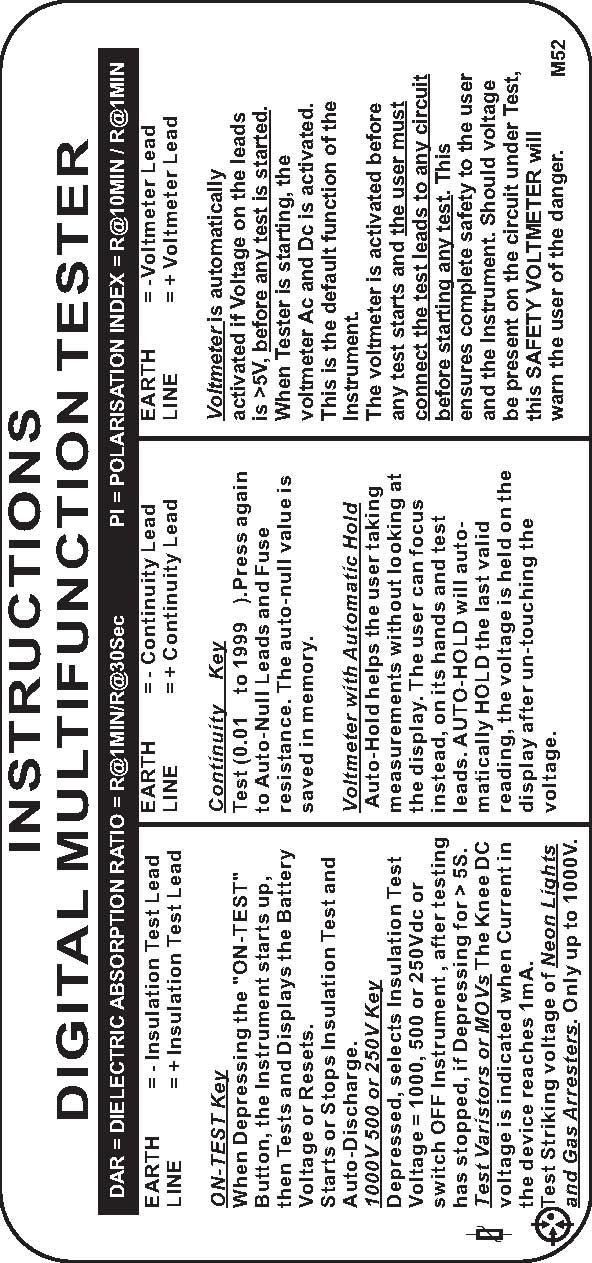
7 The Voltage on the MOV while at 1mA is going through it is displayed on the LCD as well as the equivalent Max AC voltage which could be utilized on this device. GAS Arrester Selection keys On the Multifunction Tester. The GAS test can be accessed by depressing the 500V and Ohm keys simultaneously. This selects the GAS Arrester test. Very similarly to the MOV test, but using an other algorithm, much faster. AUTOMATIC DISCHARGE ON INSULATION TESTS All insulation tests have an automatic discharge which can be monitored on the LCD bar-graph while discharging. The discharge will continue until the voltage is safe. ONLY then, you can disconnect the test leads. NON DESTRUCTIVE TESTS All the tests are using a current of maximum 1mA and are non destructive. The only test which use more than that is the continuity test. It's voltage is 5V maximum. The user should make sure that when doing a test, he knows what he is testing and how he is testing it. Making a sketch of every test will lower the risk of bad testing. If you are not sure of the test you are going to proceed with, ask someone which is qualified to give you the correct answers. PRE-TESTING SAFETY Always check the fuse before using the instrument. This is done by shorting the test leads and selecting the Continuity test. Use this, to null the test leads resistance at the same time. Always clip securely the leads onto the circuit under test. DO NOT JUST TOUCH IT as this could make intermittent contact and therefore the safety features may not work all the times because the connections may not be present at all times. Always connect the test leads and make sure they make proper contacts to the circuit under test before pressing the test buttons. These testers are smart, but can only be as smart as your connections. That means that all the safety features will only work if you have proper connections prior, during and post testing, to the circuit under Test. All safety features can only work if the fuse is intact and correct. Follow the interactive messages on the display. These testers rely completely on you, the user, to connect the leads securely onto the circuit under test before starting any tests and before selecting any test. That means that from the time you switch the tester ON, you should connect securely the test leads from the tester's terminals to the circuit under test. When ever possible, use fused test leads for increased safety. Fused test leads are in series with the existing internal fuse, so the voltage will be divided on both fuses, therefore, reducing the voltage on both fuses and therefore in the worst case, making them safer when opening (breaking the circuit). OPERATING INSTRUCTIONS Leads Connections The Test Leads are color coded for easy use. These testers only use 2 leads which are located on both back extremities of the front panel. The user can visually check these connections at any time. FUNCTIONS When depressing the "ON-TEST" Button, the Instrument starts up or Resets. Please Note: If after a test, no key is depressed for ± 5 minutes, the Instrument will switch off automatically.


8 You can turn OFF the Tester without having to wait for Auto-off. To Turn-Off and switch OFF the tester immediately, Depress the 1kV key for 5 Seconds. If a test is still in Progress, pressing 1kV will stop the test. In this case you need to press 1kV for 5 Sec again. The Batteries are tested automatically at start up. The current Drawn from the batteries is about 300mA. While current is drawn, the total battery voltage is measured and displayed. Note that battery voltage is always monitored during use of the instrument. Should the battery become too low, the low battery symbol will be displayed. AC and DC voltages are automatically detected and shown. This is the default function of the Instrument. The Voltmeter is selected by default by the strument. The voltmeter is activated before any test start and the user must connect the test leads to any circuit before starting any test. This ensures complete safety to the user and the Instrument. Should voltage be present on the circuit under Test, this SAFETY VOLTMETER will warn the user of the danger. As ADDED SAFETY, this Auto-Hold helps the user taking measurement without watching the display. The user can focus instead, on it's hands and test leads. AUTO-HOLD is always enabled, the tester will automatically HOLD the last valid reading, which mean that when the user touch a voltage, that voltage is held on the display even after un-touching the voltage. This add great safety for the user as he can focus on it's safety by only looking at the test leads. EnerSave TM Insulation test Voltage selection is done by Depressing the corresponding key. PI= Polarisation Index DAR = Dielectric Absoprtion Low Ω 200mA SC EnerSave TM is a Smart Program which Save Energy when ever possible by limiting the Test Duration. PI: this is the ratio of the Insulation Resistance at 10 Min divided per the Insulation Resistance at 1 Minute. DAR: this is the ratio of the Insulation Resistance at 1 Min divided per the Insulation Resistance at 30 seconds. Select the Continuity test which has a Short Circuit Current of 200mA. It Complies to all latest standard. Auto-Null the resistance of the test leads and of the fuse so that continuity measurements can show only the resistance under test. Buzzer is always On. Low resistance value BEEP when low. It's helping when tracing circuitry. Pressing the 1000V and 500V keys simultaneously will select the MOV Test. Today's new Equipments and Electrical Installations are generally Protected by MOVs. It is now easy to test these devices to ensure their proper working and replace them if found damaged. The knee Voltage is shown on the display. Pressing the 250V and W keys simultaneously will select the GAS Arrester test Function. The Trigger Threshold Voltage is shown on the LCD. All GAS protection can be tested, including Neon Lights. INSIDE LID INSTRUCTIONS
9
10 VERY IMPORTANT AUTOMATIC FEATURES Automatic Vac-dc Detect. All of these testers in this family have the capability to detect Voltage AC and DC. This is done with the use of the internal safety voltmeter which does this work. However, this feature will only work if the test leads are securely connected to the circuit under test. So, you must ensure that the lest leads are doing a perfect contact before beginning any test and before selecting any function. That contact must remain secure during the entirety of the tests on a particular circuit. We recommend you to use clip-on alligators and not the tips only, so that you can make sure the test leads are making a proper contact during the all duration of the tests. Should the test leads not make contact at any time before, during and after the test, all the safety features of these testers will not functions. It's your responsibility to ensure proper contact of the leads at all times. Automatic Discharge of Capacitive and inductive Circuits These testers will discharge automatically all circuits charged by the tester, after a test is done, again, this will only be activated if the test leads make contact at any time before, during and after the test. It's your responsibility to ensure proper contact of the leads at all times. Once a test is finished, the testers will automatically discharge capacitive or inductive circuit of their charge. The discharge can be observed on the display, in the form of a bar-graph. Again, do not disconnect the leads while discharge. Wait until completion of the discharge before removing any lead. During Discharge, the Buzzer will beep and the bar-graph will show some voltage. With some high charges, this may takes some time. Be patient and let the instrument discharge completely before proceeding to removing the leads. Auto-off This family of instruments has an Auto-off feature which will switch off the tester, should no key or function be in use. Please, again, note that if voltage is present on the leads, the instrument will warn the user of that and the auto-off feature will be inactive until dangerous voltage has been removed from the circuit.
11 FEATURES COMPARISON Insulation Tester Multifunction Tester Digital EE Calibration (No Potentiometers) Keypad Operation Automatic Voltmeter AC/DC at Start / Reset ON-Reset/Restart Key Off Push Button (press more than 5 Sec on 1kV key) Auto-Off MOV / Protection Devices Test Test ON-OFF Polarization Index (PI) on 250, 500 and 1000V Dielectric Absorption Ratio (DAR) on 250, 500 and 1000V Battery Test by Key Test Battery at Start Test Battery at Start Battery Test at Switch ON / Reset Voltmeter on request by Keypad Automatic Automatic Safety Voltmeter before each Test Auto-Discharge on all Test and all Ranges Continuity Short Circuit Current >220mA ( 225mA Typical ) Continuity Open Circuit Voltage of 5V dc Nominal 1mA on all Insulation Ranges Buzzer ON/OFF by Key Always ON Always ON Leads Auto-Null key Test Auto-Stop Display Customization for OEM Re-programmable Microprocessor for Easy Updates Can be calibrated in ALL calibration laboratories Insulation measurement from 2k (250V range) to 8G (1kV Range) Continuity from 0.01 (220mA) to 1999 DC Voltmeter from ±1Vdc to ±950Vdc AC Voltmeter from ±1Vac to ±700Vac Accept 8 Rechargeable Batteries or Alkaline or Normal Smart Hold & Stop on Voltmeter ac / dc GAS Arrester Function EnerSaveTM PRINCIPLE OF HOW THEY WORK-DISPLAYS-RESULTS This family if Test instruments operate through a keypad interface. The number of keys and their function are different on each model. All interactions between the user and the instrument is done via the keypad. The testers have a liquid Crystal Display and two or three terminals. Each push button or key has a function. DIGITAL DISPLAY The digital Liquid Crystal Display is large. It measures (W)98mm x (H)24mm and has a 2Lines of 16 Characters. Language can be changed on demand. Dutch / French / German etc... (Factory fitted at order) FUSED The tester is fused by a fast blow 500mA fuse.
12 CROWBAR PROTECTION In case of misuse, a crowbar is integrated and will blow the fuse. This crowbar will reduce the damages in case of user mistake. The crowbar is activated at less than 6V (ac or dc). AUTOMATIC BATTERY TEST When the tester starts, it test it's batteries by drawing a heavy current from the batteries. During that heavy current, it measures the battery voltage and displays it for a few seconds on the display. During normal use, the tester monitors the battery voltage, but without drawing a battery test current. It just measures the battery while in normal use. SAFETY VOLTMETER Once the battery test is terminated, the tester goes automatically into the Voltmeter mode. It has an Automatic voltmeter AC and DC. The safety voltmeter even has a Hold function built-in. The Hold Function will automatically put the last valid reading on hold if the user disconnects the leads. This is a safety feature, where the user does not need to observe the display but instead observe where he has his hands and probes. This way, safety is increased. The Safety Voltmeter works up to Vdc 900V (both polarities) with resolution of 1V and 1% accuracy. It also measure up to Vac 700V, with the same resolutions and accuracies. INSULATION It has three insulation test Voltages. 250, 500 and 1000V, all of theses are capable of giving more than 1mA at their nominal voltages. 250V Key to select 250Vdc insulation test voltage. 500V Key to select 500Vdc insulation test voltage. 1000V key to select 1000Vdc insulation test voltage. 250V range can measure from 2 K ohms up to 2G ohms 500V range can measure from 4 K ohms up to 4G ohms 1000V range can measure from 8 K ohms up to 8G ohms On some models it automatically calculates the PI and DAR and has an automatic timer. CONTINUITY The continuity test has an open circuit voltage of exactly +5Vdc regulated. The Short Circuit Current of the continuity circuit is about 220mA. The Continuity test can measure from 10 milli- ohm (0.01) up to 2Kohms. The accuracy is better than 1% of reading from 1 ohms to 200 ohms, plus minus one digit. Below 1 ohms, it's better than 5% of readings plus minus 3digits. Above 200 ohms, up to 1999 ohms, it's better than 3% of readings plus minus 3 digits. The Continuity has an auto-nulling facility which is saved into non volatile memories, so you only need to null the leads of fuse again if they are changed. AUTO-OFF They have an auto-off feature and the power automatically turn off after 5 minutes of inactivity. EnerSave The battery life can be saved when the user make spot check. To make a spot check, the user only press the test button for less than 3 seconds, or use the Quick Test key. If the user press the test key for more than 3 seconds, the tester make a long test (timer enabled up to 10 minutes for PI test ). Any test can be stopped at any time. SAFE VOLTMETER DETECTION On any of the tests, if the user connects the leads to a voltage, prior to starting the test, te tester will detect the voltage and automatically turn the Voltmeter ON as well as an alarm. All other test facilities are disabled when this happen. DIGITAL CALIBRATION
13 This family of testers is digitally calibrated. That means that there have no potentiometers or moving part in this product. All the correction factors are saved into the internal memory. BATTERIES The testers can work with 8 x 1.5V batteries. The user can also use rechargeable batteries in the same product. PREPARATION FOR USE Fuses: In doubt, check the fuses using a ohm meter. Please note that this instrument will not indicate anything, should the fuses be blown. Please note that this instrument will be unsafe if the fuse is blown as no indication will be shown and nothing will be detected by it. For that reason, you must verify the fuse before and after any test. Test Leads: Check the test leads for defects or cracks. Replace if cracked or damaged. Only replace with the same type. Use the Continuity test to check, with the fuse(s), that the complete circuit is in good condition. Cleaning: Use a damp cloth to clean the case. Do not use chemicals REPLACE BATTERIES This instrument operates well with Alkaline 1.5V or rechargeable 1.2V batteries. It could be operated with inferior batteries too. It uses 8 of them. To replace the batteries, disconnect the test leads, then unscrew the bottom battery cover and replace the batteries. DISPOSING OF BATTERIES Only dispose of batteries into a purposely dedicated disposal system. Do not dispose to the wrong place. Look after your environment, please. FUSES REPLACEMENT Unscrew the back cover and replace the faulty fuse with the same type, then screw the cover back into place correctly SPECIFICATIONS GENERAL Load Battery Test Current... Battery Voltage Display Accuracy... About 300mA ±0.5V BATTERIES Type alkaline V Other Type V Quantity... 8 DISPLAY Type... 2 lines x 16 Characters AUTO-OFF Automatic Turn OFF Time after last action... LCD 5Min. VOLTMETER (3 minutes maximum) Automatic Voltage DC Range... 0 to 950Vdc Automatic Voltage AC Range... 0 to 700Vac Resolution on both voltage types... ±1V
14 Accuracy on both voltage types... ±1.5% of FS INSULATION TEST Resistance Range 250V Test Voltage... 2k-2G Ohms 500V Test Voltage... 4k-4G Ohms 1000V Test Voltage... 8k-8G Ohms Accuracy... >1MΩ: ±3%rdg 30KΩ-1MΩ: ±5%rdg<30KΩ: ±20%rdg Typical Output 1mA 250V Setting V Max. 500V Setting V Max. 1000V Settings V Max. When Voltage is constant, Current is software Limited at... ±1.2mA Short Circuit Current on all ranges. Maximum Short Circuit Current... ±4mA. Polarization Index Ratio Resolution... ±0.1 Ratio Accuracy... ±1% of Rdg Dielectric Absorption Ratio Ratio Resolution... ±0.1 Ratio Accuracy... ±1% of Rdg Fast Test Test Duration with EnerSave Enabled... 10Sec Long Test Test Duration without EnerSave Enabled... 60Sec. With PI and DAR test function... 10Min. CONTINUITY TEST Short Circuit Current Test... >220mA Open Circuit Voltage... 5Vdc Continuity Range ( Ohms) Continuity Accuracy 0.01 to 100 Ohms... ±1% of Rdg Continuity Accuracy 100 to 300 Ohms... ±1.5% of Rdg Continuity Accuracy 300 to 1999 Ohms... ±2% of Rdg Continuity Resolution... ±2% Counts AUTO-NULL Auto-Null Value Saved in no volatile Memory Auto-Null Threshold... BUZZER Buzzer Threshold... 5 Ohms 3 Ohms MOV TEST Test Voltage Vdc Voltage Results Accuracy... ±3% Voltage Result Resolution... ±2 Counts Measure the Threshold Voltage Calculate the approximate Vac Marking on the MOV (depend on manufacturer) Contact toptronic@telkomsa.net for more details on this function. GAS ARRESTER TEST Test Voltage Vdc Voltage Results Accuracy... ±3% Voltage Result Resolution... ±2 Counts Measure the Threshold Voltage. Contact toptronic@telkomsa.net for more details on this function.
15 PROTECTIONS Over Load... Over Voltage... Fuses... MECHANICAL Size... Material... Weight... Display V (between all terminals) Class III - 700V towards ground. 1 x 500mA/250V, 5 x 20mm 175(L) x 85(W) x 75(H)mm Polycarbonate /A BS Approx 655g(battery included) Liquid Crystal Display ENVIRONMENTAL Operating temperature Range: 1 C to + 55 C not in full sun!!!! Storage Temperature: -20 C to + 70 C CLEANING Clean the instrument case with an anti-static cleaner and wipe with dry cloth. OPTIONS 1. Rechargeable batteries. 2. Pouch. 3. Fused test Leads 4. Calibration Certificate. 5. Fuses. LIMITED WARRANTY We warrant the product manufactured by us to be free from defective material or factory workmanship and agree to repair or replace this product which, under normal use and service, disclose the defect to Bethe fault of our manufacturing, with no charge for parts and service. If we are unable to repair or replace this product, we will make a full refund of the purchase price. Consult the user's manual for proper instruction regarding use of this instrument. Our obligation under this warranty is limited to repairing, replacing or making refund of this test equipment which proves to be defective within twenty four months from the date of original purchase. This warranty does not apply to any of our products which have been repaired or altered by unauthorized persons in any way so as, in our sole judgment, to injure their stability or reliability, or which have been subject to misuse, abuse, misapplication, negligence or accident or which have had the serial numbers altered, defaced or removed. Accessories, not of our manufacture used with this product, are not covered by this warranty. All warranties implied by law are hereby limited to a period of twenty four months, and the provisions of the warranty are expressly in lieu of any other warranties expressed or implied. The purchaser agrees to assume all liability for any damages or bodily injury which may result from the use or misuse of the product by the purchaser, or it's user, his employees, or others, and the remedies provided for in this warranty are expressly in lieu of any other liability we may have including incidental or consequential damages. In this direction will find a vision of the measurement technique: NOTE: "This instrument doesn t have ATEX protection, so it should not be used in potentially explosive atmospheres (powder, flammable gases)."
I I e k ill L ill. INDUSTRIAL DIGITAL EARTH LEAKAGE CIRCUIT BREAKER and 3 PHASE ROTATION TESTER BESANTEK BST-ELC01 INSTRUCTION MANUAL
 = = = = - - - BESANTEK - - BST-ELC1 INDUSTRIAL DIGITAL EARTH LEAKAGE CIRCUIT BREAKER and 3 PHASE ROTATION TESTER EARTH DIGITAL INDUST RIAL ELCB HAS OT ATl ONTE O C, 1:. : ==== === ;... P E R STE R ==!
Digital Low Resistance Ohm Meter
 BST-MGR01 Digital Low Resistance Ohm Meter INSTRUCTION MANUAL Index 1. Safety Rules... 2. Safety Check... 3. General Description... 4. Operating Instructions... 5. Display... 6. Specifications... 11-12
MARTINDALE MARTINDALE IN2001/IN2003 INSULATION & CONTINUITY TESTERS INSTRUCTION MANUAL IN2001/IN2003 INSULATION & CONTINUITY TESTERS
 MARTINDALE ELECTRIC Martindale Electric Company LTD Metrohm House Penfold Trading Estate Imperial Way Watford Herts WD24 4YY T: 01923 441717 F: 01923 446900 Email: sales@martindale-electric.co.uk web:
IN1001/IN1003 ANALOGUE INSULATION & CONTINUITY TESTERS INSTRUCTION MANUAL IN1001/IN1003 ANALOGUE INSULATION & CONTINUITY TESTERS INSTRUCTION MANUAL
 Martindale Electric Company LTD Metrohm House Penfold Trading Estate Imperial Way Watford Herts WD24 4YY T: 01923 441717 F: 01923 446900 Email: sales@martindale-electric.co.uk web: www.martindale-electric.co.uk
USER MANUAL. 10KV Digital High Voltage Insulation Tester. Model MG500. Additional User Manual Translations available at
 USER MANUAL 10KV Digital High Voltage Insulation Tester Model MG500 Additional User Manual Translations available at www.extech.com Introduction Thank you for selecting the Extech Instruments Model MG500.
3 PHASE TESTER & MOTOR ROTATION TESTER
 3 PHASE TESTER & MOTOR ROTATION TESTER R S T TEST CAT. III 500V 3 PHASE TESTER & MOTOR ROTATION TESTER CCW CW BAT. L2 L1 L3 L1 L2 L3 MOTOR ROTATION INSTRUCTION MANUAL INDEX Page 1. INTRODUCTION... 1 2.
Metrohm E3640 FLASH TESTER INSTRUCTION MANUAL. Martindale Electric Co Ltd.
 Metrohm Martindale Electric Metrohm House, Imperial Park, Imperial Way, Watford, Hertfordshire, WD24 4PP, UK T: 01923 441717 F: 01923 446900 Email: sales@martindale-electric.co.uk web: www.martindale-electric.co.uk
Instruction Manual. Model 307A Analog Insulation & Continuity Meter
 Instruction Manual Model 307A Analog Insulation & Continuity Meter Index Page Safety Precautions... 1 Safety Notes... 2 Features... 2-3 Connections... 3 Specifications...... 4 Why Test is necessary...
Chek-A-Cell TM. Instruction Manual Rev A 8/12
 Chek-A-Cell TM Instruction Manual 84-867 Rev A 8/12 INTRODUCTION: The CHEK-A-CELL is a digital battery load tester for all types of batteries in the 5.75 Volt to 20 Volt, 1 to 20 Amp Hour range. Rechargeable
ANALOGUE INSULATION-CONTINUITY and VOLTAGE METER
 99 Washington Street Melrose, MA 02176 Phone 781-665-1400 Toll Free 1-800-517-8431 Visit us at www.testequipmentdepot.com BST-IT26 ANALOGUE INSULATION-CONTINUITY and VOLTAGE METER INSTRUCTION MANUAL Index
BATTERY OPERATED DIGITAL MILLI-OHMMETER
 BATTERY OPERATED DIGITAL MILLI-OHMMETER C 1 P 1 P 2 C 2 MAX. DC20V MICROPROCESSOR CONTROLLED AC DC HOLD M A X M I N AUTO-HOLD Hz mv km ka ms DIGITAL MILLIOHM METER 2000 200.0 20.00 2000m Test Current Range
1KV DIGITAL MULTIFUNCTION INSULATION RESISTANCE AND CONTINUITY-VOLTAGE TESTER WITH MOV & GAS ARRESTER TESTING. Model 1154TMF
 An ISO 9001:2008 Company 1KV DIGITAL MULTIFUNCTION INSULATION RESISTANCE AND CONTINUITY-VOLTAGE TESTER WITH MOV & GAS ARRESTER TESTING FEATURES : Auto Discharge Function on all tests & all ranges. Gas
OPERATING INSTRUCTION
 99 Washington Street Melrose, MA 02176 Phone 781-665-1400 Toll Free 1-800-517-8431 Visit us at www.testequipmentdepot.com 8/05 Form #270 OPERATING INSTRUCTION MODEL 3005 DIGITAL INSULATION-CONTINUITY TESTER
Instruction Manual. Model 310 Digital Milli-Ohm Meter
 Instruction Manual Model 310 Digital Milli-Ohm Meter DESCRIPTION PAGE SAFETY RULES... 01 GENERAL DESCRIPTION... 02-03 FRONT PANEL LAYOUT... 04 PREPARATION FOR USE... 05 PRELIMINARY CHECKS... 05 PRECAUTIONS...
NEW 15KV HIGH VOLTAGE INSULATION RESISTANCE TESTER MODEL KM 7015 IN FEATURES : CAT IV 600V. Short Circuit Current 5mA.
 An ISO 9001:2008 Company 15KV HIGH VOLTAGE INSULATION RESISTANCE TESTER FEATURES : MODEL KM 7015 IN Microprocessor controlled Menu driven. Variable High Voltage : 500 V ~ 15 kv DC. Measuring 30 Insulation
INSPECTOR LINE LOAD SIMULATOR INSTRUCTION MANUAL TASCO, INC.
 INSPECTOR LINE LOAD SIMULATOR INSTRUCTION MANUAL INS120P TASCO, INC. THIS TESTER IS DESIGNED FOR USE ONLY BY QUALIFIED ELECTRICIANS. IMPORTANT SAFETY WARNINGS mwarning Read and understand this material
KMP Insulation-Continuity Tester. Users Manual
 KMP 7036 Insulation-Continuity Tester Users Manual KMP7036 Insulation-Continuity Tester Users Manual English September 2011, Rev.1 2011 Amprobe Test Tools. All rights reserved. Printed in China Limited
KEWTECH. KT56 digital multi function tester. Instruction manual
 KEWTECH KT56 digital multi function tester Instruction manual Contents 1 Safety Notice 1 2 Features and Principles of Measurement 3 3 Introduction 6 4 Specifications 7 5 Instrument layout 9 6 Operating
The function of this Dynamic Active Probe has divided into three preferences on the screen main Menus:
 1.0 Introduction: This probe is designed to provide an additional help to automotive technicians in trouble shooting of electrical circuits problems in the car. Apart from using the normal multi tester,
1 This instrument must only be used by a competent and trained person and operated in strict accordance with the instructions.
 1 This instrument must only be used by a competent and trained person and operated in strict accordance with the instructions. KYORITSU will not accept liability for any damage or injury caused by misuse
OPERATING INSTRUCTION
 11/05 Form #271 99 Washington Street Melrose, MA 02176 Phone 781-665-1400 Toll Free 1-800-517-8431 OPERATING INSTRUCTION Visit us at www.testequipmentdepot.com MODEL 3132 ANALOG INSULATION-CONTINUITY TESTER
MAX. AC 600V HOLD V M H.V. LIVE CIRCUIT DIGITAL INSULATION TESTER DO NOT OPERATE IF LIT POWER DATA HOLD TEST ON / OFF 250V 500V 1000V OFF CAT.
 INSULATION TESTER EARTH MAX. AC 600V LINE AC -+ HOLD V k M LIVE CIRCUIT DIGITAL INSULATION TESTER DO NOT OPERATE IF LIT M H.V. POWER DATA HOLD TEST ON / OFF 250V 500V 1000V ACV OFF 0 CAT.III 600V INSTRUCTION
Atlas ESR. User Guide. Capacitance and Equivalent Series Resistance Meter. Model ESR60 (Enhanced)
") Atlas ESR Capacitance and Equivalent Series Resistance Meter Model ESR60 (Enhanced) User Guide Peak Electronic Design Limited 2004/2008 In the interests of development, information in this guide is subject
Atlas ESR Capacitance and Equivalent Series Resistance Meter Model ESR60 (Enhanced) User Guide Peak Electronic Design Limited 2004/2008 In the interests of development, information in this guide is subject
Instruction Manual. 99 Washington Street Melrose, MA Fax TestEquipmentDepot.com. Model 308A Digital Insulation & Continuity Meter
 Instruction Manual 99 Washington Street Melrose, MA 02176 Fax 781-665-0780 TestEquipmentDepot.com Model 308A Digital Insulation & Continuity Meter INDEX PAGE INSTRUMENT LAYOUT... 1 INTRODUCTION... 2 SAFETY
User Guide. Model Insulation Tester / Megohmmeter. Introduction
 User Guide Model 380363 Insulation Tester / Megohmmeter Introduction Congratulations on your purchase of Extech s Insulation Tester/Megohmmeter. The Model 380363 provides three test ranges plus continuity
Atlas ESR and ESR + Equivalent Series Resistance and Capacitance Meter. Model ESR60/ESR70. Designed and manufactured with pride in the UK.
 GB60/70-9 Atlas ESR and ESR + Equivalent Series Resistance and Capacitance Meter Model ESR60/ESR70 Designed and manufactured with pride in the UK User Guide Peak Electronic Design Limited 2004/2016 In
HIGH VOLTAGE PROVING UNIT
 HIGH VOLTAGE PROVING UNIT INSTRUCTION MANUAL Index 1. Safety Precautions... 2. Specifications... 3. Features... 4. Connections... 5. Layout of Tester... 6. Instructions Label... 7. Proofing Methods...
1.Safe testing IMPORTANT:
 Electricity is dangerous and can cause injury and death. Always treat it with the greatest of respect and care. If you are not quite sure how to proceed, then stop, take advice from a qualified person.
USER MANUAL. Insulation Tester + DMM. Model MG320
 USER MANUAL Insulation Tester + DMM Model MG320 Table of Contents 1. INTRODUCTION 3 2. SAFETY 3 3. METER DESCRIPTION 5 4. CONTROL BUTTONS 6 5. SYMBOLS AND ANNUNCIATORS 6 6. OPERATING INSTRUCTIONS 7 6.1
Digital/Analog Megohmmeter Model 1026 USER MANUAL
 Digital/Analog Megohmmeter Model 1026 USER MANUAL Limited Warranty The Megohmmeter Model 1026, is warranted to the owner for a period of 2 years from the date of original purchase against defects in manufacture.
HIGH VOLTAGE PROXIMITY DETECTOR
 HIGH VOLTAGE PROXIMITY DETECTOR An ISO 9001:2008 Company Model 275 HP (Upto 275KV) / 500 HP (Upto 500KV) The 275HP / 500HP is a HIGH VOLTAGE proximity detector. 275HP has eight voltage detection settings
TRIPLETT. Model 310 Type C Type 9
 TRIPLETT Model 310 Type 9 310-C Type 9 TABLE OF CONTENTS SAFETY RULES... 2 INTRODUCTION...8 SPECIFICATIONS... 9 GENERAL INSTRUCTIONS... 11 Test Leads... 11 Range Selection... 11 Scale Selection... 12
MIT300 Series Insulation and Continuity Testers
 MIT300_UG_en_V11.qxp 14/1/09 3:03 pm Page 1 M MIT300 Series Insulation and Continuity Testers Megger MIT300-EN MIT 300 EN Insulation Resistance Continuity Tester Megger MIT310A-EN MIT 310A EN Insulation
INSTRUCTION MANUAL PORTABLE APPLIANCE TESTER
 INSTRUCTION MANUAL PORTABLE APPLIANCE TESTER KEW6201A CONTENTS 1. Safe testing 1 2. Procedure of removing cover. 3 2.1 Method of removing the cover. 3 2.2 Method of storing the cover. 3 3. Product summary
Model Battery Powered Milliohm Meter
 User s Guide Model 380580 Battery Powered Milliohm Meter Introduction Congratulations on your purchase of Extech s Model 380580 Battery Powered Milliohm Meter. This device offers five resistance ranges
MY /2-DIGIT DIGITAL MULTIMETER Users Manual
 MY-65 4 1/2-DIGIT DIGITAL MULTIMETER Users Manual Read the Users Manual thoroughly before use. WARRANTY This instrument is warranted to be free from defects in material and workmanship for a period of
User's Manual Digital High Voltage Insulation Tester Model
 99 Washington Street Melrose, MA 02176 Phone 781-665-1400 Toll Free 1-800-517-8431 Visit us at www.testequipmentdepot.com Back to the Extech 380375 Product Page User's Manual Digital High Voltage Insulation
Digital/Analog Megohmmeter Model 1026
 Digital/Analog Megohmmeter Model 1026 USER MANUAL 99 Washington Street Melrose, MA 02176 Phone 781-665-1400 Toll Free 1-800-517-8431 Visit us at www.testequipmentdepot.com Table of Contents Warning...3
INSTRUCTION MANUAL CM95/ CM100 TRUE RMS FLEXIBLE CLAMP METER. 1. SAFETY INFORMATION: Always read before proceeding. REMEMBER: SAFETY IS NO ACCIDENT
 CM95/ CM100 TRUE RMS FLEXIBLE CLAMP METER INSTRUCTION MANUAL 1. SAFETY INFORMATION: Always read before proceeding. REMEMBER: SAFETY IS NO ACCIDENT These instructions contain both information and warnings
MIT515, MIT525, MIT1025, MIT1525
 MIT515, MIT525, MIT1025, MIT1525 Measures up to 30 TΩ Safety rated up to CAT IV 1000 V to 3000 m Unique dual-case design - additional user protection Operates from battery or a.c. mains supply Rapid charge
MANUAL ELECTROMAGNETIC FIELD RADIATION TESTER EMF 823
 www.pce-industrial-needs.com Tursdale Technical Services Ltd Unit N12B Tursdale Business Park Co. Durham DH6 5PG United Kingdom Phone: +44 ( 0 ) 191 377 3398 Fax: +44 ( 0 ) 191 377 3357 info@tursdaletechnicalservices.co.uk
S1-568, S1-1068, S1-1568
 S1-568, S1-1068, S1-1568 Resistance range up to 35 TΩ 8 ma noise rejection plus 4 filters Safety up to CATIV 1000V to 4000 m Rapid charge Li-ion battery meets IEC62133 Operate with flat battery from an
UP100AC INSTRUCTION MANUAL
 UP100AC AC/DC Charger INSTRUCTION MANUAL 100W 10A TABLE OF CONTENTS Introduction... 2 Special Features... 4 Warning and Safety Notes... 6 Lithium Battery Connection Diagram... 10 Operation Diagram - Homepage...
BM kv Digital Insulation Tester USER MANUAL
 M BM5200 5 kv Digital Insulation Tester USER MANUAL CONTENTS Safety warnings...3 Symbols used on instrument...4 Cleaning...4 General description...5 Insulation resistance test modes...5 Automatic discharge...5
DIGITAL INSULATION RESISTANCE TESTER (5KV, 1T )
") An ISO 9001:2008 Company DIGITAL INSULATION RESISTANCE TESTER (5KV, 1T ) Model - KM 2805 MK-1 insulation resistance tester is a handheld instrument designed primarily to make resistance / insulation resistance
An ISO 9001:2008 Company DIGITAL INSULATION RESISTANCE TESTER (5KV, 1T ) Model - KM 2805 MK-1 insulation resistance tester is a handheld instrument designed primarily to make resistance / insulation resistance
INSTRUCTION MANUAL ANALOGUE INSULATION TESTER KEW 3131M KYORITSU ELECTRICAL INSTRUMENTS WORKS,LTD., TOKYO JAPAN
 INSTRUCTION MANUAL ANALOGUE INSULATION TESTER KEW 3131M KYORITSU ELECTRICAL INSTRUMENTS WORKS,LTD., TOKYO JAPAN Contents 1. Safety Precautions... 1 2. Features... 3 3. Specifications... 4 4. Instrument
This instrument is manufactured in the United Kingdom. The company reserves the right to change the specification or design without prior notice.
 M Megger Limited Archcliffe Road, Dover Kent CT17 9EN England T +44 (0)1 304 502101 F +44 (0)1 304 207342 E uksales@megger.com Megger Z.A. Du Buisson de la Couldre 23 rue Eugène Henaff 78190 TRAPPES France
SAFETY PRECAUTIONS AND WARNINGS...
 Table of Contents 1. SAFETY PRECAUTIONS AND WARNINGS... 1 2. USING THE TEST TOOL... 2 2.1 TOOL DESCRIPTION... 2 2.2 SPECIFICATIONS... 3 2.3 ACCESSORIES INCLUDED... 3 2.4 GENERAL DESCRIPTION... 4 2.5 POWER...
User's Manual. Earth Ground Resistance Tester. Model Introduction
 User's Manual Earth Ground Resistance Tester Model 382152 Introduction Congratulations on your purchase of the Extech Earth Ground Resistance Tester. This device can measure resistance (in 3 ranges) and
Dawson DDM190D. Digital Multimeter User s Manual
 Dawson DDM190D Digital Multimeter User s Manual TABLE OF CONTENTS LIMITED WARRANTY AND LIMITATION OF LIABILITY... 3 Out of the Box... 3 Accessories... 4 Safety Information... 7 Certification... 7 INTRODUCTION...
DT33B/C/D OPERATOR S MANUAL LIMITED WARRANTY AND LIMITATION OF LIABILITY
 BACK LIGHT D I G I TA L M U LT I M E T E R DT33B OPERATOR LIMITED WARRANTY AND LIMITATION OF LIABILITY This product will be free from defects in material and workmanship for one year from the date of purchase.
User's Manual. High Voltage Megohmmeter. Analog Insulation Tester plus AC Voltage and Continuity Tests. Model
 User's Manual High Voltage Megohmmeter Analog Insulation Tester plus AC Voltage and Continuity Tests Model 380353 Warranty EXTECH INSTRUMENTS CORPORATION warrants this instrument to be free of defects
KTD30 Digital Insulation and Continuity Tester. User Manual. kewtechcorp.com
 KTD30 Digital Insulation and Continuity Tester User Manual 1 kewtechcorp.com The Kewtech KTD30 Continuity Insulation Tester is designed for use by suitably qualified personnel familiar with electrical
IDEAL INDUSTRIES INC. TECHNICAL MANUAL - SUPPLEMENT MODEL
 IDEAL INDUSTRIES INC. TECHNICAL MANUAL - SUPPLEMENT MODEL 61-791 The Service Information provides the following: This is a Supplemental Manual to Megger s DM220 Service Manual and is intended for Performance
HT Dielectric Withstand Tester Volts AC Output 25mA Leakage Option
 HT-10000 Dielectric Withstand Tester 0-10000 Volts AC Output 25mA Leakage Option Instruction Manual COMPLIANCE WESTUSA Dear Customer: Congratulations! Compliance West USA is proud to present you with your
TMD90A Dual Input Digital Thermometer
 TMD90A Dual Input Digital Thermometer User Manual For detailed specifications and ordering info go to www.testequipmentdepot.com TMD90A Dual Input Thermometer Contents Safety Information 2 Symbols Used
INTRODUCTION. Specifications. Operating voltage range:
 INTRODUCTION INTRODUCTION Thank you for purchasing the EcoPower Electron 65 AC Charger. This product is a fast charger with a high performance microprocessor and specialized operating software. Please
Instruction Manual PC104/PC105 3-PHASE SOCKET TESTER. Check out what else you can get from Martindale:
 Check out what else you can get from Martindale: 17th Edition Testers Accessories Calibration Equipment Continuity Testers Electricians Kits Environmental Products Full Calibration & Repair Service Fuse
LH41A. User Manual. Clamp On Ammeter. For detailed specifications and ordering info go to
 LH41A Clamp On Ammeter User Manual For detailed specifications and ordering info go to www.testequipmentdepot.com LH41A Clamp On Ammeter Users Manual English April 2007, Rev.2 2007 Amprobe Test Tools.
Table of Contents Title Page No.
 Table of Contents Title Page No. INTRODUCTION 1 SAFETY PRECAUTIONS / WARNINGS 2 CONTROLS AND INDICATORS 4 PREPARATION AND CAUTION BEFORE USE 5 TESTING PROCEDURES 6 A. AC/DC VOLTAGE MEASUREMENT 6 B. RESISTANCE
TIC 300 PRO. Users Manual Mode d emploi Bedienungshandbuch Manual d uso Manual de uso. Non Contact AC Voltage Detector. High Energy Tic Tracer
 TIC 300 PRO High Energy Tic Tracer Non Contact AC Voltage Detector Users Manual Mode d emploi Bedienungshandbuch Manual d uso Manual de uso TIC 300 PRO High Energy Tic Tracer Non Contact AC Voltage Detector
OPERATING INSTRUCTIONS
 CM OPERATING INSTRUCTIONS 9 Function, Auto Range Digital Multi-Meter DM6450 INTERTEK Read this owner s manual thoroughly before use and save. C LISTED US I. DISPLAY FUNCTIONS & SYMBOLS 9 6 10 11 14 8 7
MARTINDALE INSTRUCTIONS ELITE FUSE FINDER KIT ELECTRIC. Trusted by professionals. 4.4 Storage Conditions
 4.4 Storage Conditions The FD650/R and FD500/T or FD600/T should be kept in warm dry conditions away from direct sources of heat or sunlight, with the battery removed and in such a manner as to preserve
Tension your belts at the speed of light!
 Tension your belts at the speed of light! OVERVIEW The Carlisle Frequency-Finder (part number 109061) is an electronic measuring instrument that precisely measures the static tension in Synchronous, V-Belts,
60 Watt Industrial LED Low Bay Light
 60 Watt Industrial LED Low Bay Light Owner s Manual WARNING: Read carefully and understand all ASSEMBLY AND OPERATION INSTRUCTIONS before operating. Failure to follow the safety rules and other basic safety
Switching DC Power Supply
 99 Washington Street Melrose, MA 02176 Phone 781-665-1400 Toll Free 1-800-517-8431 Visit us at www.testequipmentdepot.com Model 1693, 1694 Switching DC Power Supply INSTRUCTION MANUAL 1 Safety Summary
Elite Power Solutions Automatic Battery Control (ABC) Operation Manual
 Operation Manual") Elite Power Solutions Automatic Battery Control (ABC) Operation Manual Elite Power Solutions 335 E Warner Rd. STE 3 Chandler, AZ 85225 www.elitepowersolutions.com ABC Operation Manual Page 1 Table of Contents
Elite Power Solutions Automatic Battery Control (ABC) Operation Manual Elite Power Solutions 335 E Warner Rd. STE 3 Chandler, AZ 85225 www.elitepowersolutions.com ABC Operation Manual Page 1 Table of Contents
DC-AC Power Inverter SAM Manual. Please read this manual before installing your inverter
 DC-AC Power Inverter SAM-100-12 Owner's Manual Please read this manual before installing your inverter WARNINGS TO REDUCE THE RISK OF FIRE, ELECTRIC SHOCK, EXPLOSION OR INJURY 1. Do not connect to AC distribution
DIGITAL RCD(ELCB) TESTER
 TESTER") INSTRUCTION MANUAL DIGITAL RCD(ELCB) TESTER KEW 5410 R KYORITSU ELECTRICAL INSTRUMENTS WORKS, LTD. Contents 1. Safety Warnings.... 1 2. Procedure of removing Cover. 3 2-1 Method of removing the Cover.
INSTRUCTION MANUAL DIGITAL RCD(ELCB) TESTER KEW 5410 R KYORITSU ELECTRICAL INSTRUMENTS WORKS, LTD. Contents 1. Safety Warnings.... 1 2. Procedure of removing Cover. 3 2-1 Method of removing the Cover.
Instruction Manual VT4 VOLTAGE TESTER. Check out what else you can get from Martindale:
 Check out what else you can get from Martindale: 17th Edition Testers Accessories Calibration Equipment Continuity Testers Electricians Kits Environmental Products Full Calibration & Repair Service Fuse
OPERATING INSTRUCTIONS
 OPERATING INSTRUCTIONS Digital Clamp Meter DSA500A IMPORTANT: RECEIVING INSTRUCTIONS Visually inspect all components for shipping damage. If you find damage, notify the carrier at once. Shipping damage
OPERATIONAL MANUAL EMBC-8025 INTELLIGENT BATTERY CHARGER. Version 1.5
 OPERATIONAL MANUAL EMBC-8025 INTELLIGENT BATTERY CHARGER Version 1.5 1 Product Overview EMBC-8025 is an intelligent switching mode battery charger with float maintenance. It is designed to offer maximum
DC to DC Step Up Converter Model: VTC305
 DC to DC Step Up Converter Model: VTC305 Owner's Manual Please read this manual before operating your converter INTRODUCTION Step up a 12 VDC battery to between 13.5 and 17.0 or 24.0 and 27.5 VDC in 0.5
Battery Back-up Model: BBM-1225
 Battery Back-up Model: BBM-1225 Owner's Manual Please read this manual before operating your INDEX Safety instructions... 2 Description... 2 Principle of operation...3,4,5,6 Installation... 7,8 Specifications...
Item ref: UK & UK MTB01 & MTB02 DIGITAL MULTITESTERS. User Manual
 Item ref: 600.101UK & 600.102UK MTB01 & MTB02 DIGITAL MULTITESTERS User Manual Please read this manual thoroughly and ensure all contents are fully understood before using the apparatus. Warning To avoid
INSTRUCTION MANUAL DT173 DT175 DIGITAL THERMOMETERS ALWAYS READ THESE INSTRUCTIONS BEFORE PROCEEDING
 DIGITAL THERMOMETERS INSTRUCTION MANUAL ALWAYS READ THESE INSTRUCTIONS BEFORE PROCEEDING Thank you for buying one of our products. For safety and a full understanding of its benefits please read this manual
Manual Calibrator PCE-IC1
 www.pce-industrial-needs.com Tursdale Technical Services Ltd Unit N12B Tursdale Business Park Co. Durham DH6 5PG United Kingdom Phone: +44 ( 0 ) 191 377 3398 Fax: +44 ( 0 ) 191 377 3357 info@tursdaletechnicalservices.co.uk
T R A N S F O R M I N G T E C H N O L O G I E S, L L C O U T S T A N D I N G A L T E R N A T I V E S I N S T A T I C C O N T R O L
 T R A N S F O R M I N G T E C H N O L O G I E S, L L C O U T S T A N D I N G A L T E R N A T I V E S I N S T A T I C C O N T R O L Ohm Metrics Static Field Meter & Ionizer Verification Unit Model EFM115
Model NTX7 Series Automatic Battery Charger User s Manual Rev. 1.0 October 17, 2006
 B R A N D Model NTX7 Series Automatic Battery Charger User s Manual Rev. 1.0 October 17, 2006 For Sales, Support and Service phone: 407-331-4793 fax: 407-331-4708 website: www.xenotronix.com email: information@xenotronix.com
EZYPAT / EZYPAT+ / SMARTPAT PORTABLE APPLIANCE TESTER INSTRUCTION MANUAL
 EZYPAT / EZYPAT+ / SMARTPAT PORTABLE APPLIANCE TESTER INSTRUCTION MANUAL CONTENTS 1. Safe testing... 2 2. Product summary and explanation... 5 2.1 Product summary... 5 2.2 Test Function... 5 2.3 Features...
INSTRUCTION MANUAL CM69 TRMS AC EARTH LEAKAGE CLAMP METER. 1. SAFETY INFORMATION: Always read before proceeding. REMEMBER: SAFETY IS NO ACCIDENT
 CM69 TRMS AC EARTH LEAKAGE CLAMP METER INSTRUCTION MANUAL 1. SAFETY INFORMATION: Always read before proceeding. REMEMBER: SAFETY IS NO ACCIDENT These instructions contain both information and warnings
OPERATING INSTRUCTION
 11/05 Form #273 OPERATING INSTRUCTION MODEL 4105 Disital Earth Resistance Tester 2150 joshua's Path, Suite 302, Hauppauge, NY 11788 Phone : 1-800-645-5398 or 1-639-231-7050 Fax : 1-639-434-3128 E-mail
POWERED BY KT71 / Portable Appliance Tester. Instruction Manual
 KT71 / Portable Appliance Tester POWERED BY Instruction Manual CONTENTS 1. Safe testing 1 2. Procedure of removing cover.. 3 2.1 Method of removing the cover... 3 2.2 Method of storing the cover... 3 3.
RS-3 PRO RS-1007 PRO. CAT IV Analog Clamp meter Series. Users Manual. For detailed specifications and ordering info go to
 RS-3 PRO RS-1007 PRO CAT IV Analog Clamp meter Series Users Manual For detailed specifications and ordering info go to www.testequipmentdepot.com RS-3 PRO RS-1007 PRO CAT IV Analog Clampmeter Series English
KTD30 Digital Insulation and Continuity Tester
 KTD30 Digital Insulation and Continuity Tester User Manual www.kewtechcorp.com 1 The Kewtech KTD30 Loop Impedence Tester is designed for use by suitably qualified personnel familiar with electrical supply
TRIPLETT. Series. Type 3. Railroad Test Sets Instruction Manual /07
 TRIPLETT 2000 Series Type 3 Railroad Test Sets Instruction Manual Model 2000 Model 2001 Model 2002 Model 2003 84-873 7/07 SAFETY RULES Warning This Tester has been designed with your safety in mind. However,
ASTROAI USER MANUAL DIGITAL MULTIMETER. NOTE: Fully read and understand this manual before using this instrument.
 ASTROAI USER MANUAL DIGITAL MULTIMETER NOTE: Fully read and understand this manual before using this instrument. WARNING: To avoid possible electric shock or personal injury, and to avoid possible damage
BellMega BM-510. Operation Manual Ver: 1.0 Rev: 1
 BellMega BM-510 Operation Manual Ver: 1.0 Rev: 1 CONTENTS Page Description 1 Operation 2 Safety 2 Charging 3 Service / Calibration 3 Specifications 4 Description The BellMega is a continuity tester for
TABLE OF CONTENTS. 8.3 Online Sensor Specifications. Series TS (Models TS1, TSP, TSH, TSL,TSF, TSB1, TSB2) According to Electromatic factory procedure
 According to Electromatic factory procedure") 8.3 Online Sensor Specifications Series TS (Models TS1, TSP, TSH, TSL,TSF, TSB1, TSB2) Calibration: Accuracy: Remainder of range and other calibration material Overload protection Measuring principle Measuring
8.3 Online Sensor Specifications Series TS (Models TS1, TSP, TSH, TSL,TSF, TSB1, TSB2) Calibration: Accuracy: Remainder of range and other calibration material Overload protection Measuring principle Measuring
Safety design conforming to the following provisions
 Safety design conforming to the following provisions of IEC61010. Overvoltage category III 300V AC, pollution degree 2 Overvoltage category II 600V AC/DC, pollution degree 2 Protected throughout by double
7/05 FORM#347 OPERATING INSTRUCTIONS MULTI FUNCTION TESTER MODEL 6030
 7/05 FORM#347 OPERATING INSTRUCTIONS MULTI FUNCTION TESTER MODEL 6030 Contents 1. Safety Precautions 1 2. Features 3 3. Specifications 4 4. Layout Diagram 7 5. Preparation for Measurement 9 6. Operation
INSTALLATION/OPERATING INSTRUCTIONS TSC
 INSTALLATION/OPERATING INSTRUCTIONS TSC Two-Stage Set Point Control with External Activation Two-Stage Heating (Rotation Included) Two-Stage Cooling (Rotation Included) Change-Over Control (Heat/Cool)
Users Manual. MegOhmMeter
 1520 MegOhmMeter Users Manual September 2000 Rev.2, 2/03 2000-2003 Fluke Corporation. All rights reserved. Printed in USA All product names are trademarks of their respective companies. Table of Contents
Model HPX60 Series Automatic Battery Charger User s Manual Rev. 1.0 October 17, 2006
 B R A N D Model HPX60 Series Automatic Battery Charger User s Manual Rev. 1.0 October 17, 2006 For Sales, Support and Service phone: 407-331-4793 fax: 407-331-4708 website: www.xenotronix.com email: information@xenotronix.com
OPERATING INSTRUCTIONS PLEASE READ CAREFULLY
 OPERATING INSTRUCTIONS PLEASE READ CAREFULLY 925-0330 Rev 0 0416 TABLE OF CONTENTS SAFETY SUMMARY... 3 SPECIFICATIONS... 4 1.0 INTRODUCTION/DESCRIPTION.... 5 2.0 LOCATION AND MOUNTING... 5 3.0 CONNECTIONS
AC POWER SOURCE PURE SINE WAVE DC-AC INVERTERS OWNER S MANUAL
 AC POWER SOURCE PURE SINE WAVE DC-AC INVERTERS MODEL: PST-15S-12A OWNER S MANUAL Please read this manual before operating your inverter. INDEX Contents General Safety & Installation... 3 Warning... 4 Description
Calibrator Capabilities Function Range Resolution Measure V dc 28 V 1 mv Measure ma dc Source ma dc
 707 Loop Calibrator Instruction Sheet Introduction The Fluke 707 Loop Calibrator (hereafter, the Calibrator) is a compact sourcing and measuring tool. The Calibrator tests current loops of 0-20 ma or 4-20
Mini Multimeter with Non-Contact Voltage Detector (NCV)
") Owner s Manual Mini Multimeter with Non-Contact Voltage Detector (NCV) Model No. 82314 CAUTION: Read, understand and follow Safety Rules and Operating Instructions in this manual before using this product.
Owner s Manual Mini Multimeter with Non-Contact Voltage Detector (NCV) Model No. 82314 CAUTION: Read, understand and follow Safety Rules and Operating Instructions in this manual before using this product.
PURE SINE WAVE DC-AC INVERTERS
 AC POWER SOURCE PURE SINE WAVE DC-AC INVERTERS MODEL: PST-60S-24A OWNER S MANUAL Please read this manual before operating your inverter. INDEX Contents General Safety & Installation... 3 Warning... 4 Description
99 Washington Street Melrose, MA Fax TestEquipmentDepot.com. Instruction Manual. Model 2831D 4 ½ Digit True RMS Digital Multimeter
 99 Washington Street Melrose, MA 02176 Fax 781-665-0780 TestEquipmentDepot.com Instruction Manual Model 2831D 4 ½ Digit True RMS Digital Multimeter 1 1. PRODUCT DESCRIPTION 1-1. Introduction Thank you