IMPORTANT OWNER-OPERATOR INSTALLATION INSTRUCTIONS. A Hidden Power
|
|
|
- Dylan Hodges
- 5 years ago
- Views:
Transcription

1 IMPORTANT OWNER-OPERATOR INSTALLATION INSTRUCTIONS A Hidden Power
 1 50 AMP Wire Connectors 2 1/2-13 x")

2 Parts Inventory Image Item Description Quantity A7726 Battery Tray 1 A7726 Rear Side Plate 1 A7726 Front Side Plate 1 Group 24 Battery Box (with strap) 1 50 AMP Wire Connectors 2 1/2-13 x 1-1/4 Grade 5 Hex Bolt 4 1/2-13 Grade 5 Hex Nut 4 1/2 Lock Washer 4 1/2 Star Washer 4 1/2 USS Flat Washer 4 3/8-16 Nylock Hex Nut 4 3/8 x 1-1/2 Fender Washer 4 1/4-20 x 1 Hex Bolt 4 1/4 Lock Washer 4
3 1/4 Flat Washer 4 1/4 x 1-1/4 Fender Washer 4 1/4-20 Hex Nut 4 1/4 Clevis pin and clip 2 1/2 Bolt fisher 2

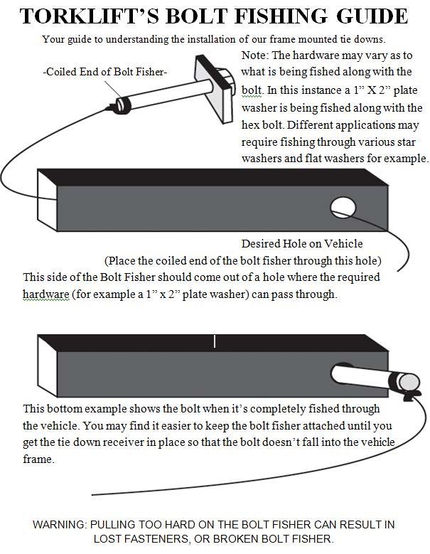
4 Step 1: Locate the area of install directly above the forward most leaf spring hanger on the passenger side of the vehicle. Begin by using the two supplied bolt fishers to fish one 1/2-13 x 1-1/4 Grade 5 Bolt with one 1/2 Star washer through holes 1 and 2 as shown. Reference photo 1.1 and the bolt fishing guide at the end of this instruction booklet. Photo Oval Bolt Fishing Hole 3 4 Leaf Spring Hanger

5 Step 2: With the threads of the two 1/2-13 x 1-1/4 Grade 5 bolts sticking out of the frame, place the Rear Side Plate over the bolts by pulling the bolt fishers through each hole in the Rear Side Plate. The key holes in the plate should be facing the ground. Remove one bolt fisher and install one 1/2 Flat washer, one 1/2 Lock Washer and one 1/2-13 Hex Nut onto the bolt. Leave hand tight at this time. Remove the remaing bolt fisher and install the same hardware onto the second bolt. Reference photo 2.1 for the proper plate orientation and hardware installation. Leave hardware hand tight at this time. Photo 2.1 Rear Side Plate Front Side Plate
6 Step 3: Reuse the two supplied bolt fishers to fish one 1/2-13 x 1-1/4 Grade 5 Bolt with one 1/2 Star washer through holes 3 and 4 in the vehicle frame. Place the Front Side Plate over the bolts by pulling the bolt fishers through each hole in the Front Side Plate. The key holes in the plate should be facing the ground. Remove one bolt fisher and install one 1/2 Flat washer, one 1/2 Lock Washer and one 1/2-13 Hex Nut onto the bolt. Remove the remaing bolt fisher and install the same hardware onto the second bolt. Reference photo 2.1 and leave hardware hand tight. Step 4: Lift the battery tray up into place between the two side plates so that the bolt studs stick through the keyhole slots. Clamp the side plates against the battery tray to properly align all the parts. Alternately, install one 3/8 fender washer and one 3/8 nylock hex nut onto one of the protruding studs on each side of the battery tray. Tighten until the side plates are flush with the battery tray but not clamped tightly in place. Figure 4.1
7 Step 5: With all three parts properly aligned, tighten the four 1/2 hex nuts securing the side plates to the vehicle frame. Remove the battery tray from the keyhole slots once the side plates are secure. This can be done by removing the clamp or loosening the two 3/8 nylock hex nuts used in step four. Torque the four 1/2 hex nuts to 55 ft-lbs. At this point, the installation should look like photo 2.1 on the previous page. Step 6: Place the supplied Battery Box on top of the Battery Tray and slide it all the way to the side that has the four holes in the bottom, leaving approximately 3/8 between the battery box and the bent up flange on the tray. Mark and drill four holes in your Battery Box that line up with the Battery Tray. Install one ¼ -20 x 1 Hex Bolt with one ¼ x 1- ¼ Fender Washer through each of the four holes from the inside of the box outward through the battery tray. Secure them with one ¼ Flat Washer, ¼ Lock washer and ¼ Hex Nut. Tighten each hex nut until the lock washer is pressed flat, and then one additional quarter turn. Refer to figure 6.1 on the next page for the correct Battery Box mounting.
8 Figure 6.1 Step 7: Place your battery inside the Battery Box and connect the battery cables (not included) to the appropriate battery terminals. Two 50amp quick disconnect terminals are included in the kit to make installation and removal of the battery tray easier. Use the supplied strap to secure the lid closed. One 50amp terminal should be hanging outside the box by a short length of wire. This will connect to the vehicle side of the wiring once the battery tray is installed.

9 Step 8: With you Battery Box bolted onto your Battery Tray and the battery installed, lift the assembly up between the side plates and lock the tray into the keyhole slots. Secure the battery tray in place with two 1/4 Pin and clips. Install one 3/8 x 1-1/2 Fender Washer and one 3/8 Nylock Hex Nut onto each of the four protruding studs. Refer to photo 6.1 for the completed installation. Torque all four 3/8 Nylock Hex Nuts to 20 ft-lbs Photo 6.1 At this time, you have completed the installation.

10 Battery Charging Wire Diagrams To test if you have a factory battery separator, use a voltmeter or a 12V test light to test for key on/ key off positive power at the RV Plug. See RV Plug Diagram on next page. NOTE: Wire color is going to vary from manufacturer to manufacturer which is why you should always wire by function and use a Volt Meter or a 12V test light when wiring. There is no official industry standard for wire color. If you are trying to wire by matching colors, there is a very good chance that it will be wired incorrectly. Be sure to test each wire to ensure you are wiring for the correct function.
11
12
13
IMPORTANT OWNER-OPERATOR INSTALLATION INSTRUCTIONS A7728 HIDDEN POWER APPLICATION: FORD F250/F350/F450 with Battery Box
 IMPORTANT OWNER-OPERATOR INSTALLATION INSTRUCTIONS A7728 HIDDEN POWER APPLICATION: 2008-2012 FORD F250/F350/F450 with Battery Box A7728 INVENTORY LIST 1- Frame Plate 1- Side Gusset 1- Bent Hook Bracket
Important: Please read these instructions carefully and completely before starting the installation. TITAN Fuel Tanks INSTALLATION INSTRUCTIONS
 TITAN pt. no.: 03 0000 0141 Important: Please read these instructions carefully and completely before starting the installation. TITAN Fuel Tanks INSTALLATION INSTRUCTIONS Extended Capacity Replacement
INSTALLATION INSTRUCTIONS DRAWERS #240
 INSTALLATION INSTRUCTIONS DRAWERS #240 Please read and fill out the enclosed warranty registration card to activate your warranty. SHIPMENT CONTENTS #1 Lid #2 Rear #3 Left side panel #4 Right side panel
INSTRUCTIONS INSTRUCCIONES CONSIGNES
 AUTOMOTIVE PRODUCTS, INC. INSTRUCTIONS INSTRUCCIONES CONSIGNES APPLICATION: 2013-UP FORD ESCAPE APP PART # 28-21010, 28-21015 STYLIZED RUNNING BOARD ITEM QUANTITY DESCRIPTION TOOLS NEEDED 1 2 RUNNING BOARDS
05+ Toyota Tacoma Rear Shock Hoop Install Notes Part# 86460
 159 North Maple St. Unit J, CORONA CA 92880 P. 951-737-9682 F. 951-737-9006 WWW.CHAOSFAB.COM 05+ Toyota Tacoma Rear Shock Hoop Install Notes Part# 86460 Note: This kit is designed to work with the Total
Extended Capacity Replacement Tanks for RAM Cummins Diesel Trucks
 TITAN pt. no.: 03 0000 0135 Important: Please read these instructions carefully and completely before starting the installation. TITAN Fuel Tanks INSTALLATION INSTRUCTIONS G e n e r a t i o n V Extended
INSTALLATION INSTRUCTION BULL BAR DODGE RAM 1500 PART NUMBER
 INSTALLATION INSTRUCTION 09-12 DODGE RAM 1500 PART NUMBER - 200691 PARTS LIST: Qty Description Qty Description 1 Bull Bar 10 12mm Lock Washers 2 Upper Frame Mounting Brackets (for trucks without tow hooks
STOP---READ THIS FIRST!
 STOP---READ THIS FIRST! **Read These Entire Instructions Before Starting Anything** 2003-2013 DODGE Ram 2500/3500, 8 LIFT KIT NOTE: * The factory wheels and tires WILL fit on the front of the vehicle once
INSTALLATION INSTRUCTIONS C-VS-2000-DUR-1 20 VEHICLE SPECIFIC CONSOLE for 2018 Dodge Durango with Standard Shifter
 INSTALLATION INSTRUCTIONS C-VS-2000-DUR-1 20 VEHICLE SPECIFIC CONSOLE for 2018 Dodge Durango with Standard Shifter TOOLS REQUIRED: Phillips Screw Driver T-20 Torx bit Standard Socket set 9/64 Allen wrench
DVS Cypress Face Installation Instructions (SKU )
") Table of Contents Compatibility... 1 Packing List... 1 Installation... 2 Prepare the Insert for Face Installation... 2 Attach the Surround Panels (if applicable)... 6 Assemble the Face... 7 Attach the
Table of Contents Compatibility... 1 Packing List... 1 Installation... 2 Prepare the Insert for Face Installation... 2 Attach the Surround Panels (if applicable)... 6 Assemble the Face... 7 Attach the
APIKOL Ur-S4/S6 Gen. II Front Mount Intercooler INSTALLATION INSTRUCTIONS
 APIKOL Ur-S4/S6 Gen. II Front Mount Intercooler INSTALLATION INSTRUCTIONS Only work underneath your vehicle after properly supporting it with adequate jack stands on a flat surface. NEVER work under a
B9900BTSA Fender Mounting Instructions for MIN1352 & MIN1354 Fenders
 B9900BTSA Fender Mounting Instructions for MIN1352 & MIN1354 Fenders STEP 1 A. Unpack all cartons and lay out parts. B. Compare the parts with hardware kit B9900BTSA as shown in Figure 1. B9900BTSA Mounting
Driver Side Support Bracket pictured in "no-tow hook" direction. Reverse direction for tow hook equipped vehicles
 PARTS LIST: 1 Bull Bar 2 10-1.5mm x 35mm Hex Bolts 2 Tube Brackets (Bull Bar) passenger or driver side 2 10mm Lock Washers 2 Upper Frame Brackets (models w/o tow hooks only) 4 10mm x 27mm OD x 3mm Flat
Flow Sensor Gleaner N5-R Flow Sensor Gleaner R40, R
 Parts List for Combine Note: Indented items indicate parts included Quantity by Model in an assembly listed above Early Late N N N N N N R R R R R R R Part Name/Description Part No. 5 6 7 5 6 7 5 6 7 40
B4578BTPA Fender Mounting Instructions for MIN4000, MIN900, MIN1500 & MIN1554 Fenders
 STEP 1 B4578BTPA Fender Mounting Instructions for MIN4000, MIN900, MIN1500 & MIN1554 Fenders A. Unpack all cartons and lay out parts. B. Compare the parts with hardware kit B4578BTPA as shown in Figure
INSTALLATION INSTRUCTIONS
 2705 INSTALLATION INSTRUCTIONS 5-6 ! IMPORTANT PLEASE DON T HURT YOURSELF, YOUR KIT OR YOUR VEHICLE. TAKE A MINUTE TO READ THIS IMPORTANT INFORMATION. This kit is to be used on a pickup truck only, and
NOTE: Skids and all hardware for the skids are located in the plow blade box.
 Description Item Qty. Part# 0 0 ATV PUSH TUBE AND BLADE MOUNTING INSTRUCTIONS P/N: 0-0 CUSTOMER MUST RECEIVE A COPY OF THIS INSTRUCTION SHEET AT THE TIME OF SALE NOTE: Skids and all hardware for the skids
IMPORTANT OWNER-OPERATOR INSTALLATION INSTRUCTIONS D2130, D2131
 IMPORTANT OWNER-OPERATOR INSTALLATION INSTRUCTIONS D2130, D2131 1 Warnings Truck Bed and Camper Protection Torklift does not recommend installing your camper on top of a plastic bed liner (or other compressible
LPE C5 Battery Relocation Kit
 LPE C5 Battery Relocation Kit The LPE C5 Corvette battery relocation kit improves vehicle weight distribution by moving weight to the rear of the vehicle. The improved weight distribution increases traction
67 [ ] OR [ ] REAR BRACKETS BARS Shocks Includes: Includes: Includes: Includes:
![67 [ ] OR [ ] REAR BRACKETS BARS Shocks Includes: Includes: Includes: Includes:](/thumbs/76/73590788.jpg "67 [ ] OR [ ] REAR BRACKETS BARS Shocks Includes: Includes: Includes: Includes:") 1967-1969 Firebird Mini Tub 4-Link Install Instructions 1-866-925-1101 www.totalcostinvolved.com CHECK ALL PARTS INCLUDED IN THIS KIT TO THE PARTS LIST BEFORE INSTALLATING OF THE KIT. IF ANY PIECES ARE
1967-1969 Firebird Mini Tub 4-Link Install Instructions 1-866-925-1101 www.totalcostinvolved.com CHECK ALL PARTS INCLUDED IN THIS KIT TO THE PARTS LIST BEFORE INSTALLATING OF THE KIT. IF ANY PIECES ARE
INSTALLATION GUIDE DODGE PRODUCT CODE:
 INSTALLATION GUIDE 2002-09 DODGE 1500-3500 PRODUCT CODE: 445 & 455 May 17, 2011 TOOLS NEEDED COMPONENTS INCLUDED 3/8" Drill P2 Tip 1/2" Drill Bit #2 Philips Screwdriver Flange(s) x 2 Hinged Lid Track(s)
*NOTE* The following suspension system will not work with heavy duty axle housings as pictured below.
 1964 ½ - 1970 Ford Mustang Triangulated 4-Link Suspension Installation Instructions Tech Line: 1-855-693-1259 www.totalcostinvolved.com Read and understand these instructions before starting any work!
Instruction Guide: Infiniti Q50 3.0L VR30DDTT "Full Down Pipes"
 480 E. Easy St. Unit #4 Simi Valley, Ca. 93065 Instruction Guide: 2016+ Infiniti Q50 3.0L VR30DDTT "Full Down Pipes" Technical support: (805) 522-3278 Monday- Friday 9a.m.- 3 p.m. PST WARNING: INSTALLATION
INSTALLATION INSTRUCTIONS
 270 INSTALLATION INSTRUCTIONS 5-6 ! IMPORTANT PLEASE DON T HURT YOURSELF, YOUR KIT OR YOUR VEHICLE. TAKE A MINUTE TO READ THIS IMPORTANT INFORMATION. This kit is to be used on a pickup truck only, and
BRISTER S UTV ASSEMBLY INSTRUCTIONS
 BRISTER S UTV ASSEMBLY INSTRUCTIONS 1 Uncrating and Assembly Instructions Utility Vehicle Uncrating and Assembly Instructions Your new Brister s Utility vehicle should include the following items to be
Required tools General hand tools 21/64" drill bit Torque wrench Threadlocker Center punch
 Slipper Spring Kit (part numbers 2560, 2570 and 2580) Item Qty Part number Description 1... 8... 350054-50...3/8-16 x 1" grade 8 self-tapping screw 2... 4... 350084-00...7/16-14 x 4" grade 5 3... 6...
1501 Industrial Way N., Toms River, NJ Fax: PACKING LIST INSTALLATION INSTRUCTIONS
 1/6/04 1501 Industrial Way N., Toms River, NJ 08755 732-349-2109 Fax:732-244-0867 MODERATE - Installation requires metric tools and possibly cutting and drilling. The ability to closely follow instructions
Installation Instructions
 Installation Instructions Dodge Durango LOFT-DUR-GV Parts and Mounting Hardware: QTY 4 8 4 DESCRIPTION Main Frame Assembly Main Lid D-Pillar L -Bracket Left Hand Side D-Pillar L-Bracket Right Hand Side
Installation Instructions :BMW E39 M5 : Page 1
 Installation Instructions :BMW E39 M5 : Page 1 1. We will start by removing the front bumper. Remove the 3 x 8mm hex head bolts in the wheel arch liners on both sides. Turn the wheels to gain access. 2.
2. Follow the instructions included with the specific bracket package that you are using to mount the brackets to your vehicle.
 INSTALLATION INSTRUCTIONS AND PARTS LIST MODELS: 477097, 477101, 477113 (EXTENDED CABS) 477102, 477108, 477114, 477125 (CREW CABS) REGAL 7 OVAL STEPS (BOARDS ONLY) UNIVERSAL APPLICATIONS 1. Read instructions
GM C10 Street Grip
 Part # 11365010/11365110-1973-1987 GM C10 StreetGrip Front Components 11369590 Delrin Control Arm Bushings 11369300 Drop Spindles 11362350/11362351 Front CoilSpring Kit 11369515 Front HQ Series Shocks
Installation Instructions : Jaguar F-Type Intake System : Page 1
 Installation Instructions : Jaguar F-Type Intake System : Page 1 1. Remove the undertray all the Torx bolts and the hex bolts holding the splitters in place need to be removed. 2. Starting with the right
INSTALLATION MANUAL. Thunderstone Manufacturing LLC 3400 West O Street Lincoln, NE (Fax)
") INSTALLATION MANUAL August 7 th 2018 43 /48 /50 2011 and Older Timpte STD/Split 36 Style Hopper Trailers with Roller Bearing Doors Kit #101533 for 96w & Kit #101534 for 102w Thunderstone Manufacturing
INSTALLATION MANUAL August 7 th 2018 43 /48 /50 2011 and Older Timpte STD/Split 36 Style Hopper Trailers with Roller Bearing Doors Kit #101533 for 96w & Kit #101534 for 102w Thunderstone Manufacturing
INSTALLATION INSTRUCTIONS BULL BAR DODGE RAM 1500 PART # B-D1091;B-D2091
 INSTALLATION INSTRUCTIONS PART # B-D1091;B-D2091 PARTS LIST: Qty Description Qty Description 1 Bull Bar 10 12mm Lock Washers 2 Upper Frame Brackets (for trucks without tow hooks only) 8 12-1.75mm Hex Nuts
INSTALLATION INSTRUCTIONS
 FOR 3 THRU 12.5 TON SINGLE PACKAGE EQUIPMENT General The instruction provides all the necessary information to properly field install this economizer on the above indicated equipment. Economizer Model
DO NOT GRIND ANY WELDS
 1 READ FIRST! PLEASE READ THROUGH ALL OF THE INSTRUCTIONS AND ENSURE THAT YOU UNDERSTAND THEM. BE SURE THAT YOU HAVE ALL THE REQUIRED GSI COMPONENTS, BASIC TOOLS, AND SKILLS. CUTTING THIS KIT REQUIRES
COACHSTEP TRIPLE STEP RECALL REPAIR INSTRUCTIONS RECALL# 15E-078 LABOR FLAT RATE: 0.5 HOURS
 Purpose OHSTEP TRIPLE STEP RELL REPIR INSTRUTIONS RELL# 15E-078 LOR FLT RTE: 0.5 HOURS The intent of this document is to provide instructions for the replacement of the oachstep Linkage ssembly and the
MF 9690, 9790, Challenger 660, 670
 Ag Leader Technology Parts List Note: Indented items indicate parts included in an assembly listed above Quantity by Model Part Name/Description Part No. MF 9690 MF 9790 Challenger 660 Challenger 670 Instruction
»Product» Safety Warning
 #F2622 Installation Instructions 1997-2003 Ford F-150 4WD 6" Suspension System Read and understand all instructions and warnings prior to installation of product and operation of vehicle. Zone Offroad
Page 6 of 6 OUTLAW DIESEL EGR COOLER DELETE KIT W/INTAKE ELBOW L FORD POWERSTROKE
 What s in the box 1 Exhaust Block-Off Plate 1 Exhaust Gasket 2 Coolant Line Plugs 1 Brass Barbed Hose Connector 1 Stand-off Spacer 4 M10-1.25 x 40 Hex Head Bolts (Exhaust Manifold) 2 M10-1.25 x 20 Hex
INSTALLATION GUIDE STANDARD PRODUCT CODES:
 INSTALLATION GUIDE STANDARD PRODUCT CODES: 100, 105, 110, 111, 112, 113, 115, 120, 130, 140, 145, 146, 150, 200, 210, 240, 250, 255, 260, 300, 305, 405, 406, 407, 408, 425, 426, 435, 447, 500, 505, 510,
INSTALLATION INSTRUCTIONS FOR DSP9600/9100 WHEEL BALANCER
 Form 5063T, 06-05 Supersedes Form 5063T, 02-04 INSTALLATION INSTRUCTIONS FOR DSP9600/9100 WHEEL BALANCER This document provides the information needed to install the DSP9600/9100 Wheel Balancer. NOTE:
Electrical Applications. Metal Framing & Cable Tray Superstrut Metal Framing System. Column A. Design Data: Materials: Column B
 Electrical Raceway Series 800 Surface Raceway and Lighting Systems Superstrut channel together with snap-in closure strip is listed by Underwriters Laboratories as a surface metal raceway. Other accessories
LIFT-503. BMF Lift Kit. Club Car Precedent. Installation Instructions
 LIFT-503 BMF Lift Kit Club Car Precedent Installation Instructions Contents of LIFT-503 Club Car Precedent BMF Lift Kit: a (1 ea.) BMF Front Suspension b (1 ea.) Driver Side Upper A-Arm (Shipped Loose)
Assembly Instructions
 Assembly Instructions Part Number Description Model Approx. Assembly Time 99994-0903 Windshield Wiper Kit Mule SX 1 Hour WARNING Improper installation of this accessory could result in an accident causing
2 Driver/left Front/Rear Mounting Brackets 6 10mm Lock Washer 2 Passenger/right Front/Rear Mounting 6 10mm Hex Nuts
 PARTS LIST: STX300 RUNNING BOARD BRACKET KIT 2 Driver/left / Mounting Brackets 6 10mm Lock Washer 2 Passenger/right / Mounting 6 10mm Hex Nuts Brackets 1 Driver/left Center Mounting Bracket 12 8-1.25mm
HP10220 KIT. See application guide for proper fitment.
 HP10220 KIT Dodge Dakota* (2WD/4WD) * 2005 All Dodge Dakotas 2006 - All Dodge Dakotas except Night Runner and R/T sub models 2007 - All Dodge Dakotas except SXT and TRX4 sub models 2008 - All Dodge Dakotas
B100PBA Fender Mounting Instructions for MIN100, MIN150, MIN1600, MIN1900, MIN2200, MIN221800, MIN2260, MIN2480 & MIN9950 Fenders
 B100PBA Fender Mounting Instructions for MIN100, MIN150, MIN1600, MIN1900, MIN2200, MIN221800, MIN2260, MIN2480 & MIN9950 Fenders STEP 1 A. Unpack all cartons and lay out parts. B. Compare the parts with
2. FOLLOW THE INSTRUCTIONS INCLUDED WITH THE SPECIFIC BRACKET PACKAGE THAT YOU ARE USING, TO MOUNT THE BRACKETS TO YOUR VEHICLE.
 INSTALLATION INSTRUCTIONS AND PARTS LIST MODEL: 583098, 583102, 583108, 583114, 583125, 584098, 584102, 584114, 584125 O-MEGA II 6 OVAL STEPS UNIVERSAL APPLICATION 1. READ INSTRUCTIONS COMPLETELY AND CHECK
LIFT-506 BMF Lift Kit Club Car DS Gas & Electric Installation Instructions
 LIFT-506 BMF Lift Kit Club Car DS Gas & Electric 2003.5-09 Installation Instructions Contents of LIFT-506 Club Car DS BMF Lift Kit: a (1 ea.) BMF Front Suspension b (1 ea.) Driver Side Upper A-Arm c (1
WARNING: HARDWARE PACK (A ) DO NOT INSTALL if the truck has been lifted and the stock jounce bumper spacers are not on the vehicle.
 DO NOT INSTALL if the truck has been lifted and the stock jounce bumper spacers are not on the vehicle.") DO NOT INSTALL if the truck has been lifted and the stock jounce bumper spacers are not on the vehicle. 2550 WARNING: Do not inflate this assembly when it is unrestricted. The assembly must be restricted
DO NOT INSTALL if the truck has been lifted and the stock jounce bumper spacers are not on the vehicle. 2550 WARNING: Do not inflate this assembly when it is unrestricted. The assembly must be restricted
Please read these instructions completely before proceeding with installation. Read all maintenance guidelines on page 7 before operating the vehicle.
 MN-643 (02511) ECR 5461 Kit No. 39205 Please read these instructions completely before proceeding with installation Item P/N Description Quantity A 26391 Driver-Side Beam Assembly 1 B 26414 Passenger-Side
I-Sheet Number Rev.B 3-1/2 OVAL BULL BAR DODGE RAM 1500
 PARTS LIST: 1 Bull Bar 2 10-1.5mm x 35mm Hex Bolts 2 Tube Brackets (Bull Bar) passenger or driver side 2 10mm Lock Washers 2 Upper Frame Brackets (models w/o tow hooks only) 4 10mm x 27mm OD x 3mm Flat
IMPORTANT: PLEASE RETAIN THIS INSTRUCTION MANUAL FOR FUTURE REFERENCE
 IMPORTANT: PLEASE RETAIN THIS INSTRUCTION MANUAL FOR FUTURE REFERENCE 2009 Toyota RAV-4 Stainless Steel Mesh Grilles L 30 G8P Fine Mesh Part #30-002-09 Quantity Description Part No. Upper Mesh Grille (includes):
Carli Suspension Front Instructions
 Carli Suspension Front Instructions 94-08 DODGE 2500-3500 4X4 SUSPENSION SYSTEM Note: Prior to installation, carefully inspect the vehicle=s steering and drive train components. Be sure to check ball joints,
UNPACK AND IDENTIFY THE FOLLOWING PARTS.
 SUT-350-AIT ASSEMBLY REQUIREMENTS *Torque all T-bolt nuts to 35-40 foot pounds. *Check all lights before towing. *Tire pressure not to exceed recommendation on serial tag. *Re-torque wheel nuts after first
IMPORTANT OWNER- OPERATOR INSTALLATION INSTRUCTIONS A7706R / A7708R - A7711R / A7712R A7706RS / A7708RS - A7711RS / A7712RS
 IMPORTANT OWNER- OPERATOR INSTALLATION INSTRUCTIONS A7706R / A7708R - A7711R / A7712R A7706RS / A7708RS - A7711RS / A7712RS Warning!! This battery box is made of aluminum and is Conductive! Do not allow
WJ AUTO TRANS. ATLAS SHIFTER
 KIT CONSISTS OF: No. Qty Part No. Description 4320 Aerotech Center Way, Page 1 of 8 1 1 302051 BASE- ATLAS TWIN STICK MOUNT 2 1 302080 STUD BOLT 1/2-13 X 7 B7 3 1 303120 Serrated-Flange Hex Locknut 1/2-13
Mobtown Offroad Toyota Tacoma Bolt On Rock Slider Installation Instructions
 Mobtown Offroad 2005+ Toyota Tacoma Bolt On Rock Slider Installation Instructions Tools Needed: 9/16 Box Wrench 9/16 Standard and Deep Well Socket, 3/8 Drive Ratchet, 3/8 Drive 3/4 Standard Socket 3/4
BL400 Bed Lift. Warning! This bed lift is a very powerful tool and if used improperly could result in serious injury or death.
 BL400 Bed Lift Warning! This bed lift is a very powerful tool and if used improperly could result in serious injury or death. Be aware that this bed will raise and also lower with crushing force, and has
1 M-3000-H4 F150 4X4 Lowering Kit
 READ INSTRUCTIONS COMPLETELY THROUGH BEFORE STARTING. IT IS RECOMMENDED THAT INSTALLATION BE DONE BY A QUALIFIED MECHANIC. REPLACE ALL STOCK PARTS THAT ARE DAMAGED OR WORN. ALWAYS WEAR EYE PROTECTION.
R4TECH PRODUCT SAFETY NOTICE
 R4TECH PRODUCT SAFETY NOTICE Congratulations. This vehicle has been equipped with an R4Tech suspension system that provides the ride quality of a full-air suspension with the ease of installation of a
INSTALLATION INSTRUCTIONS GRILLE GUARD TOYOTA TUNDRA TOYOTA SEQUOIA PART # P2067
 INSTALLATION INSTRUCTIONS GRILLE GUARD 07-14 TOYOTA TUNDRA 08-14 TOYOTA SEQUOIA PART # P2067 PARTS LIST: GRILLE GUARD 1 Grille Guard 2 10mm Cam Lever Quick Release Bolts with Special Pivot Washer 1 Driver/left
RANGER 900 POWER STEERING KIT
 RANGER 900 POWER STEERING KIT P/N 2880083 APPLICATION MY14 AND NEWER RANGER XP 900 MODELS IMPORTANT It is strongly recommended that this kit be installed by an authorized Polaris dealer. NOTE Use of this
8mm Bolt Plate. (15) 8mm U-Clip Nuts. Passenger/right front Upper Bracket
 8mm U-Clip Nuts. Passenger/right front Upper Bracket") PARTS LIST: 2 T-6 Side Bars 8 8mm Double Bolt Plates 1 Passenger/right Upper Bracket (all incl. DEF) 17 8-1.25mm x 25mm Hex Bolts 1 Passenger/right Lower Bracket (all incl. DEF) 33 8mm x 24mm x 2mm Flat
PARTS LIST: 2 T-6 Side Bars 8 8mm Double Bolt Plates 1 Passenger/right Upper Bracket (all incl. DEF) 17 8-1.25mm x 25mm Hex Bolts 1 Passenger/right Lower Bracket (all incl. DEF) 33 8mm x 24mm x 2mm Flat
92-00 Civic/ Integra/ Del Sol/ Accord/ CRX
 92-00 Civic/ 94-01 Integra/ 93-97 Del Sol/ 90-97 Accord/ 92-95 CRX Front Kit Part No. 75440 www.airliftperformance.com Please read these instructions completely before proceeding with installation MN-513
Detroit Speed, Inc. Selecta-Speed Wiper Kit Mustang P/N:
 Detroit Speed, Inc. Selecta-Speed Wiper Kit 1967-68 Mustang P/N: 121651 A downpour of rain will no longer hinder your ability to clearly see the road. The Detroit Speed Inc. Selecta-Speed Wiper Kit provides
Detroit Speed, Inc. Selecta-Speed Wiper Kit Corvette P/N:
 Detroit Speed, Inc. Selecta-Speed Wiper Kit 1963-67 Corvette P/N: 121620 A downpour of rain will no longer hinder your ability to clearly see the road. The Detroit Speed Selecta-Speed Wiper Kit provides
INSTALLATION INSTRUCTIONS
 INSTALLATION INSTRUCTIONS Accessory HARD FRONT DOORS P/N 0SU95-HL4-104 Application SXS1000M3/M3P/M3L/M5D/ M5P/M5L Honda Dealer: Please give a copy of these instructions to your customer. Publication No.
Step 4 Press the sleeve gear assembly through the center of the bearing plate assembly so that the gear and bearing are in contact.
 Rotational Center (ip-3009_page) : DATE: 0//207 QTY Parts Needed On This Page Tools Needed On This Page AM-303 40T Steer Gear, plated Arbor Press AM-0253 /2" ID, /2" Long Bushing 5/32 Allen Wrench AM-002
(2) 10mm x 50mm T-Bolts (For Rear Brackets only) (6) 10mm Rod Bolts. (2) 10mm x 35mm Button Head Bolt Plates
 10mm x 50mm T-Bolts (For Rear Brackets only) (6) 10mm Rod Bolts. (2) 10mm x 35mm Button Head Bolt Plates") PARTS LIST: 1 Driver/Left side Running Board 2 10mm x 50mm T Bolts 1 Passenger/Right side Running Board 6 10mm Bent Threaded Rod Bolts 1 Driver/Left front Mounting Bracket 8 10mm Plastic Retainers 1 Passenger/Right
PARTS LIST: 1 Driver/Left side Running Board 2 10mm x 50mm T Bolts 1 Passenger/Right side Running Board 6 10mm Bent Threaded Rod Bolts 1 Driver/Left front Mounting Bracket 8 10mm Plastic Retainers 1 Passenger/Right
Allegis Outswing Latch Installation
 Allegis Latch Kit F E D B A A B Latch Mechanism Foam Gasket C Tinnerman Escutcheon G D Lock Nut C E Roller Cam J F G Inside Handle Flange Nut H Outside Door Handle I H I J Machine Screw Screw Cover Plug
FRONT FENDERS WITH FACTORY INNER FENDERS JEEP WRANGLER TJ/LJ/YJ/CJ7 INSTALLATION INSTRUCTIONS
 FRONT FENDERS WITH FACTORY INNER FENDERS JEEP WRANGLER TJ/LJ/YJ/CJ7 INSTALLATION INSTRUCTIONS TOOLS NEEDED 13mm socket 5/32 Allen head 5/16 wrench or socket 7/16 wrench or socket 7/32 Allen head 5/8 wrench
Chevy Chevy 2500 & 3500 SuperRail Mounting Kit #3515
 1999-2007 Chevy 1500 1999-2010 Chevy 2500 & 3500 SuperRail Mounting Kit #3515 #3600 SuperGlide (24K) Gross Trailer Weight (Maximum) Vertical Load Weight (Max. Pin Weight) 24,000 lbs. 6,000 lbs. Installation
B300BTPAPL Fender Mounting Instructions for MIN300, MIN318 & 1021/302/202 Fenders
 B300BTPAPL Fender Mounting Instructions for MIN300, MIN318 & 1021/302/202 Fenders STEP 1 A. Unpack all cartons and lay out parts. B. Compare the parts with hardware kit B300BTPAPL as shown in Figure 1.
Wood Grain Warrior Line Incognito hidden winch bumper installation instructions Lexus GX470
 Wood Grain Warrior Line Incognito hidden winch bumper installation instructions 2003-2009 Lexus GX470 Version 1.0-2016 Thank you for purchasing the Southern Style OffRoad Wood Grain Warrior Line Lexus
INSTALLATION INSTRUCTIONS PART # 9B048803SS/9B048803A SIDE BAR FOR FORD ESCAPE 2013
 INSTALLATION INSTRUCTIONS PART # 9B048803SS/9B048803A SIDE BAR FOR FORD ESCAPE 2013 PARTS LIST: - Qty Description Qty Description 1 Driver / Left Sidebar 2 12mm Plastic Retainers 1 Passenger / Right Sidebar
P/N Deluxe Model 1200T WITH THERMOSTAT P/N Standard Model 3550 WITHOUT THERMOSTAT
 Read and Save These Instructions From MaxxAir Vent Corporation TURBO/ MaxxAir the leader in RV ventilation 215120 CSA approved. Complies with UL507 TURBO/MAXX 12 Volt Installation Instructions P/N 00-965001
CAN AM. Version 1. Version Outlander 400, 500, 650, 800 and Outlander Max Renegade 500/ Outlander 800R/1000R
 CAN AM 00-4 Outlander 400, 500, 50, 800 and Outlander Max 007-4 Renegade 500/800 0-4 Outlander 800R/000R BLADE HARDWARE MOUNTING INSTRUCTIONS P/N: 450-04 CUSTOMER MUST RECEIVE A COPY OF THIS INSTRUCTION
INSTALL INSTRUCTIONS
 INSTALL INSTRUCTIONS Models: 6005 & 6005TK (For Non Electric Mirrors) GM CK Body Style If your stock mirrors are stock electric the wrong set has been ordered. Do not attempt to manually extend or retract
STEALTH BIG AIR KIT - Yamaha Roadliner/Stratoliner and Raider
 Page: 1 If you question your abilities it may be best for an experienced service technician perform this installation. A Yamaha Service Manual would be helpful to have on hand for reference. Revision:
INSTRUCTIONS INSTRUCCIONES CONSIGNES
 AUTOMOTIVE PRODUCTS, INC. INSTRUCTIONS INSTRUCCIONES CONSIGNES APPLICATION: 2013-UP FORD ESCAPE APP PART # 23-3790, 23-3795 E SERIES STEP BARS ITEM QUANTITY DESCRIPTION TOOLS NEEDED 1 2 STEP BARS 18MM
Bumper Removal PART NUMBER: F151MRDS PRODUCT: RDS FRNT BUMPER APPLICATION: F-150
 PARTS INCLUDED: QTY RDS BUMPER 1 SKID PLATE BRACKT 1 ADAPTIVE CRUISE 1 CONTROL BRACKET SKID PLATE 1 HARDWARE: QTY ½ X1 ½ Hex bolt 10 ½ hex nuts 10 ½ fender washer 20 3/8 x 1 Button head 6 3/8 hex nuts
DVL Cypress Face Installation Instructions (SKU )
") Table of Contents Compatibility... 1 Packing List... 1 Installation... 2 Prepare the Insert for Face Installation... 2 Assemble the Face... 6 Attach the Surround Panels (if applicable) and Face... 10 Hang
Table of Contents Compatibility... 1 Packing List... 1 Installation... 2 Prepare the Insert for Face Installation... 2 Assemble the Face... 6 Attach the Surround Panels (if applicable) and Face... 10 Hang
INSTALLATION INSTRUCTIONS
 INSTALLATION INSTRUCTIONS R5 MODULAR WHEEL TO WHEEL NERF STEP BARS APPLICATION: 2007-2019 Chevy Silverado / GMC Sierra 2500-3500 Crew Cab (8ft. Bed) Excl. Dually PART NUMBER: 28-534580, 28-534585 ITEM
BRC HIGH END BRAKE BALANCE BAR
 BRC 310-9070 HIGH END BRAKE BALANCE BAR January 19, 2010 THANK YOU FOR PURCHASING THIS GREAT NEW PRODUCT FROM BICKNELL RACING PRODUCTS. BY FOLLOWING THESE SIMPLE INSTRUCTIONS, THIS UNIT WILL GIVE YOU MANY
Installation Manual, Usage Tips, & Warranty Information
 Installation Manual, Usage Tips, & Warranty Information Table of Contents 1. Bill of Materials page 2 2. Exploded View of RAIL ASSEMBLY page 2 3. Hardware Pictures page 3 4. Installation: Steps 1 through
INSTALLATION INSTRUCTIONS
 INSTALLATION INSTRUCTIONS Accessory TWO-PIECE POLY (HARD COAT) P/N 0SR71-HL4-A00 Application SXS1000M/M3P/M5D/M5P Honda Dealer: Please give a copy of these instructions to your customer. Publication No.
2015 Ford F150 Front Bumper w/ LED
 PARTS LIST: 2015 Ford F150 Bumper w/ LED 1 Bumper Assembly 4 8mm Lock Washers 1 Driver/left L Bracket (center LED light) 2 8mm Hex Nuts 1 Passenger/right L Bracket (center LED light) 2 6mm x 20mm Button
INSTALLATION INSTRUCTIONS 6298 Air Suspension Kit (pat. pending) Thank you for purchasing a quality Hellwig Product.
 Thank you for purchasing a quality Hellwig Product.") 559-734-7451 800-367-5480 TechSupport@HellwigProducts.com INSTALLATION INSTRUCTIONS 6298 Air Suspension Kit (pat. pending) Thank you for purchasing a quality Hellwig Product. PLEASE READ THIS INSTRUCTION
559-734-7451 800-367-5480 TechSupport@HellwigProducts.com INSTALLATION INSTRUCTIONS 6298 Air Suspension Kit (pat. pending) Thank you for purchasing a quality Hellwig Product. PLEASE READ THIS INSTRUCTION
Mustang. MOD1 Coilover Kit FXXADK0100, FXXADK0200, FXXADK0400 FXXA1K0100, FXXA1K0200, FXXA1K0400
 1964.5-1973 Mustang MOD1 Coilover Kit FXXADK0100, FXXADK0200, FXXADK0400 FXXA1K0100, FXXA1K0200, FXXA1K0400 2276 Research Dr. Livermore, Ca 94550 Ph: (925)-443-6300 E: maier@mikemaierinc.com Page 1 of
DODGE RAM 2500
 81234007 2014-2015 DODGE RAM 2500 Congratulations - your new LevelTow Helper Springs are quality products capable of improving the handling and comfort of your vehicle. As with all products, proper installation
Important: Please read these instructions carefully and completely before starting the installation. TITAN Fuel Tanks
 TITAN pt. no.: 02 0000 0143 Important: Please read these instructions carefully and completely before starting the installation. TITAN Fuel Tanks INSTALLATION INSTRUCTIONS G e n e r a t i o n V Extended
INSTALLATION INSTRUCTIONS 3 90 DEGREE BENT END SIDEBARS 2019 DODGE RAM 1500 CREW CAB EXCLUDES BODY LIFT KIT
 INSTALLATION INSTRUCTIONS PARTS LIST: 1 Driver/left side 3 90 deg. Bent End Sidebar 1 Passenger/right side Support Bracket 1 Passenger/right side 3 90 deg. Bent End Sidebar 4 1/2 x 2 Hex Bolts 2 Driver
Cold Air Intake Installation Instructions
 BAVARIAN AUTOSPORT Cold Air Intake Installation Instructions PARTS LIST: PF BMWE36-4 PROCEDURE: 1. Using a flat-head screwdriver, loosen the hose clamp between the AFM and rubber boot leading to engine
Detroit Speed, Inc. Electric Headlight Door Kit Corvette P/N: &
 Detroit Speed, Inc. Electric Headlight Door Kit 1968-82 Corvette P/N: 122006 & 122007 The Detroit Speed Inc. Electric Headlight Door Kit replaces the stock vacuum actuated system on all 1968-82 Corvettes.
INSTALLATION INSTRUCTIONS Dodge Ram Crew / Mega 2500/3500 2/4WD NOTE: (tow hooks will not be re-attached) PART # P5056
 PART # P5056") INSTALLATION INSTRUCTIONS 2010-14 Dodge Ram Crew / Mega 2500/3500 2/4WD NOTE: (tow hooks will not be re-attached) PART # P5056 PARTS LIST: Qty Description Qty Description 1 Grill Guard Bar 6 12mm x 30mm
INSTALLATION INSTRUCTIONS 2010-14 Dodge Ram Crew / Mega 2500/3500 2/4WD NOTE: (tow hooks will not be re-attached) PART # P5056 PARTS LIST: Qty Description Qty Description 1 Grill Guard Bar 6 12mm x 30mm
A B C D E F. Tools Required (supplied by others)
") Page 1 of 17 Parts List Below Deck Automatic Retractable Security Cover Kit (1) Tube End Bearing Plate (A) (1) Rope Reel and Cover Drum Motor Assembly (B) (1) Cover Drum (1) Pulley Support Channel (2)
Page 1 of 17 Parts List Below Deck Automatic Retractable Security Cover Kit (1) Tube End Bearing Plate (A) (1) Rope Reel and Cover Drum Motor Assembly (B) (1) Cover Drum (1) Pulley Support Channel (2)
TITAN Fuel Tanks. INSTALLATION INSTRUCTIONS G e n e r a t i o n V
 TITAN pt. no.: 02 0000 0143 Important: Please read these instructions carefully and completely before starting the installation. TITAN Fuel Tanks INSTALLATION INSTRUCTIONS G e n e r a t i o n V Extended
ALL MOUNT UNIVERSAL ATV PLOW MOUNT KIT P/N ASSEMBLY / OWNERS MANUAL. Application PLOW PUSH FRAME NO , or
 ALL MOUNT UNIVERSAL ATV PLOW MOUNT KIT P/N 15-0050 ASSEMBLY / OWNERS MANUAL Application PLOW PUSH FRAME NO. 15-0070, 33-0000 or 33-0070 Before you begin, please read these instructions and check to be