Kerostart supplement for Wren 44 Gold Thrust, Turboprop and Heli engines. Feb 2012
|
|
|
- Julian Cummings
- 5 years ago
- Views:
Transcription


1 Kerostart supplement for Wren 44 Gold Thrust, Turboprop and Heli engines Feb 2012
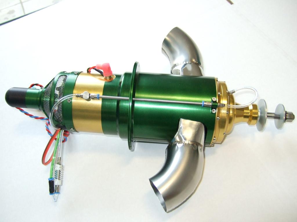
2 Wren 44 Kerosene Start Supplement This supplement is supplied to assist Wren 44 owners to install and operate the new Wren kerosene start system with Xicoy Au107K ECU. This system replaces propane start components except the valves which are retained. Propane tanks, flow controls, filling valves etc, are no longer required. The green propane feed pipe should be blanked off close to the engine. PLEASE NOTE If you have bought an engine from Wren Turbines with a kero start fitted, PLEASE DO NOT jump in and change the settings supplied as the engine will have already been carefully set up ready to run. Setting up the kero-system is straight forward but users are requested to take particular care in setting values to the ECU. The ECU allows access to all values held in the memory. Most should not need adjusting and customers are asked to refrain from making changes to these values as they may have a significant effect on the engine starting and operation. Those settings which access IS needed are described in the checklist. These notes are not intended to replace the existing instructions and users should refer to these for guidance on installation and operation. The installation assumes the engine is fully serviceable and is a current Wren 44 Gold unit. Contact us first if your engine is an earlier model. Fitting a kero-start system will not cure a poorly starting engine so be sure your engine is in good working order before fitting. If you are unsure of the suitability of your engine please contact Wren Turbines Ltd. All Wren 44 Turboprops and 44 Heli s are based on the 10Lb thrust Gold engine so if you have one of these this system will be suitable. The system requires a LiPo battery of 1800mAh or better. A C-rating of 20 or more is needed. The operation of the fuel pump is more critical in a kerostart system as the fuel pump must be able to reliably run at a slow power setting. For this reason we use a fuel pump made especially for small engines. Other pumps are not suitable. Operation of the two valves is also critical as rapid switching of these is used to regulate fuel flow at the starting, these components must be in perfect order. The brass type are suitable and have proved reliable. Fuel must be kept clean and free of water ingress even tiny amounts can make deposits on the pumps gears and spoil the valve seats and make successful kerosene starting impossible. Inspect your fuelling equipment and filters regularly and dispose and replace any fuel with water or particle inclusions. This manual and the pictures and data included are copyright of Wren Turbines Ltd and may not be used without their permission. Wren Turbines Ltd are at: Unit 19, Century Park Network Centre, Dearne Lane, Manvers, Rotherham, South Yorkshire, England. S63 5DE. Tel. +44 (0) Fax. +44 (0) info@wrenturbines.co.uk Wren 44 Kerostart Supplement Copyright Wren Turbines Ltd All rights reserved. Page 1
3 How does it work? The kerostart system is basically an alternative form of heating from the propane system used in gas start engines. Heating is achieved by igniting and burning a small amount of fuel using a small plug called the Burner. This is a small ceramic element enclosed in a stainless steel housing with a very small clearance around its tip. The housing fits the normal glowplug hole and uses the same glowplug cable. The element is heating by passing electrical current through it and its tip glows bright orange (voltage set in ( Glowplug Power ). Kerosene fuel is then pumped through the narrow gap next to the glowing element and it bursts into flame. This flame then provides enough heating in the combustion chamber to allow fuel to vapourize when passed down the vapourizer tubes in the normal way. The amount of fuel used for the burner is very small and the fuel pump is unable to run this slowly in a reliable way, so the solenoid valve supplying the burner switches on and off rapidly to help regulate the flow. The longer the valve stays open the more fuel passes and this is how the ECU controls the flow. The setting for this is important as too little flow and there will only be a small flame, but too much and the element may be cooled so much the fuel fails to ignite into flame. Also, if the engine is spinning too fast while the small flame is going it may blow the flame out so rpm must be carefully controlled ( Starter Power at Ignition and RPM Ignition Kero ). This stage is called Ignition. In the ECU, the amount of fuel fed to the burner is controlled by the function Pump Power Ignition Kero in the START menu and the engine speed after the burner has ignited, is controlled by RPM Ignition Kero. Once the ECU has seen enough temperature rise from the small flame it will begin pulsing the main fuel valve to the combustion chamber in addition to the burner - a very small amount initially so as to establish combustion properly. This stage is called Preheat. Functions used at this stage are RPM Preheat Kero (sets the rotor speed at this point) and Engine Preheat Fuel (amount of fuel allowed into chamber). Once the ECU has seen enough temperature rise (set in EGT End Preheat ) it will gradually increase the starter speed and main fuel valve opening time to increase the fuel flow to the main chamber and conversely reduce fuel flow to the burner until it is shut off completely. This stage is called Switchover. At switchover the fuel pump is driving at a new rate set by a number - Pump Start Point and the rate of increase of the starting is set by Pump Start Ramp and the initial %flow through the fuel valve is set by Engine Min Flow. This %flow and increasing rpm continues increasing as the engines accelerates up to the point where the fuel valve is 100% open display shows FuelRamp. The fuel pump power keeps rising until the starter is no longer needed ( RPM Off Starter ) and continues until the engine reaches the idle speed set. Note we have highlighted Pump Power Ignition Kero and Pump Start Point in red as these are the main adjustments needed to tune a new fuel pump or adjust for a worn one. Wren 44 Kerostart Supplement Copyright Wren Turbines Ltd All rights reserved. Page 2
4 Pump Igniter Valve Fuel tank Igniter Plug Fuel Valve Starter motor STARTER RPM sensor Temp sensor Data Terminal KERO VALVE GAS VALVE GLOW PUMP Xicoy Fadec Au-107K ECU BATTERY 7.4V 2cell LiPo Receiver Throttle signal Throttle In RPM TEMP Connection Schematic for Fadec Xicoy AU-107K ECU. Wren 44 Kerostart Supplement Copyright Wren Turbines Ltd All rights reserved. Page 3
 Wren kero burner 3mm ptfe burner feed pipe and inline connector 3mm T or Y connector 3mm fuel piping 2-cell LiPo")

5 Components required for 44 kerosene start installation: 44 Gold Engine (thrust, heli or turboprop) Xicoy AU-107K ECU (pre-programmed for 44 kerostart) 3-wire type Data Terminal Hausl ZP25M14 magnetically coupled fuel pump Two valves c/w 3mm push-in fittings, (brass type) Wren kero burner 3mm ptfe burner feed pipe and inline connector 3mm T or Y connector 3mm fuel piping 2-cell LiPo 1800mAh, 20C rating battery Quick start installation, mechanical: Position the fuel pump, ECU and valves. Place valves as close to engine as possible. Screw burner onto engine plughole using earth terminal above the banjo fitting. Rotate the burner feed into the direction to suit your install before tightening. Fit plug cap to burner nipple. Push on ptfe 3mm tube onto burner nipple and slide green gland nut over top and screw on firmly/gently. Connect inline 3mm fitting to end of burner ptfe tube. Connect a short (20mm) 4mm tube onto fuel pump inlet and longer 3mm tube to outlet. Push on Tygon feed from tank onto 4mm pump tube. Position T connector close to valve inlets and connect pump outlet to T inlet with 3mm tube. Connect T outlets to each valve with 3mm tube. Xicoy AU-107K ECU showing plug locations. See text for details on what plugs in where. Connect one valve output to engine fuel inlet with 3mm tube. Connect the other valve output to the burner feed fitting with 3mm tube. Wren 44 Kerostart Supplement Copyright Wren Turbines Ltd All rights reserved. Page 4
6 Quick start installation - electrical: Refer to the picture of the ECU on previous page for plug locations. Plug burner valve to the 2-pin socket marked as Gas valve on ECU (see top left). Plug engine fuel valve to adjacent 2-pin socket marked Fuel valve (extreme top left), note this label is on side of ECU. Plug in the receiver throttle signal wire from receiver to the plug marked Throttle input (see bottom right). Plug in the engine rpm sensor to the 3-pin plug marked RPM sensor (bottom right). Plug in the engine temperature probe to the 3-pin plug marked Thermocouple (bottom right). Plug in the glow/starter cable from the engine, using extension if fitted, (see top right). Plug in the battery/pump cable (top left). Leave the battery end unconnected at this stage. Plug in the data terminal (bottom left). A standard servo type extension cable can be fitted to the model to allow convenient access, if required. Setting up ECU (Engine Control Unit) Remove all rates, mixes and throttle travel settings in the transmitter. The setup assumes the use of a transmitter with manual trims. Digital trims and Throttle-Cut function. If you have a transmitter with digital trims you can simulate the trim up/down function using the Throttle Cut switch, which is usually a function switched through a toggle switch mounted on the transmitter (must not be spring loaded). Consult your radio manual for this function. Setting the ECU using the Throttle Cut function is done in the same way except that when trim-up is required you switch the Throttle Cut to off, and when trim-down is required, you switch to Throttle Cut on. For initial testing the normal digital trims can be used if you don t want to have to explore the Throttle Cut function just yet. The trim up/down function is used to switch the engine to ready to start and off, and would not normally be used to vary the idle rpm. Note - some transmitters may need throttle reversing - see later. As the display does not photograph well we have reproduced the display readings as a green box. Turn on the transmitter and receiver. On power-up the screen should come on and after a few seconds should stabilise to the opening screen and should show as right: Trim Low T=020 C RPM PW 000 (If the temp probe is not connected it will show as 0 C). T = ambient temp. Wren 44 Kerostart Supplement Copyright Wren Turbines Ltd All rights reserved. Page 5
 and scroll through the menus until you find the one showing : Transmitter adjust Enter The display will now change to: Stick Down Trim Up (Idle) Leaving the throttle stick in")
 button and the screen will change to: Press the + button to enter the radio setup screen.")
 Move the throttle trim (or switch the engine cut switch to on) and throttle stick back to zero and again press the + button.")
7 There are four buttons on Info Run the display. The buttons Start Radio are: -+. To scroll through the different screens use. The buttons - + are used to change the values stored. Press the Up button ( ) and scroll through the menus until you find the one showing : Transmitter adjust Enter The display will now change to: Stick Down Trim Up (Idle) Leaving the throttle stick in the minimum position, raise the throttle trim to the max position or switch Engine Cut switch to off, and again press the + button. Press the minus (-) button and the screen will change to: Press the + button to enter the radio setup screen. You should then see this screen: Stick Up Trim Up (Full power) On your transmitter, place the throttle stick and trim to maximum and press the + button to set the value into the ECU. The screen will now change to: Stick Down Trim Down (Stop) Move the throttle trim (or switch the engine cut switch to on) and throttle stick back to zero and again press the + button. The display should then show: Thrust curve: LINEAR Lower trim to zero. Now switch off the receiver. Turn the receiver on again, if you have done all the steps correctly the opening screen will show Trim Low and if you raise your trim to full it should change to Ready and a blue led will light on the ecu. If not, you will need to reverse the throttle channel on your transmitter and repeat the radio setup. This completes your radio set-up. It should only need doing again if the radio settings are changed or installation moved to another radio but it is worth rechecking periodically. Wren 44 Kerostart Supplement Copyright Wren Turbines Ltd All rights reserved. Page 6
8 Setting up to run engine: Turn on the receiver and verify the screen shows a reading. Go into the 3rd screen and enter the RADIO menu and perform the transmitter setup if not already completed. Connect the LiPo battery. Turn on fuel if you have fitted a shutoff tap between pump and valves (preferred position). Ensure trim and stick are at zero. Enter INFO menu and go down the entries until you get to test functions. Find Test/Prime Pump. Press On button to turn on fuel pump and watch fuel travel along from the tank to the engine. Press Off to stop. Go further down INFO menu to Prime Burner On Off. Press On button and watch fuel travel to burner, then press Off to stop. Do not prime longer as you risk pouring fuel into the engine which will cause a flaming start. Small bubbles in the pipes at this stage will not prevent a start, just delay it. Place the engine/plane into a suitable place and prepare for a start. Use helper if required to restrain model. Position fire extinguisher if you get into trouble place trim down, stick down immediately to halt the start. Then energise the starter by raising the stick to full to spin the engine up to clear. If you have a fire, position C02 extinguisher nozzle at engine intake and use short bursts to put out. Wren 44 Kerostart Supplement Copyright Wren Turbines Ltd All rights reserved. Page 7
9 Starting the engine. Turn on transmitter and receiver. Plug in display - screen shows Trim Low To initiate the start, raise trim to full, ((led in ECU lights and screen shows Ready ). Place stick to full and back down quickly. (Holding the stick at full will spin engine at full power can be used to cool down from a previous hot start or run) Starter will spin engine briefly and then power igniter (screen shows Glow Test then Burner On ). To initiate start without spinning engine raise trim to full, raise stick half way and back down. Igniter will heat and after some seconds starter will spin engine slowly, pump will turn on slowly, igniter valve ticking. If pump does not come on raise pump power ignition kero until it does. You should hear a pop and combustion starting in the engine and temperature rise on the display. (Screen shows Preheat ). If too gentle, increase preheat fuel. After some seconds engine speed and temp will increase, valve pulsing will speed up and the main fuel valve begin to open and engine begins accelerating towards idle. (Screen shows Switchover then Fuel Ramp ). If engine stops at switchover, increase pump start point until it continues. (Sometimes needs to be 50 or more). If the engine slows down or makes smoke at switchover, increase the value for min flow as the flow is not high enough to make a successful switchover. At the end of switchover, burner turns off at around 20,000rpm, and fuel ramp proper begins. Engine continues accelerating and starter turns off as it passes 30,000rpm. Engine arrives at 55,000rpm - idle, (screen shows Running ). You now have control of engine via throttle stick. At any time the start can be terminated by lowering stick and trim to zero. The throttle stick can then be used to switch the starter to clear/cool the engine. After running. After running or flight, raise rpm to 80,000rpm for ten seconds and lower stick and trim to zero for cooling. ECU will spin engine in short bursts until the temp reading goes below 100 C where it will stop. If temp rises above 100 C again ECU will spin the engine again until below 100 C. Once cooling is complete display shows Stop. You can turn off receiver and transmitter and disconnect LiPo battery, if this is the last run for a while, or you need to recharge. Never recharge a LiPo whilst installed in a model. Wren 44 Kerostart Supplement Copyright Wren Turbines Ltd All rights reserved. Page 8
10 Settings used in ECU. A Wren supplied kerostart engine package will already be adjusted for optimum ECU and pumps settings and should need little or no attention, so do not fiddle with the settings. As the fuel pump wears it may be necessary to adjust settings see later. An upgrade set of kerostart parts will have the ECU supplied pre-programmed with initial values but may need tuning to get clean and secure starting for the particular engine and install. Please note, no two installations will be truly identical so do not swap settings with a colleague with a similar engine as they will most likely not be compatible. If the fuel pump is replaced, new settings may be required as no two pumps have precisely the same characteristics. A problems checksheet follows in the next couple of pages. It lists common faults and the likely cures and hopefully will solve your problem quickly. Please use the checksheet before calling us it is there to help you to save time trouble and expense. If you find something not covered then of course mail us with a description and we will try to help you: info@wrenturbines.co.uk Please note, we can only help users with a kerostart issue on a Wren engine. ECU default values and adjusted settings: Item: Initial value: Your values: Pump start point Pump start ramp 004 Glow power 6.9v Low battery volts 6.0v Starter power at ignition 060 Starter power at fuel ramp 070 RPM point 100% starter power 25,000 RPM starter off 30,000 RPM reconnect starter 27,000 RPM Ignition kero 7,000 Pump power ignition kero Engine min flow % EGT end preheat C RPM preheat kero 12-14,000 RPM fuel ramp kero 20,000 Preheat fuel Ignition timeout sec s 24.5 *Items highlighted adjusted for fine tuning* DO NOT TWIDDLE WITHOUT REASON Wren 44 Kerostart Supplement Copyright Wren Turbines Ltd All rights reserved. Page 9
11 Problems Checklist: The usual problems associated with a kerostart installation can be narrowed to just two key items the Pump Start Point and the Pump Power Ignition Kero. Both of these can be trialled with the same number and are adjusted to suit each fuel pump fitted to the system. A tight or new pump will benefit from some running-in before fitting and this helps to settle the gears etc. The values may need to be raised considerably to get the initial settings to get the pump going. As the fuel pump loosens in service the values for these functions may then need reducing by a few points to make a start less aggressive. We present here some of the usual things encountered in the hope they clear up any problems you might see. The checklists are listed in the order in which problems may be encountered, ie setup and starting. It is not intended in this supplement to cover normal running problems as these would already be covered in the respective operators manuals. A detailed manual covering all the kerostart functions is available to download from Xicoy Electronica SL on Be sure to ask for the V10 kerostart manual (there is a choice of gas start too). Symptom Problem Action No reading on ECU display unit Transmitter stick down/trim up reads StickLo Temp reading incorrect or 0 Temp reading shows lower or negative figure on ignition No rpm indicated when engine is spun Kerosene does not ignite No kerosene ignition ECU shows GlowBad RX not switched on or RX battery discharged Display not connected properly Display malfunction ECU problem Throttle channel needs reversing, Thermocouple not connected to ECU ECU problem Thermocouple failure Thermocouple plug inserted wrong way round Rpm sensor plug inserted incorrectly Rpm sensor lead broken/chafed Rpm sensor malfunction ECU problem Glow power set too low Poor glow at igniter Plug partially blown ECU battery low Burner fuel too low Burner valve not operating Pump not turning Element blown / open circuit Verify connection and charge if necessary Ensure that display is plugged in the correct orientation Reverse channel on Tx (most Futaba s need this) Verify connection Ensure connector matches the label on the ECU Ensure connector matches the label on the ECU Remove source of chafing and repair/replace Check at least 6.8v in start menu - Glowpower Check connections / earth Replace element Charge Increase burner fuel (Pump Power Ignition Kero) Check valve inserted correctly into ecu Check pump for correct operation (use TEST/Prime PUMP in INFO) Replace element (call Wren for service replacement) Wren 44 Kerostart Supplement Copyright Wren Turbines Ltd All rights reserved. Page 10

12 Problems Checklist con t Symptom Problem Action Pump not connected Check wiring Fuel pump not running No or little temp rise on ignition Pump runs but no fuel delivered No or little rpm increase as fuel enters Pump jammed with foreign object No drive from ECU Insufficient burner fuel Temp probe not inserted into exhaust cone Fuel not reaching tank pickup Pump fault burner solenoid not opening Insufficient revs on starter motor Clutch slipping Air in fuel line Investigate operation and rectify (disconnect, run backwards to clear) Increase Pump Power Ignition Kero Insert 6mm Check clunk for blockage. Ensure fuel like is not kinked Check solenoid operation Check wiring to ECU Recharge ECU battery Replace O-ring Purge fuel lines and retry We hope you have found this supplement helpful and that you have enjoyed success in operation of your Wren 44 kerostart engine. Please note, all the items used in the kerostart system are available as individual spares no need to buy a whole new unit. The ceramic burner element is regarded as a long life component but as with all electrical devices can decide to give up without warning. If the screw-in centre section of the kero igniter is returned to us we can refit a new element for a small charge. Excessive flaming Engine overshoots at idle Engine slows or is stopped during start Trim down/shut off fuel immediately Residual fuel in engine Spin engine dry for 5 seconds to clear Engine min flow % too high Reduce 2 points and retry Insufficient revs on starter Recharge ECU battery Starter motor weak/inoperative Pump Start Point too high Lower by 2 points and retry Engine malfunction Return to dealer Normal problem until ECU settles down Aggressive starting Clear excess / lower Pump Start Ramp by 2 points and retry Air in fuel line causes late but ECU will correct itself and settle rapid start-up down Engine min flow set too low. Increase by 2 points and retry Interference to rpm pickup by Wild rpm reading burner wiring (usually), find and move. Check starter/burner wires are well twisted. Alternatively you can buy an extra one for holding as a spare in your flightbox so you never need to lose a flight due to an expired element! We are always pleased to get feedback from users and to take additions to this supplement to enhance the experience of others following the same pathway. Please send us any comments or suggestions for inclusion to info@wrenturbines.co.uk. Thank-you Wren Turbines Ltd (UK) Wren Turbines USA Feb 2012 Wren 44 Kerostart Supplement Copyright Wren Turbines Ltd All rights reserved. Page 11
Glow Plug for E Series Only
 Charging the Battery - Do not charge the battery, with a charger using negative discharge pulses, when connected to the ECU. This will destroy the electronics of the ECU. The only method is to disconnect
Table of contents. THE RADIO Operation & functions 18 Additional switch channel 18 Switch off automatic cool down 19
 Table of contents INTRODUCTION About Hornet 3 Connection diagram 3 THE SYSTEM The components 4 Power supply 4 Sensor installation 4 The power plugs/polarity 5 Starter 5 Glow plug 6 Porpane-/kerosene- valve
FADEC system - Autostart 06
 FADEC system - Autostart 06 Users Guide. Parlament, 13. 08358, Arenys de Munt, Barcelona,Spain E-mail: info@xicoy.com. Fax: +34 933 969 743 web: www.xicoy.com Copyright 2007, Xicoy Electronica SL. All
2016
 SUMMARY AND TURBINE DETAILS 1 WARRANTY, SAFETY NOTES, COMPOSED KIT 2 ECU CONNECTORS LAYOUT 3 STATUS DISPLAY 4 CONNECTION DIAGRAMM 5 MENU SETUP 6 MENU ADJUSTAMENT 7 SYSTEM AND MASTERMODE 8 CHECK LIST 9
OPERATION AND MAINTENANCE MANUAL
 OPERATION AND MAINTENANCE MANUAL INTRODUCTION JET CENTRAL produces the most advanced micro turbines available today: smaller, more powerful, faster acceleration, less fuel burn, lower temperatures, higher
OPERATION AND MAINTENANCE MANUAL
 Power Pack series OPERATION AND MAINTENANCE MANUAL 1 INTRODUCTION JET CENTRAL produces the most advanced micro turbines available today: smaller, more powerful, faster acceleration, less fuel burn, lower
Turbine engine user manual. ATJ SV series turbine
 Turbine engine user manual ATJ SV series turbine Copyright 2008. ATJ Turbine. All Rights Reserved Manual contents & design: Leading Jet Turbine Co., Ltd LEADING JET TURBINE Co., Ltd. ATJ TURBINES 1 Welcome!
Section 3 Technical Information
 Section 3 Technical Information In this Module: Engine identification Modes of operation Battery charging and heat manage operation Service and repair procedures Maintenance requirements Engine Identification
OPERATION AND MAINTENANCE MANUAL
 OPERATION AND MAINTENANCE MANUAL INTRODUCTION JET CENTRAL produces the most advanced micro turbines available today: smaller, more powerful, faster acceleration, less fuel burn, lower temperatures, higher
Items required:- Old Propane Gas Gun, High Pressure regulator, High pressure gas pipe and pipe clips, 12V battery, Propane gas, Tools Etc.
 CONVERSION INSTRUCTIONS FOR GAS GUN CONVERSION KIT MKIII & MKIV Items required:- Old Propane Gas Gun, High Pressure regulator, High pressure gas pipe and pipe clips, 12V battery, Propane gas, Tools Etc.
IMPORTANT FITTING INSTRUCTIONS PLEASE READ THESE INSTRUCTIONS BEFORE FITTING YOUR TURBO. FAILING TO FOLLOW THEM COULD INVALIDATE THE WARRANTY.
 IMPORTANT FITTING INSTRUCTIONS! PLEASE READ THESE INSTRUCTIONS BEFORE FITTING YOUR TURBO. FAILING TO FOLLOW THEM COULD INVALIDATE THE WARRANTY. 1WHY DID THE LAST TURBO FAIL? Turbochargers are very reliable:
Begin to Use The New ESC: Before use the new ESC please carefully check every connections are correct or not. Yellow motor wire B Blue motor wire A
 HIMOTO ZTW Brushless Electronic Speed Control for car or truck Thank you for purchasing ZTW Brushless Electronic Speed Controller(ESC). The ZTW electronic speed control (ESC) is specifically designed for
Glow Plug Driver. What is a Glow Plug Driver?
 What is a? A is essentially an electronic servo that controls a power supply that allows you to turn your glow plug on and off from an on board battery. The Glow Driver plugs into your receiver either
SHIFNOID WIRING DIAGRAM FOR a B&M PRO RATCHET with SN5070 SOLENOID KIT
 SHIFNOID WIRING DIAGRAM FOR a B&M PRO RATCHET with SN5070 SOLENOID KIT IF YOUR RPM SWITCH OR TIMER SUPPLIES "NORMALLY OPEN GROUND" (SHIFNOID OR MSD) USE THIS DIAGRAM IF YOUR RPM SWITCH OR TIMER SUPPLIES
(Designed & Manufactured by RC EXPLORER TEAM) XPS Brushless Speed Control System User Guidelines
 XPS Brushless Speed Control System User Guidelines") (Designed & Manufactured by RC EXPLORER TEAM) XPS Brushless Speed Control System User Guidelines 1. Technical /Specifications: Model: XPS- Pro XPS-Sport XPS-EL Continuous current: 140A 70A 35A Burst Current
(Designed & Manufactured by RC EXPLORER TEAM) XPS Brushless Speed Control System User Guidelines 1. Technical /Specifications: Model: XPS- Pro XPS-Sport XPS-EL Continuous current: 140A 70A 35A Burst Current
Subject Underhood G System Error Codes and Symptoms System or Parts affected
 System or Parts affected Index Underhood70G (V90Gxxx) System or Parts affected... 1 Overview... 1 Identifying your System... 1 Retrieving Logged Error Messages... 1 Error Messages... 3 Error Message Table...
(Designed & Manufactured by RC EXPLORER TEAM) Radon V2 series Brushless Speed Control System User Guidelines
 Radon V2 series Brushless Speed Control System User Guidelines") (Designed & Manufactured by RC EXPLORER TEAM) Radon V2 series Brushless Speed Control System User Guidelines 1. Technical /Specifications: Model: Radon Pro V2 Radon Pro V2 1S Radon Sport V2 Continuous
(Designed & Manufactured by RC EXPLORER TEAM) Radon V2 series Brushless Speed Control System User Guidelines 1. Technical /Specifications: Model: Radon Pro V2 Radon Pro V2 1S Radon Sport V2 Continuous
SWIWIN Turbines. SW Brushless Series. Kero Start Full Autostart with Auto-Restart Operations Manual
 SWIWIN Turbines SW Brushless Series Kero Start Full Autostart with Auto-Restart Operations Manual Table of Contents Introduction... 3 Non- Disclaimer... 3 Safety First... 3 Warning to Bystanders... 4 Fire
MPI MX-9900 SUPER GLOW On-board Glow Driver
 MPI SUPER GLOW On-board Glow Driver Congratulations on your purchase of the SUPER-GLOW on-board glow driver. This an advanced on-board glow driver offering unique features. is very different from other
PHOENIX HV Features of the Phoenix HV-45 : 2.3 Connecting the Motor. 2.4 Reversing Rotation. 2.5 Connecting the Receiver
 PHOENIX HV -45 1.0 Features of the Phoenix HV-45 : Extremely Low Resistance (.003 ohms) High rate adjustable switching (PWM) Up to 45 Amps continuous current Dual Opto-Coupled (No BEC) Up to 36 cells or
SWIWIN Turbines. SW Series. Kero Start Full Autostart with Auto-Restart Operations Manual
 SWIWIN Turbines SW Series Kero Start Full Autostart with Auto-Restart Operations Manual Table of Contents Introduction... 3 Non- Disclaimer... 3 Safety First... 3 Warning to Bystanders... 4 Fire extinguishers...
INSTALLATION GUIDE Table of Contents
 CT-3100 Automatic transmission remote engine starter systems. What s included..2 INSTALLATION GUIDE Table of Contents Door lock toggle mode..... 4 Notice...2 Installation points to remember. 2 Features..2
Warning! Before continuing further, please ensure that you have NOT mounted the propellers on the MultiRotor.
 Mission Planner Setup ( optional, do not use if you have already completed the Dashboard set-up ) Warning! Before continuing further, please ensure that you have NOT mounted the propellers on the MultiRotor.
The Combustex Pilot Pro 800 Pilot Burner Assembly with Ignition & Flame Failure Monitor
 OPERATIONS MANUAL The Combustex Pilot Pro 800 Pilot Burner Assembly with Ignition & Flame Failure Monitor Safe, reliable ignition and flame failure protection combined with a proven, completely self-powered
Features: Enhanced throttle response, excellent acceleration, strong brakes and throttle linearity. Using LED program card to make adjustments.
 Thank you for purchasing the ZTW Brushless Electronic Speed Controller (ESC). The ZTW 1:10 Scale BEAST Series ESC is specifically designed for operating 4 Pole Sensorless brushless motors. This is a high
PHOENIX Features of the Phoenix-25 : 2.3 Connecting the Motor. 2.4 Reversing Rotation. 2.5 Connecting the Receiver
 Warning! High power motor systems can be very dangerous! High currents can heat wires and batteries, causing fires and burning skin. Follow the wiring directions carefully! Model aircraft equipped with
Kero Start Full Autostart with Auto-Restart Operations Manual
 Swiwin Turbines USA 9858 Baldwin Place El Monte, CA 91731 Website: www.swiwinturbines.com Email: service@swiwinturbines.com Phone: (602) 818-8598 Business Hours: Mon-Sun 9AM-5PM Swiwin Turbines SW Brushless
Version 1.4 Operating instructions Czech Republic
 Version 1.4 Operating instructions Czech Republic Please check updates of operating instructions at www.rotomotor.cz, that your engine has still the best care. (can happen important changes that will lead
SP4 DOCUMENTATION. 1. SP4 Reference manual SP4 console.
 SP4 DOCUMENTATION 1. SP4 Reference manual.... 1 1.1. SP4 console... 1 1.2 Configuration... 3 1.3 SP4 I/O module.... 6 2. Dynamometer Installation... 7 2.1. Installation parts.... 8 2.2. Connectors and
Thank you for buying an Alien Power System (APS) product. WARNING: Product Features:
 product. WARNING: Product Features:") Thank you for buying an Alien Power System (APS) product. Please follow the instructions to program your controller. Incorrect handling may cause damage to the controller and cause injury to yourself and
Thank you for buying an Alien Power System (APS) product. Please follow the instructions to program your controller. Incorrect handling may cause damage to the controller and cause injury to yourself and
INSTRUCTIONS. #82028 Diesel Nitrous System. Thank you for choosing ZEX products; we are proud to be your manufacturer of choice.
 1 INSTRUCTIONS #82028 Diesel Nitrous System Thank you for choosing ZEX products; we are proud to be your manufacturer of choice. Why our nitrous system is better: 2 Performance enthusiasts know the potential
SHIFNOID WIRING DIAGRAM
 SHIFNOID WIRING DIAGRAM FOR a HURST QUARTER STICK with a SN5055H THREE SPEED SOLENOID KIT IF YOUR RPM SWITCH OR TIMER SUPPLIES "NORMALLY OPEN GROUND" (SHIFNOID OR MSD) USE THIS DIAGRAM 86 NOT USED 87a
SWIWIN Turbines. SW Brushless Series. Kero Start Full Autostart with Auto-Restart Operations Manual
 SWIWIN Turbines SW Brushless Series Kero Start Full Autostart with Auto-Restart Operations Manual Table of Contents Introduction... 5 Non- Disclaimer... 5 Safety First... 5 Warning to Bystanders... 6 Fire
Start Up Instructions for the Kiln, Page 1 of 2
 Start Up Instructions for the Kiln, Page 1 of 2 1. Turn the Main Breaker at the right side of the panel on. 2. Press the orange [Control Power On] push button. It will light up when pressed. 3. If the
PF3100 TROUBLESHOOTING SOLUTIONS TO COMMON PROBLEMS. v1.1 Revised Nov 29, 2016
 PF3100 TROUBLESHOOTING SOLUTIONS TO COMMON PROBLEMS v1.1 Revised Table of Contents 1 Common Alarms and Warnings... 1 2 Common Issues... 6 2.1 Communication problems... 6 2.1.1 Controller communication
Tri-Spark Ignition System Installation Triple Cylinder TRI-0001
 Tri-Spark Ignition System Installation Triple Cylinder TRI-0001 There are potentially lethal high voltages produced at the ignition coils and spark plugs, therefore every precaution must be taken to prevent
1 Function Scope of Delivery Mounting Electrical Connections Initial Setup Troubleshooting...
 Elektronik Sachse MHP GmbH & Co. KG Installation Manual Digital Ignition ZDG 3.23 (Ducati Mille) Item: Z73 version: f4feb00 Contents 1 Function.......................................................................
PHOENIX Features of the Phoenix-10 : 2.3 Connecting the Motor. 2.4 Reversing Rotation. 2.5 Connecting the Receiver
 Warning! High power motor systems can be very dangerous! High currents can heat wires and batteries, causing fires and burning skin. Follow the wiring directions carefully! Model aircraft equipped with
Installation, Operating, Maintenance and Safety Instructions for CW332 Pressurised water system for boats 24 volt d.c.
 24V DC-CW332 DOC531/11 Installation, Operating, Maintenance and Safety Instructions for CW332 Pressurised water system for boats 24 volt d.c. To obtain the best performance from your Pressurised water
Battery cell. User Current(A) NiXX/Lipo. 20A 20A 30A 5-12 NC \ 2-4 Lipo 20 5V / 2A 23 x 33 x 6 yes
 NiXX/Lipo. 20A 20A 30A 5-12 NC \ 2-4 Lipo 20 5V / 2A 23 x 33 x 6 yes") 1 Wires Connection: The electronic speed controller can be connected to the motor by soldering directly or with high quality connectors. Always use new connectors, which should be soldered carefully to
1 Wires Connection: The electronic speed controller can be connected to the motor by soldering directly or with high quality connectors. Always use new connectors, which should be soldered carefully to
ESC. Brushless Controller. Receiver
 ESC instruction Wires Connection: The electronic speed controller can be connected to the motor by soldering directly, or with high quality connectors. Always use new connectors, which should be soldered
Purging Air From Divider Block Lubrication Systems
 FROST ENGINEERING SERVICE Purging Air From Lubrication Systems A D I V I S I O N O F G E C S E Y S A L E S & S E R V I C E DESCRIPTION Divider block lubrication systems operate correctly only when all
Mercury HP gas-turbine. January 2008
 AMT Netherlands b.v. Heistraat 89 NL-571 HJ Helmond Netherlands/Holland Tel: int+31 492 54581 Fax: int+31 492 55379 Http: //www.amtjets.com Email: email@amtjets.com Mercury HP gas-turbine. January 28 E-start
D3000. Troubleshooting Guide
 Page 1 of 6 17486-00 Rev B s3 April 2009 Contents Description Page Safety.. 3 Introduction 3 Standard External Controls, Indicators and Normal Alarm Conditions 3 Troubleshooting Table.. 4 Unable to program
Service Bulletin. (This bulletin and all other active bulletins are downloadable from our website at
 Bulletin 00--ABDE Service Bulletin (This bulletin and all other active bulletins are downloadable from our website at www.frymaster.com/parts_service.) Bulletin 00--ABDE Page of + Worksheets Date: 0//00
30A ESC Manual. Specification: Burst
 30A ESC Manual Wires Connection: The speed controller can be connected to the motor by soldering directly or with high quality connectors. Always use new connectors, which should be soldered carefully
ECT Display Driver Installation for AP2 Module
 ECT Display Driver Installation for AP2 Module Overview The ECT Display Driver is a small module with a removable wire harness that mounts behind the driver's foot well cover. All wiring connections are
Innovative Racing Electronics
 MPS Fast FI Mixture Control Installation Instructions The MPS Fast FI Mixture Control P/N 1-0337 is a simple means to adjust the fuel curves on your fuel-injected motorcycle. This allows for tuning after
Please check our application list to see if we have a specific Harness Kit available for your motorcycle.
 GIpro X-type Install Guide for GPX-WSS Harness Kit Compatibility: This universal harness kit includes a Wheel Speed Sensor and will fit all motorcycles and vehicles which have electronic ignition system.
Building Instructions Upside Variable Pitch Prop System
 Building Instructions Upside Variable Pitch Prop System it s tim o e t fly! Thank you for buying our revolutionary UPSIDEDOWN VP-Prop System! Experience a new dimension in 3D performance. Assembly and
2.0 Burner Operating Parameters and Requirements
 ECLIPSE INFORMATION GUIDE Silicon Carbide Radiant Auto-Recupes Info 322 2/99 WARNING Handle silicon carbide tubes carefully. Do not drop them or hammer on them. Although they feature excellent mechanical
Toyota GT86 / FRS / Subaru BRZ Stage 1 Tuning Kit
 Mill Road om 04 598300 Toyota GT86 / FRS / Subaru BRZ Stage 1 Tuning Kit Fitting Instructions - 20043610 Author: Matthew Feasey Terms and Conditions Copyright Cosworth Ltd Kit contents: 3 exhaust system
Peugeot 106 Citroen Saxo Gear Linkage Push Rods 3pc kit with grease seals x 2452/e1 Repair Fix Kit Instruction Install Guide
 Peugeot 106 Citroen Saxo Gear Linkage Push Rods 3pc kit with grease seals 245283 + 2 x 2452/e1 Repair Fix Kit Instruction Install Guide by x8rltd on August 6, 2015 Intro: Peugeot 106 Citroen Saxo Gear
16000SIII Automatic Grease System
 Manual # 99905495 16000SIII Automatic Grease System Effective 20120716 IOWA MOLD TOOLING CO., INC. PO Box 189 Garner, IA 50438 Tel: 641-923-3711 FAX: 641-923-2424 Website: http://www.imt.com Copyright
CPi. CoiL PACK IGNiTioN FOR AViATiON. For 4,6 and 8 cylinder 4 stroke applications. Please read the entire manual before beginning installation.
 1 CPi CoiL PACK IGNiTioN FOR AViATiON Coil pack (4 cylinder) Coil pack (6 cylinder) For 4,6 and 8 cylinder 4 stroke applications. Please read the entire manual before beginning installation. Software version
SHIFNOID WIRING DIAGRAM FOR a B&M PRO RATCHET with SN5070 SOLENOID KIT
 SHIFNOID WIRING DIAGRAM FOR a B&M PRO RATCHET with SN5070 SOLENOID KIT IF YOUR RPM SWITCH OR TIMER SUPPLIES "NORMALLY OPEN GROUND" (SHIFNOID OR MSD) USE THIS DIAGRAM IF YOUR RPM SWITCH OR TIMER SUPPLIES
Installation Instructions Diesel Nitrous System (#82028)
") Installation Instructions Diesel Nitrous System (#82028) Thank you for choosing ZEX. If at any time you have questions regarding this or any of our products, please call our Nitrous Help support line at
Installation Instructions Diesel Nitrous System (#82028) Thank you for choosing ZEX. If at any time you have questions regarding this or any of our products, please call our Nitrous Help support line at
Model 1:8 Beast-ZTWSS120A 1:8 Beast-ZTWSS150A. PN#Model Cont.Current 120A 150A. Burst Current 760A 1080A
 Alien Power System BEAST Series Sensored/Sensorless Brushless ESC for 1:8 scale Car or Truck Thank you for purchasing the Alien Power System Brushless Electronic Speed Controller (ESC). The Alien Power
Asynchronous Restriking CDI 2 channel
 Asynchronous Restriking CDI 2 channel Parts List ARC-2 module Decals Power Cable Fuse Specifications Operating Voltage: 8-20V Operating Current: Max Operating RPM: Ambient Temp range: Ignition inputs:
Wiring Main Power connector constant 12V power
 DHC-2000 Digital Height Control System Introduction This control system can be connected to a display module and height sensors or pressure senders to allow monitoring and control of all four corners and
INSTRUCTIONS. #82044 Race Diesel Nitrous System
 INSTRUCTIONS #82044 Race Diesel Nitrous System Thank you for choosing ZEX products; we are proud to be your manufacturer of choice. Kit Parts List Description Qty. Description Qty. Nitrous Solenoid 2.088
USER MANUAL BRUSHLESS SPEED CONTROLLER S5-RTR ESC S5A-RTR ESC RC CARS & TRUCKS
 USER MANUAL BRUSHLESS SPEED CONTROLLER S5-RTR ESC S5A-RTR ESC RC CARS & TRUCKS Declaration Thanks for purchasing our Electronic Speed Controller (ESC). High power system for RC model can be very dangerous,
Throttle Setup by Jason Priddle
 Throttle Setup by Jason Priddle This article is written around JR Radio convention. The numbers noted are for illustrative purposes, and the same principles apply to all radios Ever feel like all your
CRX Turbines. SW Brushless Series. Kero Start Full Autostart with Auto-Restart Operations Manual
 CRX Turbines SW Brushless Series Kero Start Full Autostart with Auto-Restart Operations Manual Table of Contents Introduction... 4 Non- Disclaimer... 4 Safety First... 4 Warning to Bystanders... 5 Fire
PHOENIX ENIX Features of the Phoenix-60 : 2.3 Connecting the Motor. 2.4 Reversing Rotation. 2.5 Connecting the Receiver
 PHOENIX ENIX-60 Warning! High power motor systems can be very dangerous! High currents can heat wires and batteries, causing fires and burning skin. Follow the wiring directions carefully! Model aircraft
Dealing with customer concerns related to electronic throttle bodies By: Bernie Thompson
 Dealing with customer concerns related to electronic throttle bodies By: Bernie Thompson In order to regulate the power produced from the gasoline internal combustion engine (ICE), a restriction is used
AFT mid drive kit Trouble shooting guide For 24v to 48V Kelly Controller KBS 48101L-L 100 A peak
 Date: 2016-13-1 AFT mid drive kit trouble shooting guide Rev 1.7 Page 1 of 17 AFT mid drive kit Trouble shooting guide For 24v to 48V Kelly Controller KBS 48101L-L 100 Table of Contents 1. Safety... 2
Here below is a technical description on how to perform a complete cleaning and restoration of a PETROMAX CP.
 Here below is a technical description on how to perform a complete cleaning and restoration of a PETROMAX 829 500CP. Preface The description below is based on the work I did and the experiences I had during
Mash Tun / RIMS Tube Controller
 Mash Tun / RIMS Tube Controller 1 Your new mash tun / RIMS Tube controller Thanks for buying your controller from us!!! Your controller is based on the MYPIN TA4 series PID controller. Unlike cheap REX
BSR Magic Box Digital ignition control for 4, 6, or 8 cylinder engines
 BSR BSR Magic Box Digital ignition control for 4, 6, or 8 cylinder engines Features Digital Advance The main feature of the Magic Box is the digital advance that replaces conventional weights and springs.
3/6/16 Tetrix first build robot instructions J. La Favre
 Figure 1 mount for Omni wheels - make two of these Figure 2 mount for Omni wheels, add bushing and tighten set screw of axle collar set screw should be tightened down on flat part of axle 1 Figure 3 Insert
Serial adapter 1.0 V10 Fadec to serial comunications
 Serial adapter 1.0 V10 Fadec to serial comunications Users Guide. Torrent d en Puig, 31. 08358, Arenys de Munt, Barcelona,Catalonia,Spain E-mail: info@xicoy.com. Fax: +34 933 969 743 web: www.xicoy.com
Features: Enhanced throttle response, excellent acceleration, linearity and driveability
 120A/150A ESC X-Car 120A/150A Series Sensored/Sensorless Brushless ESC for 1:8 scale Car or Truck Thank you for purchasing the X-Car Brushless Electronic Speed Controller (ESC). The X-Car 1:8 Scale 120A/150A
FIRE PHOENIX RADIO CONTROLLED AIRPLANE
 FIRE PHOENIX RADIO CONTROLLED AIRPLANE ASSEMBLY AND OPERATION INSTRUCTIONS YIN YAN MODEL TECH. MFT. 1 SPECIFICATIONS Material EPO Plane Battery Li-Po 1300mAh 11.1V Radio 4 Channel Wing Span 1200mm Length
Modulating Furnace Information. Warning on Meter Setting - Read First!
 Modulating Furnace Information Pressure Transducer Pressure DC Volts 0.00" 0.25 0.20" 0.63 0.25" 0.72 0.30" 0.82 0.35" 0.91 0.40" 1.00 0.45" 1.09 0.50" 1.19 0.55" 1.28 0.60" 1.38 0.65" 1.47 0.70" 1.56
Shotgun Double Barrel HPFP install guide
 Shotgun Double Barrel HPFP install guide Thank you for your purchase of the VTT Shotgun Double Barrel HPFP upgrade! First thing to do when you open your box is to make sure all parts are in their respective
Electric Landing Gear controller P14
 Electric Landing Gear controller P14 Users Guide Pahl Mechanische Fertigung, Gewerbepark Str.10, 4615 Holzhausen, Austria E-mail: info@pahl-mf.com. Tel: +43664 23 99 122 web: www.pahl-retracts.com UID:
Thank you for purchasing PA Quantum Pro Electronic Speed Controller (ESC)
") Thank you for purchasing PA Quantum Pro Electronic Speed Controller (ESC) High power systems for RC model can be very dangerous and we strongly suggest that you read this manual carefully. Precision Aerobatics
Thank you for purchasing PA Quantum Pro Electronic Speed Controller (ESC) High power systems for RC model can be very dangerous and we strongly suggest that you read this manual carefully. Precision Aerobatics
Minuteman International s Trouble Shooting the Kawasaki 17 HP Engine Engine Will Not Start.
 Minuteman International s Trouble Shooting the Kawasaki 17 HP Engine Instructions: Follow these steps until the problem is resolved Engine Will Not Start. (Battery is good and engine is cranking) 1. Do
SERVICE SHOP NOTES. Use ohmmeter to check the resistance between the leads.
 SERVICE SHOP NOTES LIMA MAC SELF VOLTAGE REGULATED GENERATORS Troubleshooting Tips Symptom: Engine bogs down or stalls even at no load. Problem: Main stator has one or more taps wound or connected incorrectly.
FUEL OIL BURNERS. By Mark Butterfield March 09
 FUEL OIL BURNERS By Mark Butterfield March 09 INTRODUCTION The history of burners dates back to the early shipping days, when fuel oil first started replacing coal as the ships primary fuel source. Since
PHOENIX Amp Brushless Sensorless Speed Control. 1.0 Features of the Phoenix-25 : 2.3 Connecting the Motor. 2.4 Reversing Rotation
 1.0 Features of the Phoenix-25 : Extremely Low Resistance (.013 ohms) High rate (7 KHz) switching (PWM) Up to 25 Amps continuous current with proper air flow, 35 amps surge Five to eight cells with four
EC200 ELECTRONIC CONTROL SYSTEM
 1 INTRODUCING THE EC200 ELECTRONIC CONTROL SYSTEM With the use of new technology and an innovative approach to user interfacing, the EC200 Power Control System provides a complete control solution for
Instructions for SAITO FA-200R3 (AAC) 4-Stroke Engine
 4-Stroke Engine") Instructions for SAITO FA-200R3 (AAC) 4-Stroke Engine We would like to express our sincere thanks for your purchase of the SAITO FA-200R3 engine. Please read our instructions carefully and treat your engine
Instructions for SAITO FA-200R3 (AAC) 4-Stroke Engine We would like to express our sincere thanks for your purchase of the SAITO FA-200R3 engine. Please read our instructions carefully and treat your engine
Rover SD1 Efi System Fuel Supply Components - Explanation and Testing of the Fuel Pump, Filter and Fuel Pressure Regulator
 Rover SD1 Efi System Fuel Supply Components - Explanation and Testing of the Fuel Pump, Filter and Fuel Pressure Regulator Introduction Some of the notes here are repetitious in order to review the components
RM moveit. Instruction Manual. Notebus -IC. Notebus + Notebus (LAP16-17H IC) (LAP16-17H EPM) (LAP16-17H B)
 (LAP16-17H EPM) (LAP16-17H B)") RM moveit Instruction Manual Notebus Notebus + Notebus -IC (LAP16-17H B) (LAP16-17H EPM) (LAP16-17H IC) RM moveit Instruction Manual The RM moveit (Bretford LAP16-17H) is specifically designed for the
RM moveit Instruction Manual Notebus Notebus + Notebus -IC (LAP16-17H B) (LAP16-17H EPM) (LAP16-17H IC) RM moveit Instruction Manual The RM moveit (Bretford LAP16-17H) is specifically designed for the
Advanced Troubleshooting Guide Snorkel V Battery Charger Rev 0 3JAN07
 Advanced Troubleshooting Guide Snorkel 3050097 24V Battery Charger Rev 0 3JAN07 1. How It Works: The 3050097 charger converts AC voltage to DC voltage, then uses high frequency to re-convert it to DC voltage/current
Introduction. Drenth Motorsport Gearboxes Fleuweweg AG Enter The Netherlands Phone: +31 (0) Fax: +31 (0)
 Fax: +31 (0)") 25.03.0023 Introduction The display unit comes with a software application. With the software application information shown on the display can be adjusted. There are different modes to adjust: the shape
25.03.0023 Introduction The display unit comes with a software application. With the software application information shown on the display can be adjusted. There are different modes to adjust: the shape
ACE Turbine instruction manual
 ACE Turbine instruction manual Limited warranty Turbojet engine running life,depend operating environment, operating methods have a direct relationship, turbojet engine used the most compact structure
Pierburg Intake Inlet Manifold Swirl Flap Blank Blanking Removal Repair Kit De-flap Kit Caps Delete Bungs
 Pierburg Intake Inlet Manifold Swirl Flap Blank Blanking Removal Repair Kit De-flap Kit Caps Delete Bungs by x8rltd on February 23, 2016 Intro: Pierburg Intake Inlet Manifold Swirl Flap Blank Blanking
User Manual. Brushless Speed Controller XERUN 80A/150A. Copyright 2009 Hobbywing Technology Co., Ltd. All Rights Reserved
 User Manual Brushless Speed Controller XERUN 80A/150A Copyright 2009 Hobbywing Technology Co., Ltd. All Rights Reserved CONTENTS DECLARATION FEATURES SPECIFICATIONS BEGIN TO USE THE NEW ESC PROGRAM THE
Arrow Shark TS760-Marine Onboard E-Starter. Owner Manual
 Arrow Shark TS760-Marine Onboard E-Starter Owner Manual The TS760-Marine Onboard E-Starter has concluded years of experience Arrow Shark has on RC boat onboard E-Starter, it will work for about all brands
Main 20 A fuse has blown (2) Connector has come off PCB
 Connector has come off PCB") ELECTRICAL FAULT FINDING OMS TRACTORS C & A from September 00 D&K series from April 00 JCB from Jan 00 Note: This Bulletin must be used in conjunction with the correct wiring diagram for the Tractor being
ELECTRICAL FAULT FINDING OMS TRACTORS C & A from September 00 D&K series from April 00 JCB from Jan 00 Note: This Bulletin must be used in conjunction with the correct wiring diagram for the Tractor being
Model 2300JL Installation Guide
 Model 2300JL Installation Guide POWER ACCESS CORPORATION 4 HERSHEY DRIVE, DOCK 4 ANSONIA, CT 06401 800-344-0088 WEBSITE: www.power-access.com EMAIL: salesinfo@power-access.com 1 STANDARD PARTS MODEL 2300JL
Starting up hydraulic systems
 General / Installation A hydraulic system that operates economically, safely, and trouble-free requires careful planning, as well as proper installation and start-up. Conscientious maintenance has a considerable
Street-Blaster 150i-TDI Dry Nitrous System - Export
 Street-Blaster 150i-TDI Dry Nitrous System - Export 01302 834343 www.noswizard.com Table of Contents List of Components 1 Nitrous Bottle Installation 2 Pipe Fitting Instructions 3 Nitrous Supply Pipe Routing
Model 2300DL Installation Guide
 Model 2300DL Installation Guide POWER ACCESS CORPORATION 4 HERSHEY DRIVE, DOCK 4 ANSONIA, CT 06401 800-344-0088 WEBSITE: www.power-access.com EMAIL: salesinfo@power-access.com 1 STANDARD PARTS MODEL 2300DL
AS RW BEC TRUCK LIPO User Manual ver 1.00
 ` To Receiver AS-12-40 RW BEC TRUCK LIPO User Manual ver 1.00 5-12 Cell 40 A For/Rev 2 A BEC Batt - Motor- Reverse Light Batt + Brake Light Motor+ Features: Operating Voltage: 5-12 Nimh/Nicad Cells or
Galileo with wifi RADIO CONTROLLED QUAD-COPTER
 Galileo with wifi TM RADIO CONTROLLED QUAD-COPTER FEATURING: 1. Four-Rotor design allows great speed and maneuverability for both Indoor and Outdoor use. 2. Built-in 6-axis Gyro ensures excellent stability.
SAVANNAH EI & DELUXE SYSTEM TROUBLE SHOOTING GUIDE
 SAVANNAH EI & DELUXE SYSTEM TROUBLE SHOOTING GUIDE ***PLEASE MAKE SURE TO LEARN THE REMOTE TO THE SYSTEM (REFER TO PG 6) AND CHECK THE BATTERIES FIRST!!! (American Flame AF-4000 Series) Intermittent Pilot