Thank you for purchasing PA Quantum Pro Electronic Speed Controller (ESC)
|
|
|
- Logan Pearson
- 6 years ago
- Views:
Transcription
1 Thank you for purchasing PA Quantum Pro Electronic Speed Controller (ESC) High power systems for RC model can be very dangerous and we strongly suggest that you read this manual carefully. Precision Aerobatics have no control over the use, installation, application, or maintenance of these products, thus no liability shall be assumed nor accepted for any damages, losses or costs resulting from the use of this item. Any claims arising from the operating, failure or malfunctioning etc. will be denied. We assume no liability for personal injury, property damage or consequential damages resulting from our product or our workmanship. As far as is legally permitted, the obligation for compensation is limited to the invoice amount of the product in question. Specification: Quantum 30 Pro Quantum 45 Pro Quantum 70 Pro Continuous current 30A 45A 70A Burst Current (<10s) 35A 55A 85A Switching BEC Output (continuous/burst) 5.6V/3A (continuous) 3.8A (burst) 5.6V/4A (continuous) 6A (burst) 5.6V/4A (continuous) 6A (burst) LiPo 2-4 Cells 2-5 Cells 2-6 Cells NiMh/NiCd 6-12 Cells 6-14 Cells 6-18 Cells Note: The PA Quantum Pro line has a powerful switching voltage regulator chip which supports the high torque micro servos in the most demanding load-conditions imposed during aggressive 3D aerobatics, providing bulletproof reliability. In this form of flying the servos actuating oversized control surfaces and may stall momentarily under extreme aerodynamic loads. These loads may cause most low and medium power BECs to overheat and shutdown resulting in catastrophic loss of control. The Quantum Pro ESC s high power SBEC has been specifically designed for extreme aerobatics and therefore has the capability to support the higher momentary peak loads to eliminate the possibility of unwanted shutdowns. This high power SBEC is also capable of supporting continuous simultaneous multiple servo operations typically found in CCPM equipped hardcore 3D E-helicopters. The higher and stable SBEC voltage also reduces the possibility of receiver brownouts that occasionally occur on some 2.4GHz receivers in instances where conventional linear BECs are subjected to high servo loads causing the BEC voltage to drop below the voltage threshold required by the 2.4GHz receiver. Features: Extremely low internal resistance Super smooth and accurate throttle linearity Safety thermal over-load protection Auto throttle shut down in signal lose situation Supports high RPM motors Power arming protection (prevents the motor from accidentally running when switched ON) NEW advanced programming software Powerful and reliable switching BEC (Battery Eliminator Circuit) New large high efficiency designed heat sink Our ESC allows you to program all functions to fit your specific needs, which makes it very efficient and user friendly: 1. User programmable brake setting (we recommend using brake for only folding props applications) 2. User programmable battery type (LiPo or NiCd/NiMh) 3. User programmable low voltage cutoff setting 4. User programmable factory default setup restore 5. User programmable switching frequency 6. User programmable low voltage cutoff type (power reduction or immediate shutdown) 7. User programmable timing settings (to enhance ESC efficiency and smoothness) 8. User programmable soft acceleration start ups (for delicate gearbox and helicopter applications) 9. User programmable motor rotation (clockwise\counterclockwise) 10. User programmable governor mode (for helicopter applications)
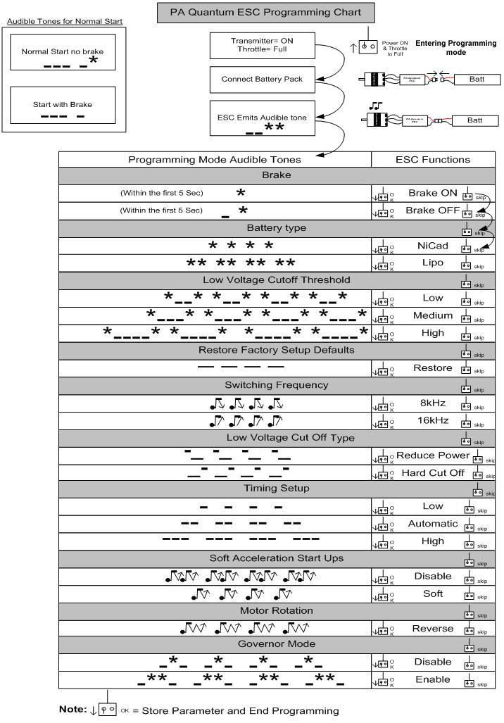
2 Wiring Diagram: Settings: 1. Brake: ON/OFF ON- Sets the propeller to the brake position when the throttle stick is at the minimum position (Recommended for folding props). OFF- Sets the propeller to freewheel when the throttle stick is at the minimum position. 2. Battery type: LiPo or NiCad/NiMh NiCad/NiMh - Sets Low Voltage protection threshold for NiCad/NiMh cells. LiPo - Sets Low voltage protection threshold for LiPo cells and automatically detects the number of cells within the pack. Note: Selecting the NiCad/NiMh option for the battery type, triggers the ESC to automatically set the cutoff threshold to the factory default of 65%. The cutoff threshold can then be subsequently altered through the Low Voltage protection function, if required. The ESC will read the initial voltage of the NiCad/NiMh pack once it is plugged in and the voltage read will then be used as a reference for the cutoff voltage threshold. 3. Low Voltage Protection Threshold (Cutoff Threshold): Low / Medium / High 1) For LiPo packs- number of cells are automatically calculated and requires no user input apart from defining the battery type. This ESC provides 3 setting options for the low voltage protection threshold; Low (2.8V)/ Medium (3.0V) / High (3.2V). For example: the voltage cutoff options for an 11.1V/ 3 cell LiPo pack would be 8.4V (Low)/ 9.0V (Med)/ 9.6V (High). 2) For Ni-xx packs- low / medium / high cutoff voltages are 50%/65%/65% of the initial voltage of the battery pack. For example: A fully charged 6 cell NiMh pack s voltage is 1.44V X 6=8.64V, when LOW cutoff voltage is set, the cutoff voltage is: 8.64V X 50%=4.3V and when Medium or High is set, the cutoff voltage is now 8.64V X 65% = 5.61V. 4. Restore factory setup defaults: Restore- Sets the ESC back to factory default settings; i.e. Brake : Off Battery type : LiPo with Automatic Cell Detect Low voltage cutoff threshold : Medium (3.0V/65%) Frequency : 8kHz Low voltage cutoff type : Reduce power Timing setup : Automatic Soft Acceleration Start Up : Disabled Governor mode : Disabled 5. Switching Frequency: 8kHz/16kHz 8kHz - Sets ESC switching frequency for 2 pole motors, e.g. in-runners. 16kHz- Sets ESC switching frequency for motors with more than 2 poles, e.g. out-runners. Although 16kHz is more efficient with our Thrust motors, the setup default is 8kHz due to the higher RF noises caused at 16kHz. 6. Low Voltage Cutoff Type: Reduce Power / Hard cutoff Reduce Power ESC reduces motor power when the pre-set Low Voltage Protection Threshold value is
3 reached (recommended). Hard Cutoff ESC instantly cuts motor power when the pre-set Low Voltage Protection Threshold value is reached. 7. Timing setup: Low / Automatic / High. * Low (0 7deg) - Setting for most 2 pole motors. * Automatic - ESC automatically determines the optimum motor timing * High (22-30 deg) - Setting for motors with 6 or more poles. In most cases, automatic timing works well for all types of motors. However for high efficiency we recommend the Low timing setting for 2 pole motors (general in-runners) and high timing for 6 poles and above (general outrunners). For higher speed, High timing can be set. Some motors require different timing setups therefore we suggest you to follow the manufacturer recommended setup or use the automatic timing setting if you are unsure. Note: Run your motor on the ground first after making any changes to your motor timing! 8. Soft Acceleration Start ups: Disable / Soft Disable Provides quick acceleration start ups with a linear throttle response. This is recommended for fixed wing models fitted with direct drive setups. Soft Provides initial slow 1 sec ramp-up from start to full rpm intended to protect delicate gears from stripping under instant load. This setting is recommended for either fixed wing models equipped with gearboxes and/or helicopters. 9. Motor Rotation: Reverse In most cases motor rotation is usually reversed by swapping two motor cables over. However, in cases where the motor cables have been directly soldered to the ESC cables, motor rotation can be reversed by changing the value of this setting on the ESC. 10. Governor Mode: Disable / Enable (Helicopter application) Disable- disables the governor mode, Enable- enables the governor mode. Note: Once the Governor Mode is enabled, the ESC s Brake and Low Voltage Cutoff Type settings will automatically be reset to No Brake and Reduce Power respectively regardless of what settings they were previously set. Using Your New ESC Improper polarity or short circuit will damage the ESC and void warranty therefore it is your responsibility to double check all plugs for proper polarity and firm fit BEFORE connecting the battery pack. Alert Tones The PA Quantum ESC is equipped with audible alert tones to indicate abnormal conditions at power up. 1. Continuous beeping tone (****) - Indicates that throttle stick is not in the minimum position. 2. Single beeping tone followed by a one second pause (* * * *) - Indicates that the battery pack voltage is not within the acceptable range. (The ESC automatically checks and verifies the battery voltage once the battery is connected). 3. A single beeping tone followed by a short pause (* * * *) Indicates that the ESC is unable to detect the normal throttle signal from the receiver. Built-in Intelligent ESC Safety Functions 1. Over-heat protection: When the temperature of ESC exceeds 110 deg C, the ESC will reduce the output power to allow it to cool. 2. Lost Throttle signal protection: The ESC will automatically reduces output power to the motor when it detects a lost of throttle signal for 2 second, a subsequent loss of throttle signal beyond 2 seconds, will cause the ESC automatically to cut power to the motor. Powering up the ESC for the first time and setting the Automatic Throttle Calibration The PA Quantum ESC features Automatic Throttle Calibration to attain the smoothest throttle response and resolution throughout the entire throttle range of your transmitter. This step is done once to allow the ESC to learn and memorize
4 your Transmitter s throttle output signals and only repeated if you change your transmitter. 1. Switch your Transmitter ON and set the throttle stick to its minimum position. 2. Adjust the throttle trim all the way down to the minimum position. 3. Verify the throttle travel adjust (ATV) to be set at 100% span. 4. Disable any throttle mix or curves in the transmitter. (For Futaba radios set the throttle channel to Reverse) 5. Connect the battery pack to the ESC. 6. Adjust your throttle trim up until the motor starts spinning. 7. Then adjust your throttle trim a few clicks down until the motor stops spinning. The throttle is now calibrated and your ESC is ready for operation. Normal ESC start up procedure: 1. Switch your Transmitter ON and set the throttle to its minimum position. 2. Connect the battery pack to the ESC. 3. When the ESC is first powered up, it emits two sets of audible tones in succession indicating the status of its programming state. o The first set of tones denotes the number of cells in the LiPo pack connected to the ESC. (Three beeps (***) indicates a 3 cell LiPo pack while 4 beeps (****) indicates a 4 cell LiPo pack). o The second set denoting Brake status (one beep (*) for Brake ON and two beeps (**) for Brake OFF ). o The ESC then automatically calibrates the throttle range. o The ESC is now ready for use. Note: Should the audible tone be any different than what is stated above, please refer to the Alert Tones and Built-in Intelligent ESC Safety Functions section of this manual. Entering the Programming Mode: 1. Switch your Transmitter ON and set the throttle to its maximum position. 2. Connect the battery pack to the ESC. 3. Wait until you hear two long audible tones followed by two short beeps ( **) confirming that the ESC has now entered the programming mode. 4. If within 5 seconds, the throttle stick is lowered to its minimum position, an audible tone is emitted confirming that the brake setting has changed. If the throttle stick is left in the maximum position beyond 5 seconds, the ESC will begin the sequence from one function and its associated setting options to another. (Please refer to the table below to cross reference the functions with the audible tones). 5. When the desired tone for the function and setting option is reached, move the throttle stick down to its minimum position. ESC will emit two beeps (* *) confirming the new setting has been stored. 6. The ESC only allows the setting of one function at a time. Therefore should you require making changes to other function, disconnect the battery pack and wait 5 seconds to reconnect the battery and repeat the above steps. General Safety Precautions Do not install the propeller (fixed wing) or drive pinion (helicopter) on the motor when you test the ESC and motor for the first time to verify the correct settings on your radio. Only install your propeller or pinion after you have confirmed that the settings on your radio is correct. Never use ruptured or punctured battery cells. Never use battery packs that are known to overheat. Never short circuit battery or motor terminals. Always use proper insulation material for cable insulation. Always use proper cable connectors. Do not exceed the number of cells or servos specified by the ESC. Wrong battery polarity will damage the ESC and void the warranty. Do not modify the ESC. Any modification done will void the warranty. Install the ESC in a suitable location with adequate ventilation for cooling. This ESC has a built-in over temperature cutoff protection feature that will immediately cut power to the motor once the ESC temperature exceeds the 230 Deg F/ 110 Deg C high temperature limit. Use only batteries that are supported by the ESC and ensure the correct polarity before connecting. Switch your Transmitter ON and ensure the throttle stick is in the minimum position before connecting the battery pack. Never switch your transmitter OFF while the battery is connected to your ESC. Only connect your battery pack just before flying and do not leave your battery pack connected after
5 flying. Handle your model with extreme care once the battery pack is connected and keep away from the propeller at all times. Never stand in-line or directly in front of any rotating parts. Do not immerse the ESC underwater while powered up. Do fly at a designated flying site and abide by the rules and guidelines set by your flying club.
6
7 Trouble Shooting Trouble Possible Reason Action Motor doesn t work and no audible Poor / loose connection between Clean connector terminals or replace connector. tone emitted after connecting the battery. Servos are not working either. battery pack and ESC. No power Replace with a freshly charged battery pack Poor soldered connections (dry Re-solder the cable connections joints) Wrong battery cable polarity. Check and verify cable polarity ESC throttle cable connected to receiver in the reverse polarity. Check the ESC cable connected to the ESC to ensure the connectors are in the correct polarity. Faulty ESC Replace ESC Motor doesn t work and no audible Poor / loose connection between Clean connector terminals or replace connectors tone emitted after connecting the battery BUT servos are working. ESC and motor Burnt motor coils Replace motor Poor soldered connections (dry Re-solder the cable connections joints) the ESC. An alert tone with two beeping tones followed by a short pause (** ** ** ** ) is emitted. The battery pack voltage is not within the acceptable range. Replace with a freshly charged battery pack Check battery pack voltage the ESC. An alert tone with a single beeping tone followed by a short pause (* * * *) is emitted. the ESC. An alert tone with continuous beeping tones (****) is emitted. the ESC. ESC emits two long audible tones followed by two short beeps ( **) Motor runs in reverse rotation Motor stops running in flight. Motor restarts abnormally The ESC is unable to detect the normal throttle signal from the receiver The throttle stick is not in the minimum position at power up. Reversed throttle channel caused the ESC to enter the programming mode. Wrong cables polarity between the ESC and the motor. Lost throttle signal Battery Pack voltage has reached the Low Voltage Protection threshold. Possible bad cable connection Possible RF interference at the flying field. Check and verify that the ESC cable is connected to the Throttle channel on the receiver. Check the transmitter and receiver to verify that there is throttle signal output. (Connect a spare servo to verify throttle channel operation) Move the throttle stick to the minimum position. Enter the servo reverse menu on your transmitter and reverse the throttle channel. Note: For Futaba radios set the throttle channel to Reverse. Swap any two of the three cable connections between the ESC and the Motor or access the Motor Rotation function via the ESC programming mode and change the pre-set parameters. Check proper operation of the radio equipment. Check the placement of the ESC and the Receiver and check the route of the receiver s aerial and ESC cables to ensure there is adequate separation to prevent RF interference. Install a ferrite ring on the ESC s throttle cable. Land the model immediately and replace the battery pack. Check and verify the integrity of the cable connections The normal operation of the ESC may be susceptible to surrounding RF interference. Restart the ESC to resume normal operation on the ground to verify recurrence. If the problem persists, test the operation of the ESC at a different flying field. ESC Overheats Inadequate Ventilation Servos drawing too much current and over loading the ESC. Over sized motor or prop Motor stutter at start up, (rough start) Bad conductivity limits current flow Relocate the ESC to allow better ventilation Use servos that are adequately sized for the ESC. The maximum BEC current drawn should be within the BEC limits. Prop down or resize the motor Rotate the spring portion of the motor s bullet connectors to get rid of any flux residue. Improper plug soldering. Re-solder battery plug with adequate tin. Low quality battery plugs. Change to Original Deans Ultra plugs.
ESC. Brushless Controller. Receiver
 ESC instruction Wires Connection: The electronic speed controller can be connected to the motor by soldering directly, or with high quality connectors. Always use new connectors, which should be soldered
Battery cell. User Current(A) NiXX/Lipo. 20A 20A 30A 5-12 NC \ 2-4 Lipo 20 5V / 2A 23 x 33 x 6 yes
 NiXX/Lipo. 20A 20A 30A 5-12 NC \ 2-4 Lipo 20 5V / 2A 23 x 33 x 6 yes") 1 Wires Connection: The electronic speed controller can be connected to the motor by soldering directly or with high quality connectors. Always use new connectors, which should be soldered carefully to
1 Wires Connection: The electronic speed controller can be connected to the motor by soldering directly or with high quality connectors. Always use new connectors, which should be soldered carefully to
BEC Output. Weight (g) Battery cell NiXX/Lipo
 Battery cell NiXX/Lipo") Thank you for purchasing HobbyKing Brushless Electronic Speed Controller(ESC). High power systems for RC model can be very dangerous and we strongly suggest that you read this manual carefully. HobbyKing
Thank you for purchasing HobbyKing Brushless Electronic Speed Controller(ESC). High power systems for RC model can be very dangerous and we strongly suggest that you read this manual carefully. HobbyKing
Thank you for purchasing the ZTW AL-Series Brushless Electronic Speed Controller(ESC) from
 from") Thank you for purchasing the ZTW AL-Series Brushless Electronic Speed Controller(ESC) from www.rcplanebuilder.com High power systems for RC model can be very dangerous and we strongly suggest that you
Thank you for purchasing the ZTW AL-Series Brushless Electronic Speed Controller(ESC) from www.rcplanebuilder.com High power systems for RC model can be very dangerous and we strongly suggest that you
30A ESC Manual. Specification: Burst
 30A ESC Manual Wires Connection: The speed controller can be connected to the motor by soldering directly or with high quality connectors. Always use new connectors, which should be soldered carefully
Battery cell. User Current(A) NiXX/Lipo. (g)
 NiXX/Lipo. (g)") Thank you for purchasing XQ Brushless Electronic Speed Controller(ESC). High power systems for RC model can be very dangerous and we strongly suggest that you read this manual carefully. XQ Model have
Thank you for purchasing XQ Brushless Electronic Speed Controller(ESC). High power systems for RC model can be very dangerous and we strongly suggest that you read this manual carefully. XQ Model have
HOBBYKING BRUSHLESS ESC User Manual
 HOBBYKING BRUSHLESS ESC User Manual Thank you for purchasing Hobbyking Brushless Electronic Speed ControIler(ESC). High power systems for RC model can be very dangerous and we strongly suggest that you
Thank you for purchasing ZTW A-Series Brushless Electronic Speed Controller (ESC). Wires Connection:
. Wires Connection:") Thank you for purchasing ZTW A-Series Brushless Electronic Speed Controller (ESC). High power systems for RC model can be very dangerous and we strongly suggest that you read this manual carefully. ZTW
Thank you for purchasing ZTW A-Series Brushless Electronic Speed Controller (ESC). High power systems for RC model can be very dangerous and we strongly suggest that you read this manual carefully. ZTW
Manual for Motor and ESC of the Hacker Venus 3D. Manual V1.0. Thank you for purchasing T MOTOR Brushless Electronic Speed Controller (ESC).
.") Manual for Motor and ESC of the Hacker Venus 3D Manual V1.0 Thank you for purchasing T MOTOR Brushless Electronic Speed Controller (ESC). The T MOTOR ESC s high power BEC has been specifically designed
Manual for Motor and ESC of the Hacker Venus 3D Manual V1.0 Thank you for purchasing T MOTOR Brushless Electronic Speed Controller (ESC). The T MOTOR ESC s high power BEC has been specifically designed
20/40/60A V2 Brushless Electronic Speed Controller INSTRUCTION MANUAL. Copyright 2013 KY MODEL Company Limited.
 20/40/60A V2 Brushless Electronic Speed Controller INSTRUCTION MANUAL www.copterx.com Copyright 2013 KY MODEL Company Limited. MENU 1. 2. 3. 4. 5. 6. 7. Table of content Introduction Specifications Programmable
Manual of RCX Brushless Motor Speed Controller (G Series)
") Manual of RCX Brushless Motor Speed Controller (G Series) Thanks for purchasing a RCX Electronic Speed Controller (ESC).The high power system for RC model can be very dangerous, so we strongly suggest
Manual of RCX Brushless Motor Speed Controller (G Series) Thanks for purchasing a RCX Electronic Speed Controller (ESC).The high power system for RC model can be very dangerous, so we strongly suggest
REES52 MANNUAL FOR ESC 30A
 REES52 MANNUAL FOR ESC 30A Manual of RC Timer ESC 30A Brushless Motor Speed Controller Thanks for purchasing RC Timer Electronic Speed Controller (ESC). High power system for RC model can be very dangerous,
1400mm. Votec 322 FMSMODEL.COM STABLE SMOOTH FLYING PERFORMANCE
 1400mm Votec 322 SIMPLE SIMPLE ASSEMBLY RIGID STRONG DURABLE EPO STABLE SMOOTH FLYING PERFORMANCE FMSMODEL.COM WARNING: Read the ENTIRE instruction manual to become familiar with the features of the product
User Manual RC Electric Parts Electric Speed Controller (ESC) for Brushless Motors
 for Brushless Motors") User Manual RC Electric Parts Electric Speed Controller (ESC) for Brushless Motors Thank you for using RC Electric Parts ESC designed to meet your hobbies needs. As you'll find the ESC's settings are programmable
User Manual RC Electric Parts Electric Speed Controller (ESC) for Brushless Motors Thank you for using RC Electric Parts ESC designed to meet your hobbies needs. As you'll find the ESC's settings are programmable
USER MANUAL BRUSHLESS SPEED CONTROLLER S5-RTR ESC S5A-RTR ESC RC CARS & TRUCKS
 USER MANUAL BRUSHLESS SPEED CONTROLLER S5-RTR ESC S5A-RTR ESC RC CARS & TRUCKS Declaration Thanks for purchasing our Electronic Speed Controller (ESC). High power system for RC model can be very dangerous,
80MM BAE Hawk STABLE SMOOTH FLYING PERFORMANCE FMSMODEL.COM
 80MM BAE Hawk REALISTIC RETRACT & FLAPS INSTALLED RIGID STRONG DURABLE EPO STABLE SMOOTH FLYING PERFORMANCE FMSMODEL.COM WARNING: Read the ENTIRE instruction manual to become familiar with the features
90MM Super Scorpion STABLE SMOOTH FLYING PERFORMANCE FMSMODEL.COM
 90MM Super Scorpion DETAILED RETRACT & FLAPS INSTALLED RIGID STRONG DURABLE EPO STABLE SMOOTH FLYING PERFORMANCE FMSMODEL.COM WARNING: Read the ENTIRE instruction manual to become familiar with the features
BRUSHLESS CONTROLLERS FOR HELICOPTER & AIRCRAFT
 BRUSHLESS CONTROLLERS FOR HELICOPTER & AIRCRAFT www.skyrc.com YEAR INTRODUCTION Thanks for purchasing our HORNET series Electronic Speed Controller (ESC) for helicopter & aircraft. This product is incorporates
Cirtix series Brushless Speed Controller manual For RS1/RS A/ Page - 1 -
 RS1/RS20602010A/100524 Page - 1 - Thank you for purchasing the Speed Passion Cirtix series electronic speed controller (ESC). High power systems for RC models can be very dangerous, so we strongly suggest
1) Wire Cutters 1) Solder (Rosin Core Electronic Solder) 2) Wire Strippers 2) Battery Connector 3) watt soldering iron
 Wire Cutters 1) Solder (Rosin Core Electronic Solder) 2) Wire Strippers 2) Battery Connector 3) watt soldering iron") Thank you for purchasing the Electronic Speed Control (ESC). The V-Series ESC Line was designed to offer high power and high efficiency combined with low weight and a compact size. These instructions will
Thank you for purchasing the Electronic Speed Control (ESC). The V-Series ESC Line was designed to offer high power and high efficiency combined with low weight and a compact size. These instructions will
30A BLDC ESC. Figure 1: 30A BLDC ESC
 30A BLDC ESC Figure 1: 30A BLDC ESC Introduction This is fully programmable 30A BLDC ESC with 5V, 3A BEC. Can drive motors with continuous 30Amp load current. It has sturdy construction with 2 separate
PHOENIX HV Features of the Phoenix HV-45 : 2.3 Connecting the Motor. 2.4 Reversing Rotation. 2.5 Connecting the Receiver
 PHOENIX HV -45 1.0 Features of the Phoenix HV-45 : Extremely Low Resistance (.003 ohms) High rate adjustable switching (PWM) Up to 45 Amps continuous current Dual Opto-Coupled (No BEC) Up to 36 cells or
User Manual. Brushless Speed Controller XERUN 80A/150A. Copyright 2009 Hobbywing Technology Co., Ltd. All Rights Reserved
 User Manual Brushless Speed Controller XERUN 80A/150A Copyright 2009 Hobbywing Technology Co., Ltd. All Rights Reserved CONTENTS DECLARATION FEATURES SPECIFICATIONS BEGIN TO USE THE NEW ESC PROGRAM THE
PHOENIX Features of the Phoenix-25 : 2.3 Connecting the Motor. 2.4 Reversing Rotation. 2.5 Connecting the Receiver
 Warning! High power motor systems can be very dangerous! High currents can heat wires and batteries, causing fires and burning skin. Follow the wiring directions carefully! Model aircraft equipped with
1700MM Tigercat STABLE SMOOTH FLYING PERFORMANCE FMSMODEL.COM
 1700MM Tigercat REALISTIC RETRACT & FLAPS INSTALLED RIGID STRONG DURABLE EPO STABLE SMOOTH FLYING PERFORMANCE FMSMODEL.COM WARNING: Read the ENTIRE instruction manual to become familiar with the features
PHOENIX Features of the Phoenix-10 : 2.3 Connecting the Motor. 2.4 Reversing Rotation. 2.5 Connecting the Receiver
 Warning! High power motor systems can be very dangerous! High currents can heat wires and batteries, causing fires and burning skin. Follow the wiring directions carefully! Model aircraft equipped with
(Designed & Manufactured by RC EXPLORER TEAM) XPS Brushless Speed Control System User Guidelines
 XPS Brushless Speed Control System User Guidelines") (Designed & Manufactured by RC EXPLORER TEAM) XPS Brushless Speed Control System User Guidelines 1. Technical /Specifications: Model: XPS- Pro XPS-Sport XPS-EL Continuous current: 140A 70A 35A Burst Current
(Designed & Manufactured by RC EXPLORER TEAM) XPS Brushless Speed Control System User Guidelines 1. Technical /Specifications: Model: XPS- Pro XPS-Sport XPS-EL Continuous current: 140A 70A 35A Burst Current
Features: Enhanced throttle response, excellent acceleration, linearity and driveability
 120A/150A ESC X-Car 120A/150A Series Sensored/Sensorless Brushless ESC for 1:8 scale Car or Truck Thank you for purchasing the X-Car Brushless Electronic Speed Controller (ESC). The X-Car 1:8 Scale 120A/150A
(Designed & Manufactured by RC EXPLORER TEAM) Radon V2 series Brushless Speed Control System User Guidelines
 Radon V2 series Brushless Speed Control System User Guidelines") (Designed & Manufactured by RC EXPLORER TEAM) Radon V2 series Brushless Speed Control System User Guidelines 1. Technical /Specifications: Model: Radon Pro V2 Radon Pro V2 1S Radon Sport V2 Continuous
(Designed & Manufactured by RC EXPLORER TEAM) Radon V2 series Brushless Speed Control System User Guidelines 1. Technical /Specifications: Model: Radon Pro V2 Radon Pro V2 1S Radon Sport V2 Continuous
When you finish the running, power off the receiver BEFORE turning off the transmitter.
 Thanks for purchasing Turnigy AQUASTAR ESC speed controllers. Turnigy AQUASTAR ESC are specifically developed to supply stable and strong power for r/c model boats beyond you expected. Please read the
Model 1:8 Beast-ZTWSS120A 1:8 Beast-ZTWSS150A. PN#Model Cont.Current 120A 150A. Burst Current 760A 1080A
 Alien Power System BEAST Series Sensored/Sensorless Brushless ESC for 1:8 scale Car or Truck Thank you for purchasing the Alien Power System Brushless Electronic Speed Controller (ESC). The Alien Power
PHOENIX ENIX Features of the Phoenix-60 : 2.3 Connecting the Motor. 2.4 Reversing Rotation. 2.5 Connecting the Receiver
 PHOENIX ENIX-60 Warning! High power motor systems can be very dangerous! High currents can heat wires and batteries, causing fires and burning skin. Follow the wiring directions carefully! Model aircraft
HM-60A User Guide HIMODEL CO., LTD
 User Guide HIMODEL CO., LTD HTTP://WWW.HIMODEL.COM Dear customer, Congratulations on your choice of a HIMODEL S HM-60A 60Amp continual brushless sensorless speed controller, which is a micro-computer controlled
PHOENIX Amp Brushless Sensorless Speed Control. 1.0 Features of the Phoenix-25 : 2.3 Connecting the Motor. 2.4 Reversing Rotation
 1.0 Features of the Phoenix-25 : Extremely Low Resistance (.013 ohms) High rate (7 KHz) switching (PWM) Up to 25 Amps continuous current with proper air flow, 35 amps surge Five to eight cells with four
Battery Eliminator Circuit
 User guide for all models of Phoenix, Phoenix HV, Phoenix ICE, and Phoenix Ice HV brushless controllers Safety First! Castle Creations is not responsible for your use of this product, or any damage or
Features: Enhanced throttle response, excellent acceleration, strong brakes and throttle linearity. Using LED program card to make adjustments.
 Thank you for purchasing the ZTW Brushless Electronic Speed Controller (ESC). The ZTW 1:10 Scale BEAST Series ESC is specifically designed for operating 4 Pole Sensorless brushless motors. This is a high
How to Connect Your Phoenix
 Servo Type Standard or Micro High Torque or Digital 5-6 Ni cells 7-8 Ni cells 2 cell LiPo 9-10 Ni cells 3 cell LiPo >10 Ni cells >3 cell LiPo 4 4 4 Do NOT use ESC BEC 4 4 2 Do NOT use ESC BEC User guide
Brushless Motor speed controller Manual
 Brushless Motor speed controller Manual W12A/ W25A/W30A Operation Limit: 12A: max current 15A, continuous current 12A for 10 minutes 25A: max current 30A, continuous current 25A for 10 minutes 30A: max
Begin to Use The New ESC: Before use the new ESC please carefully check every connections are correct or not. Yellow motor wire B Blue motor wire A
 HIMOTO ZTW Brushless Electronic Speed Control for car or truck Thank you for purchasing ZTW Brushless Electronic Speed Controller(ESC). The ZTW electronic speed control (ESC) is specifically designed for
Multi-Rotor Series User Guide
 1 INTRODUCTION Multi-Rotor Series User Guide This manual provides instructions on incorporating your Castle Creations Multi-Rotor ESCs into your aircraft, from wiring and mounting your ESCs to configuring
Scorpion User guide for Commander Series ESC s
 Scorpion User guide for Commander Series ESC s. The Commander 6V SBEC series feature a inbuilt switching BEC that will convert the voltage from your battery pack to.7 volts to power your receiver and servos.
User Guide to the Mantis ESC Presented by: Version 1.0
 User Guide to the Mantis ESC Presented by: Version 1.0 Contents Important Warnings... 1 Introducing the Mantis ESC... 3 Understanding Your ESC s Specifications... 3 Understanding the Tasks to Start Using
DMR Series User Guide
 1 INTRODUCTION DMR Series User Guide This manual provides instructions on incorporating your Castle Creations DMR (Dedicated Multi-Rotor) ESCs into your aircraft, from wiring and mounting your ESCs to
GETTING STARTED EASY TO USE, SOPHISTICATED ENOUGH TO WIN EVERYTHING. You are now ready to go!
 WARNING: This is an extremely powerful brushless motor system. We strongly recommend removing the pinion gear from the motor for your own safety and the safety of those around you before performing calibration
AS RW BEC TRUCK LIPO User Manual ver 1.00
 ` To Receiver AS-12-40 RW BEC TRUCK LIPO User Manual ver 1.00 5-12 Cell 40 A For/Rev 2 A BEC Batt - Motor- Reverse Light Batt + Brake Light Motor+ Features: Operating Voltage: 5-12 Nimh/Nicad Cells or
User s Instruction Manual
 User s Instruction Manual BL Electronic Speed Controller (For 1/8 scale buggies and trucks) Electronic Speed Controller This series of electronic speed controllers has the following features and functions:
Scorpion User Guide for Commander V OPTO Series ESC
 Scorpion User Guide for Commander V OPTO Series ESC v70 Scorpion User guide for Commander V OPTO Series ESC 1.0 Connecting your ESC * for connection diagram, please refer to back of this manual SAFETY
Item Number. EFUN ARF EFUN kit SPECIFICATIONS. Wingspan: 2120mm(W/O winglets) ESC: 30A. Battery: 3S 2200mAh Lipo(Not included)
 ESC: 30A. Battery: 3S 2200mAh Lipo(Not included)") Item Number EFUN ARF 301401 EFUN kit 301402 SPECIFICATIONS Wingspan: 2120mm(W/O winglets) ESC: 30A Length: 1017mm Servo: 4x 9g Flying weight: 1150g Propeller: 10x6 Motor: 2820 1000KV Radio: 4CH or above(not
Item Number EFUN ARF 301401 EFUN kit 301402 SPECIFICATIONS Wingspan: 2120mm(W/O winglets) ESC: 30A Length: 1017mm Servo: 4x 9g Flying weight: 1150g Propeller: 10x6 Motor: 2820 1000KV Radio: 4CH or above(not
INSTRUCTIONS. More fun flight with NHA-50-SB5
 450 INSTRUCTIONS More fun flight with NHA-50-SB5 JR NHA-50-SB5 brushless motor speed controllers were designed and manufactured specifically for the R/C aircrafts. For the extra ordinary high efficiency
200A & 300A. 1:5 Beast Pro 200A 8S 1:5 Beast Pro 300A 12S 200A 300A 1300A. 1800A 6.0V/7.4V Adjustable/8A 8-24NC/3-8SLipo. 74mm 90mm.
 User Manual 200A & 300A ZTW Beast series senscored/sencorless brushless ESC for 1:5 scale car. Thank you for purchasing e ZTW Brushless Electronic Speed Controller (ESC). The ZTW BEAST PRO Series 200A
GETTING STARTED. You are now ready to go!
 I WARNING: This is an extremely powerful brushless motor system. We strongly recommend removing the pinion gear from the motor for your own safety and the safety of those around you before performing calibration
Controller f. 1.The main properties of electric speed ccontroller for brushless motor
 Dear customers: The Specification of Electric Speed Controller f or Brushless Motor Thank you for using the HobbyKing electric speed controller (ESC) for brushless motor designed. Wrong use and operation
NAVY Brushless Speed Controller
 NAVY Brushless Speed Controller Type Voltage Amp ( A ) FET IR ( Ω ) NiMH Cells LiPo Cells BEC Brake Size(mm) ETTI 200-6-16 6-24V 200 54 0.00044 Ω 6 16 2 5 5V/3A YES/NO 70 x 38 x 28 ETTI 125-6-20 6-30V
Thank you for buying an Alien Power System (APS) product. WARNING: Product Features:
 product. WARNING: Product Features:") Thank you for buying an Alien Power System (APS) product. Please follow the instructions to program your controller. Incorrect handling may cause damage to the controller and cause injury to yourself and
Thank you for buying an Alien Power System (APS) product. Please follow the instructions to program your controller. Incorrect handling may cause damage to the controller and cause injury to yourself and
HYDRA 120 & HYDRA 240 OPERATION MANUAL
 HYDRA 120 & HYDRA 240 OPERATION MANUAL The battery connector must be added to the power side of the controller (black capacitors, receiver connector, and red and black wire side). The red wire is the positive
Special Features. Specifications Motor Types: Sensored Motor Limit: 2.5T (on 2S) Input Voltage: 2-3S LiPo Direction: Forward, Brake, Reverse
 Input Voltage: 2-3S LiPo Direction: Forward, Brake, Reverse") MS-1 ELECTRONIC SPEED CONTROL Thank you for choosing TrakPower as your source for brushless electronics. The MS-1 ESC was specifically developed for 1/10th competition. The MS-1 ESC features an aluminum
MS-1 ELECTRONIC SPEED CONTROL Thank you for choosing TrakPower as your source for brushless electronics. The MS-1 ESC was specifically developed for 1/10th competition. The MS-1 ESC features an aluminum
User Manual of AE-45A/50A/65A/80A Electronic Speed Controller (ESC)
") User Manual of AE-45A/50A/65A/80A Electronic Speed Controller (ESC) Thanks for purchasing our Electronic Speed Controller (ESC). High power system for RC model can be very dangerous, so please read this
User Manual of AE-45A/50A/65A/80A Electronic Speed Controller (ESC) Thanks for purchasing our Electronic Speed Controller (ESC). High power system for RC model can be very dangerous, so please read this
Batteries NiXX/LiXX/voltage
 Controllers SIN 1 2 ear friends, herewith we present a new line of controllers for brushless motors named SIN. Our intention was to implement into the new design the best experiences and know-how collected
Warning! Before continuing further, please ensure that you have NOT mounted the propellers on the MultiRotor.
 Mission Planner Setup ( optional, do not use if you have already completed the Dashboard set-up ) Warning! Before continuing further, please ensure that you have NOT mounted the propellers on the MultiRotor.
PRX-5A-HV. Operating manual. Stabilised receiver power supply. PRX-5A-HV Power for Receiver - High Voltage. Order No. 4176
 Order No. 4176 Operating manual PRX-5A-HV Power for Receiver - High Voltage Stabilised receiver power supply page 2 GRAUPNER GmbH & Co. KG D-73230 Kirchheim/Teck Germany Keine Haftung für Druckfehler,
driver s ed guide Instruction manual for all Castle Creations Car and Truck Brushless Power Systems
 driver s ed guide Instruction manual for all Castle Creations Car and Truck Brushless Power Systems WARNING: This is an extremely powerful brushless motor system. We strongly recommend removing your pinion
H-King R/C scale model series. instruction manual
 H-King R/C scale model series instruction manual 1. Please read this manual carefully and follow the instructions of the manual before you use this products. SAFETY INSTRUCTIONS 2. Our airplane is not
WORLD-CLASS 3D GOVERNOR PLUS AUTOMATIC MIXTURE CONTROL
 MULTIGOV PRO WORLD-CLASS 3D GOVERNOR PLUS AUTOMATIC MIXTURE CONTROL Thank you for purchasing MULTIGOV PRO from Aerospire. MULTIGOV PRO keeps your RC helicopter rotor speed constant by monitoring the helicopter
Order List 1. Wheels
 Order List 1. Wheels http://store.kornylak.com/productdetails.asp?productcode=fxa314 http://store.kornylak.com/productdetails.asp?productcode=fxa315 http://store.kornylak.com/productdetails.asp?productcode=fxa317
INTRODUCTION. Specifications. Operating voltage range:
 INTRODUCTION INTRODUCTION Thank you for purchasing the EcoPower Electron 65 AC Charger. This product is a fast charger with a high performance microprocessor and specialized operating software. Please
Glow Plug Driver. What is a Glow Plug Driver?
 What is a? A is essentially an electronic servo that controls a power supply that allows you to turn your glow plug on and off from an on board battery. The Glow Driver plugs into your receiver either
Intelligent Digital Balance Charger
 SURE CHARGE 2000 www.racers-edge.com Intelligent Digital Balance Charger INTRODUCTION Thank you for purchasing the SureCharge 2000 LiPo Balance Charger by Racers Edge. This is a rapid charger with a high
mz-12 & GR-18 Setup Tutorial
 mz-12 & GR-18 Setup Tutorial INTRODUCTION Thank you for purchasing the mz-12 COPTER radio. This radio is the first of its kind that lets you fly your multirotor without the need of complex setups, computer
Instruction Manual of DYS Elf Micro Brushless Drone
 Instruction Manual of DYS Elf Micro Brushless Drone Thanks for purchasing the DYS Elf Micro Brushless drone.the brushless system with high power for RC model can be very dangerous, so we strongly suggest
Caution Notes. Features. Specifications. Installation. A3 3-axis Gyro & Stabilizer User Manual V1.0
 Caution Notes Thank you for choosing our products. If any difficulties are encountered while setting up or operating it, please consult this manual first. For further help, please don t hesitate to contact
Glow Plug for E Series Only
 Charging the Battery - Do not charge the battery, with a charger using negative discharge pulses, when connected to the ECU. This will destroy the electronics of the ECU. The only method is to disconnect
Brushless Control+T. Controller with internal HoTT telemetry for brushless motors
 Manual Brushless Control+T Controller with internal HoTT telemetry for brushless motors 33718 BRUSH CONTROL +T 18 BEC JR 33718.SC BRUSH CONTROL +T 18 BEC SC 33718.SH BRUSH CONTROL +T 18 BEC SH 33735 BRUSH
User Guide Master Speed Controller
 User Guide Master Speed Controller for Flight-, Heli-, Navy- and Car-Typs Controllers Technical specifications Type Operating Voltage / No. of Cells Dimensions (mm) Internal Resistance (mohm) BEC Weight
Owner s Guide CARS & CA4B5
 PROFESSIONAL SERIES Owner s Guide For Model: CARS & CA4B5 Deluxe Vehicle Remote Start and Keyless Entry System IMPORTANT NOTE: The operation of the Security and Convenience System as described in this
Assembly and Operating Manual. SPECIFICATION Length inch (640mm) Wing Span inch (705mm) Flying Weight oz (330g)
 Wing Span inch (705mm) Flying Weight oz (330g)") Assembly and Operating Manual SPECIFICATION Length 25.19 inch (640mm) Wing Span 27.76 inch (705mm) Flying Weight 11.64 oz (330g) Dear customer, Assembly and Operating manual VIPER The Radio Control System
Assembly and Operating Manual SPECIFICATION Length 25.19 inch (640mm) Wing Span 27.76 inch (705mm) Flying Weight 11.64 oz (330g) Dear customer, Assembly and Operating manual VIPER The Radio Control System
TWO-WAY LED AUTOMATIC TRANSMISSION REMOTE STARTER. User Guide WARNING
 TWO-WAY LED AUTOMATIC TRANSMISSION REMOTE STARTER User Guide WARNING It is the responsibility of the vehicle operator to ensure their vehicle is parked in a safe and responsible manner. 1. When leaving
SPECTRE DRONE USER MANUAL
 SPECTRE DRONE USER MANUAL PRODUCT CODE: ZXSPT www.zero-x.com.au www.zero-x.co.nz v2 Thanks for purchasing a Zero-X Spectre Drone, get ready to have the time of your life! We re sure your Zero-X Spectre
Please read all instructions carefully before assembly and flight!
 Please read all instructions carefully before assembly and flight! Thank you for purchasing the Mig-15. This model is designed for the intermediate to advanced flyer. The model is receiver ready and includes
UP100AC INSTRUCTION MANUAL
 UP100AC AC/DC Charger INSTRUCTION MANUAL 100W 10A TABLE OF CONTENTS Introduction... 2 Special Features... 4 Warning and Safety Notes... 6 Lithium Battery Connection Diagram... 10 Operation Diagram - Homepage...
INSTRUCTION MANUAL FOR VERSION 2
 MULTIGOV ADVANCED MULTIFUNCTION HELICOPTER GOVERNOR INSTRUCTION MANUAL FOR VERSION 2 Thank you for purchasing MULTIGOV from Aerospire LLC. MULTIGOV keeps your RC helicopter rotor speed nearly constant
Booma RC. Wallaby Switch.
 Booma RC Wallaby Switch www.boomarc.com 1 Congratulations for choosing the Booma RC Wallaby Switch. Wallaby Switch was designed for giant scale RC enthusiasts by giant scale RC enthusiasts. Wallaby Switch
Welcome to VBar Express 5.3
 Bar Express Welcome to VBar Express 5.3 The VBar with V 5.3 Express software is an innovative product setting new standards for model helicopters in terms of flight performance and programming capacity.
Table of contents. THE RADIO Operation & functions 18 Additional switch channel 18 Switch off automatic cool down 19
 Table of contents INTRODUCTION About Hornet 3 Connection diagram 3 THE SYSTEM The components 4 Power supply 4 Sensor installation 4 The power plugs/polarity 5 Starter 5 Glow plug 6 Porpane-/kerosene- valve
* Ql! ^0f. B-17 Flying Fortress. 3 axis stabilization
 G3&nw * Ql! ^0f B-17 Flying Fortress 3 axis stabilization (HK)EASYSKY ENTERPRISE LIMITED Website: www.easy-sky.net E-mail: rcmodel@easy-sky.net sales@easy-sky.net Tel: 86-755-27891 659 Fax:86-755-27372071
ATOTH-G Series BLDC Motor Controller. User s Manual
 ATOTH-G Series BLDC Motor Controller User s Manual Contents Chapter One Summary...1 Chapter Two Main Features and Specifications.2 2.1 Basic Functions...2 2.2 Features... 5 2.3 Specifications...6 Chapter
GENERAL LINK-Module 2.4GHz
 GENERAL LINK-Module 2.4GHz Operating Instructions NE480133 The GENERAL LINK SYSTEM GENERAL LINK is a Plug-and-Play module that may be used with your FUTABA radio control system to control models from the
LOTUS RC. T580P Basic Quad copter Manual Version (25 Aug 2011) (Internal document)
 (Internal document)") LOTUS RC www.lotusrc.com T580P Basic Quad copter Manual Version 1.0 (Internal document) (25 Aug 2011) Safety Precautions: 1. Please read this manual before building and flying the aircraft. 2. The product
LOTUS RC www.lotusrc.com T580P Basic Quad copter Manual Version 1.0 (Internal document) (25 Aug 2011) Safety Precautions: 1. Please read this manual before building and flying the aircraft. 2. The product
CA 6550 Owner s Guide
 PROFESSIONAL SERIES CA 6550 Owner s Guide 2 Way LCD Vehicle Security and Remote Start System IMPORTANT NOTE: The operation of the Security and Convenience System as described in this manual is applicable
REVOLUTION 500E RTF Manual v1.0
 REVOLUTION 500E RTF Manual v1.0 CONTENTS Page Introduction 2 Product Contents 2 Specifications 3 General Safety Instructions 3 Flight Battery Safety Instructions 3-4 Checklist Maiden Flight 4 Checklist
SAFETY WARNING Please read these before operating your Sky Vector
 www.megatech.com Entire contents Megatech 2002 Congratulations! You have just purchased the EASIEST plane to fly in the world! Learning to fly has never been so fun! Get ready to hand launch into gravity-defying
Assembly and Operating Manual
 Assembly and Operating Manual SCREAMER Specification: *Length: 20"(510 mm) *Wing span: 22 4/5"(580 mm) *Flying weight: 10 4/5 oz (305g) Dear customer, Congratulations on your choice of a factory-assembled
Brushless ESC Instructions
 Kingkong-series ESC Manuals Brushless ESC Instructions Thanks for purchasing Kingkong-series brushless speed controller for R/C electric model airplane and helicopters manufactured by Chongqing HIFEI Technology
Specifications. 750mm (29.52 inches) 520mm (20.47 inches) 180 Brushed/Geared 10A Brushed. PASS (Pilot Assist Stability Software)
 520mm (20.47 inches) 180 Brushed/Geared 10A Brushed. PASS (Pilot Assist Stability Software)") Wingspan: Length: Flying Weight: Battery: Motor: ESC: Charger: Gyro: Transmitter: Specifications 750mm (29.52 inches) 520mm (20.47 inches) 210g (7.40 oz.) 7.4V 2S 500mAh LiPo 180 Brushed/Geared 10A Brushed
Wingspan: Length: Flying Weight: Battery: Motor: ESC: Charger: Gyro: Transmitter: Specifications 750mm (29.52 inches) 520mm (20.47 inches) 210g (7.40 oz.) 7.4V 2S 500mAh LiPo 180 Brushed/Geared 10A Brushed
SOKAR FPV DRONE. Quick Start Manual SkyRC Technology Co., Ltd. All Rights Reserved. Version
 SOKAR FPV DRONE Quick Start Manual Manufactured by SKYRC TECHNOLOGY CO., LTD. www.skyrc.com 2015 SkyRC Technology Co., Ltd. All Rights Reserved. Version 1.0 7504-0694-01 RoHS TABLE OF CONTENTS INTRODUCTION
Assembly and Operating Manual
 Dear customer, Assembly and Operating Manual The radio control system Glued joints, suitable adhesives Congratulations on your choice of a factory-assembled model aircraft from the SKYANGEL Hummingbird
Enter your and password then drag the car to the right.
 QUICK START MANUAL THANK YOU! Thank you for purchasing a Team Orion Brushless ESC based on HMX Technology. This ESC features some of the latest brushless technologies developed by our world championship
Instruction Manual BALANCE CHARGER/DISCHARGER FOR NICD/NIMH/LITHIUM/PB BATTERIES
 X6+ AC/DC CHARGER For Sales and support in the USA please contact: Neutronics 11421 West Bernardo Ct San Diego, California 92127 Phone: 858 674 2250 Web: www.neumotors.com E-mail: sales@neutronics.com
Owner s Guide CARS & CA2LCD5
 PROFESSIONAL SERIES Owner s Guide For Models: CARS & CA2LCD5 Deluxe Vehicle Remote Start and Keyless Entry System IMPORTANT NOTE: The operation of the Security and Convenience System as described in this
64MM F-16 Fighting Falcon V2
 64MM F-16 Fighting Falcon V2 SIMPLE Simple assembly RIGID STRONG DURABLE EPO STABLE SMOOTH FLYING PERFORMANCE FMSMODEL.COM Table of Contents Introductions 3 Contents of Kit 4 Assemble the plane 5 Battery
35MM Series Nano F15. Assembly and Operating Manual
 35MM Series 2011 Assembly and Operating Manual SPECIFICATION: Length: 21-3/5"(550mm) Wing Span: 15-3/5"(395mm) Flying Weight: 5-4/5oz (165g.) Nano F15 Dear customer, Congratulations on your choice of a