1. Disclaimer Warnings Introduction Display and Commands... 5
|
|
|
- Ralph Owen Mason
- 5 years ago
- Views:
Transcription


1
2 1. Disclaimer Warnings Welding Introduction Display and Commands Status Display on LCD Control Mode Bowl Mode Engine Mode Information Area Controls Backlight STOP mushroom button Halt/Resume Button Clear Button Engine Up/Down Buttons Chute Up/Down Buttons Mix Button Discharge Button Plant Button Transit Button Cab Button Remote Button IMLK-08 remote control transmitter Starting Stopping...15 I
3 Changing Frequency Low Battery Rear Control Station RCS LBC930D Battery Charger Troubleshooting User Diagnostics mode To enter User Diagnostics mode Functions in User Diagnostics Mode To exit User diagnostics mode Maintenance Every Day Annually Cleaning Storage Disposal II
4 1. Disclaimer This information is provided in good faith and is believed to be complete and correct at the time of compilation, To the extent permitted by law, no responsibility is accepted for any loss or damage incurred due to errors or omissions, however caused. 1
5 2. Warnings The Intelli-mix IMCS controls machinery that is potentially dangerous, and it should be treated as such at all times. In particular: - No person should place himself or herself in a location where sudden machine movement could cause injury. While the vehicle engine is running, the machine should be considered capable of starting at any time. - The radio remote control is capable of operation over long distances (up to some kilometres). The remote control should not be operated unless the machine is in full view. - Before carrying out any kind of maintenance or inspection on the machine, suitable steps must be taken to isolate the power and control systems. - This manual intended as an operation guide, and is not sufficient instruction for persons installing or maintaining the Intelli-mix IMCS. - No attempt must be made to override any of the interlocks of the system. - The control system should be tested for correct operation at regular intervals. It is recommended that the Emergency- Stop controls be tested at the start of each shift. If any unexpected behaviour occurs, turn off the electrical power and vehicle engine, and seek assistance Welding The voltages and currents used in welding have the potential to damage the IMCS system ensure that it is unplugged (including any fixed aerial connection) before undertaking any welding on the vehicle. 2
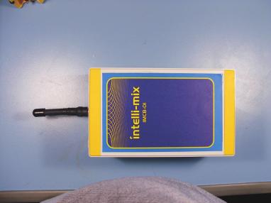
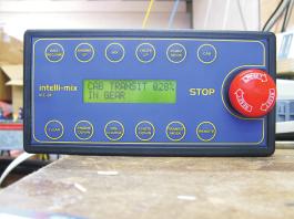
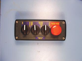
6 3. Introduction The Intelli-Mix IMCS is designed for the simple and safe control of concrete transport vehicles. The system controls the vehicle s engine speed, bowl speed and discharge chute, and can be operated from either a compact console in the vehicle cab, or from a remote control. A number of features are provided, including a Transit mode that allows the bowl to rotate at a constant rate irrespective of the engine speed, resulting in a more consistent mix, and reduced bowl wear. The Intelli-Mix IMCS system comprises five main components: In-Cab Console ICC-01: The in-cab console is typically located on the dashboard or above the operator s head in the vehicle cab. It provides full control of the machine, as well as an LCD display that informs the operator of the machine status. Radio Control Transmitter IMLK-08: The transmitter provides full control of the machine functions without the need for trailing cables, allowing the operator to choose the most convenient and safest location from which to monitor operations. Rear Command Station RCS-01: The control station located at the rear of the truck includes a STOP button that can be used to interrupt machine operations if necessary. As an option, the RCS-01 can be provided with additional controls for the engine speed and bowl speed - most commonly as an alternative to radio control. Control Board IMCB-01: The control board may be located in a less-accessible part of the vehicle, as it has no operator controls. The IMCB-01 contains the main control system, power supply, and drive electronics, as well as some diagnostic displays. 3
7 The LBC930D Battery Charger The IMLK-08 transmitter is supplied with 2 batteries that are placed in the LBC930D for recharging. 4

8 4. Display and Commands The Intelli-Mix IMCS system has a number of different controls and indicators. It is important that prior to using the system, the use of these controls, and the meaning of the indicators are known and understood by the operator Status Display on LCD The 2-line display on the ICC-01 in-cab controller displays the current machine status, and is segmented into a number of areas as described below. Note that the status displayed reflects the drive signals from the Intelli-mix to the vehicle in the event that there is a mechanical, electrical, or hydraulic fault, this may not necessarily reflect the actual machine state. Should the machine not operate as expected, press the STOP button, turn off the engine and consult the Trouble-shooting section. 5
9 Control Mode Indicates whether the ICC cab controller or the remote control panel is being used to control the system. (The remote control panel may be either the IMLK-08 radio controller or the RCS-01 control station, depending on which is fitted to the vehicle). As a safety measure, the machine can only be controlled from one location at any one time. CAB: Commands are being accepted from the ICC-01 in-cab controller. The remote control (either the IMLK-08 radio controller, or the RCS-01 cabled control station) is not functional. The STOP button of the RCS-01 is always operational, regardless of the control mode. RMT: Commands are being accepted from the IMLK-08 remote control, or RCS-01 control station (whichever is fitted). The in-cab controller is not functional, except for the CAB button which can be used to pass control back to the in-cab controller. The STOP button located on the ICC-01 is always operational, regardless of the control mode Bowl Mode Displays the current direction and speed of the bowl, as well as any special control mode being used. EMERGNY-STOP: One of the emergency-stop buttons is depressed, and there is no power to the bowl or chute. If the system is in Remote control mode, then the radio system may not be enabled press the Start button on the transmitter. The Stop buttons located on the ICC cab controller and elsewhere on the vehicle will stop the system in either Cab or Remote mode they must all be released before the bowl or chute can be used. BOWL STOPPED: There is no drive to the bowl hydraulics, so the bowl is stationary. 6
10 BOWL RUNNING: This is only displayed on systems which do not have an electronically-controlled bowl speed. On such systems, the bowl direction and speed are controlled by an electro-mechanical actuator, the position of which is not known to the IMCS. In this type of installation, the IMCS can only display whether the bowl is running or stopped, with no indication of direction or speed. STOPPING. : A command to stop the bowl has been accepted, and the bowl is ramping down in speed. The display will change to BOWL STOPPED when the drive to the hydraulics has been reduced to zero, which brings the bowl to rest. It is necessary to wait for the bowl to stop before further bowl commands will be accepted. MIX : The bowl is rotating in the mix direction. Also shown is the drive signal being given to the hydraulic system., displayed as a percentage. A higher value means a higher bowl speed, although this may also be affected by the engine speed. DISCHG: The bowl is rotating in the discharge direction. Also shown is the drive signal being given to the hydraulic system., displayed as a percentage. A higher value means a higher bowl speed, although this may also be affected by the engine speed. The ICC-01 will beep every 3 seconds while the bowl is in discharge mode. PLANT : The bowl is rotating in the mix direction, with a 100% drive to the hydraulic controls. This mode is typically used for initial loading of the mixer. TRANSIT : The bowl is rotating in the mix direction. Also displayed is the drive signal being given to the hydraulic system, displayed as a percentage. This value will automatically decrease as the engine speed rises, in order to keep the bowl speed approximately constant. Transit mode is only available on vehicles with electronic control of the hydraulic pump Engine Mode This displays the percentage of engine speed requested of the vehicle computer (also know as the Engine Control Unit or ECU). There are interlocks that must be present before the engine speed can be raised above idle the park brake must be 7
11 engaged, the footbrake must be off, and the transmission must be in Neutral (for vehicles that have a compatible transmission). Some installations will also require that the Remote Throttle switch (if fitted) is in the Remote position. Note: Some vehicle computers are configured to only recognise a change to remote throttle when the engine is not under load. On such vehicles, switching ON the remote throttle switch will automatically slow and stop the bowl. Once stopped, it may be restarted in the mode desired. ECU: The engine computer is requested to set the engine speed to a value indicated by the percentage shown. A higher value indicates a higher engine speed. PARKBRKE : No command is being given to the engine computer because the park brake is engaged. If a Remote Throttle switch is fitted to the vehicle, this must be in the Remote position. FOOTBRKE : No command is being given to the engine computer because the foot brake is depressed. IN GEAR : No command is being given to the engine computer because the transmission is not in neutral. Blank : On vehicles without a direct interface to the engine computer, the engine mode display will be blank once all interlocks have been satisfied Information Area This section of the display may contain different information, depending on how the system was configured: Blank: no additional information is available RPM: The current engine speed is displayed ERR: an internal error has occurred, and an error code is given. Record the error code, turn off the Intelli-mix system, and seek technical assistance. 8
12 nnn:xxx (where nnn and xxx are 3-digit numbers). This indicates that the system is in User Diagnostics mode, and is displaying information for troubleshooting purposes. For more information, see the section on User Diagnostics. To exit this mode, press the CLEAR button to stop the bowl, then press and release the STOP button Controls Backlight The display backlight is normally on whenever the system is powered. If automatic-dimming has been enabled, then the backlight will dim whenever the vehicle is in-gear or the park brake is released, to minimize driver distraction STOP mushroom button The red STOP button on the cab control unit latches down when pressed, and must be twisted gently clockwise to release it. Pressing the STOP button will return the engine to idle and stop all motion of the bowl and chute. These functions are not usable until the STOP button is released. This button should only be used in urgent circumstances, as it stops the bowl without first ramping down. To stop the bowl normally, use the CLEAR button, which will slow the bowl gradually to a stop Halt/Resume Button The Halt/Resume button allows the operator to temporarily halt the operation of the machine, then to later resume the same bowl direction, speed, and engine speed. If the bowl is in the MIX, DISCHARGE, PLANT or TRANSIT mode when the button is pressed, then the current settings are saved to memory, then the bowl is slowed to a stop and the engine returned to idle. When the button is pressed again, the bowl resumes the same mode and speed, and the engine returns to the original speed (only on vehicles with direct connection to the engine computer). As a safety measure, pressing any buttons other than Chute Up/Down after halting will prevent resumption. In that case, manually set the bowl and engine to the desired settings. 9
13 Clear Button The Clear button is used to ramp the bowl to a stop and bring the engine speed back to idle. It is not intended for use under urgent circumstances in that case, press the red STOP button Engine Up/Down Buttons When the Engine Up/Down button is depressed, the engine speed is increased/decreased within the programmed limits. Interlocks are present which will prevent the engine increasing above idle until the footbrake, park-brake, transmission and Remote-Throttle switch (if fitted) are in the correct states see the section on the Engine Mode display for more details. For vehicles with a direct interface to the engine computer, the status display will show the percentage of engine speed being requested Chute Up/Down Buttons Drives the chute up or down while the button is pressed. Ensure that the chute is not obstructed by persons or objects before commencing motion. The chute will move as long as the button is held depressed Mix Button Pressing the Mix button has slightly different results depending on the current control mode: Mix Mode: If the bowl is currently mixing, then pressing the Mix button will increase the bowl speed. Pressing the button momentarily will increase the speed by a small increment. If the button is pressed and held, the speed will 10
14 continue to increase until the button is released. Once the hydraulic drive signal reaches 100%, the bowl speed will not increase further further increase may be possible by raising the engine speed. Plant Mode: If the machine is in Plant Mode, the bowl is already rotating at full speed in the Mix Direction. Pressing the Mix button has no effect. Discharge Mode: If the bowl is currently discharging, then pressing the Mix button will decrease the bowl speed. Pressing the button momentarily will decrease the speed by a small increment. If the button is pressed and held, the speed will continue to decrease until the button is released. Once the hydraulic drive signal reaches 0%, the bowl will stop. If the Mix button is held down or pressed again, the direction will reverse, and the machine will enter Mix Mode, and the bowl speed will start to increase. Stopped: On vehicles with an electronically-controlled hydraulic pump, pressing the Mix button while the bowl is stopped will enter Mix mode, and set the bowl speed to minimum. Pressing or holding the Mix button will then behave as per Mix mode above. On vehicles with a mechanically-controlled pump, pressing the Mix button will enable the pump, and it will resume operation in the direction in which it was last operated, which may be in the discharge mode. For that reason, it is important on such vehicles to carefully monitor the bowl when starting. Holding the Mix button down while the bowl is discharging will slow it to a stop, then reverse it. Transit Mode: In transit mode, the system holds the bowl speed relatively constant by reducing the hydraulic drive as the engine speed increases. Pressing the Mix button while in Transit mode will increase the target bowl speed within the allowable limits Discharge Button Pressing this button has slightly different results depending on the current control mode: 11
15 Discharge Mode: If the bowl is currently discharging, then pressing the Discharge button will increase the bowl speed. Pressing the button momentarily will increase the speed by a small increment. If the button is pressed and held, the speed will continue to increase until the button is released. Once the hydraulic drive signal reaches 100%, the bowl speed will not increase further further increase may be possible by raising the engine speed. Plant Mode: If the machine is in Plant Mode, the bowl is rotating at full speed in the Mix Direction. Pressing the Discharge button will change the mode to Mix, and the bowl speed will start to decrease. Mix Mode: If the bowl is currently mixing, then pressing the Discharge button will decrease the bowl speed. Pressing the button momentarily will decrease the speed by a small increment. If the button is pressed and held, the speed will continue to decrease until the button is released. Once the hydraulic drive signal reaches 0%, the bowl will stop. If the Discharge button is held down or pressed again, the direction will reverse, and the machine will enter Discharge Mode, and the bowl speed will start to increase. Stopped: On vehicles with an electronically-controlled hydraulic pump, pressing the Discharge button while the bowl is stopped will enter Discharge mode, and set the bowl speed to minimum. Pressing or holding the Discharge button will then behave as per Discharge mode above. On vehicles with a mechanically-controlled pump, pressing the Discharge button will enable the pump, and it will resume operation in the direction in which it was last operated, which may be in the Mix mode. For that reason, it is important on such vehicles to carefully monitor the bowl when starting. Holding the Discharge button down while the bowl is mixing will slow it to a stop, then reverse it. Transit Mode: In transit mode, the system holds the bowl mixing speed relatively constant by reducing the hydraulic drive as the engine speed increases. Pressing the Discharge button while in Transit mode will decrease the target bowl speed within the allowable limits Plant Button The plant mode button drives the bowl to full mix speed and increases the engine speed to the preset plant speed (as long as the required interlocks are met). It is not possible to enter Plant Mode directly from Discharge mode stop the bowl first using 12
16 the CLEAR button, and wait until the bowl ramps down to a complete stop. Once in Plant Mode, the engine speed can be adjusted using the Engine Up/Down buttons. Pressing the Plant Mode button again will bring the engine speed back to the preset speed. On vehicles with a mechanically-controlled hydraulic pump, pressing the Plant button will activate the hydraulic pump in the direction in which it was last used, which may cause the bowl to initially rotate in the discharge direction. For that reason, the bowl on such systems must be carefully observed when starting. Once started, the bowl speed will be ramped to full speed in the Mix direction Transit Button (Note: On vehicles with no tachometer input to the IMCS, transit mode gives a fixed drive signal to the hydraulic system, and the bowl speed will fluctuate as the engine speed changes. On vehicles without electronic control of the hydraulic pump, transit mode is disabled.) The Transit button drives the bowl to a preset mix speed and removes the drive signal to the engine computer. For correct operation, the Remote Throttle switch (if fitted) must be in the Normal position. The drive to the hydraulic system will then be automatically increased or decreased in order to keep the bowl speed constant as the engine speed changes while driving. It is not possible to enter Transit Mode directly from Discharge mode stop the bowl first using the CLEAR button, and wait until the bowl ramps down to a complete stop. Once in Transit Mode, the target bowl speed can be adjusted using the Mix/Discharge buttons within the permitted limits. Pressing the Transit button again will return to the standard transit speed. (This is useful for temporarily increasing the transit speed while ascending a steep incline increase the transit speed using the Mix button, then return to the standard speed by pressing the Transit button again). To permanently change the default Transit speed, proceed as follows: - Enter Transit mode - Adjust the bowl speed as required using the Mix and Discharge buttons 13
17 - Press and hold the Transit button for 3 seconds to set this as the default Transit speed the cab unit will emit a long beep to indicate acceptance of the command. To return to Mix or Discharge Mode from Transit Mode, press the Clear button and wait for the bowl to stop before making another selection Cab Button Pressing this button puts the system into Cab control mode, and disables the remote control (IMLK-08 radio control or RCS-01 control station). It is the only button other than the STOP on the In-Cab controller that functions in Remote mode. If the system is running on the remote control when the Cab button is pressed, it will continue to run Remote Button Pressing this button puts the system into Remote control mode, and disables the in-cab console buttons (except for the STOP button, and the CAB button which can be used to return to Cab control). If the system is running on the cab controls when the Remote button is pressed, the bowl will stop and the engine will return to idle as a safety measure. The remote control must then be Started and used normally see the section on the IMLK-08 or RCS-01 for further details. 14

18 4.3. IMLK-08 remote control transmitter The controls available on the IMLK-08 transmitter are largely the same as those on the ICC-01 cab controller, although there are no Cab or Remote buttons to change between Cab-Remote modes, the cab controller must be used. Refer to the section on the ICC-01 for a description of the command buttons - the section below describes the special features of the IMLK-08: Starting When remote control mode is first selected, there will be no power to the controls, and the ICC will display EMERGENCY STOP. To enable the radio system, proceed as follows: - Ensure that there is a battery in the transmitter, and that the key-tag is inserted. - Ensure that the STOP button is released (twist it gently clockwise to release it). - Press and hold the start button for approximately 4 seconds or until the in-cab controller is heard to beep. - The green LED on the transmitter will flash about once per second to show it is operating - Control the system as you would using the cab controller Stopping Pressing the STOP button on the transmitter will cause immediate loss of power to the bowl and chute drive systems. While this is appropriate in urgent circumstances, it is unnecessary for normal use stop the bowl by pressing the Clear button, then press the STOP mushroom to turn the transmitter off. 15
19 Changing Frequency If the system performs stops unexpectedly while being controlled from the IMLK-08 remote control, there may have been a temporary loss of radio communication. Press the START button on the transmitter again to restart. If such interruptions continue, there may be interference on the radio link (such as from another remote control on an adjacent machine). To change the operating frequency, proceed as follows: - Start the IMLK-08 remote control normally - While pressing the START button, press the STOP button on the IMLK-08 remote control - While still holding the START button depressed, gently twist the STOP button to release it - Release the START button, then press and hold for 8-10 seconds to restart on the new frequency Low Battery Once the START button on the transmitter is pressed, the green LED on the transmitter will emit a quick flash at an interval of about one second to show that it is operational. Once started, the transmitter will continue to operate until it is turned off or the battery goes flat press the STOP button to turn the controller off, after first stopping the bowl with the CLEAR button. A fullycharged battery will operate the transmitter for approximately 12 hours. When there is less than 30 minutes of operation time remaining, the green LED on the transmitter will change to RED to indicate that a system STOP is imminent. The system should be stopped immediately using the CLEAR button, and the battery changed. 16

20 4.4. Rear Control Station RCS-01 The rear control station may be fitted with a STOP button only, or with additional engine, and bowl controls. The STOP button operates in both Cab and Remote modes, but the other controls are only operational when Remote operation has been selected. The functions of the various commands are the same as those on the ICC-01 cab controller refer to that section for details. 17

21 4.5. LBC930D Battery Charger When the remote control battery level is low, the green LED on the transmitter will change to red. Stop the bowl, then swap the battery with the one in the charger. The charger has two indicator lamps: Power: Illuminated Green whenever power is applied to the charger. Charge: Illuminated yellow whenever a battery is charging. When a battery is first inserted, the Charge LED may flash to indicate that the charger is conducting a test cycle. If the Charge lamp flashes for more than 4 hours, then the battery is faulty, and requires replacement. Note that batteries should only be charged when they are flat excessive charging will reduce the battery lifetime. Only charge the batteries in temperatures between 5 o C and 45 o C. Do not store batteries in very hot locations e.g. on the dashboard of a vehicle. 18
22 5. Troubleshooting Symptom: No display on ICC-01 controller Check: Power lamp on IMCB-01 IMCB Power Lamp On: Cable to IMCB-01 Contrast adjustment IMCB Power Lamp Off: Power supply to IMCB-01 Internal protection circuits remove power, wait 5 minutes, and retry. Symptom: ICC-01 displays COMMUNICATION ERROR Check: Cable to IMCB-01 ICC-01 displays EMERGENCY STOP Check: Machine STOP buttons If in REMOTE mode, start the IMLK-08 radio control Cannot raise Engine Speed above idle Check: Display on ICC-01 for which interlock is responsible (see Engine Mode on page 7) 19
23 5.1. User Diagnostics mode User Diagnostics mode is not a normal function of the control system. It is a special mode that allows normal control of the machine, but displays some internal parameters for diagnostic purposes. If requested to enter User Diagnostic mode by a technician trouble-shooting the system, proceed as follows: To enter User Diagnostics mode - Press the CAB button to ensure that the system is in CAB mode - Press the CLEAR button and wait for the bowl to stop - Press and hold the CAB button - With the CAB button held down, press the STOP button in - With the CAB button still held down, release the STOP button - Release the CAB button Functions in User Diagnostics Mode In User Diagnostics mode, the Information Area on the ICC-01 screen shows a value nnn:xxx where: nnn is the number of the parameter being displayed xxx is the value of the parameter being displayed 20
24 Pressing the CAB button will scroll through the various parameters one-by-one. If you are performing diagnostics under instruction from a technician, they will tell you which parameter to scroll to, and they will interpret the data there. A full description of the various parameters and their meanings may be found in the Intellimix IMCS Technical Manual. While User Diagnostics mode is active, it is also possible to set the engine speed minimum and maximum values requested of the ECU. Because the normal restrictions on engine speed do not apply, extra caution should be exercised when setting the speed this way. To set the minimum (idle) speed requested of the ECU - Enter User Diagnostics Mode as described above - Press the CAB button to ensure that the system is in CAB mode - Press the CLEAR button and wait for the bowl to stop - Ensure the park brake is on, the foot brake is off, and the transmission is in neutral - Ensure the Remote Throttle switch (if fitted) is in the Remote position - Press the ENGINE DOWN button until the engine speed drops to idle - Press the ENGINE UP button until the engine speed increases slightly above idle - Press the ENGINE DOWN button until the engine speed just drops to idle - With the CAB button held down, press the ENGINE DOWN button to set the minimum speed To set the maximum speed requested of the ECU - Enter User Diagnostics Mode as described above - Press the CAB button to ensure that the system is in CAB mode - Press the CLEAR button and wait for the bowl to stop - Ensure the park brake is on, the foot brake is off, and the transmission is in neutral - Ensure the Remote Throttle switch (if fitted) is in the Remote position 21
25 - Adjust the engine speed using the ENGINE UP / ENGINE DOWN buttons until the desired maximum speed is reached. - With the CAB button held down, press the ENGINE UP button to set the maximum speed After setting the engine speeds, exit User Diagnostics mode, and test the minimum and maximum speeds are operating as expected To exit User diagnostics mode - Press the CAB button to ensure that the system is in CAB mode - Press the CLEAR button and wait for the bowl to stop - Press the STOP button - Release the STOP button and operate the system normally 22
26 6. Maintenance 6.1. Every Day Before operating the system, check the operation of all commands. In particular, start the bowl spinning slowly and press the STOP button to ensure that the bowl stops immediately Annually The system should be inspected annually by a technician competent to do so. Refer to the Intelli-mix IMCS Technical Manual for a description of the recommended tests Cleaning Do not use any solvents or abrasives to clean the components of the system. A moist cloth may be used to clean the external surfaces of the ICC-01, RCS-01, IMLK-08, and IMCB-01. Use a dry cloth when cleaning the LBC930D charger. 23
27 6.4. Storage Store the system in a clean dry location with a temperature between 5oC and 35oC. If the system is unused for 30 days or more, the batteries must be removed from the IMLK-08 transmitter, and charged. The charge should be repeated every 60 days Disposal The components of the IMCS control system contain substances which may be subject to disposal restrictions in some jurisdictions the circuit boards contain lead in the solder, and the NiMH batteries may require special handling. Consult your local authority or your supplier for further instructions. 24

28
EAGLETRON II REMOTE CONTROL OPERATOR and MAINTENANCE. Remote Control Procedure
 EAGLETRON II REMOTE CONTROL OPERATOR and MAINTENANCE Remote Control Procedure WARNING! DO NOT OPERATE REMOTE CONTROL UNLESS YOU HAVE A CLEAR VIEW OF THE REAR OF THE TRAILER. WARNING! THE OPERATOR IS REQUIRED
Fuller Automated Transmissions TRDR2500
 Driver Instructions Fuller Automated Transmissions TRDR2500 July 2007 RTO-10910B-DM2 RTO-12910B-DM2 RTO-14910B-DM2 RTO-16910B-DM2 Warnings & Cautions Warnings & Cautions WARNING Read the entire driver
Commander 15i Container and Pallet Loader. Property of American Airlines
 Commander 15i Container and Pallet Loader Section 2. Operation BEFORE ATTEMPTING TO OPERATE OR MAINTAIN THE VEHICLE, COMPLETELY READ AND UNDERSTAND THE OPERATION AND MAINTENANCE MANUAL, INCLUDING ALL DANGER,,
B-RAD Select USER MANUAL TABLE OF CONTENTS
 TABLE OF CONTENTS TABLE OF CONTENTS... 1 MANUAL REVISION HISTORY... 2 IMPORTANT SAFETY NOTICE... 3 1.0 General Information... 5 1.1 System Components... 5 1.2 Specifications... 5 1.2.1 Torque Ranges...
30A BLDC ESC. Figure 1: 30A BLDC ESC
 30A BLDC ESC Figure 1: 30A BLDC ESC Introduction This is fully programmable 30A BLDC ESC with 5V, 3A BEC. Can drive motors with continuous 30Amp load current. It has sturdy construction with 2 separate
CONTROLLER DIAGNOSTIC GUIDE
 Proprietary tice: This document contains proprietary information which not to be reproduced, transferred, to other documents, disclosed to others, used for manufacturing or any other purpose without the
Fuller Automated Transmissions TRDR0082
 Driver Instructions Video Instruction Available Instructional videos are available for download at no charge at roadranger.com Videos are also available for purchase. To order, call 1-888-386-4636. Ask
SECTION 2 - PROCEDURES. Features. 2.6 MOTOR CONTROLLER. Modes of Operation JLG Lift 2-5
 2.6 MOTOR CONTROLLER. Modes of Operation. 1. Traction Motor Drive. a. Drive in either forward or reverse will start only if the following conditions are satisfied: 1. Function switches off. 2. No procedure
Operators Guide: RoboSign Stop/Go Traffic Control System
 Operators Guide: RoboSign Stop/Go Traffic Control System RoboSign Remote controlled Stop/Go temporary traffic control system Operators Guide NZTA Conditions - Automated Stop/Go Traffic Control System NZTA
NEW HOLLAND TM120 TM130 TM140 TM155 TM175 TM190 SUPPLEMENT TO OPERATORS MANUAL
 NEW HOLLAND TM120 TM130 TM140 TM155 TM175 TM190 SUPPLEMENT TO OPERATORS MANUAL 604.53.401.00 (82998307) 604.53.401.10 (82998410) blank Series TM Operator s Manual Supplement INTRODUCTION This Supplement
Operators Guide: RoboSign Stop/Go Traffic Control System
 Operators Guide: RoboSign Stop/Go Traffic Control System RoboSign Remote controlled Stop/Go temporary traffic control system Operators Guide Table of Contents Operators Guide: RoboSign Stop/Go Traffic
PRESSURE GOVERNOR, ENGINE MONITORING, AND MASTER PRESSURE DISPLAY MODEL: TCA100
 Document Number: XE-TCA1PM-R0A TCA100 Rev0511 PRESSURE GOVERNOR, ENGINE MONITORING, AND MASTER PRESSURE DISPLAY MODEL: TCA100 FIRE RESEARCH CORPORATION www.fireresearch.com 26 Southern Blvd., Nesconset,
Intelli-Feed Controller User s Manual Intelli-Feed Digital Tachometer and Hourmeter
 Intelli-Feed Controller User s Manual Intelli-Feed Digital Tachometer and Hourmeter Part #: 9047 Table of Contents: Table of Contents 2 Intelli-Feed TM User Interface 3 Equipment Diagnostic Indicators
RD712 & RD712XL Remote Displays. Model 615 / 615XL Indicator User s Manual
 RD712 & RD712XL Remote Displays Model 615 / 615XL Indicator User s Manual EUROPEAN COUNTRIES WARNING This is a Class A product. In a domestic environment this product may cause radio interference in which
SAC SERIES CONTENTS TRIPLE-INTERVAL HIGH PRECISION COUNTING SCALE OPERATION MANUAL 1. INSTALLATION 2. SPECIFICATIONS
 CONTENTS SAC SERIES TRIPLE-INTERVAL HIGH PRECISION COUNTING SCALE 1. INSTALLATION 2. SPECIFICATIONS 2.1 GENERAL SPECIFICATIONS 2.2 MINIMUM PIECES, WEIGHT APPLIED & SAMPLE SIZE WEIGHT SPECIFICATIONS OPERATION
CeraControl. Temperature Programmer User Handbook.
 CeraControl Temperature Programmer User Handbook www.potterycrafts.co.uk See separate handbook for Installation Instructions Issue: 1.01 CeraControl Copyright User 2014 Handbook Potterycrafts Ltd. Date:
V8 Vantage Sportshift Driving Guide
 LG/GE/10/03/2011 The V8 Vantage incorporates a 6-speed Sportshift automated manual transmission. There are two driving modes for V8 Vantage Sportshift. The first is Paddle Shift Mode This is the mode where
Aftermarket Interface Module
 An ISO 9001:2008 Registered Company Aftermarket Interface Module (2015-2018 Ford Transit) AIM514-B High Side Solenoid type Coolant Valve Control AIM515-B Motor Reversing type Coolant Valve Control Introduction
Power Sliding Door (PSD) Diagnostic Approach. Fixing Intermittent Malfunctions. Power Sliding Door (PSD) Diagnostic Information
 Diagnostic Approach. Fixing Intermittent Malfunctions. Power Sliding Door (PSD) Diagnostic Information") Power Sliding Door (PSD) Diagnostic Information Power Sliding Door (PSD) The power sliding door (PSD) provides built-in diagnostics. This assists the service technicians during troubleshooting. The PSD
Power Sliding Door (PSD) Diagnostic Information Power Sliding Door (PSD) The power sliding door (PSD) provides built-in diagnostics. This assists the service technicians during troubleshooting. The PSD
2001 Chevrolet Corvette ACCESSORIES & EQUIPMENT Remote Keyless Entry Systems - Corvette
 DESCRIPTION 2001 ACCESSORIES & EQUIPMENT Remote Keyless Entry Systems - Corvette Remote Keyless Entry (RKE) system is controlled by Remote Function Actuation (RFA) system. Transmitter allows remote control
DIGITAL BATTERY TORQUE WRENCH (BC-RAD SELECT) USER GUIDE
 USER GUIDE") DIGITAL BATTERY TORQUE WRENCH (BC-RAD SELECT) USER GUIDE W.CHRISTIE (INDUSTRIAL) LTD CHRISTIE HOUSE, MEADOWBANK ROAD, ROTHERHAM, SOUTH YORKSHIRE, S61 2NF, UK T: +44(0)1709 550088 F: +44(0)1709 550030 E:
DIGITAL BATTERY TORQUE WRENCH (BC-RAD SELECT) USER GUIDE W.CHRISTIE (INDUSTRIAL) LTD CHRISTIE HOUSE, MEADOWBANK ROAD, ROTHERHAM, SOUTH YORKSHIRE, S61 2NF, UK T: +44(0)1709 550088 F: +44(0)1709 550030 E:
Reference Guide and Step-by-Step Installation Manual
 Reference Guide and Step-by-Step Installation Manual Some adjustable features listed on the following pages are NOT applicable for all applications. The year, make, and model of the vehicle will determine
SmarTire TPMS Maintenance Hand Tool. Revision User Manual
 SmarTire TPMS Maintenance Hand Tool Revision 1.04 User Manual Page 2 Table of Contents FCC Compliance Label... 4 User Interface Illustration... 4 Introduction... 5 Testing Tire Sensors... 5 Main Menu...
Versaguard MAX Console OEM Guide
 Versaguard MAX Console OEM Guide TABLE OF CONTENTS SECTION PAGE 1 FUNCTION OVERVIEW 1.1 LCD INFMATION CENTER... 1 1.2 LCD QUICK BUTTONS... 2 1.3 LED INDICATS... 2 1.4 ELECTRONIC PARKING BRAKE... 2 1.5
SCHEMATIC AND ROUTING DIAGRAMS
 2004 ACCESSORIES & EQUIPMENT Keyless Entry - Corvette SCHEMATIC AND ROUTING DIAGRAMS KEYLESS ENTRY SCHEMATICS Fig. 1: Driver Door Schematic Courtesy of GENERAL MOTORS CORP. Fig. 2: Passenger Door Schematic
S D ST215 TAFFOR. ST215 Temperature Programmer User Handbook.
 TAFFOR S D ST215 ST215 Temperature Programmer User Handbook www.staffordinstruments.co.uk See separate handbook for Installation Instructions Issue: 1.000 ST215 Copyright User Handbook 2014 Stafford Instruments
Solar Hybrid Power Generating System CPS1200EOH12SC CPS2200EOH24SC CPS3000EOH24SC. User s Manual K01-C
 Solar Hybrid Power Generating System CPS1200EOH12SC CPS2200EOH24SC CPS3000EOH24SC User s Manual K01-C000304-02 2 TABLE OF CONTENTS 1 IMPORTANT SAFETY INSTRUCTIONS..4 2 INSTALLATION....5 2-1 Unpacking...5
Transmission AUTOMATIC TRANSMISSION. Gearshift interlock
 Transmission AUTOMATIC TRANSMISSION WARNING Park (P) should be engaged when the vehicle is stationary. The vehicle can move unexpectedly with any other gear position selected, which may result in death
Subject Underhood G System Error Codes and Symptoms System or Parts affected
 System or Parts affected Index Underhood70G (V90Gxxx) System or Parts affected... 1 Overview... 1 Identifying your System... 1 Retrieving Logged Error Messages... 1 Error Messages... 3 Error Message Table...
BATTERY CHARGER RS-1000 Instruction Manual
 BATTERY CHARGER RS-1000 Instruction Manual BEFORE USING OUR BATTERY CHARGER RS1000, READ IN DETAILS ALL INSTRUCTIONS CONTAINED IN THIS MANUAL. KEEP THIS MANUAL IN A SAFE PLACE AS YOU MAY NEED TO USE IT
MaxxForce 11 and 13 (2010)
") MaxxForce 11 and 13 (2010) Overview: In Cab Control NAV_PTOIC_070511 In-Cab Control TABLE OF CONTENTS General Overview: In-Cab Control... 1 Description and Operation... 1 OPERATION...1 STATIONARY VARIABLE...1
MaxxForce 11 and 13 (2010) Overview: In Cab Control NAV_PTOIC_070511 In-Cab Control TABLE OF CONTENTS General Overview: In-Cab Control... 1 Description and Operation... 1 OPERATION...1 STATIONARY VARIABLE...1
PRESSURE GOVERNOR, ENGINE MONITORING, AND MASTER PRESSURE DISPLAY MODEL DDA100
 PRESSURE GOVERNOR, ENGINE MONITORING, AND MASTER PRESSURE DISPLAY MODEL DDA100 1 CONTENTS Table of Contents CONTENTS... 2 INTRODUCTION... 4 Overview... 4 Features... 4 GENERAL DESCRIPTION... 5 2 List of
PowerLevel s e r i e s
 Owner s Manual Hydraulic Leveling CONTENTS Introduction Operation Control Panel Automatic Leveling Manual Leveling Retracting Jacks Remote Operation Care & Maintenance Troubleshooting Error Codes 1 2 2
PRESSURE GOVERNOR, ENGINE MONITORING, AND MASTER PRESSURE DISPLAY MODEL TCA200
 Document Number: XE-TCA2PM-R0A TCA200 Rev171031 PRESSURE GOVERNOR, ENGINE MONITORING, AND MASTER PRESSURE DISPLAY MODEL TCA200 FIRE RESEARCH CORPORATION www.fireresearch.com 26 Southern Blvd., Nesconset,
OPERATING INSTRUCTIONS
 DS7 2-WAY REMOTE START SYSTEM OPERATING INSTRUCTIONS CONGRATULATIONS on your choice of a Data Start Remote Engine Starter and Keyless Entry by Crimestopper Security Products Inc. This system is designed
Installation and User Manual. with RAIN SENSOR.
 with RAIN SENSOR www.solarsmartopener.com Revision..0 TABLE OF CONTENTS Features In The Box Further Items Required Basic Operation Solar Panel and Operator Installation Operator Installation Solar Panel
RS-230-DP. Operation Guide
 RS-230-DP Deluxe Keyless Entry & Remote Start July 27, 2010 Operation Guide Temporary cover. Color cover is in a separate file. Table Of Contents Introduction...2 The Transmitter...3 Transmitter Functions...3
Subject: Power Take Off (PTO) Models Affected: ADVISORY:
 Models Affected: ADVISORY:") Subject: Power Take Off (PTO) Subsystem Operating Description and Application Guide Models Affected: All New C/K 3500HD CC Chevrolet Silverado / GMC Sierra. Models C/K 36003, 36403 & 36043 Model Years:
Subject: Power Take Off (PTO) Subsystem Operating Description and Application Guide Models Affected: All New C/K 3500HD CC Chevrolet Silverado / GMC Sierra. Models C/K 36003, 36403 & 36043 Model Years:
SECTION 1 2 FEATURES ON NEW TOYOTA RAV4 EV. How to drive
 FEATURES ON NEW TOYOTA RAV4 EV How to drive SECTION 1 2 Before starting the traction motor.............................. 14 Motor switch with steering lock................................ 14 How to start
User manual. Minivator Limited 82 First Avenue Pensnett Estate Kingswinford West Midlands DY6 7FJ England
 Minivator Limited 82 First Avenue Pensnett Estate Kingswinford West Midlands DY FJ England Tel: + (0)38 0800 Fax: + (0)38 089 Email: sales@minivator.co.uk www.minivator.co.uk User manual Features of your
GENERAL INFORMATION. H-1649, H-1650, H-1651 H-1653, H-1654 Easy-Count. uline.com. that may hurt accuracy:
 π H-1649, H-1650, H-1651 H-1653, H-1654 Easy-Count counting scale 1-800-295-5510 uline.com 1-800-295-5510 GENERAL INFORMATION Avoid placing the scale in locations that may hurt accuracy: 1. Temperature
GLM SERIES CONTROL Users Manual Rev:
 GLM SERIES CONTROL Users Manual Rev: 808062 Connecting Power Page 2 Motor Terminal Wiring Diagrams Page 3 Getting Started / Setup Page 4 1. Obstruction Detection Devices Page 4 2. Checking Power and Direction
INSTALLING THE #OMEGA-3v9s ESC.
 - 2 - INSTALLING THE #OMEGA-3v9s ESC. We usually supply the # OMEGA-3v9s ESC with a Lemon brand Rx which is simply plugged in upside down on the ESC pcb in the 24 pin socket. The two parts are bench tested
RCLS Operation -CANAC
 Canadian Pacific Railway Job Aids/Special Instructions CANAC REMOTE CONTROL LOCOMOTIVE SYSTEM RCLS Operation -CANAC Special Instructions for the use of Canac Remote Control Locomotive System (RCLS) 1.0
OPERATING INSTRUCTIONS
 LCPRO-3 and LCPRO-4 LOW CURRENT REMOTE START SYSTEM OPERATING INSTRUCTIONS CONGRATULATIONS on your choice of a PRO Start Remote Engine Starter and Keyless Entry by Crimestopper Security Products Inc. This
USER MANUAL. Power GUARD UPS. Uninterruptible Power System
 USER MANUAL Power GUARD UPS Uninterruptible Power System IMPORTANT SAFETY INSTRUCTIONS SAVE THESE INSTRUCTIONS This manual contains important instructions for Power GUARD that should be followed during
TABLE OF CONTENTS. B-RAD Select USER MANUAL
 TABLE OF CONTENTS Manual Revision History... 2 General Power Tool Safety Warnings... 3 Battery Pack Safety Warnings... 5 1.0 General Information... 6 1.1 System Components... 6 1.2 Specifications... 6
Centrifuge Operator / Service Manual
 3000 Centrifuge Centrifuge Operator / Service Manual cat.# 26230 & 26231 The Q-sep 3000 centrifuge complies with all requirements of UL standard 3101 20, Can/CSA C22.2 No. 1010.1, and Can/CSA C22.2 No.
BATTERY CHARGER Instruction Manual
 BATTERY CHARGER Instruction Manual BEFORE USING OUR BATTERY CHARGER, READ IN DETAILS ALL INSTRUCTIONS CONTAINED IN THIS MANUAL. KEEP THIS MANUAL IN A SAFE PLACE AS YOU MAY NEED TO USE IT AT A LATER DATE.
NGW & HGW SERIES CONTENTS OPERATION MANUAL CAUTIONS HIGH RESOLUTION MULTI-FUNCTION DIGITAL SCALE 1. INSTALLATION 2. SPECIFICATIONS
 NGW & HGW SERIES HIGH RESOLUTION MULTI-FUNCTION DIGITAL SCALE CONTENTS CAUTIONS 1. INSTALLATION 2. SPECIFICATIONS OPERATION MANUAL 3. KEYBOARD LAYOUT AND DESCRIPTION 4. INITIAL SETUP PLEASE READ THIS MANUAL
RADIO CONTROLLED QUAD-COPTER WITH CAMERA
 Movie - DRONE TM RADIO CONTROLLED QUAD-COPTER WITH CAMERA FEATURING: 1. Four-Rotor design allows great speed and maneuverability for both Indoor and Outdoor use. 2. Built-in 6-axis Gyro ensures excellent
International A26 (2017)
") International A26 (2017) Overview: Control - In Cab A26_ICESC_12292017 In-Cab Control TABLE OF CONTENTS General Overview: In-Cab Control... 1 Description and Operation... 1 OPERATION...1 STATIONARY VARIABLE...1
International A26 (2017) Overview: Control - In Cab A26_ICESC_12292017 In-Cab Control TABLE OF CONTENTS General Overview: In-Cab Control... 1 Description and Operation... 1 OPERATION...1 STATIONARY VARIABLE...1
Operation and Maintenance Manual REMOTE DRIVE
 Operation and Maintenance Manual REMOTE DRIVE April 2015 SERIAL NUMBER NOTE: Please refer to the serial numbers when ordering parts or inquiring about warranty items. DMF 665 Pylant Street Atlanta, Georgia
16 37 TM INTEGRATED RADIO CONTROL INSTRUCTION MANUAL
 16-37 TM IRC Instruction Manual (99903542) 16 37 TM INTEGRATED RADIO CONTROL INSTRUCTION MANUAL 01.01 2007 IOWA MOLD TOOLING CO., INC. GARNER, IA 50438 1. Introduction... 2 2. The Components of the IRC-System...
XC Instrumentation System Owner s Manual Revision /05/06
 XC Instrumentation System Owner s Manual Revision 3.0 07/05/06 XC INSTRUMENTATION SYSTEM OWNER S MANUAL 1 Revision History Date New Revision Level Revision Description 11/08/05 1.0 Initial release 05/24/06
POWER TILT ACCESSORY FUZE T50 STELLAR GL STELLAR LEAP OWNER S OPERATION AND MAINTENANCE MANUAL
 POWER TILT ACCESSORY FUZE T50 STELLAR GL STELLAR LEAP OWNER S OPERATION AND MAINTENANCE MANUAL PAGE 2 WARNING Do not install, maintain or operate this equipment without first reading and understanding
OPERATING INSTRUCTIONS
 LCPRO-7 2-WAY REMOTE START SYSTEM OPERATING INSTRUCTIONS CONGRATULATIONS on your choice of a PRO Start Remote Engine Starter and Keyless Entry by Crimestopper Security Products Inc. This system is designed
BATTERY CHARGER Instruction Manual
 BATTERY CHARGER Instruction Manual BEFORE USING OUR BATTERY CHARGER, READ IN DETAILS ALL INSTRUCTIONS CONTAINED IN THIS MANUAL. KEEP THIS MANUAL IN A SAFE PLACE AS YOU MAY NEED TO USE IT LATER. We draw
Eaton VORAD Always Alert/SmartCruise/BlindSpotter. More time on the road. Driver Instructions
 Eaton VORAD Always Alert/SmartCruise/BlindSpotter More time on the road Driver Instructions Eaton VORAD Always Alert/SmartCruise/BlindSpotter VODR0035 October 2007 Warnings and Cautions Warnings and Cautions
OMEGA-3v7 Electronic Speed Controller
 P.O Box 578 Casino, NSW, 2470 Australia Phone: International ++614 2902 9083 Australia (04) 2902 9083 Website: http://rcs-rc.com E mail: Info@rcs-rc.com OMEGA-3v7 Electronic Speed Controller FULL INSTRUCTION
OPERATING INSTRUCTIONS
 EZ-1 ONE BUTTON REMOTE START SYSTEM OPERATING INSTRUCTIONS CONGRATULATIONS on your choice of a Cool Start Remote Engine Starter and Keyless Entry with DP Technology by Crimestopper Security Products Inc.
Galileo with wifi RADIO CONTROLLED QUAD-COPTER
 Galileo with wifi TM RADIO CONTROLLED QUAD-COPTER FEATURING: 1. Four-Rotor design allows great speed and maneuverability for both Indoor and Outdoor use. 2. Built-in 6-axis Gyro ensures excellent stability.
Riding Your Halo Go Before You Begin Safety Alerts
 HALO GOTM Before You Begin---------------------01 Riding Your Halo Go-----------07-10 Main Components-------------------02 Safety Alerts--------------------------11 Charging Your Batteries------------03
DATE: 7/29/99. PAGE: 1 of 32
 UI BULLETIN # 24 SUBJECT: Engine Speed Control for 7.4L (LP4/L21) Gas Engines MODELS AFFECTED: C-Series Trucks MODEL YEAR(S): 1999/2000 DATE: 7/29/99 PAGE: 1 of 32 The purpose of this bulletin is to provide
SECTION 1 7 OPERATION OF INSTRUMENTS AND CONTROLS Ignition switch, Transmission and Parking brake
 SECTION 1 7 OPERATION OF INSTRUMENTS AND CONTROLS Ignition switch, Transmission and Parking brake Ignition switch.............................................. 114 Automatic transmission.....................................
SECEUROGLIDE ROLLER GARAGE DOORS, SECEUROSHIELD, SECEUROSCREEN & SECEUROVISION ROLLER SHUTTERS CONTENTS
 Operating & Maintenance Instructions SECEUROGLIDE ROLLER GARAGE DOORS, July 2007 Issue 4 SECEUROSHIELD, SECEUROSCREEN & SECEUROVISION ROLLER SHUTTERS CONTENTS Page 1. General Instructions 2 2. Operating
Galileo RADIO CONTROLLED QUAD-COPTER
 Galileo TM RADIO CONTROLLED QUAD-COPTER FEATURING: 1. Four-Rotor design allows great speed and maneuverability for both Indoor and Outdoor use. 2. Built-in 6-axis Gyro ensures excellent stability. 3. Modular
EMIU 720W Mini Inverter
 THIS UNIT CONTAINS A RECHARGEABLE VALVE-REGULATED LEAD ACID BATTERY. PLEASE RECYCLE OR DISPOSE OF PROPERLY. INTERRUPTIBLE EMERGENCY LIGHTING UNIT INVERTER INSTRUCTION MANUAL IMPORTANT SAFEGUARDS When using
SAFETY PRECAUTIONS SAFETY FIRST!... 1 ABOUT THE CODE READER CONTROLS AND INDICATORS... 3 DISPLAY FUNCTIONS... 4
 Table of Contents SAFETY PRECAUTIONS SAFETY FIRST!... 1 ABOUT THE CODE READER CONTROLS AND INDICATORS... 3 DISPLAY FUNCTIONS... 4 USING THE CODE READER CODE RETRIEVAL PROCEDURE... 7 VIEWING ABS DTCs...
HC Model Railroad Handheld Controller
 HC Model Railroad Handheld Controller User Manual Ring Engineering Inc. (219) 322-0279 www.ringengineering.com Revision 2.00 Copyright 2017 Ring Engineering Inc. All rights reserved. Introduction...3 Warnings...3
OnGuard Display Operating Instructions
 Issued 09-09 Technical Bulletin Issued 1 Technical 09-09 Bulletin OnGuard Display Operating Instructions Hazard Alert Messages Read and observe all Warning and Caution hazard alert messages in this publication.
ESCONDIDO FIRE DEPT TRAINING MANUAL Section DRIVER OPERATOR Page 1 of 13 Pumps and Accessory Equipment Revised
 DRIVER OPERATOR Page 1 of 13 PUMPS AND ACCESSORY EQUIPMENT Pumps are designed for many different purposes. In order to understand the proper application and operation of a pump in a given situation, firefighters
SmarTire TPMS Maintenance Hand Tool. Revision User Manual
 SmarTire TPMS Maintenance Hand Tool Revision 1.03 User Manual Page 2 Table of Contents FCC Compliance Label...4 User Interface Illustration...4 Introduction...5 Testing Tire Sensors...5 Main Menu...6 Main
Terex Utilities. Issue: Action:
 Terex Utilities PRODUCT ADVISORY PA-1024-14 DATE: 7/21/14 REVISED: TO: Owners, Users, Dealers, and Installers Models Affected: Units with a 408V HyPower TM System Installed SUBJECT: 408V HyPower TM Systems
IMPORTANT SAFEGUARDS READ THIS MANUAL AND FOLLOW ALL SAFETY INSTRUCTIONS THOROUGHLY BEFORE OPERATING THE EMIU INVERTER SYSTEM SAVE THESE INSTRUCTIONS
 THIS UNIT CONTAINS A RECHARGEABLE VALVE-REGULATED LEAD ACID BATTERY. PLEASE RECYCLE OR DISPOSE OF PROPERLY. IMPORTANT SAFEGUARDS INTERRUPTIBLE EMERGENCY LIGHTING UNIT INVERTER INSTRUCTION MANUAL When using
Section 4.2. Machine Operation - Operator s Machine Controls. Engine Throttle Control Hydraulic Motor Shift Switch (630)
") Section 4.2 Machine Operation - Operator s Machine Controls Engine Throttle Control... 4.2.2 System Arm Switch... 4.2.2 Charge Heater Switch... 4.2.3 Parking Brake Switch... 4.2.3 Max Throttle Switch...
Section 4.2 Machine Operation - Operator s Machine Controls Engine Throttle Control... 4.2.2 System Arm Switch... 4.2.2 Charge Heater Switch... 4.2.3 Parking Brake Switch... 4.2.3 Max Throttle Switch...
CRUISE CONTROL SPEED LIMITER Rev. 4.0
 INSTALLATION f MANUAL CRUISE CONTROL & SPEED LIMITER AP900Series SL900Series 231.0004530 Rev. 4.0 1 2 CONTENTS: Chapters 1 Kit contents. 3 2 Tools required 4 3 Electronics module location... 5 4 Input
CRUISE CONTROL SYSTEM
 CRUISE CONTROL SYSTEM 1994 Toyota Celica 1994 ACCESSORIES & EQUIPMENT Toyota Motor Sales, U.S.A., Inc. - Cruise Control Systems Celica DESCRIPTION Cruise control system consists of Cruise Control Electronic
An ISO 9001:2008 Registered Company
 An ISO 9001:2008 Registered Company CVC501-A HVAC & Fast Idle CAN Vehicle Controller CVC502-A HVAC Control without Fast Idle 2011-2016 Ford F250-F550 (CVC501/502-A) 2017 Ford F-250-F550 (B-CVC501/502-A)
L I M I T E D L I F E T I M E W A R R A N T Y
 L I M I T E D L I F E T I M E W A R R A N T Y Products manufactured and sold by OMEGA RESEARCH & DEVELOPMENT, INC. (the Company), are warranted to be free from defects in materials and workmanship under
TIMER INTERFACE USER MANUAL
 TIMER INTERFACE USER MANUAL Premium Efficiency Two-Speed Motor with Integrated Timer Formerly A. O. Smith Electrical Products Company A Regal Beloit Company COPYRIGHT Copyright 2011, Regal Beloit EPC,
USER MANUAL BRUSHLESS SPEED CONTROLLER S5-RTR ESC S5A-RTR ESC RC CARS & TRUCKS
 USER MANUAL BRUSHLESS SPEED CONTROLLER S5-RTR ESC S5A-RTR ESC RC CARS & TRUCKS Declaration Thanks for purchasing our Electronic Speed Controller (ESC). High power system for RC model can be very dangerous,
IMPORTANT SAFEGUARDS READ THIS MANUAL AND FOLLOW ALL SAFETY INSTRUCTIONS THOROUGHLY BEFORE OPERATING THE LMIU INVERTER SYSTEM SAVE THESE INSTRUCTIONS
 THIS UNIT CONTAINS A RECHARGEABLE VALVE-REGULATED LEAD ACID BATTERY. PLEASE RECYCLE OR DISPOSE OF PROPERLY. IMPORTANT SAFEGUARDS INTERRUPTIBLE EMERGENCY LIGHTING UNIT INVERTER INSTRUCTION MANUAL When using
Features: Enhanced throttle response, excellent acceleration, linearity and driveability
 120A/150A ESC X-Car 120A/150A Series Sensored/Sensorless Brushless ESC for 1:8 scale Car or Truck Thank you for purchasing the X-Car Brushless Electronic Speed Controller (ESC). The X-Car 1:8 Scale 120A/150A
Please check our application list to see if we have a specific Harness Kit available for your motorcycle.
 GIpro X-type Install Guide for GPX-WSS Harness Kit Compatibility: This universal harness kit includes a Wheel Speed Sensor and will fit all motorcycles and vehicles which have electronic ignition system.
home ELITE CURVE CUSTOM CURVED RAIL STAIRLIFT Operator s Manual Keep this manual in a safe and readily accessible place for future reference.
 home ELITE CURVE CUSTOM CURVED RAIL STAIRLIFT Operator s Manual Keep this manual in a safe and readily accessible place for future reference. REV. 23 January 2015 PRODUCT REGISTRATION FORM home Product
MicroGuard 586. Operation/Setup Manual MG-586. Crane Systems. Rated Capacity Indicator/Limiter System GREER COMPANY. Page 1 of 44
 GREER COMPANY Crane Systems MicroGuard 586 Rated Capacity Indicator/Limiter System CODE Operation/Setup Manual Page 1 of 44 MicroGuard 586 Rated Capacity Indicator/Limiter System Operation/Setup Manual
User Manual. T6 Tachometer. Online: Telephone: P.O. Box St. Petersburg, Florida 33736
 User Manual T6 Tachometer Online: www.phareselectronics.com Telephone: 727-623-0894 P.O. Box 67251 St. Petersburg, Florida 33736 Table of Contents Overview... 1 Description... 1 Wiring... 1 T6 Tachometer
Automated Control Electronics (ACE ) System Operation and Diagnostics
 System Operation and Diagnostics") Commercial Products Automated Control Electronics (ACE ) System Operation and Diagnostics PART NO. 98962SL This page is intentionally blank. Table of Contents Introduction... 1 Controller Operation and
Commercial Products Automated Control Electronics (ACE ) System Operation and Diagnostics PART NO. 98962SL This page is intentionally blank. Table of Contents Introduction... 1 Controller Operation and
ST315B. User Handbook STAFFOR. ST315B Temperature Programmer. See separate handbook for Installation Instructions Issue: 2.00
 STAFFOR D ST315B User Handbook ST315B Temperature Programmer See separate handbook for Installation Instructions Issue: 2.00 ST315B Copyright User Handbook 2009-2016 Stafford Instruments Ltd. Date: 08
User Guide TWO-WAY LED AUTOMATIC/MANUAL TRANSMISSION REMOTE STARTER WITH FULL ALARM SYSTEM
 TWO-WAY LED AUTOMATIC/MANUAL TRANSMISSION REMOTE STARTER WITH FULL ALARM SYSTEM User Guide WARNING It is the responsibility of the vehicle operator to ensure their vehicle is parked in a safe and responsible
RPK-1 RailPro Model Railroad Control System Starter Kit
 RPK-1 RailPro Model Railroad Control System Starter Kit User Manual Ring Engineering Inc. (219) 322-0279 www.ringengineering.com Revision 2.01 Copyright 2017 Ring Engineering Inc. All rights reserved.
W & Y Series Split Shaft Transmission Operation & Maint.
 W & Y Series Split-Shaft Chain Drive Transmission Operation and Maintenance Form No. F-1031 Section 2205.3 Issue Date 03/94 Rev. Date 06/24/13 Illustrations 1. Electric Shift Manual Override... 5 2. Pneumatic
Owner's Manual. Remote Security and Convenience System INS0866 8/98
 Remote Security and Convenience System Owner's Manual IMPORTANT NOTE: The operation of the SURESTART as described in this manual is applicable to most vehicles. However, due to the engine type and configuration
Model 1:8 Beast-ZTWSS120A 1:8 Beast-ZTWSS150A. PN#Model Cont.Current 120A 150A. Burst Current 760A 1080A
 Alien Power System BEAST Series Sensored/Sensorless Brushless ESC for 1:8 scale Car or Truck Thank you for purchasing the Alien Power System Brushless Electronic Speed Controller (ESC). The Alien Power
EXP-EMG-2L-LE6. Explosion Proof Bug Eye Emergency LED Fixture Instruction Manual
 EXP-EMG-2L-LE6 Explosion Proof Bug Eye Emergency LED Fixture Instruction Manual Congratulations on the purchase of your new Explosion Proof Bug Eye Emergency LED Exit Fixture. Please read these instructions
Property of American Airlines
 Section 2. Operation 1. GENERAL FOR EMERGENCY OPERATING INSTRUCTIONS REFER TO CHAPTER 1, SECTION 3. This section contains instructions for operation of the B350. A discussion of the principles of operation
Features: Enhanced throttle response, excellent acceleration, strong brakes and throttle linearity. Using LED program card to make adjustments.
 Thank you for purchasing the ZTW Brushless Electronic Speed Controller (ESC). The ZTW 1:10 Scale BEAST Series ESC is specifically designed for operating 4 Pole Sensorless brushless motors. This is a high
OpenEVSE - 40A Charging Station
 OpenEVSE - 40A Charging Station P50 Advanced P50 Standard http://www.openevse.com Read and save these instructions prior to installing and operating your Charging Station. Retain this installation guide
Product Manual. Part Number: MVP-193 Mefi-6 ECU Revision: 1.0
 Product Manual Part Number: MVP-193 Mefi-6 ECU Revision: 1.0 Copyright Controls, Inc. P.O. Box 368 Sharon Center, OH 44274 Phone 330.239.4345 Fax 330.239.2845 www.controlsinc.com TABLE OF CONTENTS PRIOR