INSTALLING THE #OMEGA-3v9s ESC.
|
|
|
- Cuthbert Black
- 5 years ago
- Views:
Transcription

1


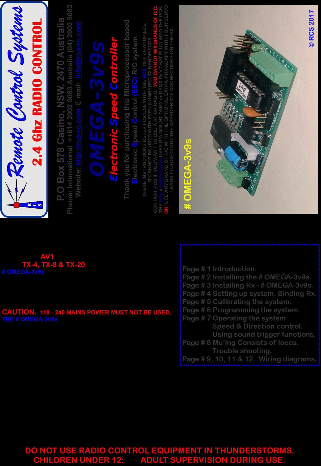
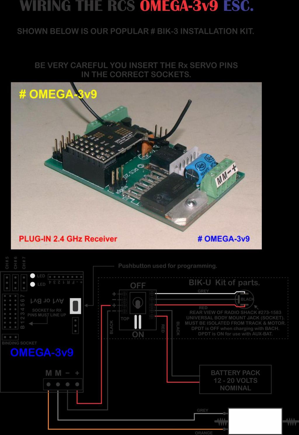
2 - 2 - INSTALLING THE #OMEGA-3v9s ESC. We usually supply the # OMEGA-3v9s ESC with a Lemon brand Rx which is simply plugged in upside down on the ESC pcb in the 24 pin socket. The two parts are bench tested to make sure they work correctly. It is most important the two parts line up correctly. Pin positions are marked on both the back Rx and ESC. Servo leads are not needed. You can obtain the ESC without an Rx supplied and you can use one of your choice. As long as the servo pin outs on the Rx & ESC match. If they do not match, RCS has a prewired adaptor # Rx-ADAPT with four servo cables. THESE INSTRUCTIONS REFER SPECIFICALLY FOR USE WITH THE RCS TX-4, TX-8 & TX-20 HANDPIECES. IT CANNOT BE USED WITH ODD NUMBERED TX HANDPIECES. CONTACT RCS TO USE A STICK RADIO. YOU CAN ONLY MIX BRANDS OF R/C IF THEY ARE DSM2. THE RCS # OMEGA-3v9s SYSTEM IS ONE PART INTO WHICH YOU PLUG ALMOST ANY DSM2 or DSMX RX. OR; USE ANY BRAND OF R/C WITH THE OPTIONAL EXTRA # Rx-ADAPT ON THE ESC AND PLUGGED INTO THE APPROPRIATE CONNECTIONS ON THE RX. PLEASE NOTE. PDF WIRING INSTRUCTIONS ARE HERE: THESE INSTRUCTIONS REFER TO OUR OWN DSM2 TX-8 TX HANDPIECES. CONTROL FUNCTIONS. The TX-4, TX-8 & TX-20 handpieces use a spring loaded SPDT switch for selecting direction change & a large knob for speed control. Apart from direction change, the operation is exactly the same as for the odd numbered TX handpieces. USING EXTRA SERVOS. The # OMEGA-3v9s ESC permits the operation of a regular servo using Ch # 5. Simply plug the servo leads the right way around into the Ch # 5 servo header so marked in the RX. See the ESC diagram. Servo outputs for channels 6 & 7 are available for use only with a 7 channel Tx. SOUND TRIGGER CONTROLS. TX-8. The TX-8 has four pushbuttons on the handpiece that are intended to trigger 4 x sound effects or control accessories. They operate F1, F2, F3 & F4 on this ESC. The Ch 5 pushbutton is available for a servo control feature such as Kadee servo uncoupling. A pushbutton on the ESC pcb is used for initial speed calibration and making system program changes such as Start/Max voltage, default direction start, system reset & sound trigger outputs from momentary to latch ON OFF. If you need to calibrate the system proceed to page # 6. Or: See URL on page # 1. LOCOMOTIVE SEPARATION. 2.4 GHz R/C systems are not separated with crystals. Every TX has a unique identifier code. They are all legal for air & ground use. Most SPEKTRUM RX s (and DSM2/DSMX clones) can be BOUND to the TX-xx handpieces. BINDING must be done before the system can be used. See page # 4. You can mount the # OMEGA-3v9s PCB with double stick tape or non conductive silicone. Do not allow metal objects to touch the rear of the PCB. Damage to the PCB may result. Plug in the Rx. It is most important that pin # s line up.. Push Rx firmly into place for best connectivity. Rx in position. Bend aerials up slightly. PLACING RX ANTENNA. It does not matter where you place the RX and antenna(s). We have at least range with the system in plastic locos. There is NO glitching or Rusty Bolt Effect. 2.4 GHz RX s have been successfully used for some years with the RX & antenna inside a dummy water tank of a live steam loco and inside expensive brass electric locos. Turn the 2.4 GHz TX OFF to save the batteries & the loco will Cruise along until the TX is turned ON again & manual control resumed. N.B. Not the low cost manual bind RX s. They have pre-set Failsafe settings.
 to what were the now isolated track pick ups. The loco will behave exactly as it would if it were running on track power.")

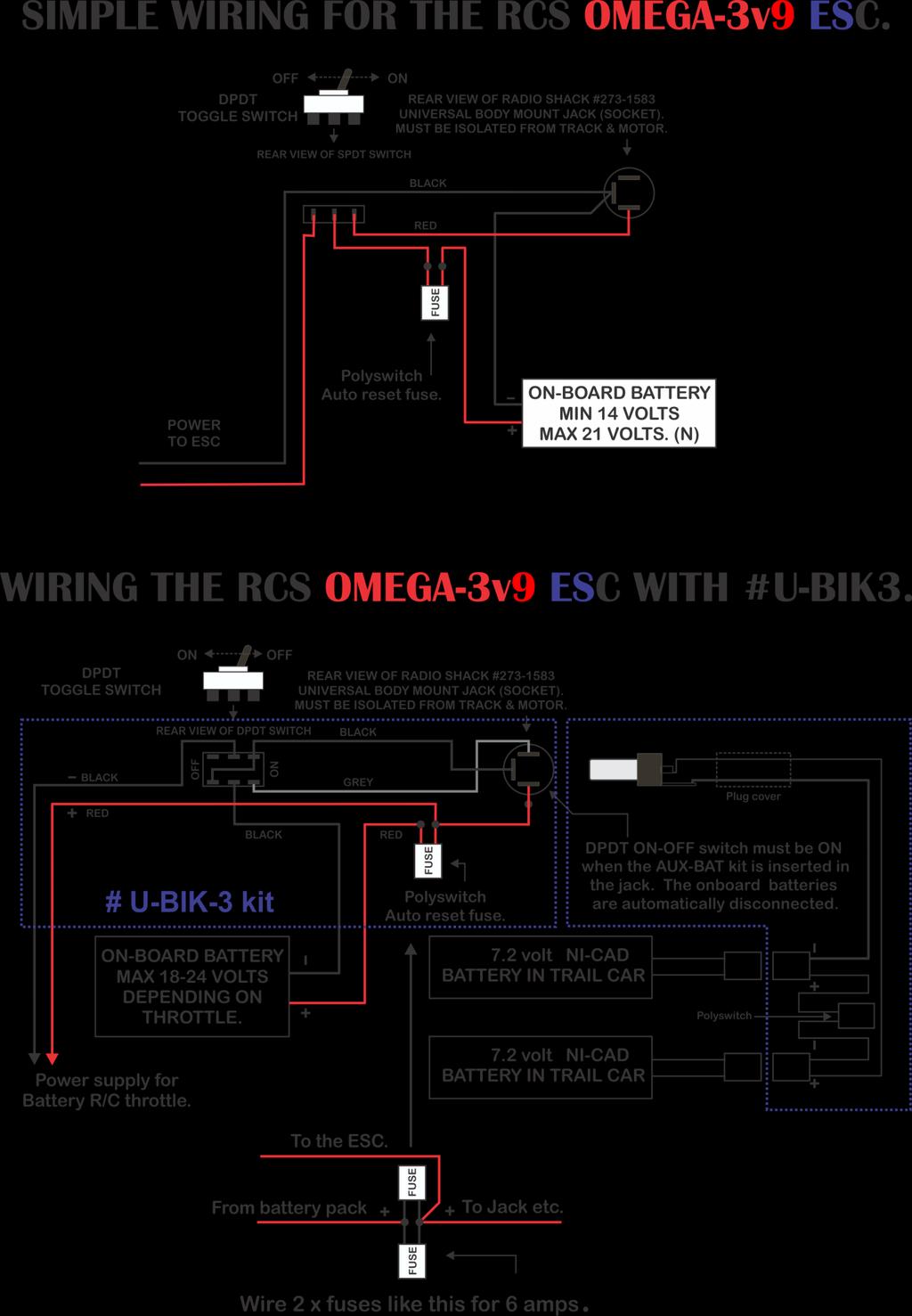
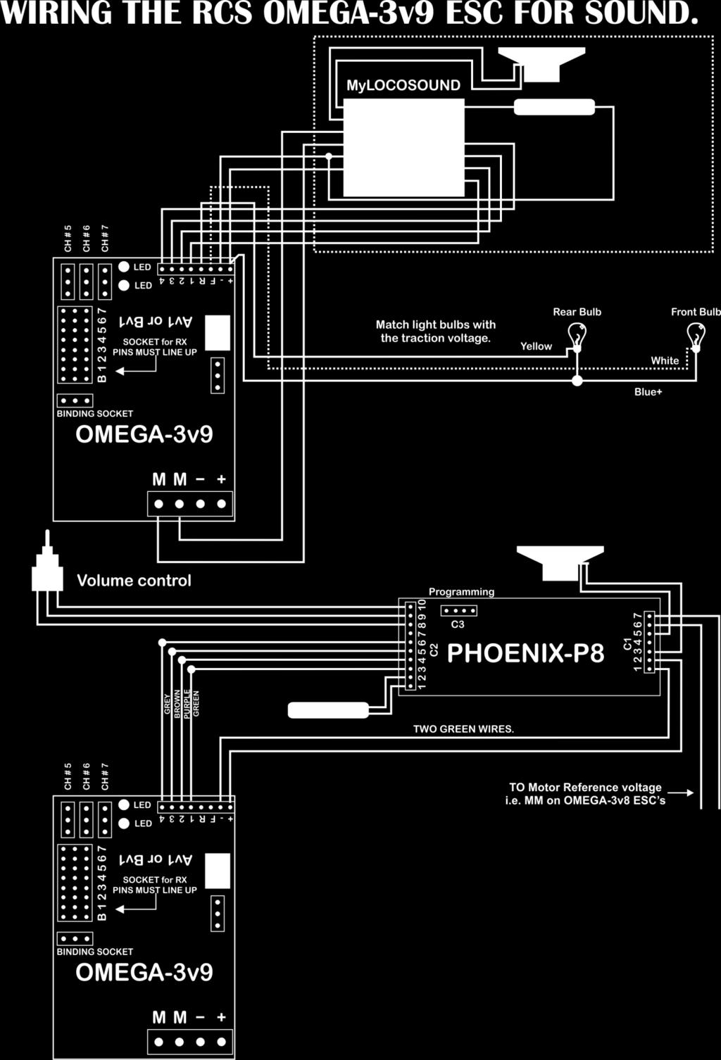
3 - 3 - INSTALLATION OPTIONS. There are a number of different ways to wire up a loco. See wiring diagram pages. The two most popular are: 1. The simplest method is to connect the motor outputs (M & M) to what were the now isolated track pick ups. The loco will behave exactly as it would if it were running on track power. That is, the lights for example will rise and fall with motor voltage or come on before the loco starts moving. No other changes are necessary. This is ideal for trail car set ups. 2. Rewire the lights so that the loco will have constant brightness auto reversing head and tail lights. This can get complicated and is not advised unless the installer has some experience. See below. POWER SOURCES. The #OMEGA-3v9s ESC can only be used with battery power as it comes. Ensure the battery pack is fully charged before use. Contact RCS for information on how to use the ESC with a constant track voltage. N.B. The absolute minimum voltage is 14 volts. If you use any less voltage the system will still respond, as in the LED s will light and respond to direction change, but the motor drive output will not work. Connect the traction battery, which MUST BE FUSED, as per the wiring diagram. RCS R/C offers a variety of installation kits for on board use such as the # BIK-U3/6 which has screw terminals to simplify installations. For trail car installations we also have the # BIK-TC2/3. MOTOR CONNECTION. With #OMEGA-3v9s connect the motor(s) as per the wiring diagrams to M & M. The M + motor output is positive (+) in a forward direction. Our extensive testing has shown the system doesn t need any motor Noise suppression. SHORT CIRCUIT & OVERLOAD PROTECTION. RCS ESC s are self protecting. Although there is output overload and short circuit protection built into them, it is essential the battery supply be fused for overall system protection. See the wiring diagram pages. LOCOMOTIVE LIGHTING. RCS ESC s have transistor controlled directional lighting. Please note: Maximum current is 100 ma per terminal. N.B. Any greater load than 200 ma will kill the switching transistors which are not covered by warranty. 2 3 LED s per output will be just fine but, please do not try and run multiple incandescent bulbs with the outputs.. The #OMEGA-3v9s requires connecting the lights to the 4 x screw terminals as per the ESC diagram. + = Common + voltage (input less.7 volt). - = Common (ground), F = Front Light, R = Rear Light. IT IS MOST IMPORTANT THAT THE LIGHT BULBS BE COMPLETELY ISOLATED FROM ANY OTHER WIRING. Instead of rewiring some locos, sometimes it is much simpler to control the regular loco wiring by simply reversing the traction battery voltage. You can use the # RELAY-1v3 to do this as it can save a lot of wiring in many locos. It is especially useful in USA Trains locos to control incandescent bulbs or LED s up to 1 amp & smoke features. Please note: If the # RELAY-1v3 is used, the lights will flash alternately, not together as with transistor outputs. When the system is in neutral only one set of lights will be lit. The instructions assume the operator has used the available front & rear transistor lighting outputs or # RELAY-1v3. If you do not have any lighting outputs connected you MUST be able to observe the LED s on the ESC. DEFAULT START UP DIRECTION. In case the system is wired back to front, the default direction will also need to be reset. See page # 6 section 3.4. You may also need to reverse the F & R lighting wires. THE PICS BELOW SHOW: 1. Using servos with # OMEGA-3v9k. 2. Plug in Rx-ADAPT allows remote placement of Rx. Ideal for Rx s with end mount servo pins.

 to the Transmitter (TX). AUTOMATIC BINDING. Our # Rx102-1(AB)LR has this feature. Now back in stock. 1.1 Switch on Rx.")

4 - 4 - SETTING UP THE #OMEGA-3v9s ESC. THESE INSTRUCTIONS REFER TO THE RCS TX GHz 5 CHANNEL R/C. FOR BINDING, CALIBRATING & USING WITH A PLANET OR SPEKTRUM STICK RADIO REFER TO: Unless the TX and RX have already been bound and the system calibrated prior to using this system, there are two procedures that must be carried out by the operator, 1. BINDING. The 1 st procedure is to BIND the receiver (RX) to the Transmitter (TX). AUTOMATIC BINDING. Our # Rx102-1(AB)LR has this feature. Now back in stock. 1.1 Switch on Rx. LED will flash once every 2 seconds. Wait 20 seconds until Rx LED flashes rapidly. 1.2 Then press & hold TX bind button & switch TX on. TX LED will flash more slowly for several seconds. When Rx LED starts flashing let go of both TX buttons. 1.3 Bind is complete when Rx LED stays On. 1.4 If the system has been calibrated the ESC LED & both loco lights will immediately blink three times If LED does not come on within 10 seconds or continues flashing every 2 seconds (= scanning), the bind has failed. Switch TX and RX off, move them closer together or further apart and retry. Binding is most reliable when no other 2.4 GHz R/C systems are on. & then go to solid ON. MANUAL BINDING. Simply insert the binding plug into the bind socket on the regular DSM2/DSMX RX. When the RX flashes rapidly follow the RX binding procedure above. Remove the binding plug before commencing operation. When BINDING is complete the RX LED will change to solid ON. If the system has been calibrated the ESC LED & both loco lights will immediately blink three times & then go to solid ON. N.B. If manually binding, the BINDING plug MUST be removed BEFORE the SYSTEM is turned OFF. Once the BINDING plug is removed & stored safely. The R/C system is now ready for speed calibration. Not necessary if already done. Please note the LED s on the ESC pcb & the front and rear lights (if fitted) will stay OFF until BINDING is completed. The loco will always give a very slight jerk at switch ON. This is normal. See Page # 9.


. 2.2 Press and HOLD ESC programming push-button down & turn the ESC/Rx ON.")

5 CALIBRATION. All RCS # OMEGA-3v9s systems are pre-calibrated when sent out, using one of our own TX handpieces. Please test the system before re-calibrating it. If you are going to use a stick type TX, the end points may be different so re-calibration may be necessary. Assuming the RX has been correctly plugged into the ESC the system will perform as described later. The 2 nd step in system preparation is to calibrate the direction & throttle knobs. Even though this step is only needed once when first setting up an uncalibrated ESC, from time to time it is advisable to run through the procedure to ensure the best possible system performance is achieved. A pushbutton is mounted on the pcb for both Calibration & system Programming. See 2.2 below right. You can calibrate & program the system external to the loco by adding the separately available plug in # P-BUTTON. 2.1 Turn the TX ON. Make sure Throttle knob is set to Min. (i.e. fully CCW). 2.2 Press and HOLD ESC programming push-button down & turn the ESC/Rx ON. Release the pushbutton when LED s light. Reaction; Both ESC LED s & both front & rear lights will turn solid ON & stay ON for 6 seconds waiting for the TX and RX to link up. Once linked both ESC LED s & both front & rear lights will flash rapidly. 2.3 Push and pull the toggles switch backwards & forwards a couple of times. Pause briefly each way then let switch spring return to the middle position. 2.4 Rotate throttle knob from Min to Max & back a couple of times. Pause briefly at each extreme then return knob to Min (fully CCW) setting. 2.5 Press & release the ESC pushbutton to exit Calibration mode. Reaction; Both ESC LED s & both loco lights will blink three times at a slower rate & both lights will go to solid ON. The system is in neutral and ready to operate. Either turn the loco and TX OFF for later use, or proceed to page # 6. Please note. Step 2.3 with a TX that has a direction change switch is more or less the same. Just push the direction switch fully backwards and forwards a couple of times.
6 PROGRAMMING WITH TX-8. Operating features of the #OMEGA-3v9s system can be programmed from the TX using the ESC pushbutton. Programming can only take place when the system is in neutral. 3.1 START VOLTAGE. This feature is designed to equalise the starting voltage of dissimilar locos. 3.2 TOP SPEED VOLTAGE. This can limit the top speed available. Either for speed matching locos or, for limiting the top speed of one loco, say, when the system is being operated by children. 3.3 MOMENTUM. Toggle momentum control ON or OFF. 3.4 DEFAULT DIRECTION. Re-set the direction of a loco when it is to run back to back with another loco. 3.5 SYSTEM RESET. This takes # 1 & # 2 back to the factory default if incorrectly set. 3.6/7/8/9 SET SOUND TRIGGERS 1, 2, 3 & 4 from MOM (Default) to Latch ON - OFF. HOW TO USE THE PROGRAMMING FEATURE. Turn the TX & Loco ON. The RX & loco lights will stay OFF until the TX & RX are linked. Then blink 3 x times & go solid ON. The system will then be, & must stay, in neutral. Or, if you have been running, return to neutral before programming. Then press the pcb pushbutton once & the lights will go out. The system is now in Programming Mode. SPEED MATCHING. If you have two or more locos that have dissimilar starting and top speeds, you can adjust those voltages so the locos will be fairly accurately speed matched across the speed range. It has been our experience that absolutely accurate matching is not really needed for smooth performance. The trade off is, the top speed of a consist of locos controlled by one TX will be limited to the top speed of the slowest loco. 3.1 START VOLTAGE. We suggest you test the locos you wish to match one at a time to find out and note the knob setting at which the slowest starting locos begin to move. Then, with the slowest loco stopped and the direction set to neutral: Move the throttle knob to the loco start speed desired. i.e. to the knob position where the loco started moving. Push the direction control switch forwards & back again ONCE only. The lights will blink ONCE with the push. Wait a couple of seconds for the lights to blink ONCE again indicating the new start voltage setting has been stored in the system memory. Then move the large throttle knob back to zero (OFF) position. i.e. knob is fully CCW. Repeat the procedure if the setting is incorrect. 3.2 TOP SPEED VOLTAGE. If speed matching, we suggest you test the locos you wish to match one at a time to find out the knob setting at which the fastest loco matches the top speed of the slowest loco. Then, with the fastest loco stopped and the direction set to neutral: Move the throttle knob to the lower top speed desired for the loco. i.e. to the knob position where the fastest loco matched the top speed of the slowest loco. Push the direction control switch forwards & back again TWICE only. Lights will blink TWICE with the push. Wait a couple of seconds for the lights to blink TWICE again indicating the new top speed voltage setting has been stored in the system memory. Then move the throttle knob back to zero (OFF) position. i.e. knob is fully CCW. Repeat the procedure if the setting is incorrect. OR: When children are using the loco, you can follow the same steps to limit the top speed of any loco. 3.3 MOMENTUM. Toggle momentum control ON or OFF. Use the direction control switch THREE times. Wait a couple of seconds for the lights to blink THREE times again. 3.4 DEFAULT DIRECTION. To re-set the default direction of a loco to run back to back with another loco: Use the direction control switch FOUR times. Wait a couple of seconds for the lights to blink FOUR times again. 3.5 SYSTEM RESET. To take # 3.1 & # 3.2 back to the factory default if incorrectly set: Use the direction control switch FIVE times. Wait a couple of seconds for the lights to blink FIVE times again. 3. 6/7/8/9 SET SOUND TRIGGERS F2, F3 & F4 from MOM (Default) to Latch ON - OFF. # F1 cannot be changed. # F2, Use the direction control switch SEVEN times. Wait a couple of seconds for the lights to blink SEVEN times. # F3 Use the direction control switch EIGHT times. Wait a couple of seconds for the lights to blink EIGHT times. # F4 Use the direction control switch NINE times. Wait a couple of seconds for the lights to blink NINE times. Repeat procedure to change F2, F3, & F4 x triggers back to MOMENTARY from Latch ON OFF.
7 - 7 - OPERATING THE OMEGA-3v9s ESC. WITH TX-8. THE THROTTLE KNOB MUST BE AT MIN i.e. ALL THE WAY CCW, BEFORE TURNING THE SYSTEM ON. Unless binding, always turn the TX on first. Then turn the loco ON. The loco will give a slight jerk (See page # 8) & the ESC & loco lights will stay OFF. After between 2-8 seconds the TX & RX will recognise each other. The RX LED and both ESC LED s will come ON & not blink. After another 6 seconds both ESC LED s & both front & rear loco lights (if fitted) will blink three times & then all lights will go to solid ON. N.B. In order to select a direction the throttle knob must be at MIN and the system must be in neutral. 4.1 FORWARDS. To select forwards from neutral: TX-8, push the Direction switch fully forwards once & then release it. The Red LED on ESC & rear loco light will go out. The green LED on the ESC pcb & the front loco light will stay ON. If the OMEGA-3v9s ESC default motor & lights direction is incorrect please see Page # 6/7 PROGRAMMING of the full instructions. Use the 3.4 DEFAULT DIRECTION feature to make changes. 4.2 SPEEDING UP. Gently twist the big knob clockwise (CW). Loco will accelerate away after slightly turning the knob. The speed is proportional to the knob position with a small amount of momentum built in to prevent sudden jerky movements. Let the knob go once the desired speed has been reached. The speed will stay the same until the knob is rotated CW or CCW. Min - Max speed takes 2 x seconds. 4.3 SLOWING DOWN. Turn the knob CCW back to the desired speed. Max - Min speed takes 2 x seconds. 4.4 STOPPING. Turn the knob completely CCW back all the way to stop. The ESC LED & front light will be ON. 4.5 REVERSE. You must completely stop the loco first. The Throttle knob must be at Min. (i.e. fully CCW). TX-2/6/8/10, then pull the direction switch fully back once for a full second & release it to return the system to neutral. Both ESC LED s & both front & rear loco lights (if fitted) will go to solid ON. To select reverse: TX-2/6/8/10, pull the direction switch again & release it. The Green LED on ESC & front light will go out. The Red LED on the ESC pcb & the rear light will stay ON. To speed up, slow down & stop in reverse see 4.2 SPEEDING UP, 4.3 SLOWING DOWN & 4.4 STOPPING above. 4.6 APPLYING MOMENTUM. Switch on feature in programming. See page # 6/ Once the direction has been set, pull the direction switch back again for a 30 second momentum feature on both acceleration and braking. 2.3 Press and release the spring loaded direction switch forwards, then ramp up speed 2.4 Press and release the spring loaded direction switch rearwards twice, then ramp up speed CAUTION!!! During use, if the battery voltage drops below 12 volts measured at the ESC IN terminals, loss of control may occur. The ESC may even suddenly reverse without warning.
8 - 8 - THE #OMEGA-3v9s ESC MU ing LOCO CONSISTS. MULTIPLE LOCOS IN A CONSIST. The #OMEGA-3v9s ESC is capable of MU ing multiple locos into one consist of locos. If you intend to do this often we strongly recommend you use the # DSM2-EM(AB) in all locos. These bind automatically which is much easier to use than a binding plug. It is also a good idea to purchase the optional extra # LED 3mm-G so you can observe externally what the RX is doing during binding. Add as many speed matched locos to the loco consist, as you like. Each loco must be bound to the controlling TX. Follow the BINDING procedure described above on page # 4. Remember the loco lights will be off during binding. The lights come on once binding has been completed. This is intended as a confirming reference action. If the loco to be added has already been speed calibrated, there is no need to repeat the calibration step. The operating program permits reversing default direction & speed matching of locos. Settings for these features are stored in the ESC so that any loco can be acquired by any TX. See page # /2/4. HOW TO ADD LOCOS TO A CONSIST. Turn the first loco OFF. Turn the second loco ON and drive it into position. Turn the first loco back ON. The lock in feature of the system ensures the direction is set positively. Just make sure both locos are at zero output before changing direction. To make sure the direction is set correctly for all locos in the consist, twist the direction knob twice from neutral. Once the direction is set it cannot accidentally change back to neutral when loco is running. DELETING LOCOS FROM A CONSIST. Turn OFF the to be retained loco. Leave the to be deleted loco ON & drive it away, or, rebind it to a different TX for use by another operator. See page # 4. THE #OMEGA-3v9s ESC TROUBLESHOOTING. IF NOTHING WORKS AT ALL: WHAT TO EXPECT WHEN FIRST TURNING THE SYSTEM ON. WHEN THE LOCO IS SWITCHED ON, THE PCB LED s DO NOT LIGHT OR BLINK. This is most likely caused by the throttle knob not being at MIN. Turn the knob fully CCW to MIN. WHEN THE LOCO IS SWITCHED ON THE LOCO MAY JERK SLIGHTLY. This is normal. The slight jerk indicates power is connected to the system, the IC has powered up and output power is connected to the motor.. NEVER PRESS THE ESC PUSHBUTTON WITH THE LOCO TURNED ON UNLESS YOU INTEND TO CALIBRATE OR PROGRAM THE SYSTEM PROBLEM. You pressed the pushbutton to exit Calibration mode but the lights keep on flashing. You may have mis-plugged the RX servo leads into the channel sockets. SOLUTION. Turn system OFF. Remove & replace the RX servo leads into the correct channel # sockets. As odd things can happen if this occurs, we strongly suggest you reset the system. See page # Then re-calibrate the speed and direction settings. See page # 5. WHEN THE SYSTEM IS FIRST TURNED ON, THE LIGHTS UNEXPECTEDLY BLINK RAPIDLY. This is because you actually pressed the ESC pushbutton & the system has entered calibration mode. CAUTION: DO NOT PRESS THE ESC PUSHBUTTON. You will lose any previous calibration settings. You can proceed with system Calibration. (See page # 5 of the instructions). OR: SOLUTION Turn RX OFF & ON again. Normal system control will be restored. WHEN THE LOCO IS SWITCHED ON, ALL LIGHTS COME ON WITHOUT BLINKING & NOTHING WORKS. This can occur when the TX is switched ON after the loco, with the throttle knob not fully OFF (down). SOLUTION. Ensure the throttle knob is completely OFF. The lights will then blink to indicate linking. THE LOCO DIRECTION SET SWITCH OR KNOB IS BACKWARDS. When the direction is set to forwards the front light must come ON. If the lighting is correct and the speed is backwards, you must reverse the wiring to the motor(s). WEIRD ESC BEHAVIOUR FOR NO APPARENT REASON, DURING OPERATION. If the lights start flashing during operation, stop the loco. Turn it OFF and then ON again to resume normal operation. PLEASE ADVISE US OF ANY OTHER PROBLEMS ENCOUNTERED & WE WILL INCLUDE THEM HERE.
9
10
11
12
INSTALLING THE #OMEGA-3v9k ESC.
 - 2 - INSTALLING THE #OMEGA-3v9k ESC. We usually supply the # OMEGA-3v9k ESC with a Lemon brand Rx which is simply plugged in upside down on the ESC pcb in the 24 pin socket. The two parts are bench tested
OMEGA-3v8s Electronic Speed Controller
 P.O Box 578 Casino, NSW, 2470 Australia Phone: International ++614 2902 9083 Australia (04) 2902 9083 Website: http://rcs-rc.com E mail: Info@rcs-rc.com OMEGA-3v8s Electronic Speed Controller FULL INSTRUCTION
INSTRUCTIONS. DO NOT CONNECT TO MAINS POWER ( V AC).
.") P.O Box 578 Casino, NSW, 2470 Australia Phone: International ++614 2902 9083 Australia (04) 2902 9083 Website: http://rcs-rc.com E mail: Info@rcs-rc.com OMEGA-3v5k Electronic Speed Controller FULL INSTRUCTION
P.O Box 578 Casino, NSW, 2470 Australia Phone: International ++614 2902 9083 Australia (04) 2902 9083 Website: http://rcs-rc.com E mail: Info@rcs-rc.com OMEGA-3v5k Electronic Speed Controller FULL INSTRUCTION
OMEGA-3v7 Electronic Speed Controller
 P.O Box 578 Casino, NSW, 2470 Australia Phone: International ++614 2902 9083 Australia (04) 2902 9083 Website: http://rcs-rc.com E mail: Info@rcs-rc.com OMEGA-3v7 Electronic Speed Controller FULL INSTRUCTION
USE ONLY OPERATING PROGRAM BV1. DO NOT CONNECT TO MAINS POWER ( V AC).
.") P.O Box 578 Casino, NSW, 2470 Australia Phone: International ++614 2902 9083 Australia (04) 2902 9083 Website: http://rcs-rc.com E mail: Info@rcs-rc.com # PnP-3s Electronic Speed Controller FULL INSTRUCTION
P.O Box 578 Casino, NSW, 2470 Australia Phone: International ++614 2902 9083 Australia (04) 2902 9083 Website: http://rcs-rc.com E mail: Info@rcs-rc.com # PnP-3s Electronic Speed Controller FULL INSTRUCTION
INSTRUCTIONS. DO NOT CONNECT TO MAINS POWER ( V AC).
.") P.O Box 578 Casino, NSW, 2470 Australia Phone: International ++614 2902 9083 Australia (04) 2902 9083 Website: http://rcs-rc.com E mail: Info@rcs-rc.com TABLE OF CONTENTS PROVIDED IN INSTRUCTIONS. Page
P.O Box 578 Casino, NSW, 2470 Australia Phone: International ++614 2902 9083 Australia (04) 2902 9083 Website: http://rcs-rc.com E mail: Info@rcs-rc.com TABLE OF CONTENTS PROVIDED IN INSTRUCTIONS. Page
INSTRUCTIONS. DO NOT CONNECT TO MAINS POWER ( V AC).
.") P.O Box 578 Casino, NSW, 2470 Australia Phone: International ++614 2902 9083 Australia (04) 2902 9083 Website: http://rcs-rc.com E mail: Info@rcs-rc.com ALPHA-3v2 Electronic Speed Controller Supplied for
P.O Box 578 Casino, NSW, 2470 Australia Phone: International ++614 2902 9083 Australia (04) 2902 9083 Website: http://rcs-rc.com E mail: Info@rcs-rc.com ALPHA-3v2 Electronic Speed Controller Supplied for
INSTRUCTIONS. DO NOT CONNECT TO MAINS POWER ( V AC).
.") P.O Box 578 Casino, NSW, 2470 Australia Phone: International ++614 2902 9083 Australia (04) 2902 9083 Website: http://rcs-rc.com E mail: Info@rcs-rc.com TABLE OF CONTENTS PROVIDED IN INSTRUCTIONS. Page
P.O Box 578 Casino, NSW, 2470 Australia Phone: International ++614 2902 9083 Australia (04) 2902 9083 Website: http://rcs-rc.com E mail: Info@rcs-rc.com TABLE OF CONTENTS PROVIDED IN INSTRUCTIONS. Page
INSTALLING RCS-BELTROL ESC s.
 - 2 - INSTALLING RCS-BELTROL ESC s. PLANET IS A GROUP A R/C & THIS ESC MUST USE THE BTLvA2 OPERATING PROGRAM. RCS-BELTROL R/C ESC s can use a PLANET T5 5 channel 2.4 GHz digital proportional R/C R6M RX
INSTALLING RCS-BELTROL ESC s.
 - 2 - INSTALLING RCS-BELTROL ESC s. E-SKY IS A GROUP B R/C & THIS ESC MUST USE THE BTLvB1 OPERATING PROGRAM. RCS-BELTROL ESC s can use E-SKY ET61 6 channel 2.4 GHz digital proportional R/C. These instructions
INSTALLING RCS-BELTROL ESC s.
 - 2 - INSTALLING RCS-BELTROL ESC s. HOBBY KING IS A GROUP B R/C & THIS ESC MUST USE THE BTLvB1 OPERATING PROGRAM. RCS-BELTROL ESC s can use a HK TR6a 6 channel 2.4 GHz digital proportional R/C TX & RX
TX-1 Digital Proportional R/C
 P.O Box 578 Casino, NSW, 2470 Australia Phone: International ++614 2902 9083 Australia (04) 2902 9083 Website: http://rcs-rc.com E mail: info@rcs-rc.com TX-1 Digital Proportional R/C TABLE OF CONTENTS
CAUTION DO NOT ATTEMPT TO ALTER THE TUNING OF THE RADIO EQUIPMENT. DO NOT USE RADIO CONTROL EQUIPMENT IN THUNDERSTORMS.
 P.O Box 578 Casino, NSW, 2470 Australia Phone: International ++614 2902 9083 Australia (04) 2902 9083 Website: http://rcs-rc.com E mail: info@rcs-rc.com TX-3 Digital Proportional R/C TABLE OF CONTENTS
AUSTRALIA (04) PHONE: INTERNATIONAL # MRW-SSLS
 PHONE: INTERNATIONAL # MRW-SSLS") R/C SWITCHES PO BOX 8 BAYSWATER, VIC 353, AUSTRALIA PHONE: INTERNATIONAL ++64 2902 9083 AUSTRALIA (04) 2902 9083 Web: http://www.rcs-rc.com Email: rcs@rcs-rc.com # MRW-SSLS # MRW-SSLS by Model Radio Workshop
R/C SWITCHES PO BOX 8 BAYSWATER, VIC 353, AUSTRALIA PHONE: INTERNATIONAL ++64 2902 9083 AUSTRALIA (04) 2902 9083 Web: http://www.rcs-rc.com Email: rcs@rcs-rc.com # MRW-SSLS # MRW-SSLS by Model Radio Workshop
DTRx31d Instructions VERSION: GENERAL:
 DTRx31d Instructions DelTang YouTube Channel: http://www.youtube.com/user/now4dt DelTang website: http://www.deltang.co.uk The Rx31d is a 4 channel receiver unit for use with micro servos. To save weight
CAUTION-ELECTRICALLY OPERATED PRODUCT
 CAUTION-ELECTRICALLY OPERATED PRODUCT NOT RECOMMENDED FOR CHILDREN UNDER 14 YEARS OF AGE. AS WITH ALL ELECTRIC PRODUCTS, PRECAUTIONS SHOULD BE OBSERVED DURING HANDLING AND USE TO PREVENT ELECTRIC SHOCK.
PHOENIX HV Features of the Phoenix HV-45 : 2.3 Connecting the Motor. 2.4 Reversing Rotation. 2.5 Connecting the Receiver
 PHOENIX HV -45 1.0 Features of the Phoenix HV-45 : Extremely Low Resistance (.003 ohms) High rate adjustable switching (PWM) Up to 45 Amps continuous current Dual Opto-Coupled (No BEC) Up to 36 cells or
PHOENIX Features of the Phoenix-10 : 2.3 Connecting the Motor. 2.4 Reversing Rotation. 2.5 Connecting the Receiver
 Warning! High power motor systems can be very dangerous! High currents can heat wires and batteries, causing fires and burning skin. Follow the wiring directions carefully! Model aircraft equipped with
PHOENIX Features of the Phoenix-25 : 2.3 Connecting the Motor. 2.4 Reversing Rotation. 2.5 Connecting the Receiver
 Warning! High power motor systems can be very dangerous! High currents can heat wires and batteries, causing fires and burning skin. Follow the wiring directions carefully! Model aircraft equipped with
RR Concepts. The StationMaster can control DC trains or DCC equipped trains set to linear mode.
 Jan, 0 S RR Concepts M tation aster - 5 Train Controller - V software This manual contains detailed hookup and programming instructions for the StationMaster train controller available in a AMP or 0AMP
Caution Notes. Features. Specifications. Installation. A3 3-axis Gyro & Stabilizer User Manual V1.0
 Caution Notes Thank you for choosing our products. If any difficulties are encountered while setting up or operating it, please consult this manual first. For further help, please don t hesitate to contact
Operation and Installation Manual
 Operation and Installation Manual G-Scale Graphics 4118 Clayton Ct. Fort Collins, CO 80525 970-581-3567 GScaleGraphics@comcast.net www.gscalegraphics.net Revision C: Updated 7/15/2009 Page Overview The
MPI MX-9900 SUPER GLOW On-board Glow Driver
 MPI SUPER GLOW On-board Glow Driver Congratulations on your purchase of the SUPER-GLOW on-board glow driver. This an advanced on-board glow driver offering unique features. is very different from other
PHOENIX ENIX Features of the Phoenix-60 : 2.3 Connecting the Motor. 2.4 Reversing Rotation. 2.5 Connecting the Receiver
 PHOENIX ENIX-60 Warning! High power motor systems can be very dangerous! High currents can heat wires and batteries, causing fires and burning skin. Follow the wiring directions carefully! Model aircraft
INSTALLATION MANUAL SPECTRUM BRAKE CONTROL
 INSTALLATION MANUAL 51170 SPECTRUM BRAKE CONTROL TABLE OF CONTENTS Controls & Components Tools List Before You Begin Wiring Wiring Diagram Mounting the LED Display Rotary Knob Wiring the Plug Connector
30A BLDC ESC. Figure 1: 30A BLDC ESC
 30A BLDC ESC Figure 1: 30A BLDC ESC Introduction This is fully programmable 30A BLDC ESC with 5V, 3A BEC. Can drive motors with continuous 30Amp load current. It has sturdy construction with 2 separate
Fitting Radio Control to a Mamod Boulton
 Fitting Radio Control to a Mamod Boulton How To Fit Radio Control To A Mamod Boulton using FlySky Equipment I assume that you already have a Mamod Boulton and have fitted rechargeable AA batteries instead
HYDRA 120 & HYDRA 240 OPERATION MANUAL
 HYDRA 120 & HYDRA 240 OPERATION MANUAL The battery connector must be added to the power side of the controller (black capacitors, receiver connector, and red and black wire side). The red wire is the positive
Features: Enhanced throttle response, excellent acceleration, strong brakes and throttle linearity. Using LED program card to make adjustments.
 Thank you for purchasing the ZTW Brushless Electronic Speed Controller (ESC). The ZTW 1:10 Scale BEAST Series ESC is specifically designed for operating 4 Pole Sensorless brushless motors. This is a high
Features: Enhanced throttle response, excellent acceleration, linearity and driveability
 120A/150A ESC X-Car 120A/150A Series Sensored/Sensorless Brushless ESC for 1:8 scale Car or Truck Thank you for purchasing the X-Car Brushless Electronic Speed Controller (ESC). The X-Car 1:8 Scale 120A/150A
Operation and Installation Manual
 Operation and Installation Manual G-Scale Graphics 5860 Crooked Stick Dr. Windsor, CO 80550 970-581-3567 GScaleGraphics@comcast.net www.gscalegraphics.net Revision A: Updated 2/7/2018 Page Overview The
Model 1:8 Beast-ZTWSS120A 1:8 Beast-ZTWSS150A. PN#Model Cont.Current 120A 150A. Burst Current 760A 1080A
 Alien Power System BEAST Series Sensored/Sensorless Brushless ESC for 1:8 scale Car or Truck Thank you for purchasing the Alien Power System Brushless Electronic Speed Controller (ESC). The Alien Power
Begin to Use The New ESC: Before use the new ESC please carefully check every connections are correct or not. Yellow motor wire B Blue motor wire A
 HIMOTO ZTW Brushless Electronic Speed Control for car or truck Thank you for purchasing ZTW Brushless Electronic Speed Controller(ESC). The ZTW electronic speed control (ESC) is specifically designed for
USER MANUAL BRUSHLESS SPEED CONTROLLER S5-RTR ESC S5A-RTR ESC RC CARS & TRUCKS
 USER MANUAL BRUSHLESS SPEED CONTROLLER S5-RTR ESC S5A-RTR ESC RC CARS & TRUCKS Declaration Thanks for purchasing our Electronic Speed Controller (ESC). High power system for RC model can be very dangerous,
PHOENIX Amp Brushless Sensorless Speed Control. 1.0 Features of the Phoenix-25 : 2.3 Connecting the Motor. 2.4 Reversing Rotation
 1.0 Features of the Phoenix-25 : Extremely Low Resistance (.013 ohms) High rate (7 KHz) switching (PWM) Up to 25 Amps continuous current with proper air flow, 35 amps surge Five to eight cells with four
Throttle Setup by Jason Priddle
 Throttle Setup by Jason Priddle This article is written around JR Radio convention. The numbers noted are for illustrative purposes, and the same principles apply to all radios Ever feel like all your
INSTALLATION GUIDE Table of Contents
 CT-3100 Automatic transmission remote engine starter systems. What s included..2 INSTALLATION GUIDE Table of Contents Door lock toggle mode..... 4 Notice...2 Installation points to remember. 2 Features..2
BASIC TROUBLE SHOOTING (PERFECTPASS FOR MECHANICAL ENGINES) How PerfectPass Works
 How PerfectPass Works") BASIC TROUBLE SHOOTING (PERFECTPASS FOR MECHANICAL ENGINES) How PerfectPass Works Through the in-dash display the driver sets the desired boat speed or engine RPM depending upon which mode of operation
BASIC TROUBLE SHOOTING (PERFECTPASS FOR MECHANICAL ENGINES) How PerfectPass Works Through the in-dash display the driver sets the desired boat speed or engine RPM depending upon which mode of operation
Caution! Caution! Air/CO2 and Electric Shift Devices
 Caution! Caution! Air/CO and Electric Shift Devices You must set rpm in the CHEETAH E-SHIFT Controller before starting vehicle! Failure to do this could cause injury and or property damage! Read Instructions
Azatrax MRX3 Grade Crossing Signal Controller Installation Guide
 Azatrax MRX3 Grade Crossing Signal Controller Installation Guide What it is: The MRX3 is a sophisticated controller that realistically operates model railroad / highway crossing signals. The MRX3 includes
Climber is 776B101101
 is Climber 776B101101 Introduction Product Introduction NE R/C 776B is a good-sized glider designed by Nine Eagles Company latest, whose wing span is up to 2008mm. You only need to assemble the aerofoil
Galileo with wifi RADIO CONTROLLED QUAD-COPTER
 Galileo with wifi TM RADIO CONTROLLED QUAD-COPTER FEATURING: 1. Four-Rotor design allows great speed and maneuverability for both Indoor and Outdoor use. 2. Built-in 6-axis Gyro ensures excellent stability.
DTS SECURITY P.O.BOX 3399 EDENVALE 1610 Base plate-mounting instructions TELEPHONE
 DTS ECO 500 SLIDING GATE MOTOR INSTALLATION MANUAL DTS SECURITY P.O.BOX 3399 EDENVALE 1610 Base plate-mounting instructions TELEPHONE 086 1000 387 Spartan +2711 392 5540 (H/O) Pretoria +2712 361 5528 Alberton
RPK-1 RailPro Model Railroad Control System Starter Kit
 RPK-1 RailPro Model Railroad Control System Starter Kit User Manual Ring Engineering Inc. (219) 322-0279 www.ringengineering.com Revision 2.01 Copyright 2017 Ring Engineering Inc. All rights reserved.
mz-12 & GR-18 Setup Tutorial
 mz-12 & GR-18 Setup Tutorial INTRODUCTION Thank you for purchasing the mz-12 COPTER radio. This radio is the first of its kind that lets you fly your multirotor without the need of complex setups, computer
EtronixPulseRXInstructions 6/6/11 09:17 Page 1
 EtronixPulseRXInstructions 6/6/11 09:17 Page 1 EtronixPulseRXInstructions 6/6/11 09:17 Page 2 Etronix Pulse EX2 Sport 2 Channel 2.4GHz Steer Wheel Transmitter 1) INTRODUCTION. Thank you for choosing this
Galileo RADIO CONTROLLED QUAD-COPTER
 Galileo TM RADIO CONTROLLED QUAD-COPTER FEATURING: 1. Four-Rotor design allows great speed and maneuverability for both Indoor and Outdoor use. 2. Built-in 6-axis Gyro ensures excellent stability. 3. Modular
CI 3000 Coil Inserter
 CI 3000 Coil Inserter Setup & Operator Manual Issue 1 April 02 Performance Design Inc. The CI 3000 plastic spiral inserter will bind books up to 1-1/8 (28.6mm) thick using coil diameters from 3/16 (5mm)
 Introduction Thank you for purchasing a Redcat P-51 model R/C aircraft! Headquartered in Phoenix, AZ; Redcat Racing is proud to have become the premier source for quality Gas, Nitro and Electric powered
1. Disclaimer Warnings Introduction Display and Commands... 5
 1. Disclaimer... 1 2. Warnings... 2 2.1. Welding... 2 3. Introduction... 3 4. Display and Commands... 5 4.1. Status Display on LCD... 5 4.1.1. Control Mode... 6 4.1.2. Bowl Mode... 6 4.1.3. Engine Mode...
REC-11+ REMOTE RECEIVER UNIT
 Resetting The Programmable Features The installer may quickly and easily return all 17 programmable features back to the factory settings. Changing individual features were explained in detail in the previous
HC Model Railroad Handheld Controller
 HC Model Railroad Handheld Controller User Manual Ring Engineering Inc. (219) 322-0279 www.ringengineering.com Revision 2.00 Copyright 2017 Ring Engineering Inc. All rights reserved. Introduction...3 Warnings...3
Sectional And Tilting Door Opener
 Sectional And Tilting Door Opener Installation Instructions and User Guide FS 600 FS 1000 FS 1200 600N 1000N 1200N FS 600-Speed FS 1000-Speed 600N 1000N S/N WARNING Please read the manual carefully before
Advanced Troubleshooting Guide Snorkel V Battery Charger Rev 0 3JAN07
 Advanced Troubleshooting Guide Snorkel 3050097 24V Battery Charger Rev 0 3JAN07 1. How It Works: The 3050097 charger converts AC voltage to DC voltage, then uses high frequency to re-convert it to DC voltage/current
AS RW BEC TRUCK LIPO User Manual ver 1.00
 ` To Receiver AS-12-40 RW BEC TRUCK LIPO User Manual ver 1.00 5-12 Cell 40 A For/Rev 2 A BEC Batt - Motor- Reverse Light Batt + Brake Light Motor+ Features: Operating Voltage: 5-12 Nimh/Nicad Cells or
Installation and Maintenance Instructions. World Leader in Modular Torque Limiters. PTM-4 Load Monitor
 World Leader in Modular Torque Limiters Installation and Maintenance Instructions PTM-4 Load Monitor 1304 Twin Oaks Street Wichita Falls, Texas 76302 (940) 723-7800 Fax: (940) 723-7888 E-mail: sales@brunelcorp.com
 Introduction Thank you for purchasing a Redcat JETiger Ducted-Fan Aircraft! Headquartered in Phoenix, AZ; Redcat Racing is proud to have become the premier source for quality Gas, Nitro and Electric powered
4-CHANNEL RADIO CONTROLLED QUAD-COPTER
 DRONIUM TM 4-CHANNEL RADIO CONTROLLED QUAD-COPTER FEATURING: 1. Four-Rotor design allows great speed and maneuverability for both Indoor and Outdoor use. 2. Built-in 6-axis Gyro ensures excellent stability.
IMPORTANT! Remote Control Instructions
 Remote Control Instructions FOR New Tarp Remote Control Installation Use these in place of the rocker switch and solenoid section of instructions in your roll tarp owner s manual. FOR Existing Electric
STEAM MYLOCOSOUND MAY 4 TH 2017
 1 STEAM MYLOCOSOUND MAY 4 TH 2017 UNIVERSAL SOUND FOR LARGE SCALE, DC, STEAM LOCOMOTIVES 1.OVERVIEW Easy installation using screw terminals with no soldering. Uses a TV remote control to adjust the volume
Owner and Operating Manual for
 Owner and Operating Manual for 120VAC Manual Control 12VDC Solar Battery Manual Control 120VAC Remote Control 12VDC Solar Battery Remote Control GEN2 Remote Versions Only Boat Lifts Please read this manual
(Designed & Manufactured by RC EXPLORER TEAM) Radon V2 series Brushless Speed Control System User Guidelines
 Radon V2 series Brushless Speed Control System User Guidelines") (Designed & Manufactured by RC EXPLORER TEAM) Radon V2 series Brushless Speed Control System User Guidelines 1. Technical /Specifications: Model: Radon Pro V2 Radon Pro V2 1S Radon Sport V2 Continuous
(Designed & Manufactured by RC EXPLORER TEAM) Radon V2 series Brushless Speed Control System User Guidelines 1. Technical /Specifications: Model: Radon Pro V2 Radon Pro V2 1S Radon Sport V2 Continuous
Arrow Shark 2015 E-Starter V4 Owner Manual
 Arrow Shark 2015 E-Starter V4 Owner Manual The Arrow Shark E-Starter V3 has successfully been available in the market for over three years now. During that time, we have never stopped seeking ways to improve
7C MERGER M40/50RF SYSTEM INSTALLERS GUIDE
 7C MERGER M40/50RF SYSTEM INSTALLERS GUIDE Contents Glossary... 3 M40/50RF Motor... 3 SUITE Remote... 3 Battery Installation... 3 Introduction... 4 1) Install the Shade... 4 2) Create the Hub Motor...
MrRCSound Sound Generator. Version 4.1 for RC Aircraft/Cars/Trucks
 MrRCSound Sound Generator Version 4.1 for RC Aircraft/Cars/Trucks Thank You! Thank you for purchasing the MrRCSound electric aircraft sound module, or other product. I know there are options out there,
VS 315 DELUXE 4-CHANNEL MOTORCYCLE ALARM. Installation And Operation Manual MEGATRONIX CALIFORNIA, U.S.A. VS 315 1
 VS 315 DELUXE 4-CHANNEL MOTORCYCLE ALARM Installation And Operation Manual MEGATRONIX CALIFORNIA, U.S.A. VS 315 1 VS 315 2 INSTALLATION We recommend insulating all your soldered or crimped connections
GETTING STARTED. You are now ready to go!
 I WARNING: This is an extremely powerful brushless motor system. We strongly recommend removing the pinion gear from the motor for your own safety and the safety of those around you before performing calibration
Warning! Before continuing further, please ensure that you have NOT mounted the propellers on the MultiRotor.
 Mission Planner Setup ( optional, do not use if you have already completed the Dashboard set-up ) Warning! Before continuing further, please ensure that you have NOT mounted the propellers on the MultiRotor.
DTS 412/512/624 SLIDING GATE MOTOR INSTALLATION MANUAL
 DTS 412/512/624 SLIDING GATE MOTOR INSTALLATION MANUAL DTS SECURITY P.O.BOX 3399 EDENVALE 1610 TELEPHONE 086 1000 387 Base plate-mounting instructions Alberton 011 907 8846 Centurion 012 653 4434 Edenvale
Only use if safe to do so and at your own risk.
 This product may not be suitable or safe for road usage. The owner accepts ALL responsibility for its use and installation. The product must not be used if malfunction occurs, a suspected malfunction occurs
elabtronics Voltage Switch
 elabtronics Voltage Switch Want to trigger a device when a monitored voltage, temperature or light intensity reaches a certain value? The elabtronics Voltage Switch is an incredibly easy way of doing it.
CONTENTS: Concept Document Layout
 CONTENTS: Concept Document Layout Part 1: Systems 0 50V (AC/DC) Start by reading this covers 95% of scenarios, so put the simple thing first For locomotive construction that utilises power of voltages
GETTING STARTED EASY TO USE, SOPHISTICATED ENOUGH TO WIN EVERYTHING. You are now ready to go!
 WARNING: This is an extremely powerful brushless motor system. We strongly recommend removing the pinion gear from the motor for your own safety and the safety of those around you before performing calibration
USER MANUAL FOR ATLAS HO DUAL-MODE 4-FUNCTION DCC DECODER (ITEM #342)
") HO Dual-Mode 4-Function Decoder 1 USER MANUAL FOR ATLAS HO DUAL-MODE 4-FUNCTION DCC DECODER (ITEM #342) By Dual Mode, we mean that the Atlas #342 HO 4-function decoder has a jumper plug that allows the
HO Dual-Mode 4-Function Decoder 1 USER MANUAL FOR ATLAS HO DUAL-MODE 4-FUNCTION DCC DECODER (ITEM #342) By Dual Mode, we mean that the Atlas #342 HO 4-function decoder has a jumper plug that allows the
NCE DCC TWIN. In addition to the NCE DCC TWIN, you will need:
 NCE DCC TWIN Welcome to the world of DCC! This manual will familiarize you with the set up and operation of two locomotives on your railroad using the NCE DCC TWIN. In addition to the NCE DCC TWIN, you
USER GUIDE - SUPPLEMENTAL
 USER GUIDE - SUPPLEMENTAL CONTENTS 5 Instructions for RX2702V receiver... 2 5.3 Channel connection of receiver... 2 10 Walkera V450D01 Flybarless System Setting RX2702V... 3 10.5 Flybarless system setting...
UNIVERSAL PUSHBUTTON DIMMER ETD 2 (Rail mount version)
") UNIVERSAL PUSHBUTTON DIMMER ETD 2 (Rail mount version) With central control inputs, front button and various operating modes and functions General purpose, user-friendly electronic pushbutton dimmer for
UNIVERSAL PUSHBUTTON DIMMER ETD 2 (Rail mount version) With central control inputs, front button and various operating modes and functions General purpose, user-friendly electronic pushbutton dimmer for
Model 2300JL Installation Guide
 Model 2300JL Installation Guide POWER ACCESS CORPORATION 4 HERSHEY DRIVE, DOCK 4 ANSONIA, CT 06401 800-344-0088 WEBSITE: www.power-access.com EMAIL: salesinfo@power-access.com 1 STANDARD PARTS MODEL 2300JL
CAPTAIN AMERICA 2CH FLYING FIGURE IR HELICOPTER
 I N S T R U C T I O N M A N U A L ITEM NO: 33190 CAPTAIN AMERICA 2CH FLYING FIGURE IR HELICOPTER Stabilizer Bar Main Rotor Blades LED Light PRODUCT INCLUDES: - IR Helicopter - Remote - User Manual - Main
Model 2300DL Installation Guide
 Model 2300DL Installation Guide POWER ACCESS CORPORATION 4 HERSHEY DRIVE, DOCK 4 ANSONIA, CT 06401 800-344-0088 WEBSITE: www.power-access.com EMAIL: salesinfo@power-access.com 1 STANDARD PARTS MODEL 2300DL
Instrument Panel Lights
 Instrument Panel Lights What do they all mean??? By G. Tiberio Instrument Panel Lights Instrument panel lights are used to alert the driver of important information about the vehicle. Can also be used
1) Wire Cutters 1) Solder (Rosin Core Electronic Solder) 2) Wire Strippers 2) Battery Connector 3) watt soldering iron
 Wire Cutters 1) Solder (Rosin Core Electronic Solder) 2) Wire Strippers 2) Battery Connector 3) watt soldering iron") Thank you for purchasing the Electronic Speed Control (ESC). The V-Series ESC Line was designed to offer high power and high efficiency combined with low weight and a compact size. These instructions will
Thank you for purchasing the Electronic Speed Control (ESC). The V-Series ESC Line was designed to offer high power and high efficiency combined with low weight and a compact size. These instructions will
RADIO CONTROLLED QUAD-COPTER WITH CAMERA
 Movie - DRONE TM RADIO CONTROLLED QUAD-COPTER WITH CAMERA FEATURING: 1. Four-Rotor design allows great speed and maneuverability for both Indoor and Outdoor use. 2. Built-in 6-axis Gyro ensures excellent
ECHO. User Manual. Model: PFBD77
 ECHO User Manual Model: PFBD77 Thank you for choosing ProFlight. Please read this user manual before using this drone and keep it safe for future reference. CONTENTS Safety 3 Battery Charging 4 Transmitter
Mini Automotive Controller Installation & Operation Manual
 Mini Automotive Controller Installation & Operation Manual Software Version 3 Draft of 6 June 2004 INTRODUCTION The Mini Automotive Controller (MAC) is a small, multipurpose module designed to improve
Steam Locomotive. v.2
 Steam Locomotive O p e r a t o r s M a n u a l N E OPERATE IN SILENCE NO MORE. 1 MO v.2 Before running your engine: Prior to operation, be sure to perform a reset procedure on your engine as outlined in
ESC. Brushless Controller. Receiver
 ESC instruction Wires Connection: The electronic speed controller can be connected to the motor by soldering directly, or with high quality connectors. Always use new connectors, which should be soldered
DCCDPro. Aftermarket standalone Automatic DCCD Controller for JDM and USDM 6-Speed Transmissions as well as for the older 5-Speed DCCD transmissions.
 Aftermarket standalone Automatic DCCD Controller for JDM and USDM 6-Speed Transmissions as well as for the older 5-Speed DCCD transmissions. What advantages are there in your auto mode controllers vs.
Installation Instructions Jeep CJ-7
 Retrofit Steering Column Installation Instructions 1976-86 Jeep CJ-7 For Part # s 1520800010, 152800020, 1520800051 www.ididitinc.com 610 S. Maumee St., Tecumseh, MI 49286 (517) 424-0577 (517) 424-7293
BASIC ELECTRICAL MEASUREMENTS By David Navone
 BASIC ELECTRICAL MEASUREMENTS By David Navone Just about every component designed to operate in an automobile was designed to run on a nominal 12 volts. When this voltage, V, is applied across a resistance,
RECOMMENDED TOOLS INCLUDED EQUIPMENT PRECAUTIONS
 Thank you for purchasing Pro-Line s Ambush Mini Scale Crawler! For Over 30 years, Pro-Line has designed and manufactured the best RC products in the world. This crawler has been developed from the ground
2007 Losi, A Division of Horizon Hobby Inc.
 Operation Manual Thank you for choosing the Mini-Slider from Losi. This guide contains the basic instructions for operating your new Mini-Slider. While the Mini-Slider is great for first-time R/C drivers,
(Designed & Manufactured by RC EXPLORER TEAM) XPS Brushless Speed Control System User Guidelines
 XPS Brushless Speed Control System User Guidelines") (Designed & Manufactured by RC EXPLORER TEAM) XPS Brushless Speed Control System User Guidelines 1. Technical /Specifications: Model: XPS- Pro XPS-Sport XPS-EL Continuous current: 140A 70A 35A Burst Current
(Designed & Manufactured by RC EXPLORER TEAM) XPS Brushless Speed Control System User Guidelines 1. Technical /Specifications: Model: XPS- Pro XPS-Sport XPS-EL Continuous current: 140A 70A 35A Burst Current
An Actual Driving Lesson. Learning to drive a manual car
 An Actual Driving Lesson Learning to drive a manual car Where are the controls that I might have to use in my driving: Knowing where the controls are, and being able to locate and use them without looking
PRODUCT MANUAL Gecko Wireless 2 Zone LED Dimmer and Receiver
 Product Description The Gecko Wireless 2 Zone Wall LED Dimmer has been designed to bring light control easily. No wires or switch box locations are needed, just stick or mount the Gecko to any flat location
INSTALLATION GUIDE. FCC ID NOTICE
 REV.5 RS. ADVANCED REMOTE STARTER INSTALLATION GUIDE www.security.soundstream.com FCC ID NOTICE This device complies with Part 5 of the FCC rules. Operation is subject to the following conditions:. This
Aftermarket Interface Module
 An ISO 9001:2008 Registered Company Aftermarket Interface Module (2015-2018 Ford Transit) AIM514-B High Side Solenoid type Coolant Valve Control AIM515-B Motor Reversing type Coolant Valve Control Introduction
L I M I T E D L I F E T I M E W A R R A N T Y
 L I M I T E D L I F E T I M E W A R R A N T Y Products manufactured and sold by OMEGA RESEARCH & DEVELOPMENT, INC. (the Company), are warranted to be free from defects in materials and workmanship under
RATE CONTROLLED TORQUE WRENCH TESTER
 RATE CONTROLLED TORQUE WRENCH TESTER OPERATOR S HANDBOOK (PART NO. 34078) ISSUE 8 NORBAR TORQUE TOOLS LTD, Beaumont Road, Banbury, Oxfordshire, OX16 1XJ, UNITED KINGDOM Tel : + 44 (0) 1295 270333, Fax
INSTRUCTIONS FOR TRI-METRIC BATTERY MONITOR May 8, 1996
 INSTRUCTIONS FOR TRI-METRIC BATTERY MONITOR May 8, 1996 PART 2: SUPPLEMENTARY INSTRUCTIONS FOR SEVEN TriMetric DATA MONITORING FUNCTIONS. A: Introduction B: Summary Description of the seven data monitoring