Mounting Instructions for High Power Modules. Mounting Instruction
|
|
|
- Ashlyn Campbell
- 5 years ago
- Views:
Transcription


1 Mounting Instructions for High Power Modules Mounting Instruction Oct MTXXXXXXX

2 CONTENTS 1. Scope 2 2. The surface of the heat sink 3 3. Thermal grease application 3 4. Clamping 3 1
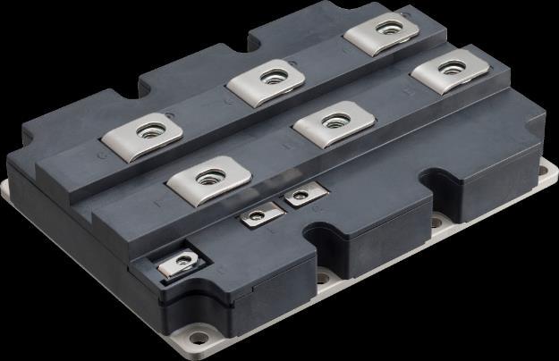
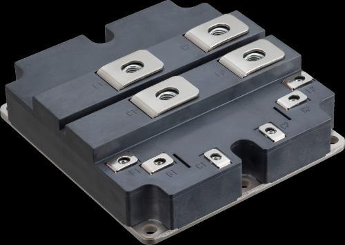
3 1. Scope This document describes about recommended mounting procedures for M151/M152/M155/M156/M256/M278 packages. This mounting instruction is available only for the following modules. 1MBIxxxxVC-120P/1MBIxxxxVC-170E (M151 package) 1MBIxxxxVD-120P/1MBIxxxxVD-170E (M152 package) 1MBIxxxxVR-170E/1MBIxxxxUG-330x (M155 package) 1MBIxxxxVS-170E/1MBIxxxxUE-330x (M156 package) 2MBIxxxxVG-120P/2MBIxxxxVG-170E (M256 package) 2MBIxxxxVT-170E (M278 package) (ex. 1MBI1200VC-120P) Note: M151/M152/M256 package Cu-baseplate M155/M156/M278 package AlSiC-baseplate 2
4 2. The surface of the heat sink Please keep the following surface about the heat sink surface to attach IGBT. Flatness 50um(Sampling frequency=100mm) Surface Rz 10um When mounting (when tightened it) IGBT module when a heat sink surface is out of the range mentioned above, the ceramic (insulation board) which there is between the chip in the IGBT module and a metal base increases stress and might break this module. When the plane of the heat sink becomes hollow, CTR (contact thermal resistance) may increase 3. Thermal grease application Please apply thermal grease between a heat sink and the mounting surface of the IGBT module to decrease CTR. Please apply the thermal grease on appropriate thickness. When an application thickness of the thermal grease is inappropriate, the heat radiation to a fin worsens, and it may lead to destruction that chip temperature exceeds T vjmax. As an application method of the thermal grease, we recommend the application method with the stencil mask. (This is because application on the thickness that is uniform on the module back side is possible) The figure 1 show an outline of the thermal grease application method. The figure 2,3 shows the example of the stencil mask. The IGBT module which thermal paste was applied to is attached to a heat sink, and, please tighten a screw by recommended torque. When a thermal grease thickness is uniform, it can calculate the necessary weight as follows. Thermal grease thickness (um) = Weight of thermal grease (g) x 10 4 Baseplate area of IGBT module (cm 2 ) x Density of thermal grease (g/cm 3 ) The thickness of the thermal grease recommends 100um. Model name: HTC01K Manufacturer: ELECTROLUBE The most suitable application thickness of the thermal grease changes by a characteristic and an application method of the thermal grease to use. Please use it after confirming it. 4. Clamping The figure 4,5 show a clamping sequence of the screws for the mounting IGBT module. Please tighten the screw by prescribed clamping torque. (Please refer to each model specification for the prescribed torque.) When torque is short, a module might be warped during movement, and CTR might grow big. When torque is excessive, a case might be broken. 3


 9.")

5 1.Back to Room Temp. 2.Mesure weight of IGBT 3.Adjust zero 2 guide pins for IGBT 4 guide pins for Frame 4 guide holes for bottom tool 4.Bottom tool 5.Set IGBT module 6.Metal mask and Frame 7.Fix tools and put grease with Knife 8. Print with metal squeegee (begin) 9. Print with metal squeegee (end) 10.After printing 11. Open metal mask 12. Check grease weight Figure 1. Outline of the thermal grease application method 4

6 Figure 2. The example of the stencil mask for M151/M155/M256/M278 packages Figure 3. The example of the stencil mask for M152/M156 packages 5

 specified torque 1/3 2 6 3 7 4 8 1 5 The")
7 torque sequence The first (Temporary clamping) specified torque 1/ The second specified torque Figure 4. Clamping sequence of the screws for the M151/M155/M256/M278 packages torque sequence The first (Temporary clamping) specified torque 1/ The second specified torque Figure 5. Clamping sequence of the screws for the M152/M156 packages. 6
8 Warning: This manual contains the product specifications, characteristics, data, materials, and structures as of Oct The contents are subject to change without notice for specification changes or other reasons. When using a product listed in this manual, be sure to obtain the latest specifications. All applications described in this manual exemplify the use of Fuji's products for your reference only. No right or license, either express or implied, under any patent, copyright, trade secret or other intellectual property right owned by Fuji Electric Co., Ltd. is (or shall be deemed) granted. Fuji Electric Co., Ltd. makes no representation or warranty, whether express or implied, relating to the infringement or alleged infringement of other's intellectual property rights which may arise from the use of the applications described herein. 7
9 Cautions (1) During transportation and storage Keep locating the shipping carton boxes to suitable side up. Otherwise, unexpected stress might affect to the boxes. For example, bend the terminal pins, deform the inner resin case, and so on. When you throw or drop the product, it gives the product damage. If the product is wet with water, that it may be broken or malfunctions, please subjected to sufficient measures to rain or condensation. Temperature and humidity of an environment during transportation are described in the specification sheet. There conditions shall be kept under the specification. (2)Assembly environment Since this power module device is very weak against electro static discharge, the ESD countermeasure in the assembly environment shall be suitable within the specification described in specification sheet. Especially, when the conducting pad is removed from control pins, the product is most likely to get electrical damage. (3)Operating environment If the product had been used in the environment with acid, organic matter, and corrosive gas (hydrogen sulfide, sulfurous acid gas), the product's performance and appearance can not be ensured easily. 8
Mounting Instruction for Fuji Automotive IGBT Module M653 Series 6MBI800XV-075V-01 Mounting Instruction. March 2018 Rev.0.0
 Mounting Instruction for Fuji Automotive IGBT Module M653 Series 6MBI800XV-075V-01 Mounting Instruction March 2018 Rev.0.0 Warning: This manual contains the product specifications, characteristics, data,
Mounting Instruction for M404 Package
 Contents Page 1 Mounting methods of the IGBT module 2 2 Maximum forces and directions for connecting bus bars 4 3 Caution 6 This document describes about recommended mounting procedures for M404 package.
Mounting instruction for Press Fit Dual XT
 Contents Page 1 General Introduction 2 2 Requirements for PCB 3 3 Mounting and removing process 4 4 Example of tools Press-in and Push-out 5 5 Example of mounting process of the module into PCB ; Press
Mounting Instruction for M254 Package. (V-series DualXT Module)
") (V-series DualXT Module) Contents Page 1 Mounting methods of the IGBT module 2 2 Connecting main terminals 4 3 Suggestions when mounting onto PCB 6 This document provides information how to mount IGBT
(V-series DualXT Module) Contents Page 1 Mounting methods of the IGBT module 2 2 Connecting main terminals 4 3 Suggestions when mounting onto PCB 6 This document provides information how to mount IGBT
Mounting Instruction for M629 Package (EconoPACK TM + Module)
") Mounting Instruction for M629 Package (EconoPACK TM + Module) CONTENTS Page 1. Mounting 1 2. Main terminal connection 3 3. PCB fixed on the module 3 This manual describes the recommended method to install
Mounting Instruction for M629 Package (EconoPACK TM + Module) CONTENTS Page 1. Mounting 1 2. Main terminal connection 3 3. PCB fixed on the module 3 This manual describes the recommended method to install
Chapter 3. IGBT Module Selection and Application
 CONTENTS Page 1 Selection of IGBT module ratings 3-2 2 Static electricity countermeasures 3-3 3 Designing protection circuits 3-3 4 Designing heat sinks 3-4 5 Designing drive circuits 3-4 6 Parallel connection
Chapter 3. IGBT Module Selection and Application
 CONTENTS Page 1 Selection of IGBT module ratings 3-2 2 Static electricity countermeasures 3-3 3 Designing protection circuits 3-3 4 Designing heat sinks 3-4 5 Designing drive circuits 3-4 6 Parallel connection
Fuji IGBT Module V series Technical notes
 Fuji IGBT Module V series Technical notes 2 3 ΔTj power cycle test method and lifetime curve (technical reference material) Junction temperature Tj and time response of thermistor temperature T_ntc Calculation
Fuji IGBT Module. Mounting instruction. 1 PressFIT IGBT Module MT5F V-series spring contact Module (M260 package) MT5Q01727a
 MT5Q01727a") Fuji IGBT Module Mounting instruction 1 PressFIT IGBT Module MT5F22233 2 V-series spring contact Module (M260 package) MT5Q01727a 3 ECONOPACK TM + MT5Q1070a 4 2MB1400U(4)H-120 MT5Q1098 5 6 Mounting Instruction
Fuji IGBT Module Mounting instruction 1 PressFIT IGBT Module MT5F22233 2 V-series spring contact Module (M260 package) MT5Q01727a 3 ECONOPACK TM + MT5Q1070a 4 2MB1400U(4)H-120 MT5Q1098 5 6 Mounting Instruction
Chapter 11. Reliability of power module
 Chapter 11 Reliability of power module CONTENTS Page 1 Basis of the reliability 11-2 2 Reliability test condition 11-3 3 Power cycle curve 11- Market of the power modules has widely been spread among the
YA875C10R (100V, 20A)
") YA875C10R (100V, 20A) Ultra Low IR Schottky Barrier Diode Features Ultra Low IR Low VF Tj MAX = 175 C High reliability at higher temperatures Outline Drawings [mm] Connection diagram TO-220AB YA875C10
YA875C10R (100V, 20A) Ultra Low IR Schottky Barrier Diode Features Ultra Low IR Low VF Tj MAX = 175 C High reliability at higher temperatures Outline Drawings [mm] Connection diagram TO-220AB YA875C10
FUJI IGBT Modules U2-060 Series. Technical documents
 Technical documents 1. RBSOA, SCSOA MT5F18117 2. High current output-characteristics MT5F19809 3. Dependence of blocking voltage and junction temp. MT5F19793 4. -dic/dt vs. T j characteristics MT5F19888
Mounting Instruction MiniSKiiP
 Mounting Instruction MiniSKiiP Revision: 1.2 Issue date: 2014-11-03 Prepared by: Musamettin Zurnaci Approved by: Markus Pohl Keyword: Mounting Instruction MiniSKiiP 1. Related Documents... 2 2. Surface
FDRW40C120J(1200V, 40A)
") FDRW40C20J(200V, 40A) Soft Recovery FRD Series Maximum Rating and Characteristics Maximum Ratings (at Ta=25 C unless otherwise specified.) Item Symbol Conditions Ratings Units Repetitive peak reverse voltage
FDRW40C20J(200V, 40A) Soft Recovery FRD Series Maximum Rating and Characteristics Maximum Ratings (at Ta=25 C unless otherwise specified.) Item Symbol Conditions Ratings Units Repetitive peak reverse voltage
FUJI IGBT Modules U4-120 Series Switching loss, dv/dt vs. C GE, R G
 FUJI IGBT Modules U4-12 Series Switching loss, dv/dt vs. C GE, R G Sample: 2MBI2U4H-12 Conditions: Reverse recovery dv/dt: VCC=6V, IC=2A, VGE=+15V/-8V, Tj=RT Switching loss: VCC=6V, IC=2A, VGE=+15V/-8V,
MS868C10. Schottky Barrier Diode. Maximum Rating and Characteristics. FUJI Diode
 MS868C Schottky Barrier Diode Maximum Rating and Characteristics Maximum ratings (at Ta=25 C unless otherwise specified.) Item Symbols Conditions Ratings Units Repetitive peak surge reverse voltage VRSM
Item Symbols Conditions Ratings Units Repetitive peak reverse voltage VRRM V Isolating voltage Viso Terminals-to-case, AC.
 YG982S6R Low-Loss Fast Recovery Diode Maximum Rating and Characteristics Maximum ratings (at Ta=25 C unless otherwise specified.) Item Symbols Conditions Ratings Units Repetitive peak reverse voltage VRRM
Chapter 1. Structure and Features
 Chapter 1 Structure and Features CONTENTS Page 1 History of IGBT structure 1-2 2 Module structure 1-4 3 Circuit configuration of IGBT module 1-5 4 Overcurrent limiting feature 1-6 5 RoHS compliance 1-6
ESAD83M-004RR. Schottky Barrier Diode. Maximum Rating and Characteristics. FUJI Diode
 ESAD83M-004RR Schottky Barrier Diode Maximum Rating and Characteristics Maximum ratings (at Ta=25 C unless otherwise specified.) Item Symbols Conditions Ratings Units Repetitive peak surge reverse voltage
Pressure sensor with built-in amplification and temperature compensation circuit
 sensor with built-in amplification and temperature compensation circuit PS-A PRESSURE SENSOR (built-in amplification and temperature compensating circuit) NEW FEATURES 1. Contains built-in amplification
FUJI Ceramic Surge Absorbers
 Quality is our message FUJI Ceramic Surge Absorbers ENF series 0 to 680V (Varistor voltage) Features Flame-resistant Suppress combustion and smoking after a malfunction caused by larger surge than the
DATA SHEET FUSIBLE ALLOY THERMAL SENSITIVE PELLET TYPE, 2 AMPERES RATED CURRENT
 DATA SHEET Thermal Cutoff SEFUSE TM SM/A SERIES FUSIBLE ALLOY THERMAL SENSITIVE PELLET TYPE, 2 AMPERES RATED CURRENT NEC's SEFUSE (SM/A series) is a small, solid and reliable product which can be used
FUJI IGBT Modules U Series Technical Documents
 Quality is our message FUJI IGBT Modules U Series Technical Documents Power cycle capability... MT5F12959 RBSOA, SCSOA... MT5F13198 High current output-characteristics... MT5F13582 Short circuit current
DATA SHEET ORGANIC THERMAL SENSITIVE PELLET TYPE 10 AMPERES RATED CURRENT
 DATA SHEET Thermal Cutoff SEFUSE TM SF/E SERIES ORGANIC THERMAL SENSITIVE PELLET TYPE 1 AMPERES RATED CURRENT NEC's thermal cutoff SE/E series is small, solid and reliable product which can be used under
Mounting instructions for 62Pak modules
 Application Note 5SYA 2106-01 Mounting instructions for 62Pak modules This application note provides some basic guidelines on how to install the 62Pak modules into the application environment. Following
Notice for TAIYO YUDEN Products
 Notice for TAIYO YUDEN Products [ For the TAIYO YUDEN Products excluding Ceramic Capacitors and Inductors ] Please read this notice before using the TAIYO YUDEN products. REMINDERS Product information
Mounting Instructions SEMITRANS. Table of content
 Mounting Instructions Mounting Instructions: Keywords: SEMITRANS 2 / 3 / 4 Revision: 1.1 Issue Date: 2014-02-07 Prepared by: Norbert Schäfer Approved by: Volker Demuth Table of content 1. ESD Protection...
SEMITOP2,3,4 Press-Fit
 Mounting Instruction SEMITOP2,3,4 Press-Fit Revision: 03 Issue date: 2017-08-28 Prepared by: Roberto Agostini Approved by: Werner Obermaier Keyword: SEMITOP, mounting instructions, one screw mounting,
Mounting instructions for LinPak modules
 APPLICATION NOTE 5SYA 5SYA 2107-01 Mounting instructions for LinPak modules This application note provides some basic guidelines on how to install the LinPak modules into the converter environment. Following
RP Instruction Manual
 Instruction Manual TDK Lambda BEFORE USING THE PRODUCT Be sure to read this instruction manual thoroughly before using this product. Pay attention to all cautions and warnings before using this product.
1. Troubleshooting 4-2 MT5F Fuji Electric Co., Ltd. All rights reserved.
 Chapter 4 Troubleshooting 1. Troubleshooting 4-2 MT5F33743 Fuji Electric Co., Ltd. All rights reserved. 4-1 This chapter describes how to deal with troubles that may occur while the automotive IGBT module
SKiM 63/93 IGBT Modules. Content. Mounting Instruction
 Mounting Instruction SKiM 63/93 IGBT Modules Revision: 1.7 Issue date: 2016-02-26 Prepared by: Anastasia Schiller Approved by: Peter Beckedahl Keyword: SKiM63/93, Mounting Instruction Content 1. Preparation,
EVS RP6020. Instruction Manual
 Instruction Manual TDK Lambda BEFORE USING THE PRODUCT Be sure to read this instruction manual thoroughly before using this product. Pay attention to all cautions and warnings before using this product.
DC/DC Converter Application Information
 DC/DC Converter Application Information IC Product Name Topology -LB Buck (Step-Down) Switching Regulator Type Non-Isolation Input Output 1 4.0V to 5.5V 1.0V, 0.8A 2 4.0V to 5.5V 1.2V, 0.8A 3 4.0V to 5.5V
DC/DC Converter Application Information
 DC/DC Converter Application Information IC Product Name BD9E100FJ-LB Topology Buck (Step-Down) Switching Regulator Type Non-Isolation Input Output 1 7.0V to 22V 3.3V, 1A 2 7.2V to 33V 5.0V, 1A 3 17.2V
Notice for TAIYO YUDEN products
 Notice for TAIYO YUDEN products Please read this notice before using the TAIYO YUDEN products. REMINDERS Product information in this catalog is as of October 2014. All of the contents specified herein
CYG Wayon Circuit Protection CO., LTD.
 CATALOG (2014) CYG Wayon Circuit Protection CO., LTD. CONTENTS Surface Mount Fuses 1206F Series. 2 0603F Series.5 1206S Series.8 0603S Series.11 Applications..14 Product Identification...14 Reliability
MEMS Gauge Pressure Sensor
 MEMS Gauge Pressure Sensor MEMS Gauge Pressure Senser Featuring Small Size and Low Power Consumption Ultra-miniature 6.1 4.7 8.2 mm (L W H). Superior electrical characteristics to capative type pressure
DATA SHEET. Compact and lightweight, High breakdown voltage, Surface mounting type
 DATA SHEET MINIATURE SIGNAL RELAY Compact and lightweight, High breakdown voltage, Surface mounting type DESCRIPTION The EE2 series surface-mounting type sustaining high-performance of NEC TOKIN EC2 series.
Ordering Information. MEMS Gauge Pressure Sensor 2SMPP. MEMS Gauge Pressure Sensor Featuring Small Size and Low Power Consumption
 MEMS Gauge Pressure Sensor 2SMPP MEMS Gauge Pressure Sensor Featuring Small Size and Low Power Consumption Ultra-miniature 6.1 4.7 8.2 mm (L W H). Piezo Resistive element provides electrical characteristics
Precautions on the use of Multilayer Ceramic Capacitors
 on the use of Multilayer Ceramic Capacitors PRECAUTIONS 1. Circuit Design Verification of operating environment, electrical rating and performance 1. A malfunction of equipment in fields such as medical,
Ordering Information. MEMS Gauge Pressure Sensor 2SMPP. MEMS Gauge Pressure Sensor Featuring Small Size and Low Power Consumption
 MEMS Gauge Pressure Sensor 2SMPP MEMS Gauge Pressure Sensor Featuring Small Size and Low Power Consumption Ultra-miniature 6.1 4.7 8.2 mm (L W H). Piezo Resistive element provides electrical characteristics
PS-A PRESSURE SENSOR PS-A (ADP5) (built-in amplification and temperature compensating circuit)
 (built-in amplification and temperature compensating circuit)") PS-A (ADP) New RoHS Directive compatibility information http://www.mew.co.jp/ac/e/environment/ FEATURES. Contains built-in amplification and temperature compensation circuit. Circuit design
PS-A (ADP) New RoHS Directive compatibility information http://www.mew.co.jp/ac/e/environment/ FEATURES. Contains built-in amplification and temperature compensation circuit. Circuit design
Technical Data Sheet Chip LED with Bi-Color(Multi-Color)
") Technical Data Sheet Chip LED with Bi-Color(Multi-Color) Features Package in 8mm tape on 7 diameter reel. Compatible with automatic placement equipment. Compatible with infrared and vapor phase reflow
Technical Data Sheet Chip LED with Bi-Color(Multi-Color) Features Package in 8mm tape on 7 diameter reel. Compatible with automatic placement equipment. Compatible with infrared and vapor phase reflow
Figure 1. Evaluation Board Photos
 STK554U3xx Series Evaluation Board User's Manual Introduction By using this board, STK554U3xx series (SIP1A / 3shunt) can be evaluated. EVAL BOARD USER S MANUAL Surface Figure 1. Evaluation Board Photos
Rotary Position Sensors
 RE.pdf Rotary Position Sensors SMD/Lead Dust-proof Type 12mm Size SV01 Series Features 1. Dust-proof construction protects the interior from dust, which maintains stable characteristics. 2. Compliant to
Cylinder Type Lithium Ion Capacitors LIC2540R3R8207
 Powered by TCPDF (www.tcpdf.org) Spec Sheet Cylinder Type Lithium Ion Capacitors LIC2540R3R8207 ENERGY DEVICE (SUPER CAPACITORS) Features Item Summary 3.8(3.5)V, 2.2V, 200F±20%, Less than 0.05Ω Lifecycle
Applications. Car audio. Robo
 Rotary Position Sensor High Rotational Life Type Features High Durability: 1M cycles Pb Free Soldering: 260 C Operating Temperature: -40 C to +85 C Terminal Shape: SMD Type and Lead Type Rotational Rotor:
Refer to CATALOG NUMBERS AND RATING. Fusing within 1 min if the current is 200% of rated current. K A B N A
 TYPE KAB (P-KAB-E004) Type KAB micro fuse is designed for circuit protection against excessive current in portable electronic equipment, electronic circuit around battery, etc. because the demand for high
INSTRUCTION MANUAL. Braking Resistor
 INSTRUCTION MANUAL Braking Resistor DB - C Series gwhen an inverter is installed with the braking resistor in a device or control board and shipped, make sure that the actual end user of the inverter receives
Notice for TAIYO YUDEN Products
 Notice for TAIYO YUDEN Products [ For General Electronic Equipment (General Environment) ] Please read this notice before using the TAIYO YUDEN products. REMINDERS Product information in this catalog is
Chapter 5. Protection Circuit Design
 Chapter 5 Protection Circuit Design CONTENTS Page 1 Short circuit (overcurrent) protection 5- Overvoltage protection 5-6 This section explains the protection circuit design. 5-1 1 Short circuit (overcurrent)
Pressure Sensor/PS-A (ADP5)
") Sensor PS-A sensor Built-in amplifi er and compensating circuit Features Built-in amplifier and temperature compensation circuit, no need for circuit design and characteristic adjustment High accuracy
Sensor PS-A sensor Built-in amplifi er and compensating circuit Features Built-in amplifier and temperature compensation circuit, no need for circuit design and characteristic adjustment High accuracy
SMT Shielded Power Inductors IDM6025, IDM6028, IDM6045, IDM7032, IDM7045, IDM7055, IDM10145, IDM12555, IDM12565, IDM12575, IDM6028.
 SMT Shielded Power s IDM6025, IDM6028, IDM6045, IDM7032, IDM7045, IDM7055, IDM10145, IDM12555, IDM12565, IDM12575, IDM6028 Configurations: FEATURES Magnetically shielded construction. Compact and thin.
Automotive, Sulfur Resistant Lead (Pb)-Free Thick Film, Rectangular Chip Resistors
-Free Thick Film, Rectangular Chip Resistors") Automotive, Sulfur Resistant Lead (Pb)-Free Thick Film, Rectangular Chip Resistors STANDARD ELECTRICAL SPECIFICATIONS MODEL CASE SIZE INCH CASE SIZE METRIC POWER RATING P 70 C W LIMITING ELEMENT VOLTAGE
Automotive, Sulfur Resistant Lead (Pb)-Free Thick Film, Rectangular Chip Resistors STANDARD ELECTRICAL SPECIFICATIONS MODEL CASE SIZE INCH CASE SIZE METRIC POWER RATING P 70 C W LIMITING ELEMENT VOLTAGE
Notice for TAIYO YUDEN Products
 Notice for TAIYO YUDEN Products [ For General Electronic Equipment (General Environment) ] Please read this notice before using the TAIYO YUDEN products. REMINDERS Product information in this catalog is
EVERLIGHT ELECTRONICS CO., LTD.
 Features Side view white LED White SMT package Lead frame package with individual 2 pins Wide viewing angle Soldering methods: IR reflow soldering Pb-free The product itself will remain within RoHS compliant
Reference Only. *B: Bulk packing also available. Inductance. Tolerance M:±20% N:±30% 0.150±25% 1.0 * * N:±30% 0.23±25% 0.8 *2 0.
 CHIP COIL (CHIP INDUCTORS) LQM21PN GRD REFERENCE SPECIFICATION P.1/9 1. Scope This reference specification applies to LQM21PN_GR series, Chip Coil (Chip Inductors). 2. Part Numbering (ex) LQ M 21 P N 1R
Product Specification
 AFI Jack, Straight Orientation, Mixed Technology AFI Plug, Straight Orientation, Cable Terminated Other configurations available for: Vertical cable-to-board applications Floating Adaptor, Surface mount,
Solid State Relays G3NA. Model Number Structure. Model Number Legend
 Solid State Relays G3NA The reliable choice for Hockey-puck-style Solid State Relays. Available in a Wide Range of Currents. All models feature the same compact dimensions to provide a uniform mounting
SilFORT* SHP401. Technical Data Sheet. SilFORT* SHP401. Description SilFORT AS4000 Hard Coat
 Technical Data Sheet SilFORT* SHP401 SilFORT* SHP401 Description SilFORT AS4000 premium-performance hard coat is a clear, non-yellowing silicone coating which provides optimal protection against deterioration
LSI SAS e HBA Temperature and Airflow
 LSI SAS 9206-16e HBA Temperature and Airflow Application Note Preliminary, Version 1.0 DB06-000784-00 Revision History Version and Date Preliminary, Version 1.0, Initial release of this document. Description
20 amps 220 amps, 60 Hz VDC VAC G3PA-420B-VD-2 DC amps 440 amps, 60 Hz G3PA-450B-VD-2 DC12-24
 Solid State Relays (SSRs) G3PA/G3PB Long Service Life for Circuits that Cycle Frequently D D D D D Built-in heat sink increases life and reliability Voltage turn-on at zero crossing reduces initial inrush
Enhanced Breakdown Voltage for All-SiC Modules
 Enhanced Breakdown Voltage for All-SiC Modules HINATA, Yuichiro * TANIGUCHI, Katsumi * HORI, Motohito * A B S T R A C T In recent years, SiC devices have been widespread mainly in fields that require a
Refer to CATALOG NUMBERS AND RATING. Fusing within 1 min if the current is 200% of rated current. K A B N A
 TYPE KAB Type KAB micro fuse is designed for circuit protection against excessive current in portable electronic equipment, electronic circuit around battery, etc. because the demand for high capacity
Fuji IGBT modules for wind power system
 Fuji IGBT modules for wind power system Device Application Technology Dept. Semiconductor Sales Div. Global Sales Group Fuji Electric Co., Ltd. All rights reserved. Table of contents Topology in wind power
Expanded Lineup of High-Power 6th Generation IGBT Module Families
 Expanded Lineup of High-Power 6th Generation IGBT Module Families Takuya Yamamoto Shinichi Yoshiwatari Hiroaki Ichikawa ABSTRACT To respond to growing demand in the renewable energy sector, including wind
SURFACE VEHICLE RECOMMENDED PRACTICE
 SURFACE VEHICLE RECOMMENDED PRACTICE J1095 Issued 1982-06 Revised 2003-03 REV. MAR2003 Superseding J1095 MAR1995 Spoke Wheels and Hub Fatigue Test Procedures 1. Scope This SAE Recommended Practice provides
Reference Only. 1. Scope This reference specification applies to LQM2MPN_G0L series, Chip Coil (Chip Inductors).
.") Spec No. JELF243B-22L-1 P1/9 CHIP COIL (CHIP INDUCTORS) LQM2MPN GL REFERENCE SPECIFICATION 1. Scope This reference specification applies to LQM2MPN_GL series, Chip Coil (Chip Inductors). 2. Part Numbering
Spec No. JELF243B-22L-1 P1/9 CHIP COIL (CHIP INDUCTORS) LQM2MPN GL REFERENCE SPECIFICATION 1. Scope This reference specification applies to LQM2MPN_GL series, Chip Coil (Chip Inductors). 2. Part Numbering
LC Series Breaker (Thermal Cutoff Device)
") *RoHS COMPLIANT & **HALOGEN FREE 0 8 1 2 2 1 5 IX L C 7 7 AY 1 Features n Formerly a product n Miniature Thermal Cutoff (TCO) device n Low current type n Overtemperature and overcurrent protection for
*RoHS COMPLIANT & **HALOGEN FREE 0 8 1 2 2 1 5 IX L C 7 7 AY 1 Features n Formerly a product n Miniature Thermal Cutoff (TCO) device n Low current type n Overtemperature and overcurrent protection for
STAMAX RESIN FOR THE PEUGEOT 308 INNER TAILGATE STRUCTURE
 STAMAX RESIN FOR THE PEUGEOT 308 INNER TAILGATE STRUCTURE K-FAIR CASE STUDY October, 2016 STAMAX RESIN FOR THE PEUGEOT 308 INNER TAILGATE STRUCTURE CHALLENGE The new Peugeot 308 hatchback model was unveiled
TN1250 Technical note
 Technical note Press-fit ACEPACK power modules mounting instructions Introduction ST introduces the ACEPACK Power Module family, designed for easy mounting and reliable performance in rugged applications.
EconoPACK 4 Product Family Mounting instructions / Application Note
 EconoPACK 4 Product Family Mounting instructions / Application Note IFAG IPC MP - 2 - Edition 2013-02-01 Published by Infineon Technologies AG 59568 Warstein, Germany Infineon Technologies AG 2010. All
NTC Thermistors, Molded Range
 2381 641 6... N Thermistors, Molded Range FEATURES Excellent for surface temperature measurement Designed for harsh environments Based on the 2322 640 0... naked thermistor chips. Old part number was 2322
SA Series Breaker (Surface Mount Thermal Cutoff Device)
") *RoHS COMPLIANT & **HALOGEN FREE S A 0 0 77SB0 X 2 4 6 L Features n Formerly a product n Miniature Thermal Cutoff (TCO) device n Surface mount n Overtemperature and overcurrent protection for lithium polymer
*RoHS COMPLIANT & **HALOGEN FREE S A 0 0 77SB0 X 2 4 6 L Features n Formerly a product n Miniature Thermal Cutoff (TCO) device n Surface mount n Overtemperature and overcurrent protection for lithium polymer
14.4 CORDLESS DRILL ASSEMBLY AND OPERATING INSTRUCTIONS
 14.4 CORDLESS DRILL 40209 ASSEMBLY AND OPERATING INSTRUCTIONS 3491 Mission Oaks Blvd., Camarillo, CA 93011 Visit our Web site at http://www.harborfreight.com Copyright 2002 by Harbor Freight Tools. All
Thermal Management 5. Handling Guide
 Application Note (Instruction Manual) Innovative AC driving engine for Down light & Spot light Contents 1. Product name method........ 2 2. 3. Product description Optical properties.... 3-4...... 5-6 4.
Reference Only. Inductance Frequency (μh) Tolerance Typ Max (MHz min.) 85 *
 Tolerance Typ Max (MHz min.) 85 *") P.1/10 CHIP COIL (CHIP INDUCTORS) LQM2HPN G0L REFERENCE SPECIFICATION 1. Scope This reference specification applies to LQM2HPN_G0 series, Chip Coil (Chip Inductors). 2. Part Numbering (ex) LQ M 2H P N
P.1/10 CHIP COIL (CHIP INDUCTORS) LQM2HPN G0L REFERENCE SPECIFICATION 1. Scope This reference specification applies to LQM2HPN_G0 series, Chip Coil (Chip Inductors). 2. Part Numbering (ex) LQ M 2H P N
S-8209B Series Usage Guidelines Rev.1.5_02
 CMOS IC Application Note S-8209B Series Usage Guidelines ABLIC Inc., 2008-2015 The S-8209B Series is a battery protection IC with the cell-balance function. This application note is a guideline on the
NTC Thermistors, 2-Point Radial Leaded, Automotive Grade
 NTC Thermistors, 2-Point Radial Leaded, Automotive Grade FEATURES High accuracy over a wide temperature range High stability over a long life Exceptional thermal shock withstanding performance AEC-Q200
AM1 (NZ BASIC) SWITCHES
 SWITCHES") HIGH CONTACT CAPACITY, PRECISE OPERATION AM1 (NZ BASIC) SWITCHES 24.1 FEATURES 15 A High current switching capacity and high precision Wide allowance of operating speed Versatile variety of actuators UL/CSA
HIGH CONTACT CAPACITY, PRECISE OPERATION AM1 (NZ BASIC) SWITCHES 24.1 FEATURES 15 A High current switching capacity and high precision Wide allowance of operating speed Versatile variety of actuators UL/CSA
SA Series Breaker (Surface Mount Thermal Cutoff Device)
") *RoHS COMPLIANT & **HALOGEN FREE S A 0 0 77SB0 X 2 4 6 L Features n Formerly a product n Miniature Thermal Cutoff (TCO) device n Surface mount n Overtemperature and overcurrent protection for lithium polymer
*RoHS COMPLIANT & **HALOGEN FREE S A 0 0 77SB0 X 2 4 6 L Features n Formerly a product n Miniature Thermal Cutoff (TCO) device n Surface mount n Overtemperature and overcurrent protection for lithium polymer
Assembly and Handling Precautions for COB LEDs
 Assembly and Handling Precautions for COB LEDs Table of Contents 1. Overview 2. General Structure and Features of s 3. Typical Applications 4. How to Attach s to a Luminaire 5. Handling Precautions 6.
INSTALLATION INSTRUCTIONS
 INSTALLATION INSTRUCTIONS FOR LUGA SHOP PCB HOLDERS PCB HOLDERS FOR LUGA SHOP MODULES For simple and secure fixation and electrical connection of LUGA PCBs With separate holders a simple and secure fixation
E a s y B - S e r i e s M o d u l e s M o u n t i n g I n s t r u c t i o n s f o r E a s y P I M a n d E a s y P A C K M o d u l e s
 E a s y B - S e r i e s M o d u l e s M o u n t i n g I n s t r u c t i o n s f o r E a s y P I M a n d E a s y P A C K M o d u l e s IFAG IPC Edition 2011-02-02 Published by Technologies AG 59568 Warstein,
Dimensions: [mm] Recommended Hole Pattern: [mm] Pattern Properties: Article Properties:
![Dimensions: [mm] Recommended Hole Pattern: [mm] Pattern Properties: Article Properties:](/thumbs/74/70745843.jpg "Dimensions: [mm] Recommended Hole Pattern: [mm] Pattern Properties: Article Properties:") Dimensions: [mm] Recommended Hole Pattern: [mm] 1 End 2,5 5 2,6 L ±0,1 0,7 x 1 pl ±0,1 5 11,5 ±0,1 3,6 3 2,6 1 End O 1,3 Pl ±0,1 3,5 4 7,5 ±0,1 Pattern Properties: Properties Value Unit Pin to Pin (Middle)
Dimensions: [mm] Recommended Hole Pattern: [mm] 1 End 2,5 5 2,6 L ±0,1 0,7 x 1 pl ±0,1 5 11,5 ±0,1 3,6 3 2,6 1 End O 1,3 Pl ±0,1 3,5 4 7,5 ±0,1 Pattern Properties: Properties Value Unit Pin to Pin (Middle)
DYNAMIC ENGINEERING 150 DuBois St Suite C, Santa Cruz Ca Fax Est.
 DYNAMIC ENGINEERING 150 DuBois St Suite C, Santa Cruz Ca 95060 831-457-8891 Fax 831-457-4793 http://www.dyneng.com sales@dyneng.com Est. 1988 User Manual Configurable Length PC104 Module Chassis PC104p-Chassis
SEWAGE PUMP MODEL # Zoeller is a registered trademark of Zoeller Co. All Rights Reserved. Español p. 14
 SEWAGE PUMP Zoeller is a registered trademark of Zoeller Co. All Rights Reserved. MODEL #1261-0001 Español p. 14 ATTACH YOUR RECEIPT HERE Serial Number Purchase Date Questions, problems, missing parts?
Sierra 80 Volt Brushless DC Motor Controller Product Specification
 Sierra 80 Volt Brushless DC Motor Controller Product Specification Assembly 025F0139 600A0620 Rev. A December 2, 2008 025F0139 Brushless DC Motor Controller Page 1 Revision History EC # Date Rev Description
HSS SECTION PROPERTIES / SQUARES 1 OF 5
 HSS SECTION PROPERTIES / SQUARES 1 OF 5 This publication presents tables of dimensions and section properties for square Hollow Structural Sections (HSS) produced by Bull Moose Tube Company. The dimensions,
Surface Mount Multilayer Ceramic Chip Capacitors for Non-Magnetic Applications (Epoxy Bonding)
") Surface Mount Multilayer Ceramic Chip Capacitors for Non-Magnetic Applications (Epoxy Bonding) ELECTRICAL SPECIFICATIONS NON-MAGNETIC C0G (NP0) GENERAL SPECIFICATION Note Electrical characteristics at
Surface Mount Multilayer Ceramic Chip Capacitors for Non-Magnetic Applications (Epoxy Bonding) ELECTRICAL SPECIFICATIONS NON-MAGNETIC C0G (NP0) GENERAL SPECIFICATION Note Electrical characteristics at
DISC BRAKE CALIPER TOOL SET
 DISC BRAKE CALIPER TOOL SET 40732 ASSEMBLY AND OPERATING INSTRUCTIONS Diagrams within this manual may not be drawn proportionally. Due to continuing improvements, actual product may differ slightly from
Compressor Duty Motor - 1 HP. Model 40132
 Compressor Duty Motor - 1 HP Model 40132 Assembly and Operating Instructions 3491 Mission Oaks Blvd., Camarillo, CA 93011 Visit our web site at http://www.harborfreight.com Copyright 2002 by Harbor Freight
Notice for TAIYO YUDEN Products
 Notice for TAIYO YUDEN Products [ For General Electronic Equipment (General Environment) ] Please read this notice before using the TAIYO YUDEN products. REMINDERS Product information in this catalog is
ISO INTERNATIONAL STANDARD. Liquid hydrogen Land vehicle fuel tanks. Hydrogène liquide Réservoirs de carburant pour véhicules terrestres
 INTERNATIONAL STANDARD ISO 13985 First edition 2006-11-01 Liquid hydrogen Land vehicle fuel tanks Hydrogène liquide Réservoirs de carburant pour véhicules terrestres Reference number ISO 13985:2006(E)
LD10 Luminus Light Engine
 LD10 Luminus Light Engine Features: Microprocessor controlled, intelligent light engine Delivers 700 to 1200 lumens 24VDC constant voltage driver delivers consistent light output over engine life Thermal
TID MEMORY MAPS FOR MONZA SELF-SERIALIZATION
 Application Note IMPINJ MONZA TID MEMORY MAPS FOR MONZA SELF-SERIALIZATION Version 3.0 2017, Impinj, Inc. www.impinj.com TABLE OF CONTENTS 1 Introduction... 1 2 Monza Tag Chip Models... 2 2.1 Monza Self-Serialization
Technical Information Solid State Relays. Glossary. Solid State Relays
 Glossary Terms Meaning Circuit functions Photocoupler Transfers the input signal and insulates inputs and outputs as well. Photoctriac coupler Zero cross circuit Trigger circuit Snubber circuit A circuit
No. P-KAB-001 DATE PRODUCTS DATA SHEET MICRO FUSE. Type KAB. UL/cUL approved File No.E17021 RoHS COMPLIANT LEAD FREE
 No. P-KAB-00 DATE 007-0 PRODUCTS DATA SHEET UL/cUL approved File No.E70 RoHS COMPLIANT MICRO FUSE Type KAB LEAD FREE Size 608/0 Type KAB micro fuse is designed for circuit protection against excessive
Diaphragm Valve Type 72
 Serial No. H-V001-E-8 Diaphragm Valve Type 72 User s Manual Contents (1) Be sure to read the following warranty clauses of our product 1 (2) General operating instructions 2 (3) General instructions for