Instructions for Use. Performer. Dental Chair, Delivery System, Assistant s Instrumentation, Support Center with Cuspidor, and Light
|
|
|
- Sarah Cain
- 5 years ago
- Views:
Transcription


1 Instructions for Use Performer Dental Chair, Delivery System, Assistant s Instrumentation, Support Center with Cuspidor, and Light
2 Performer Instructions for Use Copyright 2017 A-dec Inc. All rights reserved. A-dec Inc. makes no warranty of any kind with regard to this material, including, but not limited to, the implied warranties of merchantability and fitness for a particular purpose. A-dec Inc. shall not be held liable for any errors contained herein or any consequential or other damages concerning the furnishing, performance or use of this material. The information in this document is subject to change without notice. If you find any problems in the documentation, please report them to us in writing. A-dec Inc. does not warrant that this document is error-free. No part of this document may be copied, reproduced, altered, or transmitted in any form or by any means, electronic or mechanical, including photocopying, recording, or by any information storage and retrieval system, without prior written permission from A-dec Inc. Trademarks and Additional Intellectual Property Rights A-dec, the A-dec logo, A-dec Inspire, Cascade, Century Plus, Continental, Decade, ICX, ICV, Performer, Preference, Preference Collection, Preference ICC, Radius, and reliablecreativesolutions are trademarks of A-dec Inc. and are registered in the United States and other countries. A-dec 500, A-dec 400, A-dec 300, A-dec 200, and EasyFlex are also trademarks of A-dec Inc. None of the trademarks or trade names in this document may be reproduced, copied, or manipulated in any manner without the express, written approval of the trademark owner. Certain touchpad symbols are proprietary to A-dec Inc. Any use of these symbols, in whole or in part, without the express written consent of A-dec Inc., is strictly prohibited. Regulatory Information Regulatory information mandated by agency requirements is provided in the Regulatory Information, Specifications, and Warranty document (p/n ), which is available in the Document Library at Product Service Product service is available through your local authorized A-dec dealer. For service information, or to locate an authorized dealer, contact A-dec at in the USA and Canada or worldwide, or visit Product Models and Versions Covered in This Document Model Versions Description Performer 8000 B Chair Performer 8100 B Delivery System Performer 8200 B Support Center Performer 8500 B Assistant s Instrumentation Performer 8800 B Monitor Mount


3 Content Map Assistant s Instrumentation...21 Cuspidor Delivery System...8 Chair...2 Footswitch...4 Touchpad Controls Mechanical Adjustments...32 Cleaning and Maintenance...42 Specifications and Warranty Rev C 1

4 Performer Instructions for Use Chair Chair Upholstery Care. 43 Headrest 6 Utilities 49 Footswitch 4 Foot Control 10 2


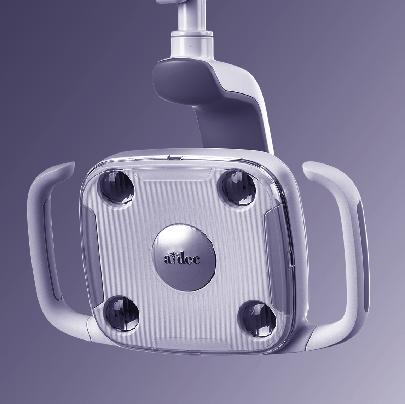
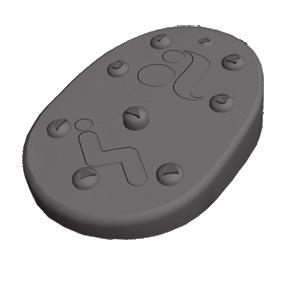
5 Power and System Status Chair Delivery System Master Toggle Status Light Touchpad Power On/Off To power on the Performer dental chair: 1. Verify that the chair is plugged into the mains supply. 2. Flip the master toggle up to turn on the chair. The master toggle is located on the delivery system. The Performer dental chair does not have a power button. When the A-dec logo on the touchpad or the status light on the chair lift arm illuminates, the system is on and ready for use. If the status light blinks, the stop switch has been activated. See Chair Safety Features below for more information. When to Turn Off the Power To save energy, use the master toggle to turn off the power at the end of the work day and during longer periods of non-use. Chair Safety Features Chair Stop Plate Lift Arm A-dec dental chairs and systems include several features designed to improve safety. Activated stop switches may halt the chair or prevent it from moving. To help ensure uninterrupted chair motion: remove any potential obstructions under the chair and attached modules avoid pressing the foot control disc or lever keep handpieces properly seated in their holders If the Chair Stops Unexpectedly Check the actions listed above to correct the condition. If the downward movement of the chair stopped because of an obstruction, use the touchpad or footswitch to raise the chair and remove the obstruction Rev C 3


6 Performer Instructions for Use Chair Footswitch Chair Controls Manual Controls Base Up Back Down Back Up The A-dec touchpad and footswitch control chair movement in the same way. See Touchpad Controls, on page 13, for detailed information about your touchpad controls. Manual Controls Press and hold an arrow button until the chair is in the desired position. The horizontal arrows raise and lower the chair back. The vertical arrows raise and lower the chair base. Base Down Programmable Controls Program Button Programmable Controls Press and release a programmable button to move the chair to a preset position. These buttons are programmed at the factory as follows: Treatment 1 Treatment 2 Icon Position Factory Setting Entry/Exit Positions the chair for patient entry/exit. Entry/Exit X-ray/Rinse Treatment 1 Positions the chair base and back down. Treatment 2 Positions the chair base down and back up. X-ray/Rinse Moves the chair to either x-ray or rinse position. Press again to move the chair to the previous position. 4

7 Footswitch Chair Controls (continued) Treatment 1 Entry/Exit Back Down Program Button Base Down Treatment 2 X-ray/Rinse Base Up Back Up WARNING Ensure that the patient is positioned safely before using the manual or programmable chair controls. Never leave the patient unattended while the chair is in motion. Always take extra care with small children and patients with limited mobility. To stop the chair at any point during programmed movement, push any chair positioning button on the footswitch or touchpad. Reprogram Buttons 0, 1, and 2 To change the factory preset chair positions assigned to the entry/exit and treatment buttons (,, ): 1. Use the manual controls to position the chair as desired. 2. Press and release. One beep indicates that the programming mode is on. 3. Within five seconds, press the chair position button you wish to reprogram (for example, press ). Three beeps confirm that the new setting is programmed into memory. Reprogram X-Ray/Rinse Button The x-ray/rinse button ( ) is preset to move the chair and patient into an upright position for x-rays or cuspidor access. A second press of returns the chair to the previous position. You can reprogram to function in a similar way to the other programmable chair preset buttons. To change its function: 1. Press and hold and at the same time for three seconds. One beep indicates is set as another programmable chair preset button. Three beeps confirm that is configured as the x-ray/rinse factory preset (which toggles between the x-ray/rinse and the previous chair position). 2. If you reprogram as another programmable button and want to assign a different chair position, follow the steps outlined in Reprogram Buttons 0, 1, and 2 above. Chair Back and Base Down Speed Adjustment The chair back and base down speed can be adjusted. Contact your authorized A-dec dealer to reduce or increase the speed Rev C 5

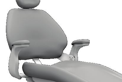
8 Performer Instructions for Use Chair Headrest Positioning The dual-articulating headrest includes several adjustment features that improve your access to the oral cavity and increase patient comfort. Use the glide bar to accommodate a variety of patient heights. Simply pull up or push down on the headrest until it is in the desired position. The gliding headrest cushion provides additional height adjustment. CAUTION If the glide bar has exceeded its maximum recommended working height, a warning line will be visible on the patient s side of the glide bar. Do not use the headrest in a position where this warning line is visible. The locking knob allows you to easily adjust the headrest for a full range of positions. Release the headrest by turning the locking knob counterclockwise, then adjust the headrest for a proper fit. Lock the headrest in the desired position by turning the knob clockwise. 6


9 Headrest Position for Wheelchairs To position the headrest for wheelchairs: 1. Remove the headrest from the dental chair. 2. Rotate the headrest 180 and slide the glide bar into the backrest until it stops. 3. Position the backrest to its full upright position. 4. Position the wheelchair and the dental chair back to back. 5. Move the dental chair up or down, as needed, to adjust the headrest height. 6. Lock the wheelchair wheels. Patient Positioning To properly seat patients in the chair, ask the patient to sit as far back in the seat pocket as possible. This ensures the best alignment with the lumbar support and headrest. For optimal comfort, patients should place their forearms on the armrests or keep their arms comfortably folded on their lap. WARNING Do not allow patients to drop their arms behind the armrests or under the backrest during chair movement Rev C 7

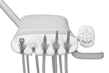
10 Performer Instructions for Use Delivery System Delivery System Control Head Handpiece Drive Air Adjustments 38 Oil Collector 46 Foot Control 10 Handpiece Coolant Adjustments 37 Handpiece Activation and Operation 10 Touchpad 13 8

11 Autoclavable Syringe Water Air 2 Clicks To install the A-dec syringe tip, push the tip in until you feel two clicks. Press both buttons simultaneously for the air/water spray. IMPORTANT For detailed instructions on syringe usage, flow adjustment, and maintenance, see the A-dec Syringes Instructions for Use (p/n ) Rev C 9


12 Performer Instructions for Use Delivery System Handpiece Activation and Operation To activate a handpiece, lift it from the holder. Use the foot control to perform the desired handpiece operation. Accessory/ Chip Blower Button Wet/Dry Toggle Run/ Speed + Control Operation Procedure Disc Foot Control Run a handpiece. Run a handpiece with or without water coolant. Run the optional accessory or chip blower. Operate the intraoral camera. Press on the disc. Push down to increase speed. Move the wet/dry toggle toward the blue dot for wet operation or away from the blue dot for dry operation. Then press on the disc. Press the accessory/chip blower button.* Press on the disc to capture an image.* Lever Foot Control Run a handpiece with water coolant. Move the lever to the left. Move farther to increase speed. Accessory/ Chip Blower Switch Run a handpiece without water coolant. Run the optional accessory or chip blower. Move the lever to the right. Move farther to increase speed. Press the accessory/chip blower switch.* Speed + (wet) Speed + (dry) Operate the intraoral camera. Move the lever to the left or right to capture an image.* * Contact your authorized A-dec dealer for questions about the operation or configuration of your integrated A-dec accessories. NOTE The lever foot control function can be reversed by a technician (change left direction to dry, right direction to wet). For more details, contact your authorized A-dec dealer. For handpiece coolant adjustments, see page
. 2. Slide the stop ring to the desired height groove. 3. Lower the control arm until it stops.")
13 Control Head Positioning Control Arm Stop Ring Performer Delivery System To adjust the control head height: 1. Lift the control arm. NOTE The height adjustment range for the control arm is 5" (127 mm). 2. Slide the stop ring to the desired height groove. 3. Lower the control arm until it stops. Tension Setscrews Control Arm Sleeve Rigid Arm If the control arm is difficult to rotate, or rotates too freely, you should adjust the tension setscrews on the rigid arm. To adjust the control arm tension: 1. Lift the control arm. 2. Note the position of the stop ring and then lift it to the top height groove. 3. Lift the control arm sleeve to reveal the tension setscrews on the rigid arm. 4. Use a 3/32" hex key to loosen or tighten the two tension setscrews the same amount. 5. Lower the control arm sleeve and set the stop ring to its original position. 6. Lower the control arm Rev C 11
. The brake does not restrict side-to-side movement. To adjust the control head height: 1.")
14 Performer Instructions for Use Delivery System Control Head Positioning (continued) A-dec 332/333 Flexarm Brake On systems with a counterbalanced flexarm, an integrated brake maintains the vertical position of the control head (with up to 8 lb [3.6 kg] of additional weight). The brake does not restrict side-to-side movement. To adjust the control head height: 1. Press and hold the button to disengage the brake while you position the control head. 2. Release the button to engage the brake. 12


15 Touchpad Controls The A-dec touchpad and footswitch control chair movement in the same way. See Footswitch Chair Controls, on page 4, for detailed information about your footswitch controls. Basic Touchpad Functions Your system may include a standard or deluxe touchpad. The standard touchpad operates the chair, cuspidor, and dental light functions. The deluxe touchpad adds functions for electric motors and other integrated clinical devices. Both touchpads provide manual and programmable controls. Dental Light Bowl Rinse Cupfill Dental Light Bowl Rinse Cupfill Endodontics/ Electric Motor Controls Manual Chair Controls Programmable Chair Controls Standard Touchpad Deluxe Touchpad Rev C 13


16 Performer Instructions for Use Delivery System Touchpad Controls (continued) Standard Touchpad Deluxe Touchpad Manual Chair Controls Press and hold an arrow button until the chair is in the desired position. The horizontal arrows raise and lower the chair back. The vertical arrows raise and lower the chair base. Chair Back Chair Base Standard Touchpad Deluxe Touchpad Programmable Chair Controls Press and release a programmable button to move the chair to a preset position. These buttons are programmed at the factory as follows: Icon Programmable Chair Buttons WARNING Ensure that the patient is positioned safely before using the manual or programmable chair controls. Never leave the patient unattended while the chair is in motion. Always take extra care with small children and patients with limited mobility. To stop the chair at any point during programmed movement, push any chair positioning button on the footswitch or touchpad. Position Factory Setting Entry/Exit Positions the chair for patient entry/exit. Treatment 1 Positions the chair base and back down. Treatment 2 Positions the chair base down and back partially up (standard touchpad only). X-Ray/Rinse Moves the chair to either x-ray or rinse position. Press again to move the chair to the previous position. Note: Touchpad symbols are proprietary to A-dec Inc. 14
17 Performer Instructions for Use Delivery System Touchpad Controls (continued) Reprogram Entry/Exit, Treatment 1 and 2* Buttons Standard Touchpad To change the factory preset chair positions assigned to the entry/exit and treatment buttons (,, *): Program Button Entry/Exit X-ray/Rinse Treatment 1 Treatment 2 1. Use the manual controls to position the chair as desired. or. One beep indicates that the program2. Press and release ming mode is on. 3. Within five seconds, press the chair position button you wish to reprogram (for example, press ). Three beeps confirm that the new setting is programmed into memory. * Note: The deluxe touchpad does not include a Treatment 2 button. Reprogram X-Ray/Rinse Button Deluxe Touchpad The x-ray/rinse button ( ) is preset to move the chair and patient into an upright position for x-rays or cuspidor access. A second press of returns the chair to the previous position. Entry/Exit Treatment 1 Program Button X-ray/Rinse You can reprogram to function in a similar way to the other programmable chair preset buttons. To change its function: 1. Press and hold or One beep indicates preset button. and at the same time for three seconds. is set as another programmable chair Three beeps confirm that is configured as the x-ray/rinse factory preset (which toggles between the x-ray/rinse and the previous chair position). 2. If you reprogram as another programmable button and want to assign a different chair position, follow the steps outlined in Reprogram Entry/Exit, Treatment 1 and 2* Buttons above Rev C 15

18 Performer Instructions for Use Delivery System Touchpad Controls (continued) Dental Light Indicator (LED) Dental Light Touchpad Controls For detailed information on the touchpad controls for the dental light, see page 31. Dental Light Button Program Button Note: Touchpad symbols are proprietary to A-dec Inc. 16
19 Electric Handpiece Settings (deluxe touchpad only) Standard Mode To activate the electric motor, lift the handpiece from the holder. The touchpad screen displays the previous settings used for that handpiece position. Standard mode provides four factory preset speeds for electric motors: Memory Indicator Standard Mode Display Memory Setting Factory Preset Speed m1 2,000 rpm m2 10,000 rpm Memory Button m3 20,000 rpm m4 36,000 rpm You can reprogram these memory settings with your own specific preset speeds. A total of eight customized settings per handpiece is possible (four in standard mode and four in endodontics mode). To program the handpiece setting: 1. Press or until the rpm setting you want displays on the touchpad screen. 2. Press to save it to memory. One beep sounds. 3. Press to display the m1 through m4 memory settings. When the desired memory setting displays, press. Three beeps confirm the setting Rev C 17
20 Performer Instructions for Use Delivery System Electric Handpiece Settings (deluxe touchpad only) (continued) Memory Indicator Endo Mode Button Endo Mode Display Endodontics (Endo) Mode In addition to handpiece speed adjustments, the endo mode allows you to change a number of settings based on the specific file and desired handpiece behavior. Icons on the touchpad screen reflect the settings. NOTE For more information regarding speed and torque limits for a specific file, consult the file manufacturer. Memory Button To program the handpiece setting: 1. Lift the handpiece from the holder. 2. If the touchpad screen does not display the endo mode, press. 3. To change settings in endo mode, press or. A white reverse video box displays on the touchpad screen. 4. Use the chair positioning buttons to move from setting to setting on the touchpad screen. 5. Use or to change the setting as desired. 6. To set the speed limit, torque limit, or ratio into memory, press. One beep sounds. 7. Press to display the m1 through m4 memory settings. When the desired memory setting displays, press. Three beeps confirm the setting. 18
21 Electric Handpiece Settings (deluxe touchpad only) (continued) Endo Mode Touchpad Screen Icons Icon Setting Description Speed Torque Torque Units Ratio Setpoint for file speed limit. For more information, consult your file manufacturer. Setpoint for file torque limit. For more information, consult your file manufacturer. Toggles between newton centimeters (N cm) and gram centimeters (g cm). Adjusting this setting for one handpiece changes it for all handpiece settings. Note: 1 N cm = 102 g cm. Sets the handpiece ratio. For more information, consult your handpiece manufacturer. Endo Mode Display Ratio Torque Endo Mode Button Speed Forward/ Reverse Indicator Auto Mode Indicator Forward/ Reverse Button Auto Modes Auto Stop Auto Reverse Auto Forward Adjusting this setting for one handpiece changes it for all handpiece settings. The auto mode indicator displays inside of the forward/ reverse indicator. When the file reaches the torque limit, the motor shuts off. When the file reaches the torque limit, the motor stops and reverses direction. When the file reaches the torque limit, the motor stops, reverses 3 turns, then changes back to forward again. Note: If the file is stuck, the auto forward cycle repeats three times before the motor stops. Forward/Reverse Button The forward/reverse button changes the electric motor s direction. The system defaults to the forward position when you return the motor to the holder or turn off the system. In reverse mode, the screen icon flashes continuously Rev C 19

22 Performer Instructions for Use Delivery System Touchpad Help Messages Help Message The deluxe touchpad screen displays help messages for disabled operations. When a help message appears, record the screen message and the function you were performing in case service is required. For complete details on help messages, see the Regulatory Information, Specifications, and Warranty document (p/n ), which is available in the Document Library at Other Handpiece and Accessory Settings See your authorized A-dec dealer to change any of these handpiece and accessory settings, if applicable: Auto-Off Delay determines how long the handpiece light remains on if the foot control is released. The default setting is 5 seconds. On When Selected specifies whether the handpiece light turns on or remains off when the handpiece is removed from the holder. The default setting is on. On in Endo specifies whether the handpiece light turns on or off when the endo mode is selected. The default setting is off, which is recommended to reduce heat and extend bulb life. Ultrasonic Colors for Acteon ultrasonic instruments, specifies whether color-coded tip categories are on or off. The default is on. Voltage Adjustment allows for customized light output voltage for each handpiece position. The default setting is 3.2 VDC. 20
. Pull the holder slightly away from the adjacent one, rotate to the desired position, and then release. To adjust as a complete set, pull from the holder closest to the touchpad.")
 HVE Saliva Ejector The optional Air Vacuum System (AVS) generates a vacuum using an air supply at 70 psi (483 kpa) minimum when a central vacuum system is not")
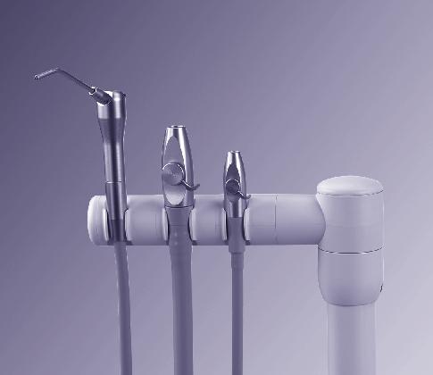
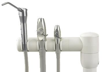
23 Assistant s Instrumentation Instrument Holders 1 Pull Out The instrument holders rotate independently to allow customized positioning for each instrument (with the auto-air holder option, the holders rotate only as a set). Pull the holder slightly away from the adjacent one, rotate to the desired position, and then release. To adjust as a complete set, pull from the holder closest to the touchpad. CAUTION Twisting the holder without pulling it away from the adjacent one will damage the mechanism. 2 Rotate Air Vacuum System (AVS) HVE Saliva Ejector The optional Air Vacuum System (AVS) generates a vacuum using an air supply at 70 psi (483 kpa) minimum when a central vacuum system is not available. It also separates moisture and air that flows through the system and discharges them through a drain and air outlet. On AVS-equipped systems, the assistant s instrumentation includes a feature called auto-air switching. Auto-air switching activates the air vacuum generator when the instruments are removed from the holder. Lift the instrument and open the valve for normal operation. Return the instrument to its holder to turn off the vacuum Rev C 21

24 Performer Instructions for Use Assistant s Instrumentation HVE and Saliva Ejector Right/Left Conversion You can easily convert the A-dec HVE and saliva ejector for right- or left-handed operation. Push the control valve out of the HVE or saliva ejector valve body by pressing on the small diameter side. While holding the HVE or saliva ejector in its original position, rotate the control valve 180 and push it back into place. NOTE Be sure to reinstall the valve on the same side of the valve body. Otherwise, the HVE or saliva ejector will not operate properly. 22
25 A-dec HVE/Saliva Ejector Valve Body Assembly Asepsis NOTE Vacuum-lines should be cleaned at the end of each day by evacuating a detergent or water-based detergentdisinfectant through the system. If you use barrier film to protect the main body of the A-dec HVE and saliva ejector, replace the barrier film after each patient. Clean and disinfect these instruments at the end of each day or after each patient if the barrier film has been compromised. If you do not use barrier film, or if you perform oral surgery, always clean and disinfect these instruments after each patient. Disinfection To disinfect the A-dec HVE and saliva ejector valve body assembly without disconnection from the vacuum system: 1. Remove the vacuum tip from the HVE or saliva ejector. 2. Disinfect the valve body assembly by using an intermediate-level disinfectant according to instructions for the disinfectant; A-dec recommends a phenolic (dual) water-based disinfectant. 3. Follow the manufacturer s instructions for disinfectant contact time. 4. Operate the HVE and the saliva ejector valves several times to verify that they rotate smoothly Rev C 23

26 Performer Instructions for Use Assistant s Instrumentation A-dec HVE/Saliva Ejector Valve Body Assembly Asepsis (continued) NOTE A-dec valve body assemblies are heat tolerant for sterilization. Users may sterilize at their discretion. Routine Maintenance and Sterilization To routinely maintain and sterilize the A-dec HVE and saliva ejector when disconnected from the vacuum system (frequency determined by the user): 1. Turn off the vacuum or open the control valve before disconnecting the HVE or saliva ejector. 2. Remove the vacuum tip from the HVE or saliva ejector. Discard disposable vacuum tips. 3. Remove the HVE or saliva ejector valve body assembly from the vacuum line by pulling it away from the tubing at the tailpiece. 4. Disassemble the valve body assembly by pushing the control valve out of the HVE or saliva ejector valve body. 5. Inspect the O-rings. Remove and discard if damaged. 6. Clean undamaged O-rings with a soft brush and a health authority approved detergent. O-rings may be cleaned in place or removed and cleaned at the discretion of the user. 7. Clean all exterior and interior surfaces of the valve body and control valve using a health authority approved detergent and the brushes provided with the product (or equivalent). Lumens or channels of the valve body must be cleaned with a brush of the proper length and diameter. The brush must be long enough to extend through the lumen. 8. Rinse thoroughly with water. 24
27 A-dec HVE/Saliva Ejector Valve Body Assembly Asepsis (continued) 9. Process the disassembled valve body assembly components through a washer-disinfector. If a washer-disinfector is unavailable, valve body assembly components must be manually disinfected using a health authority approved disinfectant. 10. Allow the components to dry completely. 11. Sterilize the valve body assembly components at C ( F) for 4 minutes in a pre-vacuum sterilizer or at C ( F) for 6 minutes in a gravity displacement sterilizer. 12. Prior to use, replace O-rings as needed, lubricate O-rings with A dec silicone lubricant, and reassemble the valve body assembly. CAUTION Use only silicone lubricant when lubricating black O-rings. Petroleum-based products will cause permanent damage to the O-rings. 13. Reinstall the valve body assembly on the tubing tailpiece. 14. Operate the HVE and the saliva ejector control valves several times to verify that they rotate smoothly Rev C 25

28 Performer Instructions for Use Assistant s Instrumentation A-dec HVE/Saliva Ejector Tip Asepsis NOTE Select tips that are compatible with your HVE and saliva ejector openings. See HVE and Saliva Ejector Openings for Tips on page 50 for specifications. Disposable Tips Replace disposable HVE and saliva ejector tips after each use. CAUTION Disposable HVE and saliva ejector tips are not sterilizable and should not be reused. Sterilizable Tips Heat sterilize stainless steel HVE tips after each use. To clean and sterilize a stainless steel HVE tip: 1. Remove the tip from the HVE. 2. Clean and rinse the tip using a mild detergent and water, then allow the tip to dry completely. 3. Sterilize the tip at C ( F) for 4 minutes in a prevacuum sterilizer or 6 minutes in a gravity displacement sterilizer. 26

29 Dürr HVE and Saliva Ejector Asepsis Saliva Ejector HVE If you use barrier film to protect the main body of the Dürr HVE and saliva ejector, clean and sterilize these instruments weekly, or more frequently as needed. If you do not use barrier film, or if you perform oral surgery, clean and sterilize these instruments after each patient. CAUTION Disposable HVE and saliva ejector tips are not sterilizable and should not be reused. To clean and sterilize the Dürr HVE and saliva ejector: 1. Turn off the vacuum. 2. Remove the tip from the HVE or saliva ejector. 3. Remove the HVE or saliva ejector valve body by pulling it away from the tubing at the tailpiece. 4. Clean and rinse the valve body using a mild detergent, water, and a brush. 5. Allow the instruments to dry completely. 6. Heat sterilize the instruments using a steam autoclave for at least 6 minutes at a dwell temperature of 134 ºC (273 ºF). 7. Apply a light coat of petroleum-based lubricant on the red O-ring seal. CAUTION Use only petroleum-based lubricant on red O-rings in Dürr instrumentation. Silicone lubricants can damage the material. 8. Reinstall the valve body on the tubing tailpiece. 9. Verify that the HVE and the saliva ejector operate and rotate smoothly Rev C 27

, barriers, disinfectant, and sterilization to minimize exposure hazard.")
30 Performer Instructions for Use Assistant s Instrumentation Solids Collector The solids collector helps prevent solids from entering the central vacuum system. To ensure proper suction from the central vacuum and maintain proper treatment room asepsis, discard and replace the solids collector screen at least twice a week. BIOHAZARD Biohazard from dental equipment can result in life threating disease to patients and staff. Use appropriate precautions including PPE (Personal Protective Equipment), barriers, disinfectant, and sterilization to minimize exposure hazard. TIP To obtain replacement solids collector screens, contact your authorized A-dec dealer and reference Pinnacle p/n To replace the solids collector screen: 1. Turn off the vacuum or open the HVE control valve. 2. Remove the solids collector cap. 3. Remove the solids collector screen. 4. Discard the screen according to your local regulations. 28


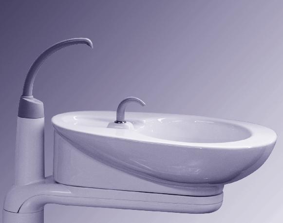
31 Cuspidor Cupfill Spout Bowl Rinse Spout Bowl Rinse Button Cupfill Button The cuspidor cupfill and bowl rinse functions can be controlled from the cuspidor or the touchpad. Cuspidor Controls Press and hold the cupfill button on the cuspidor for the desired amount of water. Release the button to stop the flow. Press the bowl rinse button on the cuspidor once for a 15-second rinse. For continuous rinse, hold the button down. When you release the button, the water will continue to flow for 15 additional seconds. Touchpad Controls You can also use the buttons on the touchpad to operate and program bowl rinse and cupfill functions: Button Description and Action Support Center Bowl Screen Cupfill Button: Press and release the cupfill button for a timed operation. The factory preset is a 2.5 second fill. Press and hold the cupfill button for manual operation. Bowl Rinse Button: Press the bowl rinse button for a timed operation. The factory preset is a 30 second rinse. Press and hold the bowl rinse button for manual operation. Press the bowl rinse button twice in less than two seconds to activate the continuous operation mode. Press the button once to end the continuous operation mode Rev C 29


32 Performer Instructions for Use Cuspidor Programming Cuspidor Buttons Program Button To reprogram the timed cupfill or bowl rinse functions: 1. Press on the touchpad or press and hold both the cupfill and bowl rinse buttons on the cuspidor. Release them when you hear one beep. 2. Press and hold the cupfill or bowl rinse button for the desired time. 3. Release the button. Three beeps confirm that the program has changed. Bowl Rinse Cupfill Bowl Rinse Flow Adjustment Pinch Valve Adjustments to the cuspidor bowl rinse flow are made inside the support center. To make an adjustment: 1. Carefully pull the bottom edge of the cover out and remove the cover. 2. With the cuspidor bowl rinse on, tighten or loosen the pinch valve to adjust the flow. 3. For the best rinsing action, adjust the flow pattern by rotating the bowl rinse spout. 30

33 Dental Light Touchpad Controls Standard Touchpad Deluxe Touchpad Dental Light Indicator (LED) Dental Light Program Button Dental Light If your system includes a dental light that supports touchpad control, the following functions are available from the touchpad. Dental Light Button To turn on the light, press and release the light button. To turn off the light, press and briefly hold the light button. To change the intensity mode, press and release the light button to toggle between intensity settings. Dental Light Auto On/Off Feature The auto on/off feature turns on the A-dec light once the chair reaches a preset treatment position. When you press or, the dental light turns off and the chair moves to that preset position. To disable the auto on/off feature, press and hold the program button ( or ) and at the same time for three seconds until you hear one beep. To enable the auto on/off feature, press and hold or and at the same time for three seconds until you hear three beeps. For more information about dental light functions, see your dental light Instructions for Use. Program Button Note: Touchpad symbols are proprietary to A-dec Inc Rev C 31

34 Performer Instructions for Use Mechanical Adjustments Mechanical Adjustments Headrest Glide Bar 33 Pivot Point Tension 34 Delivery System 34 32
35 Chair Adjustments Headrest Positioning The headrest includes several adjustment features that improve your access to the oral cavity and increase patient comfort. Use the glide bar to accommodate a variety of patient heights. Simply pull up or push down on the headrest until it is in the desired position. The gliding headrest cushion provides additional height adjustment. CAUTION If the glide bar has exceeded its maximum recommended working height, a warning line will be visible on the patient s side of the glide bar. Do not use the headrest in a position where this warning line is visible. The locking knob allows you to easily adjust the headrest for a full range of positions. Release the headrest by turning the locking knob counterclockwise, then adjust the headrest for a proper fit. Lock the headrest in the desired position by turning the knob clockwise. Headrest Glide Bar Tension Adjustment If the headrest drifts downward, or if it is difficult to move up or down, the glide bar tension needs adjustment. To adjust the tension, use a 1/8'' hex key. Turn the tension adjustment screw clockwise to increase friction or counterclockwise to decrease friction. Decrease Increase Rev C 33

36 Performer Instructions for Use Mechanical Adjustments Delivery System Adjustments Pivot Point Tension Adjustments If the delivery system drifts, you can adjust the tension on the delivery system rigid arm. Adjust the Back-Mount Delivery System or Dental Light Tension 1. Use a 5/32" hex key to remove the four screws that secure the seat upholstery to the chair casting and remove the upholstery. 2. Lower the seat back all the way down. This provides access to the back-mount tension adjustment screw. 34

37 Adjust the Back-Mount Delivery System or Dental Light Tension (continued) 3. Use a 1/4" hex key to adjust the tension of the screw. Adjust the screw until the arm rotates easily but does not drift. 4. Reinstall the seat upholstery and secure it with the four screws removed earlier. Back-Mount Tension Adjustment Screw Rev C 35

38 Performer Instructions for Use Mechanical Adjustments Adjust the Front-Mount Delivery System or Dental Light Tension The front-mount tension adjustment is accessed below the seat upholstery at the front of the chair. 1. Use a 1/4" hex key to adjust the tension of the screw. Adjust the screw until the arm rotates easily but does not drift. 36


39 Handpiece Coolant Adjustments CAUTION When performing this procedure, do not attempt to completely shut off the water or air flow. The adjustment knobs are not designed to completely shut off flow and can damage the control block if you apply too much force. Air Coolant Adjustment Knob Water Coolant Adjustment Knobs The air coolant knob on your delivery system simultaneously adjusts air flow to all handpiece positions. Each water coolant knob adjusts water flow to a single position. Use the following process to adjust for the desired handpiece coolant atomization: 1. Insert a bur into each handpiece you are adjusting. 2. Turn the air coolant adjustment knob clockwise until coolant flow stops. 3. Lift the handpiece from the holder, or pull the whip forward, and do one of the following: On a disc foot control: flip the wet/dry toggle to water (toward the blue dot) and press the disc all the way down. On a lever foot control: move the lever all the way to the left. 4. Locate the water coolant adjustment knob for the handpiece position you are adjusting and turn it clockwise until coolant flow stops. 5. Slowly turn the water coolant adjustment knob counterclockwise until water droplets are expelled from every water port on the handpiece head. Return the handpiece to the holder. 6. Repeat steps 3 through 5 for each handpiece. 7. To set the air coolant for the system, lift a handpiece from the holder or pull the whip forward. 8. Turn the air coolant adjustment knob counterclockwise until you achieve the desired atomization at the cutting surface of the bur. Disc Foot Control Wet/Dry Toggle Lever Foot Control CAUTION Do not continue turning the air coolant adjustment knob counterclockwise after the air coolant stops increasing. The stem may come out of the control block. 9. If you require more water coolant, increase the water output in step 5 as needed Rev C 37


40 Performer Instructions for Use Mechanical Adjustments Drive Air Message Handpiece Drive Air Adjustments You can check drive air pressure on the deluxe touchpad screen by pressing and at the same time. For systems with a standard touchpad, and for the most accurate drive air measurement, use a handpiece pressure gauge (A-dec p/n ) attached to the handpiece tubing. To adjust the drive air pressure for each handpiece: Cover Screws 1. Remove the control head cover screws. Remove the cover and locate the drive air pressure controls inside. 2. Lift the handpiece from the holder or pull the whip forward. 3. Do one of the following: On a disc foot control: flip the wet/dry toggle to dry, and press the disc all the way down. On a lever foot control: move the lever all the way to the right. 4. With the handpiece running, check the deluxe touchpad readout or handpiece pressure gauge. 5. Adjust the handpiece drive air pressure to meet the manufacturer s specifications. Turn the control stem clockwise to decrease flow and counterclockwise to increase flow. CAUTION See your handpiece documentation for the drive air pressure specification. Exceeding manufacturer s recommendations increases the risk of damage and may significantly decrease the life of your handpiece components. Wet/Dry Toggle Disc Foot Control Lever Foot Control 38


41 Rotational Adjustments Control Head If the control head is too loose or difficult to rotate, use a 5/32" hex key to adjust the tension screw under the control head. Hex Key Tray Holder If the tray holder rotation is too tight or too loose, use a 9/64" hex key to adjust the tension: 1. Insert the hex key through the mounting bracket. If necessary, rotate the holder or arm until the key slides completely into the mounting bracket. 2. While holding the bracket stationary, turn the tray holder clockwise to increase the tension or counterclockwise to reduce the tension Rev C 39


42 Performer Instructions for Use Mechanical Adjustments Vertical Adjustments Flexarm End Cap Spring Tension Rod Button Head Screw 5/16" Socket and Ratchet On systems that have a counterbalanced flexarm: If the control head falls or rises rapidly when you flip the master toggle to the off position, complete these steps to adjust the flexarm spring tension: 1. Flip the master toggle to the on position. 2. Load the control head for normal use, attaching handpieces and placing a tray on the tray holder. 3. Position the control head so the flexarm is level. 4. Use a 1/8" hex key to loosen the button head screw that secures the end cap farthest from the control head, then pull the cap straight out. 5. Flip the master toggle to the off position. 6. Use a 5/16" socket and ratchet to adjust the flexarm spring tension rod until the control head rises gradually when you flip the Master toggle to the off position. If the control head rises rapidly, turn the rod counterclockwise. If the control head falls, turn the rod clockwise. 40


43 Dental Light Adjustments Refer to the Instructions for Use that shipped with your light for detailed adjustment instructions Rev C 41


44 Performer Instructions for Use Cleaning and Maintenance Cleaning and Maintenance Barrier Protection NOTE For proper use and disposal of barriers, see the instructions provided by the barrier manufacturer. Waterline Maintenance A-dec recommends barrier protection for all applicable touch and transfer surfaces. Touch surfaces are areas that come into contact with hands and become potential cross-contamination points during dental procedures. Transfer surfaces are areas that come into contact with instruments and other inanimate objects. In the USA, barriers must be produced under the Current Good Manufacturing Practice (CGMP) as specified by the U.S. Food and Drug Administration (USFDA). For regions outside the USA, refer to the medical device regulations specific to your location. IMPORTANT For recommendations on cleaning and chemical disinfection of touch and transfer surfaces (where barrier protection is not applicable or when barriers are compromised), please see the A-dec Equipment Asepsis Guide (p/n ). A-dec recommends that you perform a shock treatment on the dental unit waterlines before you use the system for the first time. For on-going waterline maintenance, A-dec recommends a three-part protocol: continuous use of A-dec ICX waterline treatment tablets, regular dental unit water monitoring, and shock treatment. Self-Contained Water Bottle IMPORTANT For complete details on how to maintain good water quality in your system, see the instructions for use provided with ICX and your self-contained water bottle: A-dec ICX... p/n A-dec Self-Contained Water System... p/n Waterline Maintenance Guide... p/n
45 Upholstery CAUTION Do not use household bleach (sodium hypochlorite) or other products containing chlorine, isopropyl alcohol (greater than 25 percent by volume), or hydrogen peroxide to clean or disinfect the upholstery. It can cause rapid deterioration and damage the product. To preserve the quality of your A-dec upholstery, use barrier covers instead of relying on chemicals. Barriers significantly extend the life of the upholstery and will help to preserve its luxurious look and soft feel. To clean the upholstery, use a solution of mild detergent and water. Use surface disinfectants only when the barriers have been compromised or there is visible spatter on the upholstery. For more information, see the Upholstery Maintenance Guide (p/n ), which is available in the Document Library at Rev C 43

46 Performer Instructions for Use Cleaning and Maintenance Self Contained Water System The 2-liter self-contained water bottle supplies water to handpieces, syringes, and the cuspidor cupfill. For proper installation: 1. To remove the bottle, turn off the Master toggle, and rotate the bottle clockwise. 2. Empty any remaining water from the bottle. WARNING Avoid touching the A-dec ICX waterline treatment tablet with unprotected skin. For more details, please refer to the instructions for use provided with the ICX tablets (p/n ). 3. Following the ICX instructions for use, place an ICX tablet in the bottle and fill it with water. 4. Insert the bottle so the A-dec logo is in front, facing away from the chair.* CAUTION Do not overtighten the water bottle or you may damage the components. WARNING Use only A-dec self-contained water bottles. Do not use other bottles, including glass or plastic beverage bottles. Do not use damaged bottles. These can pose a serious safety hazard while pressurized. A-dec plastic water bottles cannot withstand heat sterilization. Attempting to do so will damage the bottle and your sterilizer. 5. Rotate the bottle to the counterclockwise 1-1/2 turns. Do not overtighten. 6. Turn on the master toggle. A pressurization sound may be heard up to 2 minutes after the system is turned on. * For left-handed configurations, the A-dec logo should face toward the chair. 44
47 Self Contained Water System (continued) CAUTION Use caution when using the self-contained water system with accessories that require an uninterrupted water supply (e.g., scalers), as these could get damaged without a continuous water source. Do not use saline solutions, mouth rinses, or any chemical solutions not specified in this guide in your A-dec self-contained water system. These may damage the system components and cause your dental unit to fail. How to Choose Treatment Water The correct water to use in the A-dec self-contained water system depends on the quality of your municipal water. It s important to choose a source that consistently provides good water quality. For guidance, refer to the regulations specific to your location. Tap Water If you have confidence in the quality of your municipal water supply, consider using tap water in your self contained water bottle. Bottled Water If you have concerns about the quality of your municipal water supply, use bottled water from a commercial source. Softened Water In areas with hard water, greater than 200 mg/l as calcium carbonate (11.7 grains per gallon, 2.0 mmol/l), A-dec recommends the use of a water softener to prevent the buildup of mineral deposits that may impact the functionality of your delivery system Rev C 45


48 Performer Instructions for Use Cleaning and Maintenance Cleaning the Handpiece Tubing Use the flush toggle to move a high volume of water through the handpiece tubing. To flush the tubing after each patient: 1. Disconnect the handpieces. 2. Hold all of the handpiece tubing that uses water coolant over a sink, cuspidor bowl, or basin. 3. Hold the flush toggle down for seconds. NOTE Discharge all tubing air and water lines for seconds after each patient. Flush Toggle IMPORTANT For recommendations on cleaning and chemical disinfection of touch and transfer surfaces (where barrier protection is not applicable or when barriers are compromised), please see the A-dec Equipment Asepsis Guide (p/n ). Servicing the Oil Collector Service the oil collector on the delivery system once a week for normal usage and more often for heavier use. To service: 1. Unsnap the oil collector cover from the control head and discard the old gauze. Do not remove the foam muffler. 2. Fold a new gauze pad (2" x 2" [51 mm x 51 mm]) into quarters and place it inside the cover. 3. Snap the oil collector cover closed. 46


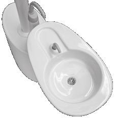
49 Cleaning the Cuspidor Bowl The contoured spouts and smooth bowl of the cuspidor provide for quick and easy cleaning. Remember to empty and clean the bowl screen every time you clean the cuspidor. CAUTION Do not remove the spouts when cleaning the cuspidor. This will help prevent cleaning solutions from damaging the equipment and contaminating the cupfill water. CAUTION Do not empty the solids collector or bowl screens into your cuspidor. Doing so could plug the cuspidor drain. After cleaning, always install the bowl screen in the cuspidor bowl drain to prevent debris from plugging the drain. Gravity Drain Cleaning Maintenance Parts At the end of each day, flush the cuspidor to remove debris from the flexible drain tubing. If the cuspidor is not flushed regularly, debris may build up and impair draining. To flush the cuspidor, run the bowl rinse for about 60 seconds. For replacement cuspidor bowl screens, order p/n Bowl Screen Rev C 47
50 P Performer Instructions for Use Cleaning and Maintenance Dental Light Shield Maintenance Dental Light Bulb Replacement Dental Light Circuit Breaker Location Refer to the Instructions for Use that came with your dental light for information on dental light shield maintenance. Refer to the Instructions for Use that came with your dental light for information on replacing the dental light bulb. Under abnormal conditions, the dental light circuit breaker interrupts the flow of electricity. If the circuit breaker should trip, reset it by pushing the circuit breaker. The circuit breaker for your dental light is located on the power supply. 10 AM 10 AM P 10 AM P 10 AM P 10 AM P 48

51 Utilities and Shutoff Valves Optional 2" Data Conduit Electrical Box Filter Housing O-Ring CAUTION When removing or replacing covers, take care not to damage any wiring or tubing. Verify that the covers are secure after replacing them. Filter Air Vacuum Beveled Edge Drain Water Manual Shutoff Valve The utilities for A-dec chair-mounted delivery systems are located in the contoured floor box under your chair. To access, lift the cover up and off the floor box frame. The manual shutoff valves control the air and water to the system. To prevent leaks, leave these valves fully open (turned counterclockwise), except when your system is being serviced. Air and water pass through separate filters before entering the regulators. Replace these filters when they become clogged and restrict flow. To check for a clogged water filter: 1. Turn on the master toggle. 2. While watching the cuspidor, press the bowl rinse button. If the bowl rinse water pressure fades or if the water flow stops, replace the water filter. To replace the filter: 1. Turn off the master toggle and close the shutoff valves (turn clockwise). 2. Bleed the system of air and water pressure by operating the syringe buttons until air and water no longer flow. 3. Using a standard screwdriver, remove the filter housing from the water pre-regulator assembly and remove the filter. 4. Replace the filter if it is clogged or discolored. Install the filter with the beveled edge facing the manifold. CAUTION To ensure proper operation, install the filter with the beveled edge facing the manifold. Pre-Regulator Assembly 5. Open the shutoff valves, turn on the master toggle, and operate the bowl rinse to remove air from the waterline Rev C 49
Assistant s Instrumentation T
 Instructions for Use Assistant s Instrumentation 85.2610.00 T Copyright 2015 A-dec Inc. All rights reserved. A-dec Inc. makes no warranty of any kind with regard to this material, including, but not limited
A-dec 300 Delivery Systems
 Instructions for Use A-dec 300 Delivery Systems Models 332, 333, 334, 335, and 336 A-dec 300 Delivery Systems Instructions for Use Copyright 2017 A-dec Inc. All rights reserved. A-dec Inc. makes no warranty
A-dec 500 Delivery Systems
 Instructions for Use A-dec 500 Delivery Systems Models 532, 533, and 542 A-dec 500 Delivery Systems Instructions for Use Copyright 2016 A-dec Inc. All rights reserved. A-dec Inc. makes no warranty of any
Instructions for Use. A-dec 4631 Duo Delivery System and A-dec 4635 Assistant s
 Instructions for Use A-dec 4631 Duo Delivery System and A-dec 4635 Assistant s 85.2643.00 Copyright 2016 A-dec Inc. All rights reserved. A-dec Inc. makes no warranty of any kind with regard to this material,
A-dec 300 LED Dental Light
 Instructions for Use A-dec 300 LED Dental Light Models 371L 378L A-dec 300 LED Dental Light Instructions for Use Copyright 2018 A-dec Inc. All rights reserved. A-dec Inc. makes no warranty of any kind
A-dec 200 Service Guide Contents
 A-dec 200 Service Guide 1 A-dec 200 Service Guide Contents Overview... 3 Get Support... 3 International Customer Service... 3 Other Sources of Information... 3 Electronic Documentation... 3 A-dec 200 System
A-dec 541 Delivery System and 545 Assistant s Instrumentation
 Installation Guide A-dec 541 Delivery System and 545 Assistant s Instrumentation Before You Begin A-dec 545 12 O Clock Assistant s Instrumentation The instructions are the same for installing both the
A-dec O Clock Delivery System
 Installation Guide A-dec 500 12 O Clock Delivery System Before You Begin A-dec 545 12 O Clock Assistant s Instrumentation Before starting the installation: Check with local building and code authorities
Instructions for Use. Cascade 2615 Cart
 Instructions for Use Cascade 2615 Cart 85.0664.00 Copyright 2016 A-dec Inc. All rights reserved. A-dec Inc. makes no warranty of any kind with regard to this material, including, but not limited to, the
INSTRUCTIONS FOR USE. A-dec 311 Dental Chair
 INSTRUCTIONS FOR USE A-dec 311 Dental Chair A-DEC 311 D ENTAL CHAIR I NSTRUCTIONS FOR USE Copyright 2008 A-dec Inc. All rights reserved. A-dec Inc. makes no warranty of any kind with regard to this material,
DECADE 1021 SOLO CHAIR
 Owner's Guide DECADE 1021 SOLO CHAIR 85-2626-00 Warranty A-dec warrants its products against defects in material or workmanship for one year from time of delivery (except for handpieces which have a warranty
Pre-Installation Guide Performer
 Pre-Installation Guide Performer Contents Structural Requirements... 1 Dental Patient Chair Interface Requirement... 1 Utility Requirements... 1 Utility Specifications... 2 Electrical Ratings... 3 Shipping
A-dec 542 Side Delivery System I NSTALLATION GUIDE
 -dec 542 Side Delivery System I NSTLLTION GUIDE This document contains installation instructions for the -dec 542 side delivery system. NOTE Depending on your equipment configuration, some steps in the
The A-dec Difference.
 A-dec 200 The A-dec Difference. The best way to discover what dentists need in a chair and delivery system is to ask. We did. And the A-dec 200 design reflects the way dental teams work, and purposefully
The A-dec Difference Built for Life
 A-dec 300 The A-dec Difference Built for Life At A-dec, no detail is too small, right down to the bolts that go into our products. That s why we manufacture a large majority of our finished dental equipment
The A-dec Difference Built for Life
 A-dec 300 The A-dec Difference Built for Life At A-dec, no detail is too small, right down to the bolts that go into our products. That s why we manufacture a large majority of our finished dental equipment
The A-dec Difference Built for Life
 A-dec 300 The A-dec Difference Built for Life At A-dec, no detail is too small, right down to the bolts that go into our products. That s why we manufacture a large majority of our finished dental equipment
A-dec 351 Assistant s Instrumentation on an A-dec 311/411/511 Dental Chair INSTALLATION GUIDE
 A-dec 351 Assistant s Instrumentation on an A-dec 311/411/511 Dental Chair INSTALLATION GUIDE Contents Before You Begin.......... 2 Install the Rigid Arm....... 3 Connect the Electrical Wires and Data
A-dec 371L or 571L Dental Light on an A-dec 361, 362, or 363 Support Center INSTALLATION GUIDE
 A-dec 37L or 57L Dental Light on an A-dec 36, 36, or 363 Support Center INSTALLATION GUIDE 37L 57L Before You Begin WARNING Failure to turn off or disconnect the power before you begin this procedure can
Asepsis 21 Delivery Unit
 INSTALLATION INSTRUCTIONS for the Console Mounted TM Asepsis 21 Delivery Unit SECTION I - REQUIREMENTS 1. PHYSICAL REQUIREMENTS... 1 2. ELECTRICAL REQUIREMENTS... 1 3. WATER SUPPLY REQUIREMENTS... 1 4.
Instructions for Use. A-dec EA-30. Electric Motor System
 Instructions for Use A-dec EA-30 Electric Motor System Copyright 2012 A-dec Inc. All rights reserved. A-dec Inc. makes no warranty of any kind with regard to this material, including, but not limited to,
A-dec Dental Lights on an A-dec 300 Base Mount Post INSTALLATION GUIDE
 A-dec Dental Lights on an A-dec 300 Base Mount Post INSTALLATION GUIDE Before You Begin Turn off the power to the system before you begin the installation. DANGER Failure to turn off the power before you
DECADE 1021 VAC BACK CHAIR
 Owner's Guide DECADE 1021 VAC BACK CHAIR 85-2625-00 Warranty A-dec warrants its products against defects in material or workmanship for one year from time of delivery (except for handpieces which have
A-dec Stools. A-dec 1601 Doctor's Stool A-dec 1621, 1622, and 1626 Assistant's Stools
 Instructions for Use -dec Stools -dec 1601 Doctor's Stool -dec 1621, 1622, and 1626 ssistant's Stools -DEC STOOLS I NSTRUCTIONS FOR USE Copyright 2009 -dec Inc. ll rights reserved. -dec Inc. makes no warranty
Owner s Guide PERFORMER III
 Owner s Guide PERFORMER III 85.2638.00 R ALPHABETICAL EQUIVALENT TO THE NUMERAL OF THE MONTH MANUFACTURED A B C D E F G H I J K L January February March April May June July August September October November
CASCADE CHAIR-MOUNTED HANDPIECE CONTROL WITH CASCADE MASTER SERIES TOUCH PAD
 R A-DEC INC. 2601 CRESTVIEW DRIVE POST OFFICE BOX 111 NEWBERG, OREGON 97132 USA TELEPHONE (503)-538-9471 DESIGNATED E.U. REPRESENTATIVE: A-DEC DENTAL U.K., LTD. AUSTIN HOUSE 11 LIBERTY WAY ATTLEBOROUGH
Owner's Guide CASCADE 2671 DUO CART AND CASCADE 3171 DUO WALL-MOUNT
 Owner's Guide CASCADE 2671 DUO CART AND CASCADE 3171 DUO WALL-MOUNT 85.2641.00 ALPHABETICAL EQUIVALENT TO THE NUMERAL OF THE MONTH MANUFACTURED A B C D E F G H I J K L January February March April May
Cascade 3072 Delivery System INSTALLATION GUIDE
 Cascade 3072 Delivery System INSTALLATION GUIDE Getting Started Figure 1. Cascade 3072 Delivery System See the section below that applies to your unit. the Wall............. 1 Preference II 5512 Cabinet......................................
A-dec 336 Delivery System on an A-dec 411 or 511 Dental Chair INSTALLATION GUIDE
 A-dec 6 Delivery System on an A-dec 4 or 5 Dental Chair INSTALLATION GUIDE Before You Install the 6 Delivery System Install the Rigid Arm A-dec 4 Dental Chair: Follow the instructions for installing the
A-dec 311, 411, and 511 Dental Chairs Service Reference
 A-dec,, and Dental Chairs Service Reference Copyright Regulatory Information Contents 0 A-dec Inc. All rights reserved. A-dec Inc. makes no warranty of any kind with regard to this material, including,
Service Guide A-DEC SIMULATORS. Mobile (4810) and Stationary (4820)
 and Stationary (4820)") Service Guide A-DEC SIMULATORS Mobile (4810) and Stationary (4820) A-DEC M OBILE AND STATIONARY SIMULATORS 4810 AND 4820 S ERVICE GUIDE Copyright 2015 A-dec Inc. All rights reserved. 2601 Crestview Drive,
Service Guide A-DEC SIMULATORS Mobile (4810) and Stationary (4820) A-DEC M OBILE AND STATIONARY SIMULATORS 4810 AND 4820 S ERVICE GUIDE Copyright 2015 A-dec Inc. All rights reserved. 2601 Crestview Drive,
Installation Operation Maintenance Troubleshooting Version 1, Oct/09. Palm Beach
 Installation Operation Maintenance Troubleshooting Version 1, Oct/09 1655 Palm Beach Congratulations! All of us at Summit Dental Systems want you to know that your 1655 Palm Beach Cuspidor has been built
Radius Cuspidor (for Cascade 1040 or Decade 1011/1021 Chairs)
") INSTALLATION INSTRUCTIONS Radius Cuspidor (for Cascade 1040 or Decade 1011/1021 Chairs) You Will Need: Hex key set Level Large flat head screwdriver Pliers 1/2" and 9/16" wrench Cutters Before Beginning
INSTALLATION INSTRUCTIONS Radius Cuspidor (for Cascade 1040 or Decade 1011/1021 Chairs) You Will Need: Hex key set Level Large flat head screwdriver Pliers 1/2" and 9/16" wrench Cutters Before Beginning
The A-dec Difference 5 YEAR WARRANTY. You can count on A-dec products to work consistently so you can stay focused on what matters most: the patient.
 A-dec 400 The A-dec Difference You can count on A-dec products to work consistently so you can stay focused on what matters most: the patient. Eliminate downtime. Keep ownership costs low. Expect lasting
OPERATION and MAINTENANCE INSTRUCTION MANUAL. ADU-12DCE Task Force Deluxe Portable Pneumatic Dental System
 OPERATION and MAINTENANCE INSTRUCTION MANUAL ADU-12DCE Task Force Deluxe Portable Pneumatic Dental System TABLE OF CONTENTS: Package Contents....................i Introduction.........................1
X-Calibur BDS Delivery Systems
 X-Calibur BDS Delivery Systems Table of Contents Page Customer Unit Identification Record 1 General Unit Anatomy 2 Types Of Units 3 Description of Components 5 Control Head Features 5 Cuspidor Features
Legendary A-dec Reliability
 A-dec 500 Legendary A-dec Reliability You can count on A-dec equipment to work when you do. Innovative Engineering Legendary A-dec reliability starts with our design philosophy create innovative, feature-rich
The A-dec Difference. You can count on A-dec products to work consistently so you can stay focused on what matters most: the patient.
 A-dec 400 The A-dec Difference You can count on A-dec products to work consistently so you can stay focused on what matters most: the patient. Eliminate downtime. Keep ownership costs low. Expect lasting
1416 Cabinet Unit. Installation Operation Maintenance Troubleshooting Version Dec/17
 Installation Operation Maintenance Troubleshooting Version Dec/17 1416 Cabinet Unit Page 1 of 16 Table of Contents Important Information... 3 Weight & Dimensions... 4 Operator s Instructions... 5 Flow
Simplicity Chair Mounted Unit
 Simplicity Chair Mounted Unit Installation, Operation & Care Manual DentalEZ MAKES YOUR PRACTICE PERFECT Table of Contents Section I Introduction Specifications... 3 Classifications... 3 Dimensions...
axcs Chair Mounted Unit Installation, Operation and Care Manual
 axcs Chair Mounted Unit Installation, Operation and Care Manual DentalEZ Group 2500 Highway 31 South Bay Minette, AL 36507 Table of Contents Section I Introduction Introduction... 2-3 Specifications...
Loose Components. VetPro 5000 Wall / Cabinet Mount Installation. Applies to Models:
 VetPro 5000 Wall / Cabinet Mount Installation warning Equipment not suitable for use in the presence of a flammable anesthetic mixture. Applies to Models: 8001-001 8001-002 8001-005 8001-006 Loose Components
Legendary A-dec reliability
 A-dec 500 Legendary A-dec reliability You can count on A-dec equipment to work when you do. Innovative engineering Legendary A-dec reliability starts with our design philosophy create innovative, feature-rich
Troubleshooting Guide: Elevance Delivery Systems
 Troubleshooting Guide: Elevance Delivery Systems FOR USE BY MIDMARK TRAINED TECHNICIANS Contents Description / Links Troubleshooting Charts ICM Screens Assistant s Unit Instruments (Elevance & European)
A-dec 200 P RE-INSTALLATION GUIDE
 A-dec 200 P RE-INSTALLATION GUIDE This document contains technical specifications for installing the A-dec 200 equipment line. Contents Structural Requirements...................................................
A-dec 570L Dental Light on a Non-DCS System INSTALLATION GUIDE
 A-dec 570L Dental Light on a Non-DCS System INSTALLATION GUIDE Non-DCS LED Dental Light 86.0350.00 Rev B Choose an Installation Guide The manual used to install the light depends on whether the system
Patient Chairs Operatories Delivery Units Lighting Seating Enhancements
 Patient Chairs Operatories Delivery Units Lighting Seating Enhancements C L A S S I C O P E R A T O R I E S Backed by over 90 years of healthcare manufacturing experience, Midmark provides a full line
Instructions For Use VATEA. Endodontic Irrigation Device
 Instructions For Use VATEA Endodontic Irrigation Device VATEA Irrigation System Instructions for use 1. Indications for use The VATEA system is intended to be attached to dental handpieces to deliver irrigation
forest dental australia affordable excellence + designer friendly
 Component Catalogue 204 table of contents section pages light service items............................................ 2-3 handpiece controls..............................................4 arm systems................................................
A-dec 311 Dental Chair and Related Systems
 Pre-Installation Guide A-dec 311 Dental Chair and Related Systems A-dec 311 Dental Chair with 332 Radius -Style Delivery System and 572 Dental Light This document contains technical specifications for
Mounted Instrument Head
 INSTALLATION INSTRUCTIONS for the Asepsis 21 Cabinet TM Mounted Instrument Head SECTION I - REQUIREMENTS 1. PHYSICAL REQUIREMENTS... 1 4. WATER SUPPLY REQUIREMENTS... 1 5. AIR SUPPLY REQUIREMENTS... 1
OPERATING INSTRUCTIONS
 DENTAL UNIT AND CHAIR OPERATING INSTRUCTIONS IMPORTANT This manual provides operating instructions for SP-CLEO The instructions contained in this booklet should be thoroughly read and understood before
Mirage Dental Delivery Unit Model 2000 / 2015 Installation Instructions
 Mirage Dental Delivery Unit Model 2000 / 2015 Installation Instructions 851 S. Lawson St. City Of Industry, CA 91748 P626-810-4337 Fax 626-810-4245 REV. 1-1-13 Each Mirage delivery unit will contain the
OPERATION AND MAINTENANCE MANUAL. AseptiChair. Item ADC-01
 OPERATION AND MAINTENANCE MANUAL AseptiChair Item ADC-01 P.O. Box 1548 Woodinville, WA 98072-1548 1-800-426-5913 425-487-3157 Fax: 360-668-8722 email: info@aseptico.com Internet: www.aseptico.com TABLE
Equipment Order Guide
 Equipment Order Guide Effective April 1, 2016 DCI EDGE Equipment Order Guide ORDERING INFORMATION When ordering, please include the following information: DCI requires Doctor, Clinic Name and Address before
Simplicity Hygiene Unit
 Simplicity Hygiene Unit (Magellan Style) Installation, Operation & Care Manual DentalEZ MAKES YOUR PRACTICE PERFECT Table of Contents Section I Introduction Specifications... 3 Classifications... 3 Dimensions...
The Belmont Warranty does not cover damage to equipment and upholstery caused by disinfectant solutions. WARRANTY
 Barrier Technique The first choice in the protection of dental equipment should be the use of disposable barrier products. The repeated use of disinfectants on equipment surfaces without the constant removal
Alternating Current Revolution per minute Protective Earth Ground. Protected from dripping water Fuse Attention, Consult Accompanying Document
 GLOSSARY OF SYMBOLS: (Symbols and descriptions) Alternating Current Revolution per minute Protective Earth Ground Direct Current On (Power connection Off (power to the mains) disconnection from the mains)
OPERATION AND MAINTENANCE INSTRUCTION MANUAL. AEU-17B & AEU-17BV2 Implant / Surgery Systems
 OPERATION AND MAINTENANCE INSTRUCTION MANUAL AEU-17B & AEU-17BV2 Implant / Surgery Systems TABLE OF CONTENTS: Specifications........................i Introduction.........................1 Package Contents....................1
Planmeca Compact i Classic *
 KI Page 1(17) Planmeca Compact i Classic * Dental unit with unit-integrated chair Planmeca Compact i Classic is the ideal choice for the needs of general dentistry. It provides a cost-effective dental
Service Manual CDFI1000P CDFI500P
 Service Manual Model Part Number CDFI1000P 6909660100 CDFI500P 6909660200 IMPORTANT SAFETY INFORMATION: Always read this manual first before attempting to service this cassette. For your safety, always
INTRODUCTION TO SERVICING THE A-dec Handpiece Control Blocks
 INTRODUCTION TO SERVICING THE A-dec Handpiece Control Blocks August, 2017 Presented by Mark Micucci Product Engineer Replacement Parts Industries, Inc. Course Overview The Handpiece Control Block (located
Installation Guide VHM Wall Mount Kit for Philips MX600/700/800 and MP60/70 IntelliVue
 Installation Guide VHM Wall Mount Kit for Philips MX600/700/800 and MP60/70 IntelliVue The purpose of this guide is to: 1. Describe attachment of Table Top Mount to Mounting Adapter (page 2). 2. Describe
VANGUARD Dental Unit 1
 1 VANGUARD Dental Unit Vanguard 2 The New Vanguard Unit The exciting new Ritter Vanguard Dental Unit is German-engineered to integrate electronic technology with smooth hydraulic movement. It is Ritter
: 1250 gpm in the deck mode : 800 gpm while operating in the ground base - Dual Inlet : 1000 gpm while operating in the ground base - Single Inlet
 APOLLO HI-RISER MONITOR STYLE 3433/3431 INSTALLATION, OPERATING, AND MAINTENANCE INSTRUCTIONS The following is intended to provide the basic instructions for installation, operation and maintenance of
INSTRUCTIONS FOR USE CASCADE 2615 CART AND 3175 WALL MOUNT
 INSTRUCTIONS FOR USE CASCADE 2615 CART AND 3175 WALL MOUNT 85.0664.00 R Warranty ALPHABETICAL EQUIVALENT TO THE NUMERAL OF THE MONTH MANUFACTURED A B C D E F G H I J K L January February March April May
Instructions for Use. A-dec EA-53 Electric Motor
 Instructions for Use A-dec EA-53 Electric Motor A-dec EA-53 Electric Motor Instructions for Use Copyright 2014 A-dec Inc. All rights reserved. A-dec Inc. makes no warranty of any kind with regard to this
Quolis 5000 Operatory Ensemble
 7950 Cherry Ave. Suite 103, Fontana, CA 92336 866.274.8351 f 951.848.9700 www.ashteldental.com Quolis 5000 Operatory Ensemble BRH00034 REV 100107 FinalBelmontCatalogDesign.indd 1 9/2/07 4:25:44 PM Q u
Sentinel Enteral Feeding Pump. Model: S-1000-SI. Operating Manual
 Sentinel Enteral Feeding Pump Model: S-1000-SI Operating Manual CONTENTS 1. Introduction.. 2 2. Control Panel 5 3. Operating Instructions.. 6 4. Indicators and Alarms.. 9 5. Maintenance.. 10 6. Troubleshooting
Apollo Tilt Wheelchair 18" and 20" Instruction Manual
 Apollo Tilt Wheelchair 18" and 20" Instruction Manual Table of Contents Contents Table of Contents... 2 Introduction... 3 Warning... 4 Safety Guidelines... 5 Parts of the Tilt Wheelchair... 6 Setup & Operation...
Luxury.Quality.Comfort
 Luxury.Quality.Comfort Simple. Strong. Stylish. Zakton new dental operatories combine simplicity, style and strong construction at an affordable price: * Z2-2017-RL: with Right/Left versatility, Premium
DENTAL UNIT AND CHAIR OPERATING INSTRUCTIONS
 DENTAL UNIT AND CHAIR OPERATING INSTRUCTIONS IMPORTANT This manual provides operating instructions for CP-ONE. The instructions contained in this booklet should be thoroughly read and understood before
Giant Hydraulic Disc Brake System
 Giant Hydraulic Disc Brake System INSTALLATION INSTRUCTI IMPORTANT NOTICE Contact the place of purchase or Authorized Giant Retailer for information on detail of installation and maintenance. Read this
Installation Operation Maintenance Troubleshooting Version2.1. Feb/09. Led II
 Installation Operation Maintenance Troubleshooting Version2.1. Feb/09 Led II INDEX Safety Regulation 3 Components 4 User s Guide 9 Product Installation 10 Operation Method 11 Maintenance and Repair 13
Injector. General Information CAUTION. Use only the specified injector for the engine.
 Page 1 of 32 006-026 Injector General Information CAUTION Use only the specified injector for the engine. All engines use closed nozzle, hole-type injectors. However, the injectors can have different part
Hydro-Sync Slide-Out System
 Hydro-Sync Slide-Out System SERVICE MANUAL Rev: 08.14.2018 Hydro-Sync Slide-out System Service Manual TABLE OF CONTENTS Safety Information 3 Product Information 3 Operation 4 Extending Slide-Out Room 4
Installation Guide VHM Arm Kit for Philips Heartstart MRx and Heartstart XL+
 Installation Guide VHM Arm Kit for Philips Heartstart MRx and Heartstart XL+ The purpose of this guide is to: 1. Describe installation of Arm in channel (page 2). 2. Describe mounting of defibrillator
VHM-P (Non-Locking) Variable Height Arm with VESA Mounting Plate for 75 x 75mm or 100 x 100mm applications
 Variable Height Arm with VESA Mounting Plate for 75 x 75mm or 100 x 100mm applications") 3875 Cypress Drive Petaluma, CA 94954 800.228.2555 +1.707.773.1100 Fax 707.773.1180 www.gcx.com VHM-P (Non-Locking) Variable Height Arm with VESA Mounting Plate for 75 x 75mm or 100 x 100mm applications
3875 Cypress Drive Petaluma, CA 94954 800.228.2555 +1.707.773.1100 Fax 707.773.1180 www.gcx.com VHM-P (Non-Locking) Variable Height Arm with VESA Mounting Plate for 75 x 75mm or 100 x 100mm applications
Chair Mounted Unit. Installation, Operation and Care Manual. DentalEZ Group 2500 Highway 31 South Bay Minette, AL 36507
 axcs Basic-Duo Chair Mounted Unit Installation, Operation and Care Manual DentalEZ Group 2500 Highway 31 South Bay Minette, AL 36507 Table of Contents Section I Introduction Introduction... 2 Specifications...3
ADC-01CS Portable Dental Chair NSN:
 ADC-01CS Portable Dental Chair NSN: 6520-01-446-3783 COMMAND l AIR OPERATION / SERVICE MANUAL & PARTS LIST TABLE OF CONTENTS Introduction................................................................3
INSTALLATION INSTRUCTIONS for the LR Chair
 INSTALLATION INSTRUCTIONS for the LR Chair SECTION I - REQUIREMENTS 1. PHYSICAL REQUIREMENTS... 1 2. ELECTRICAL REQUIREMENTS... 1 SECTION II - INSTALLATION 1. UNPACKING THE CARTONS... 2 2. UNPACKING THE
Proper installation of this product requires the installer to have a good understanding of automotive electronics, systems and procedures.
 ENGINEERING COMPANY INC. 51 Winthrop Road Chester, Connecticut 06412-0684 Phone: (860) 526-9504 Fax: (860) 526-4078 Internet: www.whelen.com Sales e-mail: autosale@whelen.com Canadian Sales e-mail: autocan@whelen.com
Brake System H TX, H2.0TXS [B475]; H TX [B466] Safety Precautions Maintenance and Repair
![Brake System H TX, H2.0TXS [B475]; H TX [B466] Safety Precautions Maintenance and Repair](/thumbs/86/93834005.jpg "Brake System H TX, H2.0TXS [B475]; H TX [B466] Safety Precautions Maintenance and Repair") HMM180001 Brake System H1.5-1.8TX, H2.0TXS [B475]; H2.5-3.5TX [B466] Safety Precautions Maintenance and Repair When lifting parts or assemblies, make sure all slings, chains, or cables are correctly fastened,
HMM180001 Brake System H1.5-1.8TX, H2.0TXS [B475]; H2.5-3.5TX [B466] Safety Precautions Maintenance and Repair When lifting parts or assemblies, make sure all slings, chains, or cables are correctly fastened,
INSTRUCTIONS IMPORTANT
 DENTAL UNIT 'Cabinet' Delivery System 'Cart' Delivery System OPERATING INSTRUCTIONS IMPORTANT This manual provides operating instructions for the CLESTA-II. The instructions contained in this booklet should
A-dec Service Guide Edition , 2003
 R Below are the titles of the sections in the 003 edition of the A-dec Service Guide. Click on the title of a section to view it, or click on the bookmarks tab on the left of the window. Both thumbnails
Copper Sleeve, Unit Injector, Replacement
 Volvo Trucks North America Greensboro, NC USA This service bulletin replaces SB 237-46, Copper Sleeve, Unit Injector, Replacement dated 6.2007, publication no. PV776-20177417. DService Bulletin Trucks
Cascade Master Series
 Overview The Cascade Master Series option consists of five components, which control standard chair and delivery system functions. These components include: master touchpad, master 17-watt power supply,
OPERATION AND MAINTENANCE INSTRUCTION MANUAL. AEU-707A & AEU-707AV2 Implant / Surgery Systems
 OPERATION AND MAINTENANCE INSTRUCTION MANUAL AEU-707A & AEU-707AV2 Implant / Surgery Systems TABLE OF CONTENTS: Introduction.........................1 Package Contents....................1 Setting Up the
3875 Cypress Drive Petaluma, CA Fax
 3875 Cypress Drive Petaluma, CA 94954 800.228.2555 +1.707.773.1100 Fax 707.773.1180 www.gcx.com VHM-P (Non-Locking) Variable Height Arm with Fixed Angle Front End for Flat Panel / Keyboard Bracket (L Brackets
Backpack Sprayer. Use and Care Manual
 Backpack Sprayer Use and Care Manual BACKPACK SPRAYER CAUTION: Read and follow all instructions Do Not Return This Backpack To The Store For Help, Information or Parts, Call : 1-800-311-9903 The Fountainhead
OUR MISSION TABLE OF CONTENTS
 2019 OUR VISION A Perferred Company To create a quality environment where people can work together to provide simple, creative solutions for the betterment of dentistry. OUR MISSION Continuous Improvement
50 Gallon Skid Sprayer
 50 Gallon Skid Sprayer Model #: KS50P5 User Manual Read this manual for complete instructions Model #: KS50P5 Table of Contents Warranty... 3 General Safety Information... 3 Hazardous Substance Alert...
Asepsis 21 Delivery Systems
 Asepsis Delivery Systems Chair Mounted Floor Mounted Side / Rear Cart Serial Number Prefixes: PJ, PK, PL, PM, UA, UC, UK, UW & V Service and Parts Manual NOTE: Sterling Grey painted parts are no longer
VHM-P (Non-Locking) and VHM-PL (Locking) Variable Height Arm with Slide-In Mounting Plate
 and VHM-PL (Locking) Variable Height Arm with Slide-In Mounting Plate") 3875 Cypress Drive Petaluma, CA 94954 800.228.2555 +1.707.773.1100 Fax 707.773.1180 www.gcx.com VHM-P (Non-Locking) and VHM-PL (Locking) Variable Height Arm with Slide-In Mounting Plate (Refer to qualified
3875 Cypress Drive Petaluma, CA 94954 800.228.2555 +1.707.773.1100 Fax 707.773.1180 www.gcx.com VHM-P (Non-Locking) and VHM-PL (Locking) Variable Height Arm with Slide-In Mounting Plate (Refer to qualified
Stairfriend Stairlift Owner s Manual
 Stairfriend Stairlift Owner s Manual (To Be Retained by Owner After Installation by Authorized Savaria Dealer) Part No. 000914 24-m04-2014 2 IMPORTANT Ensure that only an authorized Savaria Dealer installs
Dental Equipment Retail Price List April 2017
 Dental Equipment Retail Price List April 2017 Standard Warranty Policy All Belmont products are guaranteed against mechanical, electrical and workmanship faults, under normal working conditions, for a
Operatory Ensemble Operatory Ensemble. Configurations
 Operatory Ensemble Operatory Ensemble Configurations With Vac Pac Without Vac Pac or Cuspidor With cuspidor & assistant instruments With cuspidor Delivery system with swing-mount Bel-Halo light QDU-5871
MGFHVLP. Instructions/Parts. Mini Gravity Feed System E. Part No Includes MGFHVLP Mini Gravity Feed Spray Gun and MGC 125 Gravity Cup.
 Instructions/Parts MGFHVLP Mini Gravity Feed System FOR PRODUCT INFORMATION CALL: 1-800-742-7731 309989E For gravity feed spraying of automotive colors and clears. Ideal for touch-up and detail work. Important
(Refer to qualified personnel)
") 3875 Cypress Drive Petaluma, CA 94954 800.228.2555 +1.707.773.1100 Fax 707.773.1180 www.gcx.com Installation Guide VHM-P (Non-Locking) and VHM-PL (Locking) Variable Height Arm (Slide-Above-Arm Configuration)
3875 Cypress Drive Petaluma, CA 94954 800.228.2555 +1.707.773.1100 Fax 707.773.1180 www.gcx.com Installation Guide VHM-P (Non-Locking) and VHM-PL (Locking) Variable Height Arm (Slide-Above-Arm Configuration)
SL-1000 Stairlift OWNER S MANUAL
 SL-1000 Stairlift OWNER S MANUAL (To Be Retained by Owner After Installation by Authorized Savaria Dealer) Part No. 000729 03-m12-2013 2 IMPORTANT Ensure that only an authorized Savaria Dealer installs