UNLOCKING TECHNOLOGY ROVER - MG ROVER
|
|
|
- Noel Lindsey
- 5 years ago
- Views:
Transcription


1 UNLOCKING TECHNOLOGY ROVER - MG ROVER
2 ROVER MANUAL CONTENTS APPLICATIONS DIAGNOSTIC SOCKETS GENERAL OPERATION SPECIAL FUNCTIONS TIPS & HINTS REMOTE CONTROL PROGRAMMING


3 APPLICATIONS ROVER & MG ROVER MINI ALL 100 ALL 200 ALL 400 ALL MG-F ALL 25 ALL 45 ALL MEMS 1.6 ALL MEMS 1.9 ALL MEMS 2J ALL MEMS 3 ALL MG ZR PEKTRON MG ZS PEKTRON MG TF PEKTRON MG ZT PEKTRON MG POWER MG EXPRESS 1234 DTC 75 ALL PEKTRON PEKTRON
 CABLE = ADC100 + ADC124/125 ( ECU Programming) DONGLE = C CABLE = ADC100 + ADC120")
4 APPLICATIONS ROVER & MG ROVER WHAT YOU NEED TO PROGRAM. CABLE = ADC151 CABLE = ADC123 (3 Pin) CABLE = ADC100 + ADC124/125 ( ECU Programming) DONGLE = C CABLE = ADC100 + ADC120 CABLE = ADC123 (3 Pin) CABLE = ADC100 + ADC124/125 ( ECU Programming)


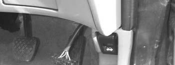
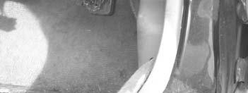
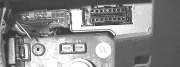


5 DIAGNOSTIC SOCKETS ROVER & MG ROVER MEMS + 5AS MGF MINI
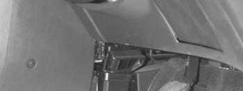


6 DIAGNOSTIC SOCKETS ROVER & MG ROVER ZS 180 ZT FREELANDER (CAB)
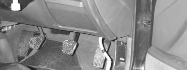
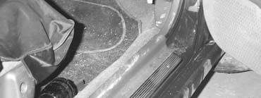


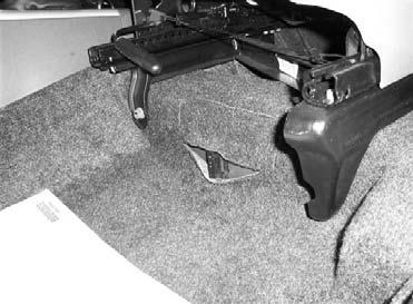
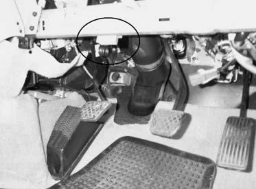
7 DIAGNOSTIC SOCKETS ROVER & MG ROVER 600 (SRS) 100 CITY 600
8 GENERAL OPERATION INTRODUCTION SYSTEM DESCRIPTION (5AS ALARM SYSTEM) There are a number of different systems fitted across the Rover vehicle range, which vary slightly. The systems can only be enabled and disabled using the Key Fob (PLIP). If the car is locked with the mechanical key only, then the alarm is not enabled. There are three ways the alarm works, one is to enable an ultrasonic alarm, the second Perimetric protection and the other engine immobilisation. In addition to this it also operates the central locking. When the system is armed or disarmed the hazard lights will flash depending on which operation is performed. If the doors lock but the hazard lights do not flash, then it is possible that one of the doors, boot or bonnet is partially open. PLIP KEY This is a radio transmitter which has two buttons, one to arm the system and one to disarm. When the system is armed the ALARM LED indicator will flash quickly for 10 seconds, and then flash at a slower frequency. The radio code signal is changed each time the PLIP key is used, and the code is changed both in the handset and also the ECU on the vehicle. If this sequence is broken, then the PLIP key can be re-enabled as follows :- Procedure. 1. Unlock the drivers door using the key. 2. Ensure all doors, bonnet and boot are shut, and if Central Locking is fitted, make sure both front doors are unlocked. 3. Press the PLIP key (Lock button) four times quickly, until the vehicle locks are enabled. ENGINE IMMOBILISATION The engine immobiliser is set as soon as the Perimetric alarm is enabled, which nhibits the engine electrical circuits. Immobilization can only be removed using the PLIP key or the emergency access code (EKA). If the car is not locked using the PLIP key, the immobiliser will be activated 20 seconds after the ignition is switched off, and the drivers door opened. The engine can be re-immobilized by pressing the unlock button on the PLIP key.
9 GENERAL OPERATION PLIP KEY BATTERY REPLACEMENT Ensure the vehicle is unlocked before the following procedure is followed. The battery in the Plip key should last for around 3 years, depending on usage. To change the battery, split the Plip key in half and remove the battery, taking care not to touch the clip or any of the components. Press and hold each of the Plip key buttons for 5 seconds, to discharge any residual voltage in the circuits. Replace the battery, ensuring the side marked with + is facing the clip. Once replaced, snap together both halves of the Plip key. Follow the procedure on the previous page to re-initiate the plip key. PERIMETRIC SYSTEM If the alarm is activated, then the horn will sound for approximately 30 seconds if any of the following are detected :- Boot is opened Bonnet release is opened Ignition is turned to crank position Drivers door button is raised (Only on Central Locking Systems) Drivers door is unlocked (Using Key) Once alarm is activated, it can only be turned off by disarming the alarm. If it is not disarmed the ECU stores a fault. Then if the alarm is disarmed later, the alarm LED will flash rapidly until the ignition is turned on or the alarm is re-armed. TAMPER PROTECTION The system is fitted with tamperproof protection on vehicles with Central Locking. This enables the alarm if the drivers door button or the actuator switch wires are tampered with. VEHICLE BATTERY Ensure the Alarm is disabled before removing the vehicle battery, otherwise the alarm will sound on re-connection.
10 GENERAL OPERATION ENGINE IMMOBILISATION OVERRIDE If the Plip key is lost or does not function, the emergency access code (EKA) can be used to override the system as follows :- 1. Insert the key into the drivers lock, and turn to the lock position. 2. Hold the key in this position for 5 seconds. 3. Now using the code turn the key to the unlock the number of times of the first digit. 4. Now turn the key to the lock position the number of times of the second digit. 5. Repeat for the last two digits. 6. After the code has been entered, turn the key to the unlock position, and check to see whether the Alarm LED has stopped flashing, and the engine will start. If an error is made, open and close the door and repeat the sequence. If 3 unsuccessful attempts are made, the system will lock out for 10 minutes, before another attempt can be made.
11 SPECIAL FUNCTIONS PROGRAMMING REMOTE PLIP KEYS (LUCAS) VEHICLE SELECTION MENU MINI ROVER 100 ROVER 200 ROVER 400 ROVER MG-F At the VEHICLE SELECTION menu select the required vehicle. Then press the ENTER key. PLIP KEY FUNCTIONS EKA FUNCTION Select the function required. The tester will now attempt to communicate with the ECU. PLEASE WAIT TRYING TO COMMUNICATE ECU IDENTIFICATION LUCAS 5AS If communication is successful the system being tested will be displayed as shown. ECU IDENTIFICATION SPECIAL FUNCTIONS Select SPECIAL FUNCTIONS.
12 SPECIAL FUNCTIONS PROGRAM PLIP KEY Select PROGRAM PLIP KEY. PRESS PLIP LOCK AT LEAST 8 TIMES UNTIL HORN SOUNDS. Press either button on the Plip key very quickly up to 8 times until the horn sounds, which indicates it has been successfully programmed. Repeat up to 4 plip keys. READING EKA CODE Select the EKA function. PLIP KEY FUNCTIONS EKA FUNCTIONS TURN IGNITION ON The display should show the EKA code and the sequence required to input the code. NOTE : EKA numbers can go up to 15. READ EKA CODE UNLOCK 6 TURNS LOCK 1 TURNS UNLOCK 11 TURNS LOCK 11 TURNS
13 SPECIAL FUNCTIONS PROGRAMMING EKA CODE READ EKA CODE SPECIAL FUNCTIONS To program a new EKA code select special functions from the menu and press ENTER. WRITE EKA CODE Select WRITE EKA CODE. SECURITY CODE Insert new EKA code. Please make a note of this and advise the customer. SECURITY CODE If correct press ENTER to proceed. IS THIS CORRECT OK=ENTER CLEAR=BACK DISCONNECT tester FROM VEHICLE After the code has been programmed, disconnect the tester and then re-connect to check the code has been written correctly.
14 SPECIAL FUNCTIONS PROGRAMMING REMOTE PLIP KEYS (GM 6 ROVER 75) VEHICLE SELECTION MENU REMOTE FUNCTIONS At the VEHICLE SELECTION menu select the required vehicle. Then select REMOTE FUNCTIONS press the ENTER key. GM-6 Select the GM-6 system. SWITCH IGNITION ON The tester will now attempt to communicate with the ECU. ECU IDENTIFICATION ROVER GM-6 REMOTES The ECU Identification will be displayed. ECU IDENTIFICATION FAULT CODES LIVE DATA SPECIAL FUNCTIONS Select SPECIAL FUNCTIONS.
15 SPECIAL FUNCTIONS PROGRAMMING REMOTE PLIP KEYS (GM 6 ROVER 75) REMOTE STATUS READ REMOTE ID PROGRAM REMOTE The MENU with the following options will then be displayed. REMOTE STATUS REMOTE SLOT 0 USED REMOTE SLOT 1 USED REMOTE SLOT 2 USED REMOTE SLOT 3 UNUSED REMOTE IDENTIFICATION 1? ? ? SECURITY CODE FWEQR IS THIS CORRECT OK=ENTER CLEAR=BACK SWITCH IGNITION OFF REMOTE STATUS The DISPLAY will show which memory slots are used. NOTE : IF YOU ERASE ONE OF THE EX- ISTING REMOTES FROM THE MEMORY AND YOU DO NOT HAVE THE BAR CODE, IT CANNOT BE PROGRAMMED IN AGAIN. READ REMOTE ID This function displays the remote ID numbers, but these numbers are not complete and cannot be used. PROGRAM REMOTE Select the required remote memory slot that you want to program the new remote into. Insert the BAR CODE for the remote being programmed. Then SWITCH IGNITION OFF.
16 SPECIAL FUNCTIONS PROGRAMMING REMOTE PLIP KEYS (GM 6 ROVER 75) * * * * * The tester will display moving stars while programming the remote control. SWITCH IGNITION ON Switch ignition ON. PLEASE WAIT The screen will display PLEASE WAIT. Then return to the main menu and the procedure is complete.

17 SPECIAL FUNCTIONS PROGRAMMING REMOTES (PEKTRON SYSTEM) VEHICLE SELECTION MENU REMOTES EMS IMMOBILISER Then select REMOTES and press the ENTER key. MG ZR MG ZS MG TF MG ZT Example : Remote controls. Select the required vehicle. VEHICLE SELECTION MENU REMOTE FUNCTIONS Select REMOTE FUNCTIONS. SWITCH IGNITION ON Switch ignition ON and press the ENTER button. ACCESS GAINED TRYING TO COMMUNICATE The tester will communicate with the ECU and display ACCESS GAINED of OK.
18 SPECIAL FUNCTIONS PROGRAMMING REMOTES (PEKTRON SYSTEM) ECU IDENTIFICATION SPECIAL FUNCTIONS Select SPECIAL FUNCTIONS. EKA CODE PROGRAM REMOTE Select the EKA code. EKA CODE PLEASE ENSURE ALL DOORS CLOSED AND IMMOBILISER ARMED DOORS ARE LOCKED EKA CODE UNLOCK 9 TURNS LOCK 4 TURNS UNLOCK 8 TURNS LOCK 2 TURNS Ensure all doors are closed. The EKA code will now be displayed. EKA CODE WOULD YOU LIKE TO PROGRAM EKA CODE YES=ENTER NO=BACK
19 SPECIAL FUNCTIONS PROGRAMMING REMOTES (PEKTRON SYSTEM) EKA CODE ONCE EKA CODE IS ENTERED YOU MUST WAIT 5 MINS BEFORE ATTEMPTING TO START CAR OR PROGRAM FOB Procedure complete. EKA CODE PROGRAM REMOTE Select PROGRAM REMOTE. PROGRAM REMOTES PLEASE ENSURE IMMOBILISER IS DISARMED BEFORE PROCEEDING CONTINUE YES=ENTER NO=BACK PROGRAM REMOTES WARNING ALL REMOTES MUST BE PRESENT IF NOT THEY WILL BE ERASED CONTINUE YES=ENTER NO=BACK NOTE : Ensure IMMOBILISER is dissarned using working remote or EKA code. DO NOT proceed if it is not disarmed. NOTE : ALL remotes to be programmed must be present.
20 SPECIAL FUNCTIONS PROGRAMMING REMOTES (PEKTRON SYSTEM) PROGRAM REMOTES ALL CURRENT REMOTES WILL BE REINIT PRESS EACH CURRENT REMOTE IN TURN HORN SHOULD SOUND IF NOT EXIT YES=ENTER NO=BACK PROGRAM REMOTES READY TO PROGRAM NEW REMOTES PLEASE ENTER BARCODE IGNORING 1st & LAST LETTERS/NUMBERS SECURITY CODE Program remotes CURRENT working remotes by pressing one of the buttons on each remote. The HORN should sound for each one. Once CURRENT remotes are programmed press ENTER to continue. To program the NEW remotes a BARCODE is require for each remote. Without the barcode the remotes cannot be programmed. Enter the barcode using the keypad, letters numbers and characters. NOTE : Barcodes can be made up from ANY character, even %. : ; and SPACES etc etc. PROGRAM REMOTES PROGRAM NEXT REMOTE OK=ENTER CLEAR=BACK To program more remotes press OK, if complete press the back button. PROGRAM REMOTES PLEASE TURN IGNITION OFF TEST REMOTE Then turn ignition OFF and test all remotes for functionality.
21 SPECIAL FUNCTIONS RE-CODE ECU s (MEMS 1.6, 1.9 & 2J) VEHICLE SELECTION MENU IMMOBILISER EMS At the VEHICLE SELECTION menu select the required system. Then press the ENTER key. VEHICLE SELECTION MENU MEMS 1.6 MEMS 1.9 MEMS 2J Select the required EMS system VEHICLE SELECTION MENU RE-CODE ECU Select RE-CODE ECU TURN IGNITION ON Turn Ignition ON and press the ENTER key. PLEASE WAIT TRYING TO COMMUNICATE PROCEDURE COMPLETE If re-coding is successful, the tester should indicate procedure complete. Disconnect tester and start vehicle.
22 TIPS & HINTS GENERAL 1. If the Plip key does not operate, it could be one of the following causes:- Bad connection at 5AS ECU plug. Plip Key inoperative or ECU de-programmed. System in lock out due to other radio interference. 2. Alarm LED not working, this could be the failure of LED unit, as this is common on Rover 800 vehicles. Replace LED unit. 3. On Rover 416 Automatic Honda PGMFI engine, if the unlock button is pressed on the Plip key while the ignition is switched ON, vehicle will not start. The Alarm bleeper will sound. To re-immobilise turn ignition off and re-start the vehicle. 4. Radio Frequency Colour coding Frequency Colour (ECU/Handset) Countries MHz Blue/Black UK/Ireland MHz Yellow/Yellow France MHz Blue/Purple Germany MHz Blue/Blue Europe (except France, Germany, Switzerland, Italy & Denmark) MHz White/Blue Switzerland & Denmark MHz Green/Green ROW, Italy & Australia MHz Orange/Green Gulf & Japan 5. Socket mix ups are common Green 3 pin for programming remotes White 3 pin for programming MEMS ECU 6. Before programming a MEMS ECU the immobiliser must be disarmed otherwise the error short to ground will be seen. 7. No communication on a Rover/Land Rover may be the indication of a damaged tester - test with ADC145 dongle. 8. Some Rover 420 vehicles have no pin in the diagnostic socket for battery feed (16) -You will need to run a +ve feed to the DLC. battery power. 9. EKA numbers can go up to Maximum of 4 plip keys can be programmed


23 TIPS & HINTS ECU IDENTIFICATION MEMS 1.6 MEMS 1.9 MEMS 2J NOTE :- HAS 2 MAIN CONNECTORS
24 REMOTE CONTROL PROGRAMMING Rover Metro (3AS) The procedure for manually coding the single button plips on a Rover Metro with 3AS is: Procedure 1. System must be disarmed first, turn the ignition on and then off within 3 seconds. 2. Open the tailgate and leave it open 3. Again, turn the ignition on and then off within 3 seconds. 4. If the procedure has been done correctly, the horn will sound briefly and the alarm LED will come on and stay on. 5. Press the button of the first plip to be coded, the fob LED will come on, go off and come back on again. If the 3AS unit accepts that plip, the alarm LED will go off briefly and come back on. 6. Repeat this last procedure to code another plip, the maximum allowed is two. 7. Exit the learning mode by turning the ignition back on. Rover 200 Remote control problems can occur if the remote loses it's code or if the code gets corrupted (this can be caused in several ways) if this has happened these can often be re-coded quite simply (it does vary slightly with model and year) The usual way is to remove the remote battery, push down both buttons for 20 seconds (to discharge the capacitor, the remote then loses whatever code it contained) then, re-fit the remote battery and whilst near the car rapidly depress the dimpled lock button 5-6 times. This should recode the remote. There are model variations, on some you have to have the ignition switched on and the remote near the centre of the dash to recode. 1. Sit in the car. 2. Close all doors, boot and bonnet. 3. Remove battery from remote. 4. Press both buttons several times to discharge any residual charge. 5. Replace battery. 6. Hold down the open button for at least 5 seconds. 7. Release button then press the other one. 8. You may have to press this button a couple of times. 9. If this fails try it again from step one.
25 Advanced Diagnostics Ltd Diagnostics House Eastboro Fields Hemdale Nuneaton CV11 6GL T: +44(0) F: +44(0) W:
ROVER MANUAL CONTENTS APPLICATIONS GENERAL OPERATION SPECIAL FUNCTIONS TIPS & HINTS REMOTE CONTROL PROGRAMMING
 ROVER MG ROVER ROVER MANUAL CONTENTS APPLICATIONS GENERAL OPERATION SPECIAL FUNCTIONS TIPS & HINTS REMOTE CONTROL PROGRAMMING APPLICATIONS VEHICLE SYSTEM YEAR ECU CABLE PROG MINI 5AS 95 ON ADC100 + ADC120/ADC123
COPYRIGHT 2011 LAND ROVER UNLOCKING TECHNOLOGY
 LAND ROVER UNLOCKING TECHNOLOGY 1 VERSION: 2.9 DEC 2011 COPYRIGHT 2011 LANDROVER CONTENTS PAGE APPLICATIONS ADS106 LANDROVER 3 ADS164 LANDROVER 2008 3 DIAGNOSTIC SOCKETS/OBD PORTS LANDROVER 4 GENERAL OPERATION
UNLOCKING TECHNOLOGY RENAULT
 UNLOCKING TECHNOLOGY RENAULT RENAULT MANUAL CONTENTS APPLICATIONS DIAGNOSTIC SOCKETS GENERAL OPERATION SPECIAL FUNCTIONS TIPS AND HINTS REMOTE CONTROL PROGRAMMING APPLICATIONS RENAULT 1234 DTC CLIO I ALL
PEUGEOT & CITROEN VW/AUDI/SEAT/SKODA GENERAL MOTORS
 n PEUGEOT & CITROEN NISSAN VW/AUDI/SEAT/SKODA FORD GENERAL MOTORS ROVER ETE ETE ETF ETF ETM ETEN Version 1.1 07/01 PEUGEOT & CITROEN TRANSPONDER KEYS VEHICLE KEY TYPE IDENT COLOUR PART NO SAXO STANDARD
UNLOCKING TECHNOLOGY GENERAL MOTORS
 UNLOCKING TECHNOLOGY GENERAL MOTORS GM, OPEL, GMHOLDEN MANUAL CONTENTS APPLICATIONS DIAGNOSTIC SOCKETS GENERAL OPERATION SPECIAL FUNCTIONS TIPS & HINTS APPLICATIONS GENERAL MOTORS A 1234 DTC AGILA ALL
CITROEN MANUAL CONTENTS APPLICATIONS GENERAL OPERATION SPECIAL FUNCTIONS TIPS & HINTS REMOTE CONTROL PROGRAMMING
 3 CITROEN CITROEN MANUAL 3 CONTENTS APPLICATIONS GENERAL OPERATION SPECIAL FUNCTIONS TIPS & HINTS REMOTE CONTROL PROGRAMMING 3 APPLICATIONS VEHICLE YEAR SYSTEM CABLE BERLINGO 1997 > 2002 IMMO 1 IMMO 2
COPYRIGHT 2012 NISSAN - INFINITI UNLOCKING TECHNOLOGY
 NISSAN - INFINITI UNLOCKING TECHNOLOGY 1 VERSION: 3.8 JAN 2011 Copyright 2012 NISSAN/INFINITI CONTENTS PAGE APPLICATIONS ADS112 NISSAN 3-4 ADS159 NISSAN CAN & PROX 5 ADS169 NISSAN 2009 6 ADS112 INFINITI
SCHEMATIC AND ROUTING DIAGRAMS
 2004 ACCESSORIES & EQUIPMENT Keyless Entry - Corvette SCHEMATIC AND ROUTING DIAGRAMS KEYLESS ENTRY SCHEMATICS Fig. 1: Driver Door Schematic Courtesy of GENERAL MOTORS CORP. Fig. 2: Passenger Door Schematic
2001 Chevrolet Corvette ACCESSORIES & EQUIPMENT Remote Keyless Entry Systems - Corvette
 DESCRIPTION 2001 ACCESSORIES & EQUIPMENT Remote Keyless Entry Systems - Corvette Remote Keyless Entry (RKE) system is controlled by Remote Function Actuation (RFA) system. Transmitter allows remote control
CITROEN MANUAL CONTENTS APPLICATIONS GENERAL OPERATION SPECIAL FUNCTIONS TIPS & HINTS REMOTE CONTROL PROGRAMMING
 3 CITROEN CITROEN MANUAL 3 CONTENTS APPLICATIONS GENERAL OPERATION SPECIAL FUNCTIONS TIPS & HINTS REMOTE CONTROL PROGRAMMING 3 APPLICATIONS VEHICLE YEAR SYSTEM CABLE BERLINGO 1997 > 2002 IMMO 1 IMMO 2
2002 Dodge Intrepid ES ACCESSORIES & EQUIPMENT Anti-Theft Systems - Concorde, Intrepid & 300M
 DESCRIPTION SENTRY KEY IMMOBILIZER SYSTEM 2002-03 ACCESSORIES & EQUIPMENT Anti-Theft Systems - Concorde, Intrepid & 300M CAUTION: Large metallic objects, or items such as magnetic pass-keys, may cause
2001 Dodge Durango ACCESSORIES & EQUIPMENT' 'Anti-Theft Systems - Dakota & Durango 2001 ACCESSORIES & EQUIPMENT
 DESCRIPTION VEHICLE THEFT SECURITY SYSTEM 2001 ACCESSORIES & EQUIPMENT Anti-Theft Systems - Dakota & Durango Vehicle Theft Security System (VTSS) provides perimeter protection against unauthorized use
Owner's Manual. Remote Security and Convenience System INS0866 8/98
 Remote Security and Convenience System Owner's Manual IMPORTANT NOTE: The operation of the SURESTART as described in this manual is applicable to most vehicles. However, due to the engine type and configuration
FUNCTIONS PROGRAMMING TABLES 4600 CAN/PLIP
 FUNCTIONS PROGRAMMING TABLES CAN/PLIP 7.1 - Programming the functionalities/remote control* and Driver Card* self learning. IMPORTANT: only for PLIP applications and just after the power supply connection
APPLICATIONS MANUAL CONTENTS PEUGEOT & CITROEN 1.1 NISSAN 1.4 VW/AUDI/SEAT/SKODA 1.6 FORD 1.7 GENERAL MOTORS 1.12 ROVER 1.13 MITSUBISHI 1.
 APPLICATIONS MANUAL TIPS & HINTS CONTENTS PAGE PEUGEOT & CITROEN 1.1 NISSAN 1.4 VW/AUDI/SEAT/SKODA 1.6 FORD 1.7 GENERAL MOTORS 1.12 ROVER 1.13 MITSUBISHI 1.14 DAEWOO 1.14 DAIHATSU 1.15 HONDA 1.15 Version
System Programming Instructions
 System Programming Instructions 1 Transmitter programming: A. Open the driver s door (press and hold in brake pedal on Remote Start only system); NOTE: On vehicles with negative polarity door ajar switch
Model PRO 9233N OWNER S MANUAL
 Model PRO 9233N OWNER S MANUAL KEYLESS ENTRY ALARM UPGRADE MODULE Congratulations on your purchase of this automotive Keyless Entry Upgrade Alarm System. This system is a state - of - the - art auto security
FORD MANUAL CONTENTS APPLICATIONS GENERAL OPERATION SPECIAL FUNCTIONS TIPS & HINTS REMOTE CONTROL PROGRAMMING CODED ACCESS SYSTEMS
 FORD FORD MANUAL CONTENTS APPLICATIONS GENERAL OPERATION SPECIAL FUNCTIONS TIPS & HINTS REMOTE CONTROL PROGRAMMING CODED ACCESS SYSTEMS APPLICATIONS VEHICLE TYPE KEYS YEAR SYSTEM CABLE KA PETROL 3 KEYS
SPi Vehicle Application Guide KEYS Pro SD2.
 SPi Vehicle Application Guide KEYS Pro SD2. KEYS vehicle applications Guide for the SPi This guide provides you with vehicle coverage information and processes for your SPi KEYS Pro subscription. For more
CITROEN FORD NISSAN PEUGEOT RENAULT LAND ROVER MITSUBISHI PORSCHE VW/AUDI/SEAT/SKODA ETE ETG ETJ ETK ETEF ETEN ETEE ETEF ETEG. Version 1.
 CITROEN FORD NISSAN PEUGEOT RENAULT LAND ROVER MITSUBISHI PORSCHE VW/AUDI/SEAT/SKODA ETE ETG ETJ ETK ETEF ETEN ETEE ETEF ETEG Version 1.1 07/01 CITROEN XSARA XANTIA SYNERGIE EVASION CENTRAL DOOR LOCK (1
Power Sliding Door (PSD) Diagnostic Approach. Fixing Intermittent Malfunctions. Power Sliding Door (PSD) Diagnostic Information
 Diagnostic Approach. Fixing Intermittent Malfunctions. Power Sliding Door (PSD) Diagnostic Information") Power Sliding Door (PSD) Diagnostic Information Power Sliding Door (PSD) The power sliding door (PSD) provides built-in diagnostics. This assists the service technicians during troubleshooting. The PSD
Power Sliding Door (PSD) Diagnostic Information Power Sliding Door (PSD) The power sliding door (PSD) provides built-in diagnostics. This assists the service technicians during troubleshooting. The PSD
Service Bulletin Immobilizer System (Type 6) (Supersedes , dated February 20, 2009; see REVISION SUMMARY) February 22, 2013
 (Supersedes , dated February 20, 2009; see REVISION SUMMARY) February 22, 2013") Service Bulletin 06-033 Applies To: 2007-09 MDX ALL 2007-12 RDX ALL February 22, 2013 Immobilizer System (Type 6) (Supersedes 06-033, dated February 20, 2009; see REVISION SUMMARY) REVISION SUMMARY This
Service Bulletin 06-033 Applies To: 2007-09 MDX ALL 2007-12 RDX ALL February 22, 2013 Immobilizer System (Type 6) (Supersedes 06-033, dated February 20, 2009; see REVISION SUMMARY) REVISION SUMMARY This
Quick Reference: Immobilizer III Service Procedures
 Notes: Before starting: Read these instructions completely. When working on an Immobilizer system, try to have all the vehicle keys available. Some repairs require the Adaptation of the keys. If you adapt
KEYLESS ENTRY SYSTEM & TIRE PRESSURE MONITOR ACCESSORIES & EQUIPMENT General Motors Corp. - Remote Keyless Entry System
 KEYLESS ENTRY SYSTEM & TIRE PRESSURE MONITOR 1998 ACCESSORIES & EQUIPMENT General Motors Corp. - Remote Keyless Entry System DESCRIPTION Remote Keyless Entry (RKE) system is controlled by Remote Function
Owner s manual for the AVS C-Series car alarm range Models: AVS C5 AVS C4 AVS C3 Owner s manual version: Generation 1, V12
 www.avscarsecurity.com Owner s manual for the AVS C-Series car alarm range Models: AVS C5 AVS C4 AVS C3 Owner s manual version: Generation 1, V12 Thank you for choosing an AVS C-Series car security system.
Model AS-9234E. Owners Guides
 Model AS-9234E Owners Guides This unit is capable of 3 installation methods. Select the guide for your customer that matches the installation in their particular vehicle. PATENTED: www.voxxintlcorp.com/company/patents
Edilock Ltd. For Auto Locksmit Association and POLICE only!!!
 For Auto Locksmit Association and POLICE only!!! Lexus GS Smart Key, IS Smart Key : Key Programming (15 min/fast) LS460 : Unlock + Reset Immo + Reset Smart module + Key Programmimg (fast) LX570 : Unlock
Transponder key ECU 3
 05 2330 DIAGNOSTICS REGISTRATI The key has 3 codes: the key code (immobilizer code), the wireless code and smart code. All of these types need to be registered. Refer to page 05 2219 for the wireless code
VEHICLE THEFT/SECURITY SYSTEMS
 WJ VEHICLE THEFT/SECURITY SYSTEMS 8Q - 1 VEHICLE THEFT/SECURITY SYSTEMS CONTENTS... 6 VEHICLE THEFT SECURITY SYSTEM... 1 VEHICLE THEFT SECURITY SYSTEM INDEX AND DOOR AJAR SWITCH... 3 DRIVER CYLINDER LOCK
POWER LOCK SYSTEMS 8P - 1 POWER LOCK SYSTEMS TABLE OF CONTENTS
 AN POWER LOCK SYSTEMS 8P - 1 POWER LOCK SYSTEMS TABLE OF CONTENTS page GENERAL INFORMATION INTRODUCTION...1 POWER LOCK SYSTEM...1 REMOTE KEYLESS ENTRY SYSTEM...1 DESCRIPTION AND OPERATION CENTRAL TIMER
Vehicle Security System
 Installation Instructions Vehicle Security System PROFESSIONAL INSTALLATION STRONGLY RECOMMENDED Installation Precautions: Roll down window to avoid locking keys in vehicle during installation Avoid mounting
Check with your installation center for features and functions operational on your system.
 Model PE5B Operators Manual RF Upgrade Kit Unlock Button Press once to unlock and disarm alarm. Press and hold 3 seconds for panic alarm where applicable. OPTION 1 Press and release to activate option
DESCRIPTION & OPERATION
 ANTI-THEFT SYSTEM 1998 ACCESSORIES & EQUIPMENT General Motors Corp. - Anti-Theft System DESCRIPTION & OPERATION WARNING: Deactivate air bag system before performing any service operation. See AIR BAG RESTRAINT
Model CSI-300 Owner s Manual
 Model CSI-300 Owner s Manual 4 Button Remote Security System with Dual Stage Shock Sensor IMPORTANT! In order to provide the highest possible level of security to your vehicle, this system is equipped
" MANUALLY OVERRIDING YOUR SYSTEM
 Model PRO 2000aS Owner s Manual 3 Button Remote Security System with Keyless Entry IMPORTANT! In order to provide the highest possible level of security to your vehicle, this system is equipped with selectable
1999 Mercury Cougar ACCESSORIES & EQUIPMENT' 'Passive Anti-Theft Systems - Cougar 1999 ACCESSORIES & EQUIPMENT
 DESCRIPTION 1999 ACCESSORIES & EQUIPMENT Passive Anti-Theft Systems - Cougar Passive Anti-Theft System (PATS) is available on some vehicles. The system is passive in that it does not require any activity
Technical Bulletin AA 304. Central Locking System. m.y. 97
 Technical Bulletin Subject: Model(s): Central Locking System Cabriolet m.y. 97 Group: Number: Date: 01 96 11 Nov. 29, 1996 The following Repair Manual pages are new and will be integrated with the next
OPERATING INSTRUCTIONS
 EZ-1 ONE BUTTON REMOTE START SYSTEM OPERATING INSTRUCTIONS CONGRATULATIONS on your choice of a Cool Start Remote Engine Starter and Keyless Entry with DP Technology by Crimestopper Security Products Inc.
Vehicle Security System
 Installation Instructions Vehicle Security System PROFESSIONAL INSTALLATION STRONGLY RECOMMENDED Installation Precautions: Roll down window to avoid locking keys in vehicle during installation Avoid mounting
Hyundai EXCEL Remote Immobiliser System Installation Manual Revision 1 10/12/99 Part No
 Hyundai EXCEL Remote Immobiliser System Installation Manual Part No. 00243-22500 The Excel remote immobiliser system is central locking compatible. For vehicle's already fitted with Factory central locking,
Volvo SCR testing module
 Volvo SCR testing module Brief module description We design this module to test the Volvo SCR system (subsequently SCR) and its components. Using this module, you can test different SCR components, such
Central locking. Central locking, components
 57-29 Central locking Central locking, components 1 - Door lock actuator, right front Removing and installing Page 57-30 2 - Door lock actuator, sliding door Removing and installing Page 57-30 3 - door
Model AX-510 Owner s Manual
 Model AX-510 Owner s Manual 4 Button Remote Security System with Dual Stage Shock Sensor IMPORTANT! In order to provide the highest possible level of security to your vehicle, this system is equipped with
Model AS-9234 Owners Guide Upgrade Vehicle Security & Remote Start System
 Table Of Contents: Model AS-9234 Owners Guide Upgrade Vehicle Security & Remote Start System Features Options Page 2 Page 2 Arming the System - Active Page 3 Arming the System - Passive (Automatic) Page
Automotive Data Solutions Inc. AVAILABLE FOR : ADS-BLADE AL. Rev. Date: May 31, 2017 Doc. No.: ##39832##
 Automotive Data Solutions Inc. INSTALL GUIDE BLADE-AL(DL)-GM-EN AVAILABLE FOR : ADS-BLADE AL Rev. Date: May 3, 07 Doc. No.: ##3983## GM U.S. PATENT NO. 8,856,780 PLEASE VISIT WWW.IDATALINK.COM FOR COMPLETE
GM2. Alarms & Remote Start. Automotive Data Solutions Inc.
 Alarms & Remote Start Automotive Data Solutions Inc. INSTALL GUIDE ADS-AL(DL)-GM Available for : ADS-AL CA Rev. Date: March 3, 0 Doc. No.: ##8855## 003 GM The brand names and logos found in this guide
THEFT DETERRENT SYSTEM
 THEFT DETERRENT THEFT DETERRENT SYSTEM 1 System Name Power Window Control System THEFT DETERRENT SYSTEM PRECAUTION NOTICE: For initialization: When disconnecting the cable from the negative (-) battery
SCHEMATIC AND ROUTING DIAGRAMS
 2004 ACCESSORIES & EQUIPMENT Theft Deterrent - Corvette SCHEMATIC AND ROUTING DIAGRAMS THEFT DETERRENT SYSTEM SCHEMATICS Fig. 1: Theft Deterrent Relay, Security Indicator, Lighting and Horn References
ENGINE IMMOBILISER SYSTEM
 ENGINE IMMOBILISER ENGINE IMMOBILISER SYSTEM 1 ENGINE IMMOBILISER SYSTEM PRECAUTION NOTICE: When disconnecting the cable from the negative (-) battery terminal, initialize the following systems after the
Automotive Data Solutions Inc. AVAILABLE FOR : ADS-AL CA. Rev. Date: May 31, 2017 Doc. No.: ##39828##
 Automotive Data Solutions Inc. INSTALL GUIDE ADS-AL(DL)-GM-EN AVAILABLE FOR : ADS-AL CA Rev. Date: May 3, 07 Doc. No.: ##3988## GM U.S. PATENT NO. 8,856,780 PLEASE VISIT WWW.IDATALINK.COM FOR COMPLETE
Model: APS-610a Owner s Manual 4 Button Remote Security System with Dual Stage Shock Sensor
 Model: APS-610a Owner s Manual 4 Button Remote Security System with Dual Stage Shock Sensor IMPORTANT! In order to provide the highest possible level of security to your vehicle, this system is equipped
Service Bulletin Immobilizer System (Type 7) February 22, (Supersedes , dated March 6, 2009; see REVISION SUMMARY)
 February 22, (Supersedes , dated March 6, 2009; see REVISION SUMMARY)") Service Bulletin 09-016 Applies To: See VEHICLES AFFECTED February 22, 2013 Immobilizer System (Type 7) (Supersedes 09-016, dated March 6, 2009; see REVISION SUMMARY) REVISION SUMMARY This service bulletin
Service Bulletin 09-016 Applies To: See VEHICLES AFFECTED February 22, 2013 Immobilizer System (Type 7) (Supersedes 09-016, dated March 6, 2009; see REVISION SUMMARY) REVISION SUMMARY This service bulletin
2 WAY REMOTE STARTER & ALARM SYSTEM INSTALLATION GUIDE FCC ID NOTICE
 REV. ARS. WAY REMOTE STARTER & ALARM SYSTEM INSTALLATION GUIDE FCC ID NOTICE This device complies with Part 5 of the FCC rules. Operation is subject to the following conditions:. This device may not cause
GM2 INSTALL GUIDE BLADE-AL(DL)-GM2. Automotive Data Solutions Inc.
-GM2. Automotive Data Solutions Inc.") Automotive Data Solutions Inc. INSTALL GUIDE BLADE-AL(DL)-GM GM Available for : ADS-BLADE AL Rev. Date: March 3, 0 Doc. No.: ##8863## 003 Version FRançaise disponible en ligne au www.bladeuptade.com please
Automotive Data Solutions Inc. INSTALL GUIDE BLADE-AL(DL)-GM GM Available for : ADS-BLADE AL Rev. Date: March 3, 0 Doc. No.: ##8863## 003 Version FRançaise disponible en ligne au www.bladeuptade.com please
TIP SHEET T0937. Installation Tips For RS00/PS00 + ADS-TBSL-PL + SPDT
 Installation Tips For RS00/PS00 + ADS-TBSL-PL + SPDT TIP SHEET T0937 Thank you for purchasing your remote start from MyPushcart.com - an industry leader in providing remote starts to do-it-yourself installers
GM2 OL-AL(MDB)-GM2. Available for : OL-MDB-ALL. please visit for complete product details
-GM2. Available for : OL-MDB-ALL. please visit for complete product details") Omega R&D Inc. INSTALL GUIDE OL-AL(MDB)-GM Available for : OL-MDB-ALL Rev. Date: March 3, 0 Doc. No.: ##887## 003 GM please visit www.caralarm.com for complete product details The brand names and logos
Omega R&D Inc. INSTALL GUIDE OL-AL(MDB)-GM Available for : OL-MDB-ALL Rev. Date: March 3, 0 Doc. No.: ##887## 003 GM please visit www.caralarm.com for complete product details The brand names and logos
Automotive Data Solutions Inc. AVAILABLE FOR : ADS-DL. Rev. Date: May 31, 2017 Doc. No.: ##39830##
 Automotive Data Solutions Inc. INSTALL GUIDE ADS-DL--EN AVAILABLE FOR : ADS-DL Rev. Date: May 3, 07 Doc. No.: ##39830## U.S. PATENT NO. 8,856,780 PLEASE VISIT WWW.IDATALINK.COM FOR COMPLETE PRODUCT DETAILS
VAG Instrument Cluster Reset Cable ADC219
 VAG Instrument Cluster Reset Cable ADC219 User Guide V1.1 Introduction Thank you for your purchase. ADC219 VAG cable connects to the AD pro tester and the vehicle s OBD port and is specifically used in
2-WAY REMOTE STARTING SYSTEM WITH 1 BUTTONS FOR AUTOMATIC TRANSMISSION RED301-2WAY
 2-WAY REMOTE STARTING SYSTEM WITH 1 BUTTONS FOR AUTOMATIC TRANSMISSION RED301-2WAY User Guide For Key WARNING It is the responsibility of the vehicle operator to ensure that their vehicle is parked in
Covers All 430, 440, 441 and CJ Series Advanced Security Systems.
 INSTALL GUIDE Covers All 430, 440, 441 and CJ Series Advanced Security Systems www.ultrastarters.com Technical Support: 866-698-5872 ext 0 support@ultrastarters.com FCC/ID Notice This device complies with
Model PRO-9675FT4 Owner's Manual
 Model PRO-9675FT4 Owner's Manual 4 Button Remote Start Security System With Plug-In Shock Sensor & Starter Disable FEATURES : w 2 Four Button Programmable RF Transmitters w Four Channel Code Learning Receiver
DIAGNOSTIC TROUBLE CODES: TRANSFER CASE MOTOR
 2008 02 Trailblazer/Envoy, 2008 03 Isuzu Ascender DTC-C0306: Motor A or B Circuit Failure Diagnostic Trouble Code C0306 is set once the Transfer Case Control Module detects an open, short-to-ground, or
install guide OEM-IDS(RS)-BM1-[ADS-BM1]-EN
![install guide OEM-IDS(RS)-BM1-[ADS-BM1]-EN](/thumbs/89/99397338.jpg "install guide OEM-IDS(RS)-BM1-[ADS-BM1]-EN") install guide Document number 13171 Revision Date 231121 firmware OEM-IDS(RS)-BM1-[ADS-BM1] hardware ADS-BM1 accessories ADS-USB (REQUIRED) NOTICE The manufacturer will accept no responsability for any
install guide Document number 13171 Revision Date 231121 firmware OEM-IDS(RS)-BM1-[ADS-BM1] hardware ADS-BM1 accessories ADS-USB (REQUIRED) NOTICE The manufacturer will accept no responsability for any
TRITON ERROR CODES ERROR CODE MODEL SERIES DESCRIPTION RESOLUTION
 0 8100, 9100, 9600, 9610, 9615, 9640, No errors 9650, 9700, 9710, 9705, 9750, RL5000 (SDD),RL5000 (TDM), RT2000, 9800, MAKO, SuperScrip 1 9615 Unsolicited note channel 1 2 9615 Unsolicited note channel
OPERATING INSTRUCTIONS
 LCPRO-3 and LCPRO-4 LOW CURRENT REMOTE START SYSTEM OPERATING INSTRUCTIONS CONGRATULATIONS on your choice of a PRO Start Remote Engine Starter and Keyless Entry by Crimestopper Security Products Inc. This
INSTALL GUIDE OL-HA(RS)-HA6P-[OL-RS-HA6]-EN
![INSTALL GUIDE OL-HA(RS)-HA6P-[OL-RS-HA6]-EN](/thumbs/80/82109789.jpg "INSTALL GUIDE OL-HA(RS)-HA6P-[OL-RS-HA6]-EN") INSTALL GUIDE DOCUMENT NUMBER 5699 REVISION DATE 7 FIRMWARE OL-HA(RS)-HA6P-[OL-RS-HA6] HARDWARE OL-RS-HA6 ACCESSORIES OL-LOADER (REQUIRED) RF-0/0/50-EDP (OPTIONAL) LINKR (OPTIONAL) NOTICE The manufacturer
INSTALL GUIDE DOCUMENT NUMBER 5699 REVISION DATE 7 FIRMWARE OL-HA(RS)-HA6P-[OL-RS-HA6] HARDWARE OL-RS-HA6 ACCESSORIES OL-LOADER (REQUIRED) RF-0/0/50-EDP (OPTIONAL) LINKR (OPTIONAL) NOTICE The manufacturer
INSTALL GUIDE COM-HA(RS)-HA6P-[FT-HA6-DC]-EN
![INSTALL GUIDE COM-HA(RS)-HA6P-[FT-HA6-DC]-EN](/thumbs/91/107082835.jpg "INSTALL GUIDE COM-HA(RS)-HA6P-[FT-HA6-DC]-EN") INSTALL GUIDE DOCUMENT NUMBER 49378 REVISION DATE 20180412 FIRMWARE COM-HA(RS)-HA6P-[FT-HA6-DC] HARDWARE FT-HA6-DC ACCESSORIES ADS-USB (REQUIRED) COMPATIBLE RF-KIT (OPTIONAL) DRONE MOBILE DR-2000 (OPTIONAL)
INSTALL GUIDE DOCUMENT NUMBER 49378 REVISION DATE 20180412 FIRMWARE COM-HA(RS)-HA6P-[FT-HA6-DC] HARDWARE FT-HA6-DC ACCESSORIES ADS-USB (REQUIRED) COMPATIBLE RF-KIT (OPTIONAL) DRONE MOBILE DR-2000 (OPTIONAL)
install guide COM-IDS(RS)-BM1-[ADS-BM1]-EN
![install guide COM-IDS(RS)-BM1-[ADS-BM1]-EN](/thumbs/78/77916996.jpg "install guide COM-IDS(RS)-BM1-[ADS-BM1]-EN") install guide Document number Revision Date 50 firmware COM-IDS(RS)-BM-[ADS-BM] hardware ADS-BM accessories ADS-USB (REQUIRED) COMPATIBLE RF-KIT (OPTIONAL) DRONE MOBILE DR-000 (OPTIONAL) NOTICE The manufacturer
install guide Document number Revision Date 50 firmware COM-IDS(RS)-BM-[ADS-BM] hardware ADS-BM accessories ADS-USB (REQUIRED) COMPATIBLE RF-KIT (OPTIONAL) DRONE MOBILE DR-000 (OPTIONAL) NOTICE The manufacturer
INSTALL GUIDE AKX-IDS(RS)-BM1-[ADS-BM1]-EN
![INSTALL GUIDE AKX-IDS(RS)-BM1-[ADS-BM1]-EN](/thumbs/93/111828337.jpg "INSTALL GUIDE AKX-IDS(RS)-BM1-[ADS-BM1]-EN") INSTALL GUIDE DOCUMENT NUMBER 9 REVISION DATE 7 FIRMWARE AKX-IDS(RS)-BM-[ADS-BM] HARDWARE ADS-BM ACCESSORIES ADS-USB (REQUIRED) COMPATIBLE RF-KIT (OPTIONAL) DIRECTED SMARTSTART & ADS-HRN(RS)-SM (OPTIONAL)
INSTALL GUIDE DOCUMENT NUMBER 9 REVISION DATE 7 FIRMWARE AKX-IDS(RS)-BM-[ADS-BM] HARDWARE ADS-BM ACCESSORIES ADS-USB (REQUIRED) COMPATIBLE RF-KIT (OPTIONAL) DIRECTED SMARTSTART & ADS-HRN(RS)-SM (OPTIONAL)
TIP SHEET. Installation Tips for your RS IB-MUX / PKUMUX (D) + SPDT T1205 v1.2 4/3/14. 1 P a g e
 + SPDT T1205 v1.2 4/3/14. 1 P a g e") Installation Tips for your RS-150 + IB-MUX / PKUMUX (D) + SPDT T1205 v1.2 4/3/14 TIP SHEET Thank you for purchasing your remote start from MyPushcart.com - an industry leader in providing remote starts
Installation Tips for your RS-150 + IB-MUX / PKUMUX (D) + SPDT T1205 v1.2 4/3/14 TIP SHEET Thank you for purchasing your remote start from MyPushcart.com - an industry leader in providing remote starts
Model PRO-9775T Owner's Manual 4 Button Remote Start Security System With Plug-In Shock Sensor & Starter Disable
 Model PRO-9775T Owner's Manual 4 Button Remote Start Security System With Plug-In Shock Sensor & Starter Disable FEATURES:! 2 Four Button Programmable RF Transmitters! Four Channel Code Learning Receiver
Model PRO 9649 Owner s Manual
 Model PRO 9649 Owner s Manual 3 Button Remote Security System with Starter Disable, & Keyless Entry IMPORTANT! In order to provide the highest possible level of security to your vehicle, this system is
install guide OEM-IDS(RS)-BM1-[ADS-BM1]-EN
![install guide OEM-IDS(RS)-BM1-[ADS-BM1]-EN](/thumbs/78/76901805.jpg "install guide OEM-IDS(RS)-BM1-[ADS-BM1]-EN") install guide Document number 9 Revision Date 50 firmware OEM-IDS(RS)-BM-[ADS-BM] hardware ADS-BM accessories ADS-USB (REQUIRED) NOTICE The manufacturer will accept no responsability for any electrical
install guide Document number 9 Revision Date 50 firmware OEM-IDS(RS)-BM-[ADS-BM] hardware ADS-BM accessories ADS-USB (REQUIRED) NOTICE The manufacturer will accept no responsability for any electrical
12V PROGRAMMABLE POWER OUT
 Page 1 ACCESSORIES STARTER IGNITION BATTERY WIRES SIDE VIEW BLUE RED YELLOW 30 A 10 A BLUE / WHITE YELLOW WHITE / BLUE WHITE / DOOR TRIGGER See opt. 16 DOOR TRIGGER (input positive) See opt. 16 PARKING
6R / 5-BUTTON SERIES VEHICLE SECURITY SYSTEM
 6R / 5-BUTTON SERIES VEHICLE SECURITY SYSTEM Button 1 Button 2 Button 5 Button 3 Button 4 Standard Features: Two 5-Button Remote Transmitters Status indicator (LED) Valet / override switch Multi-tone siren
INSTALL GUIDE IDL-IDS(RS)-BM1-[ADS-BM1]-EN
![INSTALL GUIDE IDL-IDS(RS)-BM1-[ADS-BM1]-EN](/thumbs/81/83209382.jpg "INSTALL GUIDE IDL-IDS(RS)-BM1-[ADS-BM1]-EN") INSTALL GUIDE DOCUMENT NUMBER 577 REVISION DATE 7 FIRMWARE IDL-IDS(RS)-BM-[ADS-BM] HARDWARE ADS-BM ACCESSORIES ADS-USB (REQUIRED) COMPATIBLE RF-KIT (OPTIONAL) DIRECTED SMARTSTART & ADS-HRN(RS)-SM (OPTIONAL)
INSTALL GUIDE DOCUMENT NUMBER 577 REVISION DATE 7 FIRMWARE IDL-IDS(RS)-BM-[ADS-BM] HARDWARE ADS-BM ACCESSORIES ADS-USB (REQUIRED) COMPATIBLE RF-KIT (OPTIONAL) DIRECTED SMARTSTART & ADS-HRN(RS)-SM (OPTIONAL)
INSTALLATION GUIDE Table of Contents
 CT-3100 Automatic transmission remote engine starter systems. What s included..2 INSTALLATION GUIDE Table of Contents Door lock toggle mode..... 4 Notice...2 Installation points to remember. 2 Features..2
Owner s Guide CA2LED5
 PROFESSIONAL SERIES Owner s Guide For Model: CA2LED5 AS9234E RF Upgrade Kit IMPORTANT NOTE: The operation of the Security and Convenience System as described in this manual is applicable to most vehicles.
Owner s manual for the AVS S-Series car alarm range Models: AVS S5 AVS S4 AVS S3 Owner s manual version: Generation 2, V4
 www.avscarsecurity.com Owner s manual for the AVS S-Series car alarm range Models: AVS S5 AVS S4 AVS S3 Owner s manual version: Generation 2, V4 Thank you for choosing an AVS S-Series car security system.
INSTALL GUIDE IDL-HA(RS)-HA7-[ADS-HA7]-EN
![INSTALL GUIDE IDL-HA(RS)-HA7-[ADS-HA7]-EN](/thumbs/78/77544933.jpg "INSTALL GUIDE IDL-HA(RS)-HA7-[ADS-HA7]-EN") INSTALL GUIDE DOCUMENT NUMBER 090 REVISION DATE 7070 FIRMWARE IDL-HA(RS)-HA7-[ADS-HA7] HARDWARE ADS-HA7 ACCESSORIES ADS-USB (REQUIRED) COMPATIBLE RF-KIT (REQUIRED) DIRECTED SMARTSTART & ADS-HRN(RS)-SM
INSTALL GUIDE DOCUMENT NUMBER 090 REVISION DATE 7070 FIRMWARE IDL-HA(RS)-HA7-[ADS-HA7] HARDWARE ADS-HA7 ACCESSORIES ADS-USB (REQUIRED) COMPATIBLE RF-KIT (REQUIRED) DIRECTED SMARTSTART & ADS-HRN(RS)-SM
PROGRAMMING INSTRUCTIONS
 MING INSTRUCTIONS MING INSTRUCTIONS Keyline S.p.A. 1 VEHICLE MING INSTRUCTIONS All vehicles are assigned a unique Vehicle Identification Number (VIN) when they are manufactured. To determine the vehicle
Holden VZ 3.6L ECU & Powertrain Interface Module Linking Instructions
 Holden VZ 3.6L 2004-2006 ECU & Powertrain Interface Module Linking Instructions Contents Page In Brief PIM Replacement, ECM Replacement 2 VZ 3.6L System Overview 3 PIM Functions 4 PIM Location 4 ECM Functions
Alarms & Remote Start
 Alarms & Remote Start INSTALL GUIDE DOCUMENT NUMBER 5866 REVISION DATE 0607 FIRMWARE OEM-IDS(RS)-BM-[OL-RS-BM] HARDWARE OL-RS-BM ACCESSORIES OL-LOADER (REQUIRED) NOTICE The manufacturer will accept no
PROFESSIONAL INSTALLATION STRONGLY RECOMMENDED
 Installation Instructions CPL Master Module PROFESSIONAL INSTALLATION STRONGLY RECOMMENDED Installation Precautions: Roll down window to avoid locking keys in vehicle during installation Avoid mounting
INSTALL GUIDE OEM-GM(RS)-GM2-[ADS-GM2]-EN
![INSTALL GUIDE OEM-GM(RS)-GM2-[ADS-GM2]-EN](/thumbs/92/109129040.jpg "INSTALL GUIDE OEM-GM(RS)-GM2-[ADS-GM2]-EN") INSTALL GUIDE DOCUMENT NUMBER 0 REVISION DATE FIRMWARE OEM-GM(RS)-GM-[ADS-GM] HARDWARE ADS-GM ACCESSORIES ADS-USB (REQUIRED) NOTICE The manufacturer will accept no responsability for any electrical damage
INSTALL GUIDE DOCUMENT NUMBER 0 REVISION DATE FIRMWARE OEM-GM(RS)-GM-[ADS-GM] HARDWARE ADS-GM ACCESSORIES ADS-USB (REQUIRED) NOTICE The manufacturer will accept no responsability for any electrical damage
INSTALLATION GUIDE. FCC ID NOTICE
 REV.5 RS. ADVANCED REMOTE STARTER INSTALLATION GUIDE www.security.soundstream.com FCC ID NOTICE This device complies with Part 5 of the FCC rules. Operation is subject to the following conditions:. This
LH POWER LOCK SYSTEMS 8P - 1 POWER LOCK SYSTEMS TABLE OF CONTENTS POWER DOOR LOCKS... 1 REMOTE KEYLESS ENTRY... 4 POWER DOOR LOCKS TABLE OF CONTENTS
 LH POWER LOCK SYSTEMS 8P - 1 POWER LOCK SYSTEMS TABLE OF CONTENTS POWER DOOR LOCKS... 1 REMOTE KEYLESS ENTRY... 4 POWER DOOR LOCKS TABLE OF CONTENTS AND POWER DOOR LOCK SYSTEM...1 CENTRAL LOCKING SYSTEM...2
CA611 Owners Manual CAUTION!
 CA611 Owners Manual CAUTION! Be certain that the vehicle is outdoors before using this or any remote vehicle starting device. A running engine produces dangerous carbon monoxide fumes which can be harmful
OPERATING INSTRUCTIONS
 RS2-G3 ONE BUTTON 2-WAY REMOTE START SYSTEM OPERATING INSTRUCTIONS CONGRATULATIONS on your choice of a Cool Start Remote Engine Starter and Keyless Entry with DP Technology by Crimestopper Security Products
Owner s Guide CA2LCD5
 PROFESSIONAL SERIES Owner s Guide For Model: CA2LCD5 AS9234E RF Upgrade Kit IMPORTANT NOTE: The operation of the Security and Convenience System as described in this manual is applicable to most vehicles.
Maxx 3 Installation Guide
 Maxx 3 Installation Guide 2002 Directed Electronics, Inc. Vista, CA N840003 4-02 Table of Contents Important Information....................................................... 3 System Components........................................................
INSTALL GUIDE OEM-GM(RS)-GM2-[OL-RS-GM2]-EN
![INSTALL GUIDE OEM-GM(RS)-GM2-[OL-RS-GM2]-EN](/thumbs/91/105146075.jpg "INSTALL GUIDE OEM-GM(RS)-GM2-[OL-RS-GM2]-EN") INSTALL GUIDE OEM-GM(RS)-GM-[OL-RS-GM]-EN DOCUMENT NUMBER 0 REVISION DATE 0 FIRMWARE OEM-GM(RS)-GM-[OL-RS-GM] HARDWARE OL-RS-GM ACCESSORIES OL-LOADER (REQUIRED) NOTICE The manufacturer will accept no responsability
INSTALL GUIDE OEM-GM(RS)-GM-[OL-RS-GM]-EN DOCUMENT NUMBER 0 REVISION DATE 0 FIRMWARE OEM-GM(RS)-GM-[OL-RS-GM] HARDWARE OL-RS-GM ACCESSORIES OL-LOADER (REQUIRED) NOTICE The manufacturer will accept no responsability
Owner s manual AVS S5 AVS S4 AVS S3
 www.avscarsecurity.com Owner s manual AVS S5 AVS S4 AVS S3 Edition October 2011 Thank you for choosing an AVS S-Series car security system. This range of car alarms and immobilisers has been designed to
Vehicle Security System
 Installation Instructions Vehicle Security System PROFESSIONAL INSTALLATION STRONGLY RECOMMENDED Installation Precautions: Roll down window to avoid locking keys in vehicle during installation Avoid mounting
INSTALL GUIDE FLC-HA(RS)-HA6P-[FLRSHA6]-EN
![INSTALL GUIDE FLC-HA(RS)-HA6P-[FLRSHA6]-EN](/thumbs/83/88785406.jpg "INSTALL GUIDE FLC-HA(RS)-HA6P-[FLRSHA6]-EN") INSTALL GUIDE DOCUMENT NUMBER 49388 REVISION DATE 20180412 FIRMWARE FLC-HA(RS)-HA6P-[FLRSHA6] HARDWARE FLRSHA6 ACCESSORIES FLPROG (REQUIRED) FLRF1/2/4 (OPTIONAL) CARLINK ASCL2 (OPTIONAL) TERMS OF USE:
INSTALL GUIDE DOCUMENT NUMBER 49388 REVISION DATE 20180412 FIRMWARE FLC-HA(RS)-HA6P-[FLRSHA6] HARDWARE FLRSHA6 ACCESSORIES FLPROG (REQUIRED) FLRF1/2/4 (OPTIONAL) CARLINK ASCL2 (OPTIONAL) TERMS OF USE:
VEHICLE THEFT/SECURITY SYSTEMS
 TJ VEHICLE THEFT/SECURITY SYSTEMS 8Q - 1 VEHICLE THEFT/SECURITY SYSTEMS CONTENTS page GENERAL INFORMATION INTRODUCTION... 1... 1 DESCRIPTION AND OPERATION SMART KEY IMMOBILIZER MODULE... 1 INDICATOR LAMP...
Model APS-20B Owner's Manual
 Model APS-20B Owner's Manual 3 Button Vehicle Alarm System With Auxiliary Output FEATURES: 2 Three Button RF Transmitters Three Channel Code Learning Receiver Remote Panic In All Modes Built-In Parking
ERROR RECOVERY ERR R O C D O ES / REC V O E Y R PR C O EDURES E
 ERROR RECOVERY ERROR CODES / RECOVERY PROCEDURES Error Code TDM 00/50 Mech 0 (MiniMech) Meaning Recovery Procedure X Feed failure 4 X Mistracked note at feed 5 X Mistracked note at double detect X Mistracked
MX40 Series II OPERATING & INSTALLATION INSTRUCTIONS DO NOT LEAVE THIS MANUAL IN YOUR VEHICLE. STANDARDS CERTIFIED AS/NZS amendment
 THE RECOGNISED NAME IN SECURITY MX40 Series II STANDARDS CERTIFIED AS/NZS4601 1999 amendment 1 2003 OPERATING & INSTALLATION INSTRUCTIONS DO NOT LEAVE THIS MANUAL IN YOUR VEHICLE MX40II REMOTE SECURITY
INSTALL GUIDE DIR-IDS(RS)-BM1-[FLRSBM1]-EN
![INSTALL GUIDE DIR-IDS(RS)-BM1-[FLRSBM1]-EN](/thumbs/87/97179515.jpg "INSTALL GUIDE DIR-IDS(RS)-BM1-[FLRSBM1]-EN") INSTALL GUIDE DOCUMENT NUMBER 57 REVISION DATE 7 FIRMWARE DIR-IDS(RS)-BM-[FLRSBM] HARDWARE FLRSBM ACCESSORIES FLPROG (REQUIRED) DIRECTED XL- RF-KIT & ADS-HRN(RS)-XL (OPTIONAL) DIRECTED SMARTSTART & ADS-HRN(RS)-SM
INSTALL GUIDE DOCUMENT NUMBER 57 REVISION DATE 7 FIRMWARE DIR-IDS(RS)-BM-[FLRSBM] HARDWARE FLRSBM ACCESSORIES FLPROG (REQUIRED) DIRECTED XL- RF-KIT & ADS-HRN(RS)-XL (OPTIONAL) DIRECTED SMARTSTART & ADS-HRN(RS)-SM