Electronic STEM Kit. 15 Projects-in-1. Documentation
|
|
|
- Kathleen Williams
- 5 years ago
- Views:
Transcription


1 Electronic STEM Kit 15 Projects-in-1 Documentation
2 Online Resource: INDEX
3

 that are always needed with them, and so we call them units as in PSU (Power Supply connector Unit).")


4 About EdgeFX STEM Kit STEM Kits Basics Anatomy of a Block: Each Block has a defined function. Blocks are in different colors and have Block IDs and polarities on them so that you can easily identify and properly mount them on the base. Note: Some Blocks are integrated with other supporting components (ex. resistors) that are always needed with them, and so we call them units as in PSU (Power Supply connector Unit). This was done to simplify the connections you need to make to use them and also to protect the components from damage. Voltage, Current, Resistance The three main electrical quantities are Voltage, Current and Resistance. Voltage is like an overhead water tank filled with water. Water flowing in the pipe is the current and the pipe is the resistance. Thinner the pipe diameter lesser is the water flow and thicker is the pipe higher is the flow. The whole setup is similar to an electric circuit where top of the tank is positive and the ground is the negative where the current flows, like the water flowing to the ground. A battery or a power supply similarly has +ve and -ve. Page 1
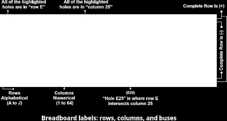
5 Circuit Circuit diagrams, or schematics, are a way to represent a circuit using symbols for each component, with lines representing the connections between the components. Color-coded by function Blocks are grouped into four different categories, which are color-coded. WIRE (BLACK) WIRE: Wire Blocks connect to other systems and let you build circuits in new directions. INPUT (RED, BLUE) Input Blocks accept input from you (Red) or the environment (Blue) and send signals that affect the Blocks that follow. ACCESSORIES Accessories are mechanical components. Note: Occasionally Blocks and accessories get updated, so the features or appearance of your Blocks may differ from those used in this guide. Breadboard (Base) A breadboard is an insulated base plate with several conducting hole points and also electrically separated from each other and are used to try any solderless electronic circuit. The base has rows labeled A-J and columns labeled till 64. Breadboard has some numbers, letters, and plus and minus signs written on them. These labels help you locate certain holes on the breadboard so you can follow directions when building a circuit. Row numbers and column letters help you identify individual holes in the breadboard, just like cells in a spreadsheet. Page 2


6 fundamentals Page 3


7 Blocks Table Block Name Power Indicator Power Supply Connector Unit Resistor 330R Buzzer Block & Component Block ID PI PSU R2 L4 Block Function Power Power Wire Output Block Color Black Black Black Green Polarity Yes Yes No Yes Qty Description 1 A power indicator is a red LED that emits light when combined with a current limiting resistor in series connected to +ve and -ve in a circuit. It is used to indicate the presence of electricity in the circuit. This Block has polarity. Insert the (+) and (-) indicated on the Block in the (+) and (-) rows of the breadboard. 1 A PSU is a micro USB connector, that powers the breadboard by connecting to the USB charger. This Block has polarity. Insert the (+) and (-) indicated on the Block in the (+) and (-) rows of the breadboard. 1 Resistor as the name implies, resists the flow of electricity and are used to control or limit the electricity in a circuit. Increasing circuit resistance reduces the flow of electricity. 1 A buzzer is a sound generating device; it is a polarized device, which means, it has dedicated terminals for positive and negative connections. Buzzer Block has polarity. Insert the (+) and (-) indicated on the Block as per the physical diagram. Page 4
8 Jumper wires J Wire Red Black Blue No As per Requirement The red, black and blue jumper wires come in different lengths to make flexible connections on the breadboard, for times when using CN (connectors) would be difficult. They have rigid pin attached to both ends which are easy to push into the breadboard. They do not change the circuit in any way. Real world example: Extension cord. No CN1-2 CN3-4 CN4-1 A connector unlike jumper is a Block used to provide easy connection between two or more points in a circuit. They do not change the circuit in any way. CN4 Connector CN3 CN Wire Black CN1 Touch Point Breadboard Z1 Base Input - Blue - No - 1 A touch point is a metallic header with two vertical strips. It is used to sense human touch. While both the points are touched same time, it conducts like a wire for micro level electric current to flow in a circuit. 1 A breadboard is an insulated base plate with several conducting hole points and also electrically separated from each other and are used to try any solderless electronic circuit. The base has rows labeled A-J and columns labeled till 64. Breadboard has some numbers, letters, and plus and minus signs written on them. Page 5
9 Switches are essentially binary (meaning double function) devices: they are either completely on ( closed ) or completely off ( open ). S1 Push Button Switch Input Red No 1 A push button is a mechanical switch that allows electricity to flow between its two contacts when held pressed in. When the button is released, the circuit is broken. Real life example: Household electric switch. Diodes are like one-way valves that only let electricity flow in one direction. They are usually small cylinders marked with a band or stripe on one end (this is the direction electricity can flow toward). A light-emitting diode (LED) is a semiconductor device that emits visible light when an electric current passes through it. LEDs have a positive side (called the anode) and a negative side (called the cathode). The cathode side also usually has a flat edge on the plastic part of the LED. It has a very low resistance so it cannot be directly connected to +ve and -ve but is always used in series with an additional external resistance. LED Blocks have polarity. Insert the (+) and (-) indicated on the Block as per the physical diagram. LU3 White LED 10mm Output Green Yes 1 White LED emits bright white light when powered. Transistors are like electronically controlled switches. Bipolar Junction Transistor (BJT) generally have three pins c,b,e. With the printed side facing you the center leg is the base, the right leg is the emitter and the left leg is the collector. Transistor Blocks have polarity. Insert the transistor Block on the breadboard with the flat side and its writing facing against you. BC 547 NPN Transistor QU1 Wire Black BC547 Micro USB Charger Yes 2 When its base terminal is provided with some very little positive electricity, it connects c to e and while electricity to the base point is removed, it disconnects c to e. In this transistor but the direction of electric current flow is only from c to e and can never be from e to c. The charger converts the 230 volts of electricity in the socket to the 5 volts that EFX Electronic Learning Kits run on. Ex.Micro USB Phone charger, Power bank. Note: Not included with the kit. Page 6
10 Online Resource: Assembly Procedure and Troubleshooting Exciting Fact! The most exciting fact about the EdgeFX STEM Kits is that you can correlate the Physical diagram, Circuit diagram and the Actual project. Assembly Procedure 1. Identify and match the physical components and their polarity. 2. Place the Breadboard properly, so the rows A to J marked on the breadboard are from top to bottom and the numbers 1 to 64 are from left to right. 3. Follow the physical diagram for the circuit, connecting one component at a time starting with smaller to bigger height components, and lastly the wire jumper. 4. Jumpers color makes no difference to the functioning of the circuit. Black, Red Jumpers are used to indicate polarity in circuits, whereas Blue color jumpers act as plain connectors and is the right way to build circuits. 5. Disconnect the power while working on the project, Always connect the batteries or power supply to your circuit last. 6. Power on the kit to watch that the red power LED glow. If not remove the power immediately and check for either wrong connections or loose contact. 7. You may remove the adhesive sticker from bottom of the breadboard to fix it on any larger surface for ease of handling and also it does not move while mounting the components. Basic Troubleshooting Getting row numbers wrong: It can be difficult to spot such a tiny error! However, it only takes one misplaced wire or component lead to stop a circuit from working completely. This is why you should always carefully check and double-check your wiring before you test a circuit. If your circuit is not working, carefully double-check all your connections and make sure to count the row numbers. Most of the circuit problems are owing to incorrect connections. So always double-check that the circuit assembled exactly matches the diagram for it. Page 7
11 Not pushing the leads in all the way can result in loose connections that lead to strange circuit behavior, like an LED flickering on and off. Make sure that all connections are fully pressed to the holes. Putting components in backwards: For some electronic components, direction matters. Some components have polarity, meaning they have a positive side and a negative side that must be connected correctly. Other components have multiple pins that all serve different functions. Putting these components into your circuit backwards or facing the wrong way will prevent your circuit from functioning properly. If your circuit is not working and it involves any of these components, check to make sure they are inserted the right way. Motor operation: If the motor spins but is not stable, check if the fan blade is properly fixed onto the motor shaft. Be sure that fan blade is at the top of the shaft facing the ceiling. Short circuits: Short circuits occur when "accidental" connections are made on a breadboard between two components that are not supposed to be connected. Make sure the components leads are not touching each other. Never change connections when powered: By far, the easiest way to damage a circuit is to change a connection while the circuit is powered. Warning: SHOCK HAZARD: Power the Blocks only through the USB mobile charger and in no other way. Always verify your connections before connecting the power to a circuit. Never leave a circuit unattended while the power supply is connected. CHOKING HAZARD: Tiny and pointed parts. Children under 3 years to stay away. MOVING PARTS: Do not try to stop the motor or fan during operation. ADULT SUPERVISION: This product is meant for use by adults and children who have gained sufficient proficiency to read and follow directions and warnings. Never try to modify the kit components, as doing so, may compromise safety features in them, and could put the child at risk of minor injury. Note: If any parts are missing or damaged, us at: info@edgefxkits.com. 105, Liberty Plaza, Himayatnagar, Hyderabad , INDIA. Page 8
 Block and PI LED (Power Indicator) Block B New Project as per the physical diagram Description: In electronics when the current flows from the PSU(+) and reaches")
 and PSU(-), the path is incomplete and so it is referred to as open circuit.")
12 Project Documentation A Introduction B Build new project C Retain E Experiment D Activity F Create and Share Project 1 Aim: To demonstrate the concept of open and closed circuits. A PSU (Power Supply Connector Unit) Block and PI LED (Power Indicator) Block B New Project as per the physical diagram Description: In electronics when the current flows from the PSU(+) and reaches the PSU(-), through other components the path is completed and it is called a closed circuit. On the other hand if there is an interruption in the current flow between PSU(+) and PSU(-), the path is incomplete and so it is referred to as open circuit. In all the projects listed below, when the breadboard is powered by connecting the mobile charger pin to the PSU socket, the Path 1 becomes a closed circuit and the PI LED glows. Check for a loose contact if it does not glow. Page 9


13 Project 2 Aim: To demonstrate the Push Button Switch, Buzzer function and how electricity is used to generate sound. A Push Button Switch S1 Block and Buzzer L4 Block B New Project as per the physical diagram Description: PI LED glows in the closed Path 1. When you press the Push Button Switch S1, electric current flows from the PSU(+), through the Push Button Switch (S1) and then through the Buzzer L4, to PSU(-), completing the Path 2 and forming a closed circuit. As soon as the current flows in the closed circuit, the Buzzer L4 starts emitting a sound. When the Push Button Switch S1 is released, the path is interrupted and therefore, the Buzzer L4 goes off. F1 Make a calling bell for yourself. Take a video of your creation. Mail it on info@edgefxkits.com and share it with friends and family. Page 10
, F30(-)) L4 (E30(+), F30(-)) A LED LU3 C Retain Project 2 and Replace the Buzzer L4 with the LED LU3 Description: PI LED")

14 Projects 3 & 4 Project 3 Aim: To demonstrate the LED function and how electricity is used to light up an LED. Replace Buzzer with LED LU3 (D30(+), F30(-)) L4 (E30(+), F30(-)) A LED LU3 C Retain Project 2 and Replace the Buzzer L4 with the LED LU3 Description: PI LED glows in the closed Path 1. As soon as the current flows in the closed circuit Path 2, the LED LU3 glows. When the Push Button Switch S1 is released, the current stops flowing in the circuit and therefore, the LED LU3 goes off. F2 Brighten your doll-house with this creation. Take a video of your creation. Mail it on info@edgefxkits.com and share it with friends and family. Page 11
, F30(+)) LU3 (D30(+), F30(-)) Description: PI LED glows in the closed Path 1.")
 does not harm it because the small voltage of 5v only used, is not large enough to damage it.")
15 Project 4 Aim: To demonstrate how LED s like one-way valves let electricity flow only in one direction. Replace LED in reverse direction LU3 (D30(-), F30(+)) LU3 (D30(+), F30(-)) Description: PI LED glows in the closed Path 1. Reverse the LED LU3 connection and see that the LED LU3 does not glow. LED LU3 is an electronic component that needs to be connected in one direction only. Placing the LED in backwards (meaning reverse direction) does not harm it because the small voltage of 5v only used, is not large enough to damage it. However had the voltage been above 30 volts it would have surely damaged the LED permanently. D1 Learn more about the Diodes and find out if there are any more. Page 12
 E12 E14 Place conductor to test A Jumper J C Retain Project 3 and Replace the Push Button Switch S1 with a Jumper J Description: PI LED glows in")


16 Projects 5 & 6 Project 5 Aim: To demonstrate conductor and insulator of electricity. Replace Push button switch with Jumper J S1 (E12, E14) E12 E14 Place conductor to test A Jumper J C Retain Project 3 and Replace the Push Button Switch S1 with a Jumper J Description: PI LED glows in the closed Path 1. As soon as the current flows in the closed circuit Path 2, across the Push Button Switch S1 and LED LU3, the LED glows. Now leave out the switch as shown in the circuit. When you place a Jumper J or metal paper clip across the terminals, it completes the circuit and the LED LU3 glows. In simple terms, a conductor allows for electric current to flow through it freely, while an insulator cannot. Metals such as copper are conductors, while most non-metallic solids like a piece of wood are good insulators. That is the reason why plastic is used to insulate copper wires, to eliminate possibilities of any electrical hazards when working with live wires. E1 Check and find out, if a material like paper is a good conductor or a poor conductor. D2 Place your fingers across the terminals and the see that the LED does not light. Your body has too high of a resistance to allow enough current to flow to light the LED. If the voltage, which is electrical pressure, was higher, current could be pushed through your fingers and the LED would light. Page 13
17 Project 6 Aim: To demonstrate the use of fuse to make electrical circuits safer. Description: PI LED glows in the closed Path 1. A fuse is nothing more than a short length of low resistance metallic wire designed to melt and separate in the event of excessive current. Fuses are always connected in series with the component(s) to protect them from overcurrent, so that when the fuse blows (opens) it will open the entire circuit and stop current through the component(s) and prevent them from damage. In this project fuse is nothing but a Jumper J (E12, E14) for demo purpose. When the fuse is intact the Path 2 is completed and the LED LU3 emits light. But due to overcurrent if the fuse melts the circuit is an open path, the LED LU3 is put off. You can see this by removing the jumper from the circuit. D3 Fuses protect our homes and appliances. Ask your daddy dear to show you a real fuse. Page 14
 R2 Block B New Project as per the physical diagram Description: PI LED glows in the closed Path 1.")

18 Projects 7 & 8 Project 7 Aim: To demonstrate the function of a Resistor in series with a Buzzer. A Series Resistor (330R) R2 Block B New Project as per the physical diagram Description: PI LED glows in the closed Path 1. Since the Resistor R2 is connected in series connection with the Buzzer L4 in Path 2, the Resistor restricts the current flow; some voltage across the Resistor drops. This causes a reduction in voltage across the Buzzer L4 and the intensity of the sound emitted by the Buzzer L4 decreases to a large extent. You will have a very low sound. D4 Compare the sound intensity of the Buzzer L4 with that of Project 2 to clearly understand the function of a Resistor. Page 15
, F30(-)) L4 (E30(+), F30(-)) C Retain Project 7 and Replace the Buzzer L4 with LED LU3 Description: PI LED glows in the closed Path")

19 Project 8 Aim: To demonstrate how a series Resistor is used to protect an LED. Replace Buzzer with LED LU3 (D30(+), F30(-)) L4 (E30(+), F30(-)) C Retain Project 7 and Replace the Buzzer L4 with LED LU3 Description: PI LED glows in the closed Path 1. Since the Resistor R2 is connected in series connection with the LED LU3, the Resistor restricts the current flow, and some voltage across the Resistor drops. This causes a reduction in voltage across the LED LU3 and the intensity of the light emitted by the LED LU3 reduces. D5 Compare the brightness of the LED in Project 3 to clearly understand the effect of a Resistor on the output load, in this case LED LU3. Page 16


20 Project 9 Aim: To demonstrate how electric circuits can be build to turn on multiple loads at a time without affecting the performance of the other load. B New Project as per the physical diagram Description: PI LED glows in the closed Path 1. The current in this circuit is bifurcated. PI LED glows in closed Path 1. Current flows through Buzzer L4 in closed Path 2 and the Buzzer L4 generates sound. Current flows through LED LU3 in closed Path 3 and the LED LU3 emits light. Both the parallel loads are independent of each other. If the Buzzer L4 fails or the path is open it does not have the effect on working of LED LU3 and vice-versa. E2 Remove one load and see it has any effect on the intensity of the other load. Page 17

, completing the Path 2 and forming a closed circuit.")

21 Projects 10 & 11 Project 10 Aim: To demonstrate the use of electronically controlled switches like Transistors using Push Button Switch for Input and Buzzer for Output. B Build New Project as per the physical diagram A Transistor BC 547 QU1 Block Description: PI LED glows in the closed Path 1. When you press the Push Button Switch S1, electric current flows from the PSU(+), through the Push Button Switch (S1) and then through the Base B of the Transistor QU1, to Emitter E of the Transistor QU1, to PSU(-), completing the Path 2 and forming a closed circuit. Path 3 is then completed, with the flow of current from PSU(+) through the Buzzer and QU1 to PSU(-). QU1 thus acts as an electronic switch and the buzzer sounds. When the Push Button Switch S1 is released, the current flow in Path 2 is interrupted, also interrupting Path 3, and the Buzzer L4 goes off. F3 Create a panic button for your grandmom. Take a video of your creation. Mail it on info@edgefxkits.com and share it with friends and family. Page 18
, F30(+)) L4 (E30(-), F30(+)) C Retain Project 10 and Replace the Buzzer L4 with the LED LU3 Description: PI LED")

22 Project 11 Aim: To demonstrate how transistor as a switch can control an LED output. Replace Buzzer with LED LU3 (D30(-), F30(+)) L4 (E30(-), F30(+)) C Retain Project 10 and Replace the Buzzer L4 with the LED LU3 Description: PI LED glows in the closed Path 1. As soon as Push Button Switch S1 is pressed, Path 2 and thus Path 3 are closed, and the LED glows. When the Push Button Switch S1 is released, the LED LU3 goes off. F4 Create a Ultra Bright LED Torch Light for your daddy dear. Take a video of your creation. Mail it on info@edgefxkits.com and share it with friends and family. Page 19

, completing the Path 2 and forming a closed circuit. Path 3 is then completed, with the flow of current from PSU(+) through the Buzzer and QU1 to PSU(-).")
23 Projects 12 & 13 Project 12 Aim: Get creative with circuits, demonstration of Push Button Switch in reverse function with Buzzer for Output. B Build New Project as per the physical diagram Description: PI LED glows in the closed Path 1. As long as you do not press the Push Button Switch S1, electric current flows from the PSU(+), through the Push Button Switch (S1) and then through the Base B of the Transistor QU1, to Emitter E of the Transistor QU1, to PSU(-), completing the Path 2 and forming a closed circuit. Path 3 is then completed, with the flow of current from PSU(+) through the Buzzer and QU1 to PSU(-). Transistor QU1 thus acts as an electronic switch and the buzzer sounds. But while the Push Button Switch S1 is pressed, the current flow in Path 2 is bypassed to ground PSU(-), not allowing any current to flow into the Base B of the Transistor thus switching it off, therefore interrupting Path 3, and the Buzzer L4 goes off. E3 Change the Buzzer into the reverse direction and see of it still works. State reasons for your conclusions. Page 20
, F30(+)) LU3 (D30(-), F30(+)) C Retain Project 12 and Replace the Buzzer L4 with the LED LU3 Description: PI LED glows in the closed Path 1.")
, not allowing any current to flow into the Base B of the Transistor switching it off, therefore")
24 Project 13 Aim: To try and see for your self if the switch is reverse function works for an LED output. Replace Buzzer with LED L4 (E30(-), F30(+)) LU3 (D30(-), F30(+)) C Retain Project 12 and Replace the Buzzer L4 with the LED LU3 Description: PI LED glows in the closed Path 1. Replace the Buzzer L4 in Project 12 with an LED LU3. As soon as Push Button Switch S1 is pressed, the current through P2 is bypassed PSU(-), not allowing any current to flow into the Base B of the Transistor switching it off, therefore opening the Path 3, and the LED LU3 goes off. When the Push Button Switch S1 is released, the LED LU3 glows again. E4 Replace the Switch with a Conductor (Ex. Jumper) and see if the circuit still works. Page 21

, completing the Path 2 and forming a closed circuit.")
25 Projects 14 & 15 Project 14 Aim: To demonstrate if human body is a good conductor of electricity using human touch as Input and Buzzer as Output. A Touch Point Block B Build New Project as per the physical diagram Description: PI LED glows in the closed Path 1. When you hold the both Touch Points 1 & 2 with your index finger and thumb, the electric current flows from the PSU(+), through the Touch Point Z1 and then through the Base B of the Transistor QU1-B, to Emitter E of the Transistor QU1-B, again to the to Base B of the Transistor QU1-A, to Emitter E of the Transistor QU1-A to PSU(-), completing the Path 2 and forming a closed circuit. Path 3 is then completed, with the flow of current from Base B of the Transistor QU1-A, to Emitter E of the Transistor QU1-A to PSU(-), and the buzzer sounds. This demonstrates that human body is a good conductor of electricity. D6 Connect both the Touch Points with a paper or plastic and see if the buzzer sounds. Page 22
, F30(+)) LU3 (D30(-), F30(+)) C Retain Project 14 and Replace the Buzzer L4 with the LED LU3 Description: PI LED glows in the closed Path 1.")
 connected together.")
26 Project 15 Aim: To demonstrate the amplification of current via darlington Transistor with LED as Output. Replace Buzzer with LED L4 (E30(-), F30(+)) LU3 (D30(-), F30(+)) C Retain Project 14 and Replace the Buzzer L4 with the LED LU3 Description: PI LED glows in the closed Path 1. The circuit operation remains the same. When you hold the both Touch Points 1 & 2 with your index finger and thumb the LED LU3 emits light and vice versa. The Darlington Transistor named after its inventor, Sidney Darlington is a special arrangement of a pair of standard NPN or PNP bipolar junction Transistors (BJT) connected together. The Emitter E of one Transistor is connected to the base of the other to produce a more sensitive Transistor with a larger current gain, useful in applications where current amplification or switching is required. In this project current is made to pass through the finger by holding the Touch Points. Since human body provides a huge resistance, the current needs to be amplified such that the LED glows through the set of Darlington Transistors. D7 Find out if there is any difference in intensity of the LED output in Project 3 and in Project 15. Page 23
27 EMPOWERING STUDENTS TO INNOVATE Push Button Switch Power Indicator Manual Inputs Connectors Jumper wires Power Supply Unit Jumper Power Resistor Transistor White LED Buzzer Outputs Connectors & Wires Touch Point Environmental Inputs EdgeFX STEM Kit 30-in-1 75-in-1 Arduino Step-by-Step Robotics
Basic Electronics Course Part 1
 Basic Electronics Course Part 1 Simple Projects using basic components Following are instructions to complete several basic electronic projects Identify each component in your kit Image 1. [There are other
Series circuits. The ammeter
 Series circuits D o you remember how the parts of the torch on pages 272 3 were connected together? The circuit contained several components, connected one after the other. Conductors, like the metal strip
HOW TO USE A MULTIMETER, PART 4: MEASURING CURRENT (AMPERAGE)
") HOW TO USE A MULTIMETER, PART 4: MEASURING CURRENT (AMPERAGE) By: Rob Siegel First, we discussed how to use a multimeter for measuring voltage, or simply verifying that voltage is present. Last week, we
HOW TO USE A MULTIMETER, PART 4: MEASURING CURRENT (AMPERAGE) By: Rob Siegel First, we discussed how to use a multimeter for measuring voltage, or simply verifying that voltage is present. Last week, we
reflect energy: the ability to do work
 reflect Have you ever thought about how much we depend on electricity? Electricity is a form of energy that runs computers, appliances, and radios. Electricity lights our homes, schools, and office buildings.
Using your Digital Multimeter
 Using your Digital Multimeter The multimeter is a precision instrument and must be used correctly. The rotary switch should not be turned unnecessarily. To measure Volts, Milliamps or resistance, the black
Experimental Procedure
 1 of 19 9/10/2018, 11:03 AM https://www.sciencebuddies.org/science-fair-projects/project-ideas/robotics_p023/robotics/line-following-robot (http://www.sciencebuddies.org/science-fair-projects/projectideas/robotics_p023/robotics/line-following-robot)
Electronics Made Easy 1 Experimental Kit
 MADE EASY - 1 Electronics Made Easy 1 Experimental Kit BATTERY BATTERY CONNECTORS LED RESISTOR EXPERIMENTAL BREAD BOARD DC MOTOR BUZZER LAMP / GLOBE PUSH BUTTON SWITCH Rev : 02 12 OCT 2014 _MADE_EASY_03.DOC
Maker's Tool Works. Written By: Micro. Wiring methods used by MTW Printers using the Rambo Electronics. Wiring Rambo Electronics & Power Supply
 Maker's Tool Works Wiring Rambo Electronics & Power Supply Wiring methods used by MTW Printers using the Rambo Electronics. Written By: Micro 2017 mtw.dozuki.com Page 1 of 10 TOOLS: Screw Drivers (1) Wire
LAB 7. SERIES AND PARALLEL RESISTORS
 Name: LAB 7. SERIES AND PARALLEL RESISTORS Problem How do you measure resistance, voltage, and current in a resistor? How are these quantities related? What is the difference between a series circuit and
UNIT 3: GENErAL ELECTriCAL SySTEM DiAGNOSiS
 Electrical/Electronic Systems UNIT 3: GENErAL ELECTriCAL SySTEM DiAGNOSiS LESSON 3: TEST electrical circuits I. Types of electrical circuit tests and electrical faults A. Different types of electrical
Chapter 2. Battery Charger and Base Assembly
 Chapter 2 Battery Charger and Base Assembly 11 CHAPTER 2. BATTERY CHARGER AND BASE ASSEMBLY 2.1 Section Overview This Lab teaches students how to assemble a Tekbot, in the following steps: Describe the
4 Electric Circuits. TAKE A LOOK 2. Identify Below each switch, label the circuit as a closed circuit or an open circuit.
 CHAPTER 17 4 Electric Circuits SECTION Introduction to Electricity BEFORE YOU READ After you read this section, you should be able to answer these questions: What are the three main parts of a circuit?
Basic voltmeter use. Resources and methods for learning about these subjects (list a few here, in preparation for your research):
:") Basic voltmeter use This worksheet and all related files are licensed under the Creative Commons Attribution License, version 1.0. To view a copy of this license, visit http://creativecommons.org/licenses/by/1.0/,
Basic voltmeter use This worksheet and all related files are licensed under the Creative Commons Attribution License, version 1.0. To view a copy of this license, visit http://creativecommons.org/licenses/by/1.0/,
12 Electricity and Circuits
 12 Electricity and Circuits We use electricity for many purposes to make our tasks easier. For example, we use electricity to operate pumps that lift water from wells or from ground level to the roof top
Bill of Materials: Spinning top brushless DC motor PART NO
 Spinning top brushless DC motor PART NO. 2171006 The heart of this kit consists of a bifilar wound coil driven with two NPN transistors. While the circuit is easy, the coil will be tedious to wind since
Things to do at home
 presents Things to do at home Things to do at home Now that you have visited the Gadget Factory and learned the basics of circuitry to make your very own flashing badge, we ve got some other great activities
Circuit Basics and Components
 Circuit Basics Electric circuits are arrangements of conductors and components that permit electrical current to flow. A circuit can be as simple as a battery and lamp or as sophisticated as a computer.
Circuit 1: Closed Circuit A closed circuit is a complete circuit that allows current to flow.
 Paper Circuits Gather the following materials: Paper Circuit video tutorials 4 pieces of copper conductive tape (each will be cut into 18 pieces) 5 LEDs (3mm) 1 coin cell battery (3V) 1 binder clip (optional)
4 Electric Circuits. TAKE A LOOK 2. Identify Below each switch, label the circuit as a closed circuit or an open circuit.
 CHAPTER 1 4 Electric Circuits SECTION Introduction to Electricity BEFORE YOU READ After you read this section, you should be able to answer these questions: What are the three main parts of a circuit?
Your web browser (Safari 7) is out of date. For more security, comfort and. the best experience on this site: Update your browser Ignore
 is out of date. For more security, comfort and. the best experience on this site: Update your browser Ignore") Your web browser (Safari 7) is out of date. For more security, comfort and Activitydevelop the best experience on this site: Update your browser Ignore Circuits with Friends What is a circuit, and what
Your web browser (Safari 7) is out of date. For more security, comfort and Activitydevelop the best experience on this site: Update your browser Ignore Circuits with Friends What is a circuit, and what
ELECTRICITY & MAGNETISM - EXAMINATION QUESTIONS (4)
") ELECTRICITY & MAGNETISM - EXAMINATION QUESTIONS (4) 1. Which two electrical quantities are measured in volts? A current and e.m.f. B current and resistance C e.m.f. and potential difference D potential
ELECTRICITY & MAGNETISM - EXAMINATION QUESTIONS (4) 1. Which two electrical quantities are measured in volts? A current and e.m.f. B current and resistance C e.m.f. and potential difference D potential
Overcurrent protection
 Overcurrent protection This worksheet and all related files are licensed under the Creative Commons Attribution License, version 1.0. To view a copy of this license, visit http://creativecommons.org/licenses/by/1.0/,
Electricity and Magnetism
 Electricity and Magnetism Electric Current and Electric Circuits What do you think? Read the statement below and decide whether you agree or disagree with it. Place an A in the Before column if you agree
Laboratory 2 Electronics Engineering 1270
 Laboratory 2 Electronics Engineering 1270 DC Test Equipment Purpose: This lab will introduce many of the fundamental test equipment and procedures used for verifying the operations of electrical circuits.
Science Olympiad Shock Value ~ Basic Circuits and Schematics
 Science Olympiad Shock Value ~ Basic Circuits and Schematics Use a single D battery, a single bare wire and a light bulb. Find four different ways to light the light bulb using only a battery, one wire
THE SOLAR POWERED ANTI-THEFT BAG
 THE SOLAR POWERED ANTI-THEFT BAG Ruchi Mangesh Jadhav 1, Sarika Hari Gaonkar 2, Darshan Kamlesh Khatri 3 Soumya Satish Bangera 4 a ruchimjadhav@gmail.com, b sarikagaonkar01@gmail.com, c darshankk.dk@gmail.com,
Electrical Circuits Discussion Questions:
 Electrical Circuits Discussion Questions: 1) What is electricity? 2) How does an electrical circuit work? 3) What types of materials conduct electrical energy? 4) How is electrical energy measured? 5)
BURGLAR ALARM KIT MODEL K-23. Assembly and Instruction Manual ELENCO
 BURGLAR ALARM KIT MODEL K-23 Assembly and Instruction Manual ELENCO Copyright 2017, 1989 ELENCO Electronics, Inc. Revised 2017 REV-R- 753223 No part of this book shall be reproduced by any means; electronic,
DARK ACTIVATED COLOUR CHANGING NIGHT LIGHT KIT
 ESSENTIAL INFORMATION BUILD INSTRUCTIONS CHECKING YOUR PCB & FAULT-FINDING MECHANICAL DETAILS HOW THE KIT WORKS CREATE SOOTHING LIGHTING EFFECTS WITH THIS DARK ACTIVATED COLOUR CHANGING NIGHT LIGHT KIT
Lab 4.4 Arduino Microcontroller, Resistors, and Simple Circuits
 Lab 4.4 Arduino Microcontroller, Resistors, and Simple Circuits A microcontroller is a "brain" of a mechatronic system that interfaces sensors with a computer. Microcontrollers can perform math operations,
C capacitance, 91 capacitors, codes for, 283 coupling, polarized and nonpolarized,
 Index Numbers and Symbols 555 timer, 164 166 making sound using, setting output speed of, 166 167 using for reaction game speed, 260 261 μf (microfarad), 92 Ω (ohms), 7, 70 A A (amperes), 7 AC (alternating
Electricity. Teacher/Parent Notes.
 Electricity. Teacher/Parent Notes. Caution. The yellow fan. If this is used with 6 Volts, the fan will fly into the air with some force so it is advisable to keep faces well away from it! Batteries. Please
QUASAR KIT No THYRISTOR - TRIAC TESTER
 QUASAR KIT No. 1087 THYRISTOR - TRIAC TESTER GENERAL DESCRIPTION With this new kit Quasar Kit offers you a very useful instrument for your bench that will help you to test THYRISTORS and TRIACS. These
Chapter 21 Practical Electricity
 Chapter 21 Practical Electricity (A) Electrical Power 1. State four applications of the heating effect of electricity. Home: o Used in electric kettles o Used in electric irons o Used in water heaters
HOW IS ELECTRICITY PRODUCED?
 ELECTRICITY HOW IS ELECTRICITY PRODUCED? All electricity is produced from other sources of energy. Hydroelectricity is produced from the stored energy of water held back by a dam. As the water runs downhill
CHAPTER 6.3: CURRENT ELECTRICITY
 CHAPTER 6.3: CURRENT ELECTRICITY These components are used in electric circuits. TASK: Draw how you could make this lamp light. Electricity will only flow through a complete circuit. The battery, wires
Two type of materials
 Two type of materials Conductor: A conductor allows electric current to pass through. Example: Copper, iron, nickel, graphite, etc. Conductors are also known as metals. Wires and strips of metals conduct
Stay Safe Around Electricity Teacher s Guide
 Stay Safe Around Electricity Teacher s Guide INTRODUCTION The Stay Safe Around Electricity activity booklet can be used as a follow-up to an electric utility presentation or as a stand-alone piece to teach
SNC1D PHYSICS 4/6/2013. THE CHARACTERISTICS OF ELECTRICITY L Electrical Resistance (P ) Electrical Resistance. Electrical Resistance
 Electrical Resistance. Electrical Resistance") SNC1D PHYSICS THE CHARACTERISTICS OF ELECTRICITY L Electrical Resistance (P.441-443) Electrical Resistance Have you ever noticed that when you recharge your cellphone, MP3 player, or laptop computer, the
SNC1D PHYSICS THE CHARACTERISTICS OF ELECTRICITY L Electrical Resistance (P.441-443) Electrical Resistance Have you ever noticed that when you recharge your cellphone, MP3 player, or laptop computer, the
METROLOGIC INSTRUMENTS, INC. MX001 Industrial Control Interface Installation and User s Guide
 METROLOGIC INSTRUMENTS, INC. MX001 Industrial Control Interface Installation and User s Guide Copyright 2007 by Metrologic Instruments, Inc. All rights reserved. No part of this work may be reproduced,
Yaskawa Electric America Unit Troubleshooting Manual Section One: Introduction & Checks Without Power GPD 506/P5 and GPD 515/G5 (0.
 Yaskawa Electric America Unit Troubleshooting Manual Section One: Introduction & Checks Without Power GPD 506/P5 and GPD 515/G5 (0.4 ~ 160kW) Page 1 Introduction This manual is divided into three sections:
Unit 3 Lesson 3 Electric Circuits. Copyright Houghton Mifflin Harcourt Publishing Company
 A Complete Circuit What are the parts of an electric circuit? An electric circuit is a complete, closed path through which electric charges can flow. All electric circuits contain three basic parts: an
Quiz Buzzer. Build Instructions. Issue 1.2
 Build Instructions Issue 1.2 Build Instructions Before you put any components in the board or pick up the soldering iron, just take a look at the Printed Circuit Board (PCB). The components go in the side
Contacts The moveable contact, which is the one affected by the armature is sometimes referred to as the hinge contact.
 Relays & Wiring 101 Basically, a relay is an electrically operated, remotely controlled switch. A simple electromagnetic relay is an adaptation of an electromagnet. It consists of a coil of wire surrounding
7.9.2 Potential Difference
 7.9.2 Potential Difference 62 minutes 69 marks Page 1 of 20 Q1. A set of Christmas tree lights is made from twenty identical lamps connected in series. (a) Each lamp is designed to take a current of 0.25
Cabrillo College Physics 10L. LAB 7 Circuits. Read Hewitt Chapter 23
 Cabrillo College Physics 10L Name LAB 7 Circuits Read Hewitt Chapter 23 What to learn and explore Every electrical circuit must have at least one source (which supplies electrical energy to the circuit)
INVESTIGATION ONE: WHAT DOES A VOLTMETER DO? How Are Values of Circuit Variables Measured?
 How Are Values of Circuit Variables Measured? INTRODUCTION People who use electric circuits for practical purposes often need to measure quantitative values of electric pressure difference and flow rate
V=I R P=V I P=I 2 R. E=P t V 2 R
 Circuit Concepts Learners should be able to: (a) draw, communicate and analyse circuits using standard circuit symbols using standard convention (b) apply current and voltage rules in series and parallel
Using Electricity. Summary Notes. 1. From the Wall Socket Household appliances. Earth wire and safety.
 Using Electricity Summary Notes Section Content 1. From the Wall Socket Household appliances. Earth wire and safety. 2. Alternating and Direct Battery and transformer. Current Circuit diagrams. Current
REAR BIKE LIGHT KIT TEACHING RESOURCES. Version 2.0 MASTER THE ART OF SOLDERING WITH THIS
 TEACHING RESOURCES SCHEMES OF WORK DEVELOPING A SPECIFICATION COMPONENT FACTSHEETS HOW TO SOLDER GUIDE MASTER THE ART OF SOLDERING WITH THIS REAR BIKE LIGHT KIT Version 2.0 Index of Sheets TEACHING RESOURCES
Class X Chapter 09 Electrical Power and Household circuits Physics
 EXERCISE- 9 (A) Question 1: Write an expression for the electrical energy spent in flow of current through an electrical appliance in terms of current, resistance and time. Solution 1: Electrical energy,
Design and Technology: Electronic Products
 Write your name here Surname Other names Pearson Edexcel GSE entre Number Design and Technology: Electronic Products Paper 2: Knowledge and Understanding of Electronic Products Tuesday 19 May 2015 Morning
KI0007EP BICYCLE TAIL LIGHT LED FLASHER PROJECT
 KI0007EP BICYCLE TAIL LIGHT FLASHER PROJECT Designed and Supplied by ABN 26 052 173 154 Unit 4 Cnr Ring Rd & Sturt St, Ballarat Victoria, 3350 P.O Box 4043, Alfredton, 3350 www.wiltronics.com.au sales@wiltronics.com.au
Micro USB Lamp Kit ESSENTIAL INFORMATION. Version 2.1 DESIGN A STYLISH LAMP WITH THIS
 ESSENTIAL INFORMATION BUILD INSTRUCTIONS CHECKING YOUR PCB & FAULT-FINDING MECHANICAL DETAILS HOW THE KIT WORKS DESIGN A STYLISH LAMP WITH THIS Micro USB Lamp Kit Version 2.1 Build Instructions Before
Art. No. EC-315. Art. No. EC-330. Art. No. EC-340 SWITCH-MODE BATTTERY CHARGER CONTENTS IMPORTANT SAFETY PRECAUTIONS... 2
 SWITCH-MODE BATTTERY CHARGER CONTENTS IMPORTANT SAFETY PRECAUTIONS... 2 DESCRIPTION AND FEATURES... 3 CHARGING STAGES... 4 Art. No. EC-315 Art. No. EC-330 Art. No. EC-340 PROTECTIONS... 5 INSTALLATION...
Lesson Plan: Electricity and Magnetism (~100 minutes)
") Lesson Plan: Electricity and Magnetism (~100 minutes) Concepts 1. Electricity and magnetism are fundamentally related. 2. Just as electric charge produced an electric field, electric current produces a
Lesson Plan: Electricity and Magnetism (~100 minutes) Concepts 1. Electricity and magnetism are fundamentally related. 2. Just as electric charge produced an electric field, electric current produces a
7.9.1 Circuits. 123 minutes. 170 marks. Page 1 of 56
 7.9.1 Circuits 123 minutes 170 marks Page 1 of 56 ## The diagram shows a motor, connected to a 240 V supply, driving a water pump. The ammeter reads 5.0 A. (a) How much charge flows through the motor in
Prusa i3 Printer Assembly Guide
 Prusa i3 Printer Assembly Guide Special thanks to Carlos Sanchez and Miguel Sanchez for the graphics. All graphics captured from their great animation: http://www.carlos-sanchez.com/ Prusa3/ For copyright
1. Spare Change Flashlight
 . Spare Change Flashlight.. Battery introduction (Adapted from reference 0) Today, batteries are all around us. They power computers, phones, smoke detectors, etc. Batteries are critical not only for current
FiveFish Studios PSU-2448Plus+ Assembly Guide
 FiveFish Studios PSU-2448Plus+ Assembly Guide Copyright 2015-2017 FiveFish Audio Revision 1.02-20171105 No part of this document may be reproduced, either mechanically or electronically, posted online
Electricity All Around Us
 ELECTRICITY ALL AROUND US, COMPLETE MODULE MATERIALS MODULE TEST ANSWER KEY Section 1: or False 1. Damaged wires can cause fires in your home. 2. Appliances placed close to water are a safety hazard. 3.
Phase 1 Workshop Home Study Guide
 Phase 1 Workshop Home Study Guide Vehicle Electrical-Electronics Troubleshooting Training Written and Developed by Vince Fischelli Director of Training Veejer Enterprises Inc. / Garland, Texas U.S.A. Phone:
Can You Light the Bulb?
 3-5 Physical Science Southern Nevada Regional Professional Development Program Can You Light the Bulb? INTRODUCTION Electrical energy is easily transferred through loops that we call circuits. This activity
User Manual EN FIRE STICK
 User Manual EN FIRE STICK 1 V V I Thank you for purchasing one of our products! We are truly honored to be able to serve you and provide you with the best Experience possible. If you ve enjoyed our product,
QUASAR ELECTRONICS KIT No ELECTRONIC CAR IGNITION
 QUASAR ELECTRONICS KIT No. 1058 ELECTRONIC CAR IGNITION General Description The advantages of having an electronic ignition in your car are well known. Let us mention them again: 1. Perfect burning of
11.1 CURRENT ELECTRICITY. Electrochemical Cells (the energy source) pg Wet Cell. Dry Cell. Positive. Terminal. Negative.
 pg Wet Cell. Dry Cell. Positive. Terminal. Negative.") Date: SNC1D: Electricity 11.1 CURRENT ELECTRICITY Define: CIRCUIT: path that electrons follow. CURRENT ELECTRICITY: continuous flow of electrons in a circuit LOAD: device that converts electrical energy
Date: SNC1D: Electricity 11.1 CURRENT ELECTRICITY Define: CIRCUIT: path that electrons follow. CURRENT ELECTRICITY: continuous flow of electrons in a circuit LOAD: device that converts electrical energy
E D C K R A E T S I D TURNOUT CONTROLLER 8S USER MANUAL
 S I D E T R A C K E D TURNOUT CONTROLLER 8S USER MANUAL INDEX 1. WHAT YOU SHOULD HAVE 3 2. FEATURES OF THE 3 3. WARRANTY 3 4. ABOUT THIS MANUAL 3 5. CONNECTORS AND DESCRIPTIONS 3 6. WIRING 7 6.1. CONTROL
Lab Electronics Reference: Tips, Techniques, and Generally Useful Information for the Labs
 ENGR 112 September 16, 14 Lab Electronics Reference: Tips, Techniques, and Generally Useful Information for the Labs This guide contains some useful reference information to help get you started on your
Student book answers Chapter 1
 Physics P2 Unit Opener Picture Puzzler: Key Words Picture Puzzler: Close up Everest, newtonmeter, Earth, remote, gear, yellow The key word is energy. copper wires P2 1.1 Charging up In-text A positive,
Diagnostic. Enlightenment. The Path to
 The Path to Diagnostic Enlightenment BY JORGE MENCHU If you don t know where you re going, any road will take you there. When it comes to automotive troubleshooting, the right road is the shortest path
Understanding Electricity and Electrical Safety Teacher s Guide
 Understanding Electricity and Electrical Safety Teacher s Guide Note to Instructor: The activities and experiments in this booklet build on each other to develop a student s understanding of electricity
INSTRUCTIONS ASSEMBLY. CONNECT the RESISTOR. The resistor (re-zis-ter) is the tube-shaped piece with two purple legs. Here we go!
 is the tube-shaped piece with two purple legs. Here we go!") BEFORE YOU BEGIN ASSEMBLING YOUR VOICE CHANGER You will need One 9-volt battery Masking tape or clear tape Adult help (if you re under 10) Now remove the parts from the plastic tray. 1 CONNECT the RESISTOR
BEFORE YOU BEGIN ASSEMBLING YOUR VOICE CHANGER You will need One 9-volt battery Masking tape or clear tape Adult help (if you re under 10) Now remove the parts from the plastic tray. 1 CONNECT the RESISTOR
In this installment we will look at a number of things that you can do with LEDs on your layout. These will include:
 Introduction The first article in this series, LEDs 101 - The Basics, served to review the characteristics and use of LED lighting in a garden railway environment. It also generated a host of questions
General Purpose Flasher Circuit
 General Purpose Flasher Circuit By David King Background Flashing lights can be found in many locations in our neighbourhoods, from the flashing red light over a stop sign, a yellow warning light located
OPERATING INSTRUCTIONS
 8 FUNCTION DIGITAL MULTIMETER 90939 OPERATING INSTRUCTIONS 3491 Mission Oaks Blvd., Camarillo, CA 93011 Visit our Web site at http://www.harborfreight.com Copyright 2004 by Harbor Freight Tools. All rights
LETTER TO PARENTS SCIENCE NEWS. Dear Parents,
 LETTER TO PARENTS Cut here and paste onto school letterhead before making copies. Dear Parents, SCIENCE NEWS Our class is beginning a new science unit using the FOSS Magnetism and Electricity Module. We
Write the differences between Electric Line Tester and Screw Driver. When the light of Electric Line Tester glows?
 Line Tester Workbook The line tester is very important tool for a person who works on electricity. In India the supply Voltage is 220 Volt. The electric line testers are designed to work on the specific
Model: PI-140 Power Inverter Converts 12V DC battery power to 120V AC household power
 OWNER S MANUAL Model: PI-140 Power Inverter Converts 12V DC battery power to 120V AC household power READ THE ENTIRE MANUAL BEFORE USING THIS PRODUCT. FAILURE TO DO SO COULD RESULT IN SERIOUS INJURY OR
Batteries n Bulbs: Voltage, Current and Resistance (8/6/15) (approx. 2h)
 (approx. 2h)") Batteries n Bulbs: Voltage, Current and Resistance (8/6/15) (approx. 2h) Introduction A simple electric circuit can be made from a voltage source (batteries), wires through which current flows and a resistance,
Batteries n Bulbs: Voltage, Current and Resistance (8/6/15) (approx. 2h) Introduction A simple electric circuit can be made from a voltage source (batteries), wires through which current flows and a resistance,
TECHNICAL NOTE #4 Revised May 24, BOGART ENGINEERING Two Bar Road, Boulder Creek, CA (831)
") TECHNICAL NOTE #4 Revised May 24, 2004 BOGART ENGINEERING 19020 Two Bar Road, Boulder Creek, CA 95006 (831) 338-0616 TROUBLESHOOTING the TriMetric battery monitor Revised for the TM-2020 TriMetric What
TECHNICAL NOTE #4 Revised May 24, 2004 BOGART ENGINEERING 19020 Two Bar Road, Boulder Creek, CA 95006 (831) 338-0616 TROUBLESHOOTING the TriMetric battery monitor Revised for the TM-2020 TriMetric What
8.2 Electric Circuits and Electrical Power
 8.2 Electric Circuits and Electrical Power Every electrical device uses current to carry energy and voltage to push the current. How are electrical devices designed? What types of parts are used in an
CHAPTER 2. Current and Voltage
 CHAPTER 2 Current and Voltage The primary objective of this laboratory exercise is to familiarize the reader with two common laboratory instruments that will be used throughout the rest of this text. In
SMART LAB PUTTING TOGETHER THE
 PUTTING TOGETHER THE SMART LAB INSTALLING THE SPRINGS The cardboard workbench with all the holes punched in it will form the base to the many cool circuits that you will build. The first step in transforming
RIGrunner. for models 4004USB 4005 / 4005H 4008 / 4008H
 RIGrunner for models 4004USB 4005 / 4005H 4008 / 4008H 4012 www.westmountainradio.com 1020 Spring City Drive Waukesha, WI 53186 262-522-6503 sales@westmountainradio.com 2015 West Mountain Radio, All rights
QUASAR ELECTRONICS KIT No WINDSCREEN WIPER CONTROLLER
 QUASAR ELECTRONICS KIT No. 1093 WINDSCREEN WIPER CONTROLLER General Description This is a very useful accessory for any car. It can adjust the frequency of operation of the windscreen wipers between once
IMPORTANT! DO NOT THROW AWAY THE SHIPPING CARTON AND PACKING MATERIAL
 Operator s Manual IMPORTANT! DO NOT THROW AWAY THE SHIPPING CARTON AND PACKING MATERIAL ii Table of Contents Operator Safety... 1 Introduction... 2 Unpacking and Setup... 3 Unpacking... 3 Setup... 4 ROCKET
PHYSICS MCQ (TERM-1) BOARD PAPERS
 BOARD PAPERS") GRADE: 10 PHYSICS MCQ (TERM-1) BOARD PAPERS 1 The number of division in ammeter of range 2A is 10 and voltmeter of range 5 V is 20. When the switch of the circuit given below is closed, ammeter reading
GRADE: 10 PHYSICS MCQ (TERM-1) BOARD PAPERS 1 The number of division in ammeter of range 2A is 10 and voltmeter of range 5 V is 20. When the switch of the circuit given below is closed, ammeter reading
INSTRUCTION MANUAL. BatteryMINDer. Model SCC515 Maintenance Charger- Solar Controller for use with 5 Watt and 15 Watt Solar Panels
 INSTRUCTION MANUAL Model Maintenance Charger- Solar Controller for use with 5 Watt and 15 Watt Solar Panels OVERVIEW... 2 MOUNTING INSTRUCTIONS... 3 BATTERY CONDITION INDICATOR (BCI)... 5 TESTING BATTERY...
Essential Electricity Homework Exercise 1
 Homework Exercise 1 1. For each of the following electrical symbols, copy the symbol into you jotter and label it using the words below. Word bank resistor, voltmeter, battery, ammeter, bulb V A 2. State
Experimental Procedure
 1 of 14 9/11/2018, 3:22 PM https://www.sciencebuddies.org/science-fair-projects/project-ideas/robotics_p026/robotics/build-a-solar-powered-bristlebot (http://www.sciencebuddies.org/science-fairprojects/project-ideas/robotics_p026/robotics/build-a-solar-powered-bristlebot)
FUN! Protected Under 18 U.S.C. 707
 FUN! Protected Under 18 U.S.C. 707 DC I Lesson Objectives: 1. What is Electricity? 2. Discover the Electron 3. Learn about Conductors and Insulators 4. Learn about Voltage and Current 5. Learn the difference
PURE PHYSICS ELECTRICITY & MAGNETISM (PART I)
") PURE PHYSICS ELECTRICITY & MAGNETISM (PART I) 1 A student walks across a thick carpet and becomes positively charged as his shoes rub on the carpet. When he touches the metal handle of a door, negative
PURE PHYSICS ELECTRICITY & MAGNETISM (PART I) 1 A student walks across a thick carpet and becomes positively charged as his shoes rub on the carpet. When he touches the metal handle of a door, negative
Car Battery Charger Instructions for Use
 BATTERY CHARGER 12Volt 4Amp FOR INDOOR USE ONLY Power Details: Input: 230-240Vac; 50Hz; 52W Output: 12V DC; 2.8A Maximum Charge Rate: 4A RMS Read these instructions before operating this car battery charger
LICENCE TO LIGHTING,TEACHER S BOOK
 Licence to Lighting Teacher s book Licence to Lighting is a small instructional programme intended for the subject natural and technical science in its first level. By working with elementary teaching
Electricity. Chapter 20
 Electricity Chapter 20 Types of electric charge Protons + charge Electrons - charge SI unit of electric charge is the coulomb (C) Interactions between charges Like charges repel Opposite charges attract
INSTALLER S INSTRUCTIONS FOR TRI-METRIC Battery system monitor, Model TM-2025-RV. Contents
 INSTALLER S INSTRUCTIONS FOR TRI-METRIC Battery system monitor, Model TM-2025-RV revised March 14, 2009 IMPORTANT: The wiring installation for this meter, especially the shunt installation must be performed
Arlo Power Distribution Board Kit Rev B (#28996)
") Web Site: www.parallax.com Forums: forums.parallax.com Sales: sales@parallax.com Technical: support@parallax.com Office: (916) 624-8333 Fax: (916) 624-8003 Sales: (888) 512-1024 Tech Support: (888) 997-8267
Web Site: www.parallax.com Forums: forums.parallax.com Sales: sales@parallax.com Technical: support@parallax.com Office: (916) 624-8333 Fax: (916) 624-8003 Sales: (888) 512-1024 Tech Support: (888) 997-8267
The graphs show the voltage across two different types of cell as they transfer the last bit of their stored energy through the torch bulb.
 Q1. A small torch uses a single cell to make the bulb light up. (a) The graphs show the voltage across two different types of cell as they transfer the last bit of their stored energy through the torch
SolarPowerChargeController. Solar Power Charge Controller. By Tarang Thakur Maharaja Agrasen Institute of Technology
 Global Journal of Researches in Engineering: Electrical and Electronics Engineering Volume 16 Issue 8 Version 1.0 Type: Double Blind Peer Reviewed International Research Journal Publisher: Global Journals
Electricity All Around Us
 ELECTRICITY ALL AROUND US, COMPLETE MODULE MATERIALS MODULE TEST Name: Section 1: or. Circle true or false for the following questions. 1. Damaged wires can cause fires in your home. 2. Appliances placed