Operating, Installation and Maintenance Instructions
|
|
|
- Clementine Page
- 5 years ago
- Views:
Transcription


1 Version 03/2015 Technical modifications reserved Page 1 of 14
2 TABLE OF CONTENTS 1. Applicable documents 3 2. Information on intended use 3 3. Design / function Ball valve Sealant / lubrication system 5 4. Storage instructions 6 5. Unpacking and inspection 6 6. Indications on safe installation Preparations Handling Installation Water pressure test Line drying Leak test Maintenance Repair Preparations Repairing the external coating Ball valve with individual parts 12 Version 03/2015 Technical modifications reserved Page 2 of 14
3 1. Applicable documents The actuator manufacturer s operating instructions also need to be followed for ball valves with actuators. Additionally, the order related documenation (especially the drawing) is part of the operating manual. 2. Information on intended use The valve is an extremely sturdy, fully welded ball valve for use in piping systems as a fluid shut-off valve. It consists of a body with pipe connections, a spherical stopper, seals and an operating spindle. The HKSF-W100 ball valve serves exclusively as a shut-off device. The ball valve must not be used to reduce the flow of fluid. The valve should only be moved to the limit of travel (end stop) in the FULLY OPEN or FULLY CLOSED position. The identification label and the associated data sheets indicate the permitted operating data (in particular operating temperature and pressure). Exceeding these values damages the valve and may cause it to rupture. The valve is a closed system. The way the seals are designed ensures permanent technical tightness under the specified operating conditions. The fluid in the valve body can be released via drain or vent ports. These ports represent a hazard due to the blow-off pressure and the release of flammable substances that can form explosive atmospheres in contact with air. Depending on its equipment category, the valve may be used in explosion protection zones 1, 2 and 3. Version 03/2015 Technical modifications reserved Page 3 of 14
4 The permissible ambient and fluid temperatures are factored into the design based on the operator s data. II 2G TX Letter "X": Since the temperature of the fluid determines the valve s operating temperature, the operator must specify the temperature class or highest surface temperature, complying with the temperature safety margins from EN Operating temperature C 1 ) Temperature class Up to 80 Up to 95 Up to ) A safety margin of 5 C (EN Section ) was used in the table. T6 T5 T4 Version 03/2015 Technical modifications reserved Page 4 of 14
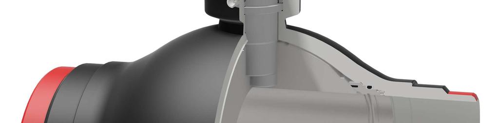
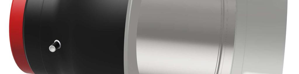
5 3. Design / function 3.1 Ball valve The body of the HKSF-W100 ball valve has been welded to ensure a complete seal. The ball is supported by a journal at the top and bottom (trunnion mounted). The HKSF-W100 ball valve is supplied with one of the following sealing systems: 1. Primary metallic, secondary soft-sealing 2. Metallic sealing only The standard sealing system is primary metallic, secondary soft-sealing. With both systems, floating seating rings are arranged on both sides of the ball valve passage. These can adapt to the ball as necessary. The contact force is increased according to the pressure. Primary metallic, secondary soft-sealing: Soft seals that adapt to the ball as a function of the pressure, independently of the seating rings, are incorporated in the latter. The ball is chromium-plated and the seating rings are made of stainless steel. Metallic sealing only: Each seating ring has a metallic sealing surface but no soft seal. This sealing surface and the ball are coated with tungsten carbide. The valve is supplied with a full bore with a smooth, round passage (piggable) or with a reduced passage. The ball valve can be equipped with flanges, weld ends or other specified connections. 3.2 Sealant / lubrication system According to customers requirements, RMA ball valves can be equipped with integrated sealant systems on the seating rings and / or the spindle sleeve. Access is by means of a nipple (e.g. Alemite-Screw AEX 7/8"), either directly at the ball valve or through vertically extended pipes. The systems are equipped with double non-return valves and, if required, are pre-filled with special non-gumming sealing greases. We recommend the following sealants / greases: For emergency sealing : Equa-Lube Eighty For emergency sealing and greasing : Ceritol.SAS 325 Version 03/2015 Technical modifications reserved Page 5 of 14
6 4. Storage instructions Ball valves should remain in their original packaging during the entire storage period. To prevent damage, the protective caps should be left on the weld / flange ends until installation. Ball valves must always be stored in the FULLY OPEN position. Valves should be stored in a closed, dry building. 5. Unpacking and inspection Ball valves must be unpacked with the necessary care. After unpacking, they should be inspected for transport damage. Ball valves are supplied in the FULLY OPEN position with protective caps at both ends. It is recommended to perform a functional check on valves after a lengthy storage period. 1. Fully close and open the ball valve. 2. Use any available access point to the valve body (drain or vent port) to check for leaks with nitrogen at 6 bar. Version 03/2015 Technical modifications reserved Page 6 of 14

7 6. Indications on safe installation 6.1 Preparations Ensure that no explosive atmosphere exists or develops during assembly and dismantling. Prior to installation, check that the size, the pressure and the materials used meet the specified requirements. Also remove any impurities that have formed during lengthy storage periods prior to installation. 6.2 Handling For lifting purposes, slings should be placed around the ball valve only and not the gear mechanism. Lifting points: Version 03/2015 Technical modifications reserved Page 7 of 14

8 6.3 Installation To avoid damaging the ball and seating rings, ball valves should be welded in place / installed in the FULLY OPEN position in which they were supplied. In case of a fail safe closed actuator the following has to be observed: 1. If the actuator is supplied in mounted condition, the ball valve is in closed position. Before welding, the ball valve has to be put into open position! In this case you will find the indication Attention, ball valve in closed position on the ball valve. 2. If the actuator is supplied separately, the ball valve is supplied in open position. The actuator has to be put into open position before assembly (and after welding) and has to be mounted in this way. Only after this the ball valve may be closed again. During welding, the temperature on the valve body in area A (see sketch) should not exceed 120 C. Weld the valve in place only in the FULLY OPEN position. Use only arc welding. Max. 120 C Max. 120 C After welding and before the ball valve is operated for the first time, the line system must be rinsed thoroughly to remove impurities such as welding debris (cinder, scale, rust, etc.) that could damage the sealing elements. The valve must be fitted using hose / tubing systems that are capable of dissipating electrostatic charges or a direct, electrostatically conductive connection to the earth potential Version 03/2015 Technical modifications reserved Page 8 of 14
9 (leakage resistance < 106 Ω). Intentional electrical interfaces (e.g. cathodic corrosion protection) must not be short-circuited. External piping forces and tensions must be avoided by using appropriate line designs and / or installation positions. 6.4 Water pressure test When filling the line with water and emptying it, ensure that the ball valve is in the FULLY OPEN position. This prevents dirt being deposited in the valve body and sealing area. After filling the line with water, move the ball valve to the half-open position. This balances the pressure before and after the seating rings. Immediately after the water pressure test, proceed as follows: 1. Move the valve to the FULLY OPEN position. 2. Drain the valve using the drain connection. If a drain valve is present, open this fully. If there is only a vent plug, proceed as follows: Turn the vent plug 3 times to loosen it, but wait until the pressure has dropped completely before removing it. 3. Re-close the drain connection. 4. Lubricate the valve using the sealant injectors for the seating rings (not the spindle) to remove any soiling. 5. Turn the valve once (closed open). 6. Move the valve to the FULLY OPEN position. 6.5 Line drying When drying the line, ensure that the ball valve is in the FULLY OPEN position. Version 03/2015 Technical modifications reserved Page 9 of 14
10 6.6 Leak test There are two ways of checking for leaks: 1. Leak test from piping to valve body. 1. Move the valve to the FULLY OPEN or FULLY CLOSED position. 2. Vent the valve using the drain connection. If a drain valve is present, open this fully. If there is only a vent plug, proceed as follows: Turn the vent plug 3 times to loosen it, but wait until the pressure has dropped completely before removing it. Allow sufficient time for the valve body to depressurise before checking for leaks. 3. Check whether there is a leak. 4. Use nitrogen to apply pressure to the valve body (balance the pressure with that of the line). 5. Re-close the drain connection. 6. Lubricate the valve using the sealant injectors for the seating rings (not the spindle) to remove any soiling. 7. Turn the valve once (closed open). 8. Move the valve to the FULLY OPEN or FULLY CLOSED position. 2. Leak test from valve body to piping 1. Move the valve to the FULLY OPEN or FULLY CLOSED position. 2. Vent the valve using the drain connection. If a drain valve is present, open this fully. If there is only a vent plug, proceed as follows: Turn the vent plug 3 times to loosen it, but wait until the pressure has dropped completely before removing it. 3. Use nitrogen to apply pressure to the valve body (do not exceed the max. operating pressure). 4. Check whether the pressure decreases (leak). 5. Adjust the pressure in the valve body to that in the line (pressure balance). 6. Re-close the drain connection. 7. Lubricate the valve using the sealant injectors for the seating rings (not the spindle) to remove any soiling. 8. Turn the valve once (closed open). 9. Move the valve to the FULLY OPEN or FULLY CLOSED position. Version 03/2015 Technical modifications reserved Page 10 of 14
11 7. Maintenance If the measures described in Section 6.4 to be performed following the water pressure test have been completed, the valve is maintenance-free. The bearings are self-lubricating and wear-resistant. The gears supplied are greased for life and therefore do not require any maintenance either. 8. Repair 8.1 Preparations Ensure that no explosive atmosphere is present or develops during repair work. 8.2 Repairing the external coating Any localised damage to the external polyurethane coating (Protegol 32-55) can be repaired using Protegol L repair compound, which is supplied by the same manufacturer specifically for this purpose. It is important to follow the manufacturer s technical instructions. Due to the fast reaction time, this repair compound is best supplied in small 0.5 kg containers. It can be supplied by RMA. If necessary, please consult us about other coatings (e.g. for use above ground). Version 03/2015 Technical modifications reserved Page 11 of 14


12 9. Ball valve with individual parts Feather key Operating spindle Gear plate Grease nipple for emergency sealing of spindle Bearing Ball Body Grease nipple for emergency sealing of seating ring Bearing Version 03/2015 Technical modifications reserved Page 12 of 14

13 Seating rings Primary metallic, secondary soft-sealing: Seating ring O-ring Soft seal Ball Back-up ring O-ring Back-up ring Compression spring Metallic sealing only: Seating ring Ball Back-up ring O-ring Back-up ring Compression spring Version 03/2015 Technical modifications reserved Page 13 of 14

14 Spindle sealing Wiper ring Threaded pin Cheese head screw Spacer ring Graphite ring Tension ring Lip sealing ring Groove tension ring Fastening ring O-ring Clamping ring Back-up ring Stopping disk Version 03/2015 Technical modifications reserved Page 14 of 14
BALL VALVE Type HKSF-W
 BALL VALVE Type HKSFW 1.2.2.1 Ball Valve Type HKSFW Description of construction The RMA ball valves of the HKSFW type are of fully welded, maintenancefree design. HKSFW ball valves are available in three
Pipeline Equipment. HEROchem ek Friedensstr. 15 D Kehl/Rh. Tel.: Fax:
 Pipeline Equipment HEROchem ek Friedensstr. 15 D-77694 Kehl/Rh. Tel.: +49 7851 48.11.55 Fax: +49 7851 95.97.63 info@herochem2000.com OVERVIEW Pig Traps Quick closure Insulating Joints Tees Split Tees Gate
PIG VALVES NPS 6 20 Class
 PIG VALVES NPS 6 20 Class 150-900 APPLICATION Pig valves are designed for loading and receiving cleaning pigs and detecting tools at pipelines transporting: natural gas; oil products. Operating temperature
Operating & Maintenance Manual For Steam Conditioning Valve
 For Steam Conditioning Valve 1 Table of Contents 1.0 Introduction 3 2.0 Product description 3 3.0 Safety Instruction 4 4.0 Installation and Commissioning 5 5.0 Valve Disassembly 6 6.0 Maintenance 6 7.0
Model DF233 Control Valve
 Figure 1 DF233 Control Valve TABLE OF CONTENTS Introduction 2 Body and Packing Reassembly 7 Specifications 3 Fail Closed Actuator Reassembly 8 Valve Sizes 3 Fail Open Actuator Reassembly 9 Unpacking 4
VELAN TRUNNION-MOUNTED
 VELAN TRUNNION-MOUNTED Velan s standard trunnion-mounted ball valves offer increased value by incorporating advanced design features. TRUNNION-MOUNTED BALL The ball is fixed and the seat rings are floating,
Ver Trunnion Ball Valve INSTALLATION, OPERATION AND MAINTENANCE MANUAL FBV/IOM/BA02
 Ver. 2008 Trunnion Ball Valve INSTALLATION, OPERATION AND MAINTENANCE MANUAL FBV/IOM/BA02 TABLE OF CONTENTS 1 APPLICATIONS...2 1.1 Applications...2 1.2 Performance Specifications...2 2 APPLICABLE STANDARDS...2
Model DF269 Control Valve
 Figure 1 DF269 Control Valve TABLE OF CONTENTS Introduction 2 Fail Open Actuator Disassembly 6 General 2 Body and Packing Reassembly 7 Scope 2 Fail Closed Actuator Resassembly 8 Specifications 3 Fail Open
MSC Manifolds - DIN for Steam Distribution and Condensate Collection Installation and Maintenance Instructions
 1170650/3 IM-P117-17 ST Issue 3 MSC Manifolds - DIN for Steam Distribution and Condensate Collection Installation and Maintenance Instructions 1 General safety information 2 General product information
DeZURIK " BAW AWWA BUTTERFLY VALVES WITH EPOXY-RETAINED SEAT
 DeZURIK 20 144" BAW AWWA BUTTERFLY VALVES WITH EPOXY-RETAINED SEAT Instruction D10373 April 2017 Instructions These instructions provide information about the 20 (250 F2 model only) and the 24-144 BAW
Keystone Series GR resilient seated butterfly valves GRW/GRL Installation and operation manual
 Before installation these instructions must be fully read and understood Important Before valves are installed or used the following actions are recommended. 1. Valves/parts have to be inspected and thoroughly
Sub Section Title Page No. 1 Introduction 3. 2 Significant Equipment Detail 3. 3 Installation Guidelines 4. 4 Routine Maintenance 4
 CONTENTS: Sub Section Title Page No 1 Introduction 3 2 Significant Equipment Detail 3 3 Installation Guidelines 4 4 Routine Maintenance 4 5 Disassembly of the Choke Valve 6 Component Inspection 6 7 Reassembly
Mounting and Operating Instructions EB 8222 EN. Type 3310/AT and Type 3310/3278 Pneumatic Control Valves. Type 3310 Segmented Ball Valve
 Type 3310/AT and Type 3310/3278 Pneumatic Control Valves Type 3310 Segmented Ball Valve Fig. 1 Type 3310/3278 with positioner Fig. 2 Type 3310/AT Mounting and Operating Instructions EB 8222 EN Edition
K EN R A ugu st Specifications Industrial Engine. M G D (Engine) MGB (Engine)
 MGB (Engine)") K EN R 623 0-00 A ugu st 200 6 Specifications 2506-15 Industrial Engine M G A (Engine) MGB (Engine) M G D (Engine) Important Safety Information i01658146 Most accidents that involve product operation,
K EN R 623 0-00 A ugu st 200 6 Specifications 2506-15 Industrial Engine M G A (Engine) MGB (Engine) M G D (Engine) Important Safety Information i01658146 Most accidents that involve product operation,
Mounting and Operating Instructions EB 8053 EN. Series 250 Type and Type Pneumatic Control Valves
 Series 250 Type 3252 1 and Type 3252 7 Pneumatic Control Valves Type 3252 High-pressure valve with Type 3277 Pneumatic Actuator and Type 3767 Electropneumatic Positioner Mounting and Operating Instructions
Injector. General Information CAUTION. Use only the specified injector for the engine.
 Page 1 of 32 006-026 Injector General Information CAUTION Use only the specified injector for the engine. All engines use closed nozzle, hole-type injectors. However, the injectors can have different part
TSI Date Group No. Supp. Page
 Volvo Trucks North America, Inc. Greensboro, NC USA Timing Gear Cover TSI Date Group No. Supp. Page 11.2001 215 006 1(7) Timing Gear Cover D12C Fig. 1: VOLVO D12C Engine W2003244 This information covers
INSTALLATION, OPERATION AND MAINTENANCE INSTRUCTIONS
 INSTALLATION, OPERATION AND MAINTENANCE INSTRUCTIONS Contents Section 1. General Observations... 2 2. Operation... 4 3. Control During Operation... 5 4. Trouble Shooting... 6 5. Maintenance... 7 Please
Mounting and operating instructions EB 8093 EN. Series 240 Pneumatic Control Valve for Cryogenic Temperatures. Type and
 Series 240 Pneumatic Control Valve for Cryogenic Temperatures Type 3248-1 and 3248-7 Fig. 1 Type 3248 Cryogenic Valve with Type 3277 Pneumatic Actuator as globe and angle valve Mounting and operating instructions
Bray/ VAAS Slurry Series Knife Gate Valve 760/762/765/766/767/768 Series Operation and Maintenance Manual
 Bray/ VAAS Knife Gate Valve 760/762/765/766/767/768 Series Table of Contents Definition of Terms 1 Safety Instructions 1 Introduction 2 Unpacking 2 Storage 2 Installation 3 Commissioning 3 Cylinder-Operated
INSTALLATION, OPERATION & MAINTENANCE MANUAL MODEL BC.
 INSTALLATION, OPERATION & MAINTENANCE MANUAL MODEL ORBINOX SPAIN PolInd s/n-20270 ANOETA Tel:+34 943 698030 Fax:+34 943 653066 e-mail:orbinox@orbinoxcom ORBINOX CANADA, ORBINOX USA,, ORBINOX BRAZIL, ORBINOX
Spring-Engaged/Hydraulically-Released BD Caliper Brake. (i) MTY (81) QRO (442) MEX (55)
 MTY (81) QRO (442) MEX (55)") Spring-Engaged/Hydraulically-Released BD Caliper Brake (i) FORM NO. L-07-E-0300 In accordance with Nexen s established policy of constant product improvement, the specifications contained in this manual
Spring-Engaged/Hydraulically-Released BD Caliper Brake (i) FORM NO. L-07-E-0300 In accordance with Nexen s established policy of constant product improvement, the specifications contained in this manual
KEYSTONE. Butterfly valves Figure 9 Installation & Maintenance Instructions. Please read these instructions carefully
 KEYSTONE Please read these instructions carefully This symbol indicates important messages and safety instructions. Hazard potentials: disregarding of instructions improper use of product insufficiently
Engine. Special Tool(s) Compressor, Piston Ring 303-D032 (D81L-6002-C) or equivalent. Compressor, Valve Spring (T93P-6565-AR)
 Compressor, Piston Ring 303-D032 (D81L-6002-C) or equivalent. Compressor, Valve Spring (T93P-6565-AR)") SECTION 303-01C: Engine 5.4L (4V) 2009 Mustang Workshop Manual ASSEMBLY Procedure revision date: 12/12/2008 Engine Special Tool(s) Compressor, Piston Ring 303-D032 (D81L-6002-C) or equivalent Compressor,
SECTION 303-01C: Engine 5.4L (4V) 2009 Mustang Workshop Manual ASSEMBLY Procedure revision date: 12/12/2008 Engine Special Tool(s) Compressor, Piston Ring 303-D032 (D81L-6002-C) or equivalent Compressor,
FRP Ball Valves INSTALLATION & MAINTENANCE MANUAL
 FRP Ball Valves INSTALLATION & MAINTENANCE MANUAL FRP BALL VALVES TABLE OF CONTENTS MAINTENANCE AND INSTALLATION INSTRUCTIONS 1. 2. 2.1 2.2 2.3 2.4 GENERAL...Page 1 HANDLING...1 Receiving and Storing...1
Val-Matic QuadroSphere Trunnion Mounted Ball Valve
 Manual No. QS-OM1-1 Val-Matic QuadroSphere Trunnion Mounted Ball Valve Operation, Maintenance and Installation Manual INTRODUCTION... 2 RECEIVING AND STORAGE... 2 INSTALLATION... 2 DESCRIPTION OF OPERATION...
CV Control Valves Installation and Operation Manual
 CV1500 - Control Valves Installation and Operation Manual 652-EN Overview Warning: This bulletin should be used by experienced personnel as a guide to the installation of the Armstrong CV1500 Control Valve.
SECTION 4 - FUEL SYSTEMS AND CARBURETION
 SECTION - FUEL SYSTEMS AND CARBURETION FUEL SYSTEMS - - - - - - - - - - - - - - - - - - - - - - - - - - - - - - - - - - - - - - - - - - - - - - - - - - - - - - - - - - - - - -62 FUEL PUMP - - - - - - -
Installation Operation Maintenance
 Installation Operation Maintenance www.challengervalves.com.au 1 QAD#IM1015 REVC 3.10.15 Index 1. INTRODUCTION 3 1.1 Design Features 1.2 Flange and Pipe Compatibility 3 1.3 Operating Pressures and Temperatures
Slab & Double Expanding Gate Valves
 Slab & Double Expanding Gate Valves Double Expanding Characteristics The main feature of a double expanding gate valve is the 2 pieces obturator that guarantees a simultaneous mechanical seal both in the
When installing the screwed end, socket weld & flanged end valves the following respective procedures shall be followed for better performance.
 1. Storage LARSEN & TOUBRO LIMITED Page 1 of 5 1.1. All valves are to be stored in fully open position, in order to protect the sphere surface and soft valve seats. 1.2. Before shipping, the inlet and
Mounting and Operating Instructions EB 8091 EN. Pneumatic Control Valve Type and Type Type with 120 cm 2 actuator
 Pneumatic Control Valve Type 3510-1 and Type 3510-7 Type 3510-1 with 120 cm 2 actuator Type 3510-7 with 120 cm 2 actuator and integrated positioner Type 3510-1 with 60 cm 2 actuator Fig. 1 Pneumatic control
SERVICE MANUAL L130B / L4130 Series Logstacker Drive Axle With Bolt-On Stub End Retainer
 SERVICE MANUAL L130B / L4130 Series Logstacker Drive Axle With Bolt-On Stub End Retainer Page 1 Allied Form #80-930 Rev 07/2009 SERVICE MANUAL LOG STACKER DA202 DRIVE AXLE TABLE OF CONTENTS PROCEDURE FOR
Operating and Maintenance Instructions. Abteilung TB, Schell Seite 1 8 SERIES 56
 Abteilung TB, Schell Seite 1 8 These instructions supersede all earlier instructions, in particular BWS 109-0 till BWS 109-3. For applications in areas with explosion hazard it is obligatory to observe
Mounting and Operating Instructions EB 8097 EN. Pneumatic Control Valves Type and Type
 Pneumatic Control Valves Type 3347-1 and Type 3347-7 Hollow-mold cast body with welding ends Full-mold cast body with threaded connections Fig. 1 Type 3347-7 Control Valve with Type 3277 Actuator and integral
INSTRUCTION MANUAL AND PARTS LIST FOR A3D SERIES PUMPS
 TM INSTRUCTION MANUAL AND PARTS LIST FOR A3D SERIES PUMPS WARNING This Instruction Manual and General Instructions Manual SRM00046, should be read thoroughly prior to pump installation, operation or maintenance.
Instruction Manual. Unique 7000 Series Aseptic - Manually Operated ESE02421-ENUS Original manual
 Instruction Manual Unique 7000 Series Aseptic - Manually Operated 2210-0042 ESE02421-ENUS1 2013-03 Original manual Table of contents The information herein is correct at the time of issue but may be subject
KEYSTONE SERIES 320 BUTTERFLY VALVES INSTALLATION AND MAINTENANCE INSTRUCTIONS
 Before installation these instructions must be fully read and understood HAZARD POTENTIALS disregarding of instructions improper use of product insufficiently qualified personnel Valve application to be
KEMEL COMPANY a division of EAGLE INDUSTRY CO., LTD.
 INTERMEDIATE SHAFT BEARING KMS TYPE (SELF LUBRICATION SYSTEM) INSTRUCTION MANUAL Oct, 2013 KEMEL COMPANY a division of EAGLE INDUSTRY CO., LTD. - page 1 This instruction manual is a guidebook for your
Company Standard Mounting Instructions for Type Valves with Type AT Actuator
 Mounting Instructions for Type 72 82-62 Valves with Type AT Actuator Introduction These installation instructions contain important information on the installation, functioning, maintenance and storage
Mounting and Operating Instructions EB 8135/8136 EN. Series V2001 Valves Type 3535 Three-way Valve for Heat Transfer Oil
 Series V2001 Valves Type 3535 Three-way Valve for Heat Transfer Oil Type 3535 Three-way Valve with bellows seal and rod-type yoke (partial view) Mounting and Operating Instructions EB 8135/8136 EN Edition
Model DFR 070/156/220 Rotary Actuator
 Figure 1 DFR 156 TABLE OF CONTENTS General 2 Actuator Assembly 18 Scope 2 Bushing / Yoke Assembly 18 Principles of Operation 2 Spring Barrel Assembly 18 Safety Caution 2 Diaphragm Plate Assembly 20 Specifications
KEYSTONE OPTISEAL F14/16-15/17 AND BREWSEAL BUTTERFLY VALVES INSTALLATION AND MAINTENANCE INSTRUCTIONS
 Before installation these instructions must be fully read and understood 4. Ozone: storage rooms should not contain any equipment generating ozone. E.g. lamps, electric motors. IMPORTANT Before valves
SD Bendix SR-5 Trailer Spring Brake Valve DESCRIPTION PORTS. 1-1/2" or 3/4" NPT Spring Brake Reservoir Mounting (SPR BK RES)
") SD-03-4516 Bendix SR-5 Trailer Spring Brake Valve PRESSURE PROTECTION SR-5 IDENTIFICATION HOLE 1/4 NPT (2) COVER* FIGURE 1 DESCRIPTION 1/4 NPT TRAILER 1/4 NPT SR-5 TRAILER *SHOWN WITH OPTIONAL ANTI-COMPOUNDING
SD-03-4516 Bendix SR-5 Trailer Spring Brake Valve PRESSURE PROTECTION SR-5 IDENTIFICATION HOLE 1/4 NPT (2) COVER* FIGURE 1 DESCRIPTION 1/4 NPT TRAILER 1/4 NPT SR-5 TRAILER *SHOWN WITH OPTIONAL ANTI-COMPOUNDING
ABS Dry Installed Waste Water Pumps Series FR
 A Operating Instruction 3 ABS Dry Installed Waste Water Pumps Series FR Shaft Seal Close-coupled and Bearing Assemblies 3R, 4R, 5R, 5F and 6F! Observe for hazardous liquids that there can be liquid left
HUGHES PERFORMANCE HP2211 VALVE BODY Installation Instructions rev.a
 2244 West McDowell Road Phoenix, AZ 85009 602-257-9591 1-800-274-RACE 602-340-8429 (fax) www.hughesperformance.com HUGHES PERFORMANCE HP2211 VALVE BODY Installation Instructions rev.a 8-2016 For over 45
Operating Instruction
 Operating Instruction Drive element LEWA - ecosmart type LCA with manual stroke adjustment, motor mounted vertically Table of contents 1 General information / safety 1.1 Important preliminary information
INSTALLATION, OPERATION, AND MAINTENANCE MANUAL
 INSTALLATION, OPERATION, AND MAINTENANCE MANUAL MODEL 4D-200 REDUCED PRESSURE PRINCIPLE (RPZ) & MODEL 4D-700 REDUCED PRESSURE DETECTOR ASSEMBLY (RPDA) BACKFLOW PREVENTERS 2 ½ 10 Conbraco Industries Inc.
Lined Valves for High-corrosion and Heavy Capacity. Electronic Data Testing Centre For High Pressure Oil Gas Seal 15000PSI XMAS TREE UP DOWN TOP
 Lined Valves for High-corrosion and Heavy Capacity 15000PSI XMAS TREE Electronic Data Testing Centre For High Pressure Oil Gas Seal MSP/DRILEX (China) Inc. INTRODUCTION WB Ball Valves ZN Choke Valves (Needle
KLINGER Piston Valves KVN DN PN 16 I/III with valve ring KX-GT Modul
 Page 1 Assembly Instructions and Handling Regulations for KLINGER Piston Valves KVN DN 65 150 PN 16 I/III with valve ring KX-GT Modul DN 125-150 1 Body 2 Bonnet 3 Hand wheel 4 Piston 5 Lantern bush 8 Threaded
Series 250 Pneumatic Control Valves Type and
 Series 250 Pneumatic Control Valves Type 3252-1 and 3252-7 Fig. 1 Type 3252 High-pressure Valve with Type 3277 Pneumatic Actuator and Type 3767 i/p Positioner Edition November 1998 Mounting and operating
Parts online Spare parts list
 Parts online Spare parts list Refer to the Parts online web page for most up to date information. The printed information might be outdated. Contents Service, repair and wear part kits Kit list 1 Mechanical
Maintenance instruction
 Maintenance instruction This maintenance instruction is a step-by-step instruction for service and maintenance on Stafsjö s HG valve. Same procedure also applies for HL, HP and HPT. The instruction shall
servicing the swivel
 servicing the swivel The swivel seals and bearings require periodic replacement. This document describes how to determine which service procedure to use to service the swivel assembly, part number 101110.
2001 SERIES CRYOGENIC BAR STOCK BODY VALVES
 12501 Telecom Drive, Tampa, FL 33637 Ph: (813) 978-1000 Fax: (813) 977-3329 www.cpc-cryolab.com INSTALLATION, OPERATING, AND MAINTENANCE INSTRUCTIONS 17/4.5.2 Rev. 0 2001 SERIES CRYOGENIC BAR STOCK BODY
Installation Operation Maintenance. LSSN Butterfly Valve AGA Approved 50MM - 150MM. QAD#IM6055.REVA
 LSSN Butterfly Valve Installation Operation Maintenance Licence Number: 5326 www.challengervalves.com.au 1 Index 1. INTRODUCTION 1.1 Design Features 3 1.2 Flange and Pipe Compatibility 4 1.3 Operating
1984 Dodge W250 PICKUP
 1984 Dodge W250 PICKUP Submodel: Engine Type: V8 Liters: 5.2 Fuel Delivery: CARB Fuel: GAS Dana 44 MODELS THROUGH 1984 2. Raise and safely support the vehicle, then remove the wheel hub and bearings as
TRUNNION MOUNTED METAL SEATED BALL VALVES
 TRUNNION MOUNTED METAL SEATED BALL VALVES HIGH PERFORMANCE BALL VALVES FOR SEVERE SERVICES PROCESS VALVES STANDARD FEATURES FOR SIDE ENTRY & BOTTOM ENTRY DESIGN 1. Trunnion Mounted The ball is trunnion
Operating instructions GEFA / DOMINO valves series AT 200F ATEX II 1D/2DG c
 GEFA / DOMINO valves series AT 200F ATEX II 1D/2DG c Product description The GEFA valves series AT200F are provided for use in the area of solid substances. The valve is usable as a product tight valve.
Assembly Instructions and Handling Regulations for KLINGER. Piston Valves KVN DN VI,VIII and Regulating Piston KVRLN DN , PN 40 VI, VIII
 Page 1 Assembly Instructions and Handling Regulations for KLINGER Piston Valves KVN DN 65-200 VI,VIII and Regulating Piston KVRLN DN 65-200, PN 40 VI, VIII pressure released type with valve ring KX-GT
Purging Air From Divider Block Lubrication Systems
 FROST ENGINEERING SERVICE Purging Air From Lubrication Systems A D I V I S I O N O F G E C S E Y S A L E S & S E R V I C E DESCRIPTION Divider block lubrication systems operate correctly only when all
TECHNICAL SERVICE MANUAL
 Electronic copies of the most current TSM issue can be found on the Viking Pump website at www.vikingpump.com TECHNICAL SERVICE MANUAL industrial heavy duty motor speed pumps SERIES 4076 AND 4176 SIZES
CARBURETOR - HITACHI 2-BBL
 CARBURETOR - HITACHI 2-BBL 1986 Isuzu Trooper II 1986 Hitachi Carburetors HITACHI DCH340, DCR384, DFP340, DFP384 & DHP340 2-BARREL P UP & Trooper II DESCRIPTION Carburetor is a 2-barrel downdraft type
CENTRO-MATIC PUMP, MODELS 84050, & 85460
 CENTRO-MATIC DEC - 2006 Section - C8 - C8 Page - 142S Table of Contents Page Safety...2 Specifications...2 Description...2 Pump Operation...2 Installing the Pump...2 Optional Devices......3 Puffing Pump
2010 F-650, 750 Super Duty Workshop Manual
 11. Check the seal for heat damage (bottom view). If the seal is stiff and brittle, and not pliable like the new seal (top view), it is probably heat damaged. Determine and fix the cause of excessive heat
NAF-Triball ball valve
 NAF-Triball ball valve DN 10-100 for max. 40bar Fk 25.622(12)GB 12.09 Primary characteristics NAF-Triball is a full bore ball valve designed for shut-off, on-off functions as well as control application
I & M Mark 78 Series. Ideal Installation. Start-Up. Installation & Maintenance Instructions for Mark 78 Control Valves (1-1/2-2 )
") I & M Mark 8 Series 0 Wasson Road Cincinnati, OH 4509 USA Phone 5-5-5600 Fax 5-8-005 info@richardsind.com www.jordanvalve.com Installation & Maintenance Instructions for Mark 8 Control Valves (-/ - ) Warning:
I & M Mark 8 Series 0 Wasson Road Cincinnati, OH 4509 USA Phone 5-5-5600 Fax 5-8-005 info@richardsind.com www.jordanvalve.com Installation & Maintenance Instructions for Mark 8 Control Valves (-/ - ) Warning:
D Instructions/Parts. Siphon Feed Detail Spray Gun D
 Instructions/Parts D-5-55 Siphon Feed Detail Spray Gun FOR PRODUCT INFORMATION CALL: 1-800-742-7731 309991D Important Safety Instructions Read all warnings and instructions in this manual. Save these instructions.
Valveworks USA Operation and Maintenance Booklet Model FC
 Operation and Maintenance Booklet Model FC MODEL FC 3000, 5000, 10000, & 15000 W.P. FLOATING SLAB GATE VALVES 1 13/16-2 1/16-2 9/16-3 1/16-4 1/16 BOOKLET APPROVED BY: INTRODUCTION In appreciation to you
BUTTERFLY VALVE WITH WELDED ENDS INSTALLATION AND MAINTENANCE MANUAL
 BUTTERFLY VALVE 31300 SERIES INSTRUCTIONS FOR INSTALLATION, USE AND MAINTENANCE 1. Overview Read these instructions carefully before starting the valve installation and start-up work. Safe keep the instructions
INSTALLATION, OPERATION AND MAINTENANCE MANUAL AOP SERIES D TRUNNION BALL VALVE, 2 FP 6 RP
 INSTALLATION, OPERATION AND MAINTENANCE MANUAL AOP SERIES D TRUNNION BALL VALVE, 2 FP 6 RP CONTENTS 1. Parts list... 2 2. Description.. 10 3. Safety information s. 10 4. Installation and storing 10 5.
RAM Company USA Products Line
 RAM Company USA Products Line Trunnion Mounted Ball Valves Metal Seated Ball Valve 3-Way Ball Valve Jacket Ball Valve Ball Valves with Actuator Trunnion Mounted Ball Valves Main Features DOUBLE PISTON
Forged 3 Piece Trunnion Mounted Ball Valves Series PL
 Forged 3 Piece Trunnion Mounted Ball Valves Series PL Construction: 3 piece bolted side entry Trunnion housings 4 Trunnion retainer plates 6 Standard single piece seating SPE & DPE Special scraping 3 piece
INSTRUCTION MANUAL AND PARTS LIST FOR SERIES 8L-630J AND 630M WARNING
 INSTRUCTION MANUAL AND PARTS LIST FOR SERIES 8L-630J AND 630M WARNING READ CA-l AND TIDS INSTRUCTION MANUAL PRIOR TO INSTALLATION, OPERATION OR MAINTENANCE WARNING This Instruction Manual and General Instructions
Amerigear SF Spindle
 Amerigear SF Spindle Installation and Maintenance Manual Form No. 381-SH, 4/01 Spindle Installation and Maintenance Manual TABLE OF CONTENTS SECTION TITLE PAGE 1 Introduction...: 3 2 General Information...:
Type 2000, 2002, 2012
 Replacement of valve and seal set Conversion of control function Service Manual We reserve the right to make technical changes without notice. Technische Änderungen vorbehalten. Sous réserve de modifications
USER INSTRUCTIONS. NAF Trunnball DL Ball Valves. Installation Operation Maintenance. Experience In Motion FCD NFENIM A4 01/15
 USER INSTRUCTIONS NAF Trunnball DL Ball Valves FCD NFENIM4168-01-A4 01/15 Installation Operation Maintenance Experience In Motion Contents SAFETY 3 1 General 3 2 Lifting 4 3 Receiving Inspection 4 4 Installation
Additions, Revisions, or Updates
 11 01-14 1 11 01-14 SUBJECT DATE DD15 and DD16 Cylinder Head November 2014 Additions, Revisions, or Updates Publication Number / Title Platform Section Title Change DDC-SVC-MAN-0081 DDC-SVC-MAN-0181 DDC-SVC-MAN-S181
I & M Mark 78 Series. Ideal Installation. Start-Up. Installation & Maintenance Instructions for Mark 78 Control Valves (1/2-1 )
") I & M Mark 8 Series 30 Wasson Road Cincinnati, OH 4509 USA Phone 53-533-5600 Fax 53-8-005 info@richardsind.com www.jordanvalve.com Installation & Maintenance Instructions for Mark 8 Control Valves (/ -
I & M Mark 8 Series 30 Wasson Road Cincinnati, OH 4509 USA Phone 53-533-5600 Fax 53-8-005 info@richardsind.com www.jordanvalve.com Installation & Maintenance Instructions for Mark 8 Control Valves (/ -
CONTENTS. VIKING PUMP, INC. A Unit of IDEX Corporation Cedar Falls, IA USA SECTION TSM 710.1
 TECHNICAL SERVICE MANUAL industrial heavy duty motor speed pumps SERIES 4076 AND 4176 SIZES hle, ate and ale SECTION TSM 710.1 PAGE 1 of 8 ISSUE B CONTENTS Introduction....................... 1 Safety
1/2" AIR DRIVEN DIAPHRAGM PUMP
 1/2" DRIVEN DIAPHRAGM PUMP OPERATION AND SERVICE GUIDE O-1225D NOV. 2008 Page 1 of 6 Refer to Bulletin P-605, Parts List P-9151 DRIVEN, DOUBLE DIAPHRAGM PUMP MANUAL Congratulations on purchasing one of
INSTALLATION, OPERATION AND MAINTENANCE MANUAL (IOM)
") INSTALLATION, OPERATION AND MAINTENANCE MANUAL (IOM) IOM-1088 03-16 Model 1088 Vacu-Gard Blanketing Valve ISO Registered Company SECTION I I. DESCRIPTION AND SCOPE The Model 1088 Vacu-Gard is a tank blanketing
INSTALLATION, OPERATION AND MAINTENANCE MANUAL (IOM) IOM-1088 03-16 Model 1088 Vacu-Gard Blanketing Valve ISO Registered Company SECTION I I. DESCRIPTION AND SCOPE The Model 1088 Vacu-Gard is a tank blanketing
Disassembly and Assembly
 K EN R 623 2-00 August 2006 Disassembly and Assembly 2506-15 Industrial Engine M G A (Engine) MGB (Engine) M G D (Engine) Important Safety Information Most accidents that involve product operation, maintenance
EZH and EZHSO Series. Pressure Reducing Regulators. EZH and EZHSO Series. Introduction. Scope of the Manual. Product Description !
 Instruction Manual D103077X012 EZH and EZHSO Series November 2017 EZH and EZHSO Series Pressure Reducing Regulators TYPE PRX/120 TYPE PRX/120-AP Figure 2. PRX Series Pressure Reducing Pilots Figure 1.
SD Bendix RE-6 and RE-6NC Relay Valves RE-6. Valve. RE-6 & RE-6NC Valves RE-6NC. Valve RE-6 VALVE DESCRIPTION
 SD-03-1151 Bendix RE-6 and RE-6NC Relay s PISTON RELAY PISTON SERVICE PORT SEALING RING O-RING INLET AND EXHAUST VALVE RE-6 SPRING SUPPLY PORT CHECK VALVE MOUNTING FLANGE SPRING RE-6 & RE-6NC s RESERVOIR
SD Bendix DD-3 & SD-3 Safety Actuators PUSH PLATE & SHAFT ASSY. LOCKPORT SERVICE DIAPHRAGM SEPARATOR LOCKING PISTON O-RING LOCKING PISTON
 SD-02-4600 Bendix DD-3 & SD-3 Safety Actuators AUXILIARY DIAPHRAGM SERVICE DIAPHRAGM SEPARATOR PUSH PLATE & SHAFT ASSY. LOCKING PISTON O-RING LOCKING PISTON LOCKPORT DRAIN SLOT RETURN SPRING CAP O-RING
Installation, Operation and Maintenance Manual. TOM WHEATLEY Piston Check Valve TOM WHEATLEY
 TOM WHEATLEY Piston Check Valve TOM WHEATLEY 03/2011 / IOM-TOM-PCV-01 2 TABLE OF CONTENTS TOM WHEATLEY PISTON CHECK VALVE Description.... 4 Installation and Operation.... 5 Horizontal Installation....
Mounting and Operating Instructions EB 8048 EN. Type and Type Pneumatic Control Valves Type 3249 Aseptic Angle Valve
 Type 3249-1 and Type 3249-7 Pneumatic Control Valves Type 3249 Aseptic Angle Valve Ball body version Special version with packing Type 3249-7 Control Valve with Type 3277 Actuator and integrated positioner
FUNDAMENTAL SAFETY OVERVIEW VOLUME 2: DESIGN AND SAFETY CHAPTER E: THE REACTOR COOLANT SYSTEM AND RELATED SYSTEMS
 PAGE : 1 / 13 4. PRESSURISER 4.1. DESCRIPTION The pressuriser (PZR) is a pressurised vessel forming part of the reactor coolant pressure boundary (CPP) [RCPB]. It comprises a vertical cylindrical shell,
HFB Steering Gear Service Manual
 TRW Automotive Commercial Steering Systems HFB Steering Gear Service Manual HFB64 SERIES Die Cut HFB64 Integral Hydraulic Power Steering Gear This steering gear was specifically designed for motor trucks;
IOM Manual. IOM Manual. Series 76/77.
 IOM Manual IOM Manual Series 76/77 www.flowlinevalves.com Flow Line Valve and Controls, L.L.C. 110 Main Project Road Schriever, LA 70395 P.O. Box 677 Schriever, LA 70395 Phone 985-414-6004 * Toll Free
ONYX VALVE CO MODEL DAO-ADA Installation & Maintenance
 ONYX VALVE CO MODEL DAO-ADA Installation & Maintenance OPERATION: (4-2010) The Onyx DAO-ADA pinch valve is an open frame valve without housing enclosure and fails last position on loss of air. This actuator
TECHNICAL SERVICE MANUAL
 Electronic copies of the most current TSM issue can be found on the Viking Pump website at www.vikingcom TECHNICAL SERVICE MANUAL abrasive liquid pumps SERIES 4625 SIZES f - fh SECTION TSM 410.1 PAGE 1
PRODUCT OBSOLETED 4Q16
 Electronic copies of the most current TSM issue can be found on the Viking Pump website at www.vikingcom TECHNICAL SERVICE MANUAL abrasive liquid pumps SERIES 4625 SIZES f - fh SECTION TSM 410.1 PAGE 1
Brake System H TX, H2.0TXS [B475]; H TX [B466] Safety Precautions Maintenance and Repair
![Brake System H TX, H2.0TXS [B475]; H TX [B466] Safety Precautions Maintenance and Repair](/thumbs/86/93834005.jpg "Brake System H TX, H2.0TXS [B475]; H TX [B466] Safety Precautions Maintenance and Repair") HMM180001 Brake System H1.5-1.8TX, H2.0TXS [B475]; H2.5-3.5TX [B466] Safety Precautions Maintenance and Repair When lifting parts or assemblies, make sure all slings, chains, or cables are correctly fastened,
HMM180001 Brake System H1.5-1.8TX, H2.0TXS [B475]; H2.5-3.5TX [B466] Safety Precautions Maintenance and Repair When lifting parts or assemblies, make sure all slings, chains, or cables are correctly fastened,
SAFETY MANUAL READ FIRST!
 966-05-XX SAFETY MANUAL READ FIRST! IMPORTANT: READ THESE WARNINGS AND SAFETY PRECAUTIONS PRIOR TO INSTALLATION OR OPER- ATION. FAILURE TO COMPLY WITH THESE INSTRUC- TIONS COULD RESULT IN PERSONAL INJURY
KLINGER. Instructions for installation and operation of. Reflex level gauges K D asbestos-free. wt 3017/11 Page 1.
 Page 1 Instructions for installation and operation of KLINGER Reflex level gauges K D asbestos-free Edition: 06/2003 Fluid Control GmbH Am Kanal 8-10 A-2352 Gumpoldskirchen/AUSTRIA Telefon:++43(0) 2252
Mounting and Operating Instructions EB 8111/8112 EN. Valve Series V2001 Globe Valve Type 3321
 Valve Series V2001 Globe Valve Type 3321 Fig. 1 Type 3321 Valve with mounted rod-type yoke for pneumatic or electric actuators (partial view) Mounting and Operating Instructions EB 8111/8112 EN Edition
ONYX VALVE CO MODEL DAO-PFO Installation & Maintenance
 ONYX VALVE CO MODEL DAO-PFO Installation & Maintenance OPERATION: (4-2010) The Onyx DAO-PFO pinch valve is an open frame valve without housing enclosure and fails open on loss of air. The actuator drives
BALL VALVE DOUBLE BLOCK & BLEED design RSD BB type TRUNNION MOUNTED, ANTISTATIC,FIRE SAFE DESIGN API607,API6FA
 BALL VALVE DOUBLE BLOCK & BLEED design RSD BB type TRUNNION MOUNTED, ANTISTATIC,FIRE SAFE DESIGN API607,API6FA APPLICATIONS Designed and executed for use in pipeline systems, which convey fluids under