INSTRUCTION MANUAL AND PARTS LIST FOR A3D SERIES PUMPS
|
|
|
- Emory Lambert
- 6 years ago
- Views:
Transcription
1 TM INSTRUCTION MANUAL AND PARTS LIST FOR A3D SERIES PUMPS WARNING This Instruction Manual and General Instructions Manual SRM00046, should be read thoroughly prior to pump installation, operation or maintenance. Manual No. SRM00038 Rev. 15 ( ) JUNE 2012
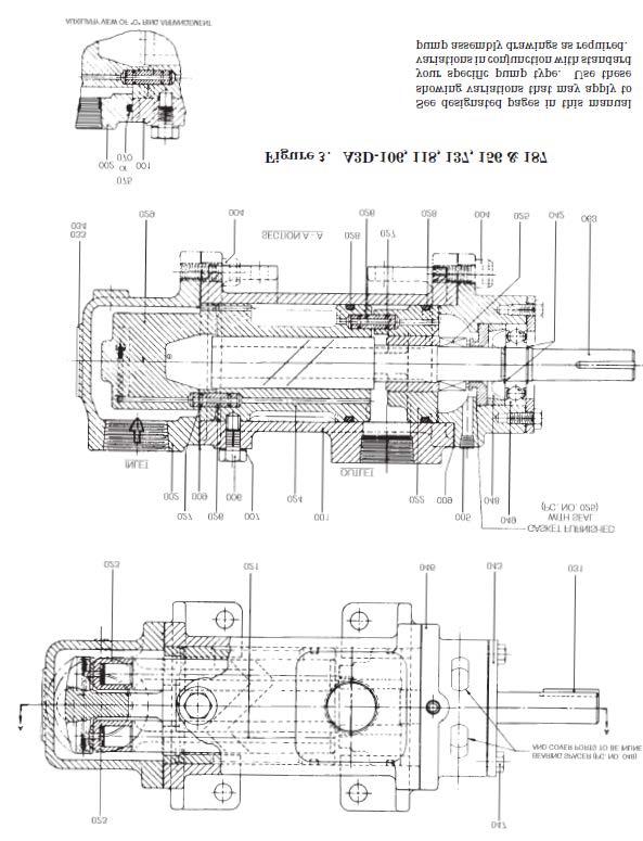
2 FOREWORD Instruction manual covers Imo Pump Series A3D pumps. Series of pumps have been designed to meet requirements for hydraulic, distillate, lubricating, residual and crude oil applications. Because of large number of operating conditions, it is necessary to have a variety of construction and material combinations to meet job requirements. Model of each pump is identified on pump nameplate. Correct use of manual requires identification of Figure(s) applicable to pump assembly and seal arrangement. Refer to Table 1, assembly drawings, Figures 3, 7, 8, 9, 10 and mechanical seal drawings, Figure 2, for applicable pump seal selection. Packing pumps are illustrated in Figures 4, 5, 6. If pump type is not specifically identifiable in manual, contact Imo Service Department with pump model and serial number for assistance Instructions given herein cover generally the operation and maintenance of subject equipment. Should any questions arise which may not be answered specifically by these instructions, they should be referred to Imo Pump for further detailed information and technical assistance. Manual cannot possibly cover every situation connected with operation, adjustment, test, overhaul and maintenance of equipment furnished. Every effort is made to prepare text of manual so that engineering and design data is transformed into most easily understood wording. Imo Pump, in furnishing this equipment and this manual, must presume that operating and maintenance personnel assigned thereto have sufficient technical knowledge and experience to apply sound safety and operational practices which may not be otherwise covered herein. In applications where Imo Pump furnished equipment is to be integrated with a process or other machinery, these instructions should be thoroughly reviewed to determine proper integration of equipment into overall plant operational procedures. On critical or dangerous equipment, provide suitable safety and emergency systems to protect personnel and property from injury due to pump malfunction. If pump handles flammable, toxic, corrosive or explosive fluids, provide for safety in event of pump leakage or malfunction. If installation, operation, and maintenance instructions are not correctly and strictly followed and observed, serious damage to pump could result. Imo Pump cannot accept responsibility for unsatisfactory performance or damage resulting from failure to comply with instructions. Table 1 SERIES A3D TYPICAL PUMP ASSEMBLY DRAWINGS MECHANICAL SEALS Rotor Size 106, 118, 137, 156, 187, 218, 250, 275, 337, 312, 350, 400 PACKING PUMPS 106, ,156, ,250,275 Figure No. 3, 7, 8, 9, Figure 1 - Definitions of Model Designators
3 X X 3D X X X X XXX X Basic Pump Modifiers A - Design Modification B - Carbide Seat Size 312 and Larger D Dampening Groove E 300 Lb. ANSI Inlet Flange F 300 Lb. ANSI Inlet Flange, Orifices Deleted From Balance Piston Housing G O-Ring Inlet Head H Special Discharge Flange L Dalic Plated Housing Pump Modifiers A Design Modification B One Piece Inboard Cover and Balance Piston Housing F Dampening Groove G Design Modification V Vertical Mount 1 st Letter Designator (Seal Design) B Crane Type 21, Buna Fitted, Std. Bearing C Crane Type 9, Teflon Fitted, Std. Bearing F Standard Packing H Crane Type 8, Teflon Fitted, Hi-Temp Bearing K No Seal, Open Bearing L Crane Type 2, Std. Bearing M Borg BXQW, Buna Standard Bearing N Borg Warner Type BX, Viton Fitted Hi-Temp Bearing R Crane S8B5 Seal, Hi-Temp. Bearing S Sealol, Viton Fitted, Hi-Temp Bearing U- Borg Seal, Hi-Temp. Bearing V Crane Type 21, Viton Fitted, Std. Bearing W Hi-Temperature Packing Z Borg Warner Type Q, Viton Fitted, Hi-Temp. Bearing Series Rotation Blank CW D- CCW P Short Lead Rotor Size Rotor Size 106, 118, 137, 156, 250, 275, 337, th Letter Designator J Carbide Seal Seat Silicon T Carbide Seal Seat Tungsten X Special Material or Const. 3 rd Letter Designator C Circular Mounting Flange J Carbide Seal Seat Silicon N Nodular Iron Casing R Inlet Clamp Ring S Steel Casing T Carbide Seal Seat Tungsten U Stellite Seal Seat X Special Material or Const. 2 nd Letter Designator C Circular Mounting Flange H Special Mounting Flange J- Carbide Seal Seat Silicon M Circular Mtd. Flange, Nodular Iron Casing N Nodular Iron Casing P Straight Thru Inlet 300 Lb. R.F. Flange R Straight Thru Inlet 150 Lb. R.F. Flange S Steel Casing T Carbide Seal Seat Tungsten X Special Material or Construction Y - Metal Bellows Seal Neoprene Type 680/BXQ NOTE: Letter designators following series designator (3D) identify mechanical seal design, construction and special features. Series designator (3D) is followed by 1, 2, 3 or 4 letter designators. Examples of determining a particular pump type from letter designators are given below. Table applies to all designators. Examples: 3DB (Crane 21 Seal) 3DBC (Crane 21 Seal, Circular Mounting Flange) 3DBCS (Crane 21 Seal, Circular Mounting Flange, Steel Casing)
4 STRUCTURAL LIMITS Operating conditions such as speed, fluid viscosity, inlet pressure, temperature, filtration, duty cycle, mounting, drive type, etc. are interrelated. Due to variable conditions, specific application limitations may vary from structural limitations. Equipment must not be operated without verification that operating requirements are within published capabilities as shown in appropriate pump brochure (available from local Imo Pump Division offices and representatives listed in Manual SRM000 Under no circumstances are the following structural limitations to be exceeded Maximum Speed (Rpm) Rotor Size Distillate Oils Lube & Seal Oil Residual & Crude Oils Type B & H Type B & H Type F Type B & H Type F to Condition Limit Minimum Viscosity 32 SSU Maximum Viscosity (figure 1) 1 st Letter Designator F 100 SSU Minimum 1 st Letter Designator B 33 SSU Min / 2500 SSU Max 1 st Letter Designator H 33 SSU Min / Max Minimum Liquid Temperature 0 F Maximum Liquid Temperature (figure 1) 1 st Letter Designator F 230 F 1 st Letter Designator B 180 F 1 st Letter Designator H 220 F 75 psig for sizes137 thru 250 Maximum Inlet Pressure 50 psig for sizes 275 and larger 10 Psig for Packing Pumps Maximum Discharge Pressure (Continuous Duty) 500 psig Filtration Refer to General Instruction Manual, SRM000 Drive Direct or Belt For Seal Pumps Direct Only for Packing Pumps Mounting Mounted in any attitude ORDERING INSTRUCTIONS All correspondence pertaining to renewal parts for Series A3D pumps must refer to this instruction manual number and should be addressed to the nearest Imo Pump Division representative listed in SRM The following directions should be followed for renewal part orders: 1. Give number of this instruction manual. 2. Give pump type and serial number of pump for which part(s) is ordered. 3. Give figure number(s) on which pump type and sealing design part(s) is shown. 4. Give part number(s) for necessary part(s).
5 Table 4 LIST OF MATERIALS (FIGURES 3 THROUGH 11) ITEM PART DESCRIPTION ITEM PART DESCRIPTION 001 Case 036 Tube 002 Inlet Head 036 Lockwasher 003 Packing Box End Cover 037 Spacer 004 (3) Bolt or Capscrew 038 (1) O-ring (Figure 16) 005 Plug 040 Spacer 006 (2) Stop Pin 042 (2) Truarc Ring (2) 007 (1) Dyna Seal 043 Retainer 008 (2) Retaining Ring 043 Plug 008 Inboard Cover (Figure 16) 044 (2) Power Rotor 009 (1) Gasket (2) 045 Balance Piston Housing 010 (2) Retainer Plate 046 Inboard Cover 011 Capscrew (4) 047 Bolt (4) 012 Spring Pin (2) 048 (2) Spacer or Seat Adapter 013 Cotter Pin 049 (1) Ball Bearing 014 Packing Gland Screw (2) 063 (2) Power Rotor 014 Spacer (Figure 16) 064 Plug 015 Washer (2) 067 Plug 015 (1) Ball Bearing (Figure 16) 068 Nipple 016 Nut (2) 069 Coupling 016 Bearing Retainer (Figure 16) 070 (1) O-ring (Figure 10) 017 (1) Packing 070 Elbow 017 Bolt (4) Figure 16) 071 Tubing 018 Packing Gland 072 Plug 019 (2) Power Rotor 073 Plug 020 (1) Truarc Ring (2) 074 Elbow 021 (2) Idler Rotor (2) 074 Nameplate 022 Oil Balance Tube External 075 O-ring (Figure 10) 022 (2) Balance Piston Housing 075 Plug 023 (2) Idler Balance Piston Housing (2) 075 Nipple 023 Spacer (2) (Figure 16) 076 (1) O-ring 024 (2) Rotor Housing 076 Tee 025 (1) Seal 077 Nipple 026 (2) Oil Balance Tube (2) 078 (2) Check Valve 026 Thrust Plate (Figure 16) 079 Elbow 027 (1) O-ring (4) 080 Elbow 027 Gasket 080 Plug 028 (1) O-ring (2) 081 (1) Gasket 029 (2) Thrust Cage 081 Tubing 029 Bolt (2) (Figure 16) 084 Spacer 029 Thrust Plate (Figures 18 & 19) 086 (2) Bushing 030 Lockwasher (2) (Figure 16) 090 Spacer 031 Key 091 Washer (4) 032 (2) Relief Valve 091 Spacer 033 Nameplate 092 (1) Gasket 034 Drive Screw (2) 092 Spacer (Figure 22) 035 Plug 092 Washer (4) Quantities are one (1) except when noted in parentheses after description. Items marked (1) are minor kit items. Items marked (2) are major kit items. This is a General Parts List. Refer to specific rotor size for appropriate parts that apply specifically to your pump. When an item number applies to more than one part by noun name, use part as indicated on proper assembly figure for your pump.
6 Note: For disassembly of Mechanical Seal and Ball Bearing Only, follow steps 1, 2, 3, 9, 10, 11 and 13. For Reassembly of Mechanical Seal and Ball Bearing Only, Follow steps 8, 9, 10 and 11. DISASSEMBLY AND ASSEMBLY PROCEDURES (MECHANICAL SEAL PUMPS) WARNING To prevent personnel/equipment injury, power supply to pump driver must be disconnected or positively tagged out prior to starting any disassembly procedure. FIGURE 2 - MECHANICAL SEAL TYPES
7 Disassembly Procedures (Figures 3, 7, 8, 9) WARNING When inspecting/servicing shaft seal and/or bearing, power rotor can be removed as a subassembly with these components installed. Remove four (4) bearing retainer plate bolts and retainer plate, and then remove power rotor sub-assembly. If for any reason pump is disassembled further than this, it is possible idler rotor balance piston housings may fall off. These idler rotor balance piston housings MUST be properly in place at reassembly. If idler rotor balance piston housings are not properly installed on idler rotors, pump WILL experience catastrophic failure. Figures listed are basic pump assembly figures. For variations that may apply to your pump, see figure 16 for seal installation variations. 1. Close off suction and discharge piping to pump and disconnect piping. 2. If applicable, remove tubing (071) and, if applicable, check valve (078). 3. Remove inlet drain plugs and drain unit. Remove pump from driver, coupling and mounting bracket. Remove coupling hub and key (031). 4. Remove inlet capscrews (004), inlet head (002) and gasket (009) or O-ring (070 or 075) as applicable. 5. (Figures 3, 7 and 8) Remove thrust cage (029). Remove oil balance tube (026) with O-rings (027) from either thrust cage (029) or rotor housing (024). Remove O-rings (027) from oil balance tube (026). 6. (Figures 3, 7 and 8) Remove idler balance piston housings (023) from idler rotors (021), and remove idler rotors (021) by unscrewing idlers from rotor housings (024). 7. (Figures 9) Remove bolts (029 or 053) with lockwashers (030 or 052). Remove thrust plate (026 or 029) and spacers (023 or 051). Remove spacer (040 or 050) from case (001). 8. (Figures 9) Remove idler rotors (021) from housing (024) bores by unscrewing idler rotors from threads of power rotor. 9. Remove bolts (047 or 017) and bearing retainer (043 or 016). 10. Remove power rotor (044 or 063) assembly from case (001). NOTE: Removal of power rotor (044 or 063) will also remove Truarc rings (042), ball bearing (049), spacer (048 or 014), sleeve (037 or 038) if applicable and mechanical seal (025). NOTE: Balance piston furnished as part of power rotor (044 or 063) and is not serviced separately. 11. Remove gasket from bore of inboard cover (046 or 008). 12. Remove inboard cover capscrews (004) and inboard cover (046 or 008) from case (001). NOTE: Removal of inboard cover (046) may include removal of O-ring (028) and bushing (086). Bushing (086) is locked to inboard cover (046) with Loctite retaining compound and should not be removed unless replacement is necessary. 13. Remove gasket (009) from case (001).
8 14. Remove balance piston housing (022 or 045) with O-ring (028) from case (001). Remove O-ring (028) from balance piston housing (022 or 045). 15. Remove oil balance tube (026 or 036) with O-rings (027 or 038) from rotor housing (024) or balance piston housing (022 or 045) or inboard cover (046 or 008). Remove O-rings (027 or 038) form oil balance tube (026 or 036). 16. Remove stop pin (006) and Dyna Seal (007) from case (001). Remove rotor housing (024) with O-ring (028) from case (001). Remove O-ring (028) from groove of rotor housing (024). 17. Disassemble power rotor (044 or 063), removed in Step 10 as follows: (Figures 3, 7, 8, 9) Remove outer truarc ring (042). Press ball bearing (049) off power rotor (063). Remove inner truarc ring (042). (Figures 3, 7, 8, 9) If seal is J seat type, remove spacer (048 or 014) and mechanical seal stationary seat. If seal is O-ring type, remove seal seat adapter (048 or 014) with stationary seat from power rotor (044 or 063). Remove stationary seat from seal seat adapter (048 or 014) NOTE: Refer to Figure 2 for Mechanical Seal Types for proper disassembly. (Figures 3, 7, 8, 9) Remove mechanical seal rotating assembly from power rotor (044 or 063). NOTE: Refer to Figure 2 for Mechanical Seal Types for proper disassembly. (Figures 7, 8, 9) Remove sleeve (038 or 037) from power rotor (044 or 063). Assembly Procedures (Figures 3, 7, 8, 9 and 11) NOTE: Prior to pump assembly, all parts should be cleaned and inspected for nicks and burrs. Replace all worn or damaged parts. Imo Pump Division recommends automatic replacement of O-rings (027, 028 and 038), gaskets (009), Dyna seal (007), ball bearing (049 or 015) and mechanical seal (025) when these parts are disturbed from their previously installed position. Refer to pump assembly drawings (Figures 3, 7, 8, 9), and List of Material (Table 4), during assembly. Coat all parts with light lubricating oil to assist in assembly. Assembly procedures for all A3D pumps equipped with mechanical seals are identical except when specifically noted. WARNING When inspecting/servicing shaft seal and/or bearing, power rotor can be removed as a subassembly with these components installed. Remove four (4) bearing retainer plate bolts and retainer plate, and then remove power rotor sub-assembly. If for any reason pump is disassembled further than this, it is possible idler rotor balance piston housings may fall off. These idler rotor balance piston housings MUST be properly in place at reassembly. If idler rotor balance piston housings are not properly installed on idler rotors, pump WILL experience catastrophic failure. Figures 3, 7, 8, 9 are basic pump assembly figures. For variations that may apply to your pump, see Figure 10 for seal installation variations. 1. Install O-ring (028) in groove of rotor housing (024). (Figures 3, 7, 8, 9 and 11) Install O-rings (027) on oil balance tube (026), and install oil balance tube (026) in suction end of rotor housing (024). 2. (Figures 3, 7, 8 and 11) Install O-rings (027 or 038) on oil balance tube (026 or 036), and install oil balance tube (026 or 036) in discharge end of rotor housing (024).
9 3. Install assembled rotor housing (024) in case (001), aligning housing (024) to receive stop pin (006). Install stop pin (006) with Dyna seal (007) in case (001). 4. (Figures 3, 7, 8, 9 and 11) Install O-ring (028) in groove of balance piston housing (022 or 045), and install balance piston housing (022 or 045) in case (001), ensuring that bore of balance piston housing (022 or 045) engages oil balance tube (026 or 036) installed in rotor housing (024). 5. (Figures 3, 7, 8, 9) Install gasket (009) on case (001). 6. Install inboard cover (046 or 008) on case (001) using capscrews (004 or 093). Tighten capscrews (004 or 093) to proper torque value listed in Table 2. NOTE: If applicable, lockwashers (092) will be installed with bolts (004). Table 2 TORQUE VALUES MECHANICAL SEAL PUMPS Rotor Size IDP# Torque IDP# Torque ± 2 lb-ft ± 5 lb-in ± 2 lb-ft ± 2 lb-ft ± 2 lb-ft ± 2 lb-ft ± 2 lb-ft ± 2 lb-ft ± 2 lb-ft ± 2 lb-ft ± 5 lb-ft ± 2 lb-ft ± 10 lb-ft ± 2 lb-ft ± 2 lb-ft ± 2 lb-ft ± 2 lb-ft ± 2 lb-ft ± 5 lb-ft ± 2 lb-ft ± 5 lb-ft ± 2 lb-ft ± 5 lb-ft ± 2 lb-ft 8. Assemble power rotor (044 or 063) as follows: (Figures 7, 8, 9) Install sleeve (038) on power rotor (044 or 063) shaft next to piston. (Figures 3, 7, 8, 9) Install mechanical seal (025) rotating assembly on power rotor (044 or 063) shaft. Tighten set screw if applicable. NOTE: Refer to Figure 2 for Mechanical Seal Types for proper assembly. (Figures 6, 10 and 11) If seal is a J seat design Install stationary seat on power rotor (063 or 044) shaft. Then install spacer (014 or 048). If seal stationary seat is an O-ring design, be sure O-ring is installed on seal seat and then install seat in seal seat adapter (048 or 014). Be sure groove in back of stationary seat mates with pin in seal seat adapter (48 or 14) NOTE: Refer to Figure 2 for Mechanical Seal Types for proper assembly (Figures 3, 7, 8, 9) Install inner truarc ring (042) in groove of power rotor. Press ball bearing (049) on power rotor (063) shaft, pressing only on inner race of bearing. Install outer truarc ring (042) in groove of power rotor shaft. 9. (Figures 3, 7, 8, 9) Install gasket or O-ring, based on mechanical seal design, in mechanical seal bore of inboard cover (046 or 008). 10. Install assembled power rotor (044 or 063) in inboard cover (046 or 008), centering each part as it enters pump case (001).
10 11. Install bearing retainer (043 or 016) using bolts (047 or 017). Tighten bolts (047 or 017) to proper torque value listed in Table Install idler rotors (021) in idler bores of rotor housing (024) by engaging threads of idler rotors with threads of power rotor (044 or 063) and rotating idler rotors (021) while inserting them into rotor housing (024) bores. 13. (Figures 3, 7, 8) Install idler balance piston housings (023) on idler rotors (021). 14. (Figures 3, 7, 8) Install thrust cage (029), ensuring that bore of thrust cage (029) engages oil balance tube (026) installed in rotor housing. 15. (Figure 9) Install spacer (040 or 050) in housing (001). Install spacers (023 or 051) and thrust plate (026 or 029) on rotor housing (024) using bolts (029 or 053) and lockwashers (030 or 052). Tighten bolts (029 or 053). 16. Install gasket (009) and inlet head (002) on case (001) using bolts or capscrews (004). Tighten bolts or capscrews (004) to proper torque value listed in Table Install drain plugs which were removed during pump disassembly. 18. Install key (031) and coupling hub on power rotor (044 or 063) shaft. DISASSEMBLY AND ASSEMBLY PROCEDURES (PACKING PUMPS) Disassembly Procedures (Figures 4, 5 and 6) NOTE: Refer to pump assembly drawings, Figures 4 through 6, during pump disassembly. Disassembly procedures are identical for Figures 4 through 6 unless specifically noted. 1. Close off suction and discharge piping to pump and disconnect piping. 2. (Figures 5 and 6) Remove tubing (081) from pump, ensuring that tubing (081) is not bent or flattened. Remove drain plugs (005 and 080). 3. Remove pump from driver, coupling and mounting bracket. Remove coupling hub and key (031). 4. Remove packing gland nuts (016) with washers (015) and remove packing gland (018). 5. Using a packing puller or sharp pointed brass or copper rod, remove packing (017). 6. Remove bolts or capscrews (004), packing box end cover (003) and gasket (009). 7. Remove bolts or capscrews (004), inlet head (002) and gasket (009) from case (001). 8. Remove thrust cage (029). 9. Remove idler balance piston housings (023) and idler rotors (021). NOTE: Remove idler rotors (021) by unscrewing idler rotors from housing (024) bores. 10. (Figures 5 and 6) Remove spacer (090). 11. Remove cap screws (011) and retainer plate (010).
11 12. (Figure 4) Remove retaining ring (008). 13. Remove power rotor (019 or 063). Removal of power rotor (019 or 063) will also remove balance piston housing (022) with O-ring (028) and oil balance tube (026). NOTE: Balance piston (020) furnished as part of power rotor (019 or 063) and is not serviced separately. 14. Remove balance piston housing (022) from power rotor (019 or 063). Remove O-ring (028) and oil balance tube (026) from balance piston housing (022). 15. (Figure 4) Remove O-ring (027) from oil balance tube (026), and remove relief valve (032 from balance piston housing (022). 16. Remove stop pin (006) with Dyna seal (007) from case (001). 17. Remove rotor housing (024) with O-ring (028) and oil balance tube (026) from suction end of pump case ( Remove O-ring (028) and oil balance tube (026) from rotor housing (024). Remove O-rings (027) form grooves of oil balance tube (026). Assembly Procedures (Figures 4 through 6) NOTE: Prior to assembly of pump, all parts should be cleaned and inspected for nicks and burrs. Replace all worn or damaged parts. Imo Pump Division recommends automatic replacement of O-rings (027 and 028), gaskets (009), Dyna seal (007) and packing (017) when these parts are disturbed from their previously installed position. Refer to pump assembly drawings, Figures 8, 9 and 10, and List of Material, Table 3, during pump assembly. Coat all parts with light lubricating oil to assist in assembly. Assembly procedures for Figures 8 through 10 are identical unless specifically noted. 1. Install O-ring (028) in groove of rotor housing (024), and install rotor housing (024) in suction end of pump case (001), ensuring that bore in rotor housing (024) is aligned with stop pin (006) bore of pump case (001). 2. Install stop in (006) with Dyna seal (007) in pump case (001) and rotor housing (024). 3 Install O-rings (027) in grooves of oil balance tube (026) and install oil balance tube (026) in bore of suction end of rotor housing (024). 4. Install O-ring (028) in groove of balance piston housing (022), and install balance piston housing (022) on power rotor (019 or 063) shaft. 5. (Figure 4) Install relief valve (032) in balance piston housing (022). Install O-rings (027) in grooves of oil balance tube (026). 6. Install oil balance tube (026) in bore of balance piston housing (022). 7. Install power rotor (019 or 063) assembly in bore case (001), ensuring that oil balance tube (026) engages bore of rotor housing (024). 8. (Figure 4) Install retaining ring (008) in groove of case (001). 9. Install retainer plate (010) using capscrews (011). 10. (Figures 5 and 8) Install spacer (090).
12 11. Install gasket (009) and packing box end cover (003) using bolts or capscrews (004). Tighten bolts or capscrews (004) to proper torque valve listed in Table 3. Table 3 TORQUE VALVES PACKING PUMPS Rotor Size IDP# Torque 106 (Installed in inlet) 4 43 ± 2 lb-ft 106 (Installed in packing box cover) 4 24 ± 2 lb-ft 118 (Installed in inlet) 4 49 ± 2 lb-ft 118 (Installed in packing box cover) 4 26 ± 2 lb-ft ± 2 lb-ft ± 2 lb-ft ± 2 lb-ft ± 2 lb-ft 12. Install packing (017) rings in packing bore of packing box end cover (003). Joints of packing (017) ring to be staggered and hard and soft rings alternately inserted, beginning with hard ring of packing. 13. Install packing gland (018). Install washer (015) and nut (016) on packing gland screw (014) and tighten nut (016) hand tight. 14. Install idler rotors (021) into rotor housing (024) idler rotor bores by engaging threads of idler rotors with threads of power rotor (019 or 063) and rotating idler rotors (021) while inserting them into rotor housing (024). 15. Install idler balance piston housings (023) on idler rotors (021). 16. Install thrust cage (029), ensuring that bore in thrust cage (029) engages oil balance tube (026) installed in rotor housing (024). 17. Install gasket (009) and inlet head (002) on case (001) using bolts or capscrews (004). Tighten bolts or capscrews (004) to proper torque valve listed in Table Install key (031) and coupling hub on power rotor (019 or 063) shaft. 19. Install drain plugs (005 or 080). 20. (Figures 5 and 6) Install tubing (081) and fittings in proper position. 21. Connect pump to mounting bracket and coupling. Align pump with driver as described in Manual CA-1. Caution When starting pump, adjust packing seepage to allow no more than eight (8) drops per minute. DO NOT over-tighten packing. Seepage from packing gland provides cooling and lubrication of packing
13
14
15
16
17 Figure 7. A3D-218, 250, 275, & 312
18
19
20
21
289-6511 Email: imo.pump@colfaxcorp.com Web: www.imo-pump.")
22 Colfax Fluid Handling 1710 Airport Road PO Box 5020 Monroe, NC USA Tel: 1+ (704) Web: Colfax Fluid Handling all rights reserved.
INSTRUCTION MANUAL AND PARTS LIST FOR PG/RG3D-275 SERIES PUMPS (Idler Cup and Hydrostatic Thrust Designs)
") TM INSTRUCTION MANUAL AND PARTS LIST FOR PG/RG3D-275 SERIES PUMPS (Idler Cup and Hydrostatic Thrust Designs) WARNING This Instruction Manual and General Instructions Manual, CA-1, should be read thoroughly
TM INSTRUCTION MANUAL AND PARTS LIST FOR PG/RG3D-275 SERIES PUMPS (Idler Cup and Hydrostatic Thrust Designs) WARNING This Instruction Manual and General Instructions Manual, CA-1, should be read thoroughly
PRODUCT SERVICE MANUAL. BK6DHZ(C)-250, 275, 312 and 400 PUMPS
-250, 275, 312 and 400 PUMPS") PRODUCT SERVICE MANUAL BK6DHZ(C)-250, 275, 312 and 400 PUMPS WARNING This manual, and the GENERAL INSTRUCTION MANUAL, SRM00046, should be read thoroughly prior to pump installation, operation or maintenance.
PRODUCT SERVICE MANUAL BK6DHZ(C)-250, 275, 312 and 400 PUMPS WARNING This manual, and the GENERAL INSTRUCTION MANUAL, SRM00046, should be read thoroughly prior to pump installation, operation or maintenance.
Product Service Manual For DLH12DHT SERIES PUMPS
 Product Service Manual For DLH12DHT SERIES PUMPS Pump Size Bill of Material Assembly Drawing 275 3217 / 568 - DLH12DHTX-275 Figure 3 312 3220 / 561 - DLH12DHT 312 Figure 3 3220 / 567 - DLH12DHT - 312 P
PRODUCT SERVICE MANUAL FOR BK12DHZ PUMPS
 PRODUCT SERVICE MANUAL FOR BK12DHZ PUMPS WARNING This manual, and the GENERAL INSTRUCTION MANUAL SRM00046, should be read thoroughly prior to pump installation, operation or maintenance. Manual No. SRM00095
INSTRUCTION MANUAL AND PARTS LIST FOR PG/RG3D_-187, 218, 250 and 312 SERIES PUMPS
 INSTRUCTION MANUAL AND PARTS LIST FOR PG/RG3D_-187, 218, 250 and 312 SERIES PUMPS WARNING This Instruction Manual and General Instructions Manual, CA-1, should be read thoroughly prior to pump installation,
PRODUCT SERVICE MANUAL SERIES 4U AND 6U SERIES 4T AND 6T ROTOR SIZES
 PRODUCT SERVICE MANUAL SERIES 4U AND 6U SERIES 4T AND 6T ROTOR SIZES 118-250 WARNING The IMO General Installation Operation, Maintenance and Troubleshooting Manual, (No. SRM00046), this manual, and associated
PRODUCT SERVICE MANUAL FOR. F312XICR-312_, 325_, 400_ and 437_ Pumps. For Solar Turbines
 PRODUCT SERVICE MANUAL FOR F312XICR-312_, 325_, 400_ and 437_ Pumps For Solar Turbines WARNING This manual and the General Installation, Operation, Maintenance and Troubleshooting Manual (SRM00046) should
K12DHZ-312P Pump PRODUCT SERVICE MANUAL. Imo Part Number / BOM # 3220/523
 K12DHZ-312P Pump PRODUCT SERVICE MANUAL Imo Part Number / BOM # 3220/523 WARNING This manual and the General Installation, Operation, Maintenance and Troubleshooting Manual (SRM00046) should be read in
INSTRUCTION MANUAL AND PARTS LIST FOR SERIES 8L-630J AND 630M WARNING
 INSTRUCTION MANUAL AND PARTS LIST FOR SERIES 8L-630J AND 630M WARNING READ CA-l AND TIDS INSTRUCTION MANUAL PRIOR TO INSTALLATION, OPERATION OR MAINTENANCE WARNING This Instruction Manual and General Instructions
PRODUCT SERVICE MANUAL FOR _G3D -350 and 400 SERIES PUMPS (Idler Cup and Hydrostatic Thrust Designs)
") PRODUCT SERVICE MANUAL FOR _G3D -350 and 400 SERIES PUMPS (Idler Cup and Hydrostatic Thrust Designs) WARNING The Imo General Installation Operation, Maintenance, and Troubleshooting Manual, (No. SRM00046),
PRODUCT SERVICE MANUAL FOR _G3D -350 and 400 SERIES PUMPS (Idler Cup and Hydrostatic Thrust Designs) WARNING The Imo General Installation Operation, Maintenance, and Troubleshooting Manual, (No. SRM00046),
PRODUCT SERVICE MANUAL
 PRODUCT SERVICE MANUAL FOR AM322ICX-325AE, 350AN and 400A PUMPS WARNING This Special Instruction Manual and General Instructions Manual, SRM00046, should be read thoroughly prior to pump installation,
INSTRUCTION MANUAL AND PARTS LIST FOR 3E CANNED MOTOR PUMPS
 TM INSTRUCTION MANUAL AND PARTS LIST FOR 3E CANNED MOTOR PUMPS WARNING This Special Instruction Manual and General Instructions Manual, CA-1, should be read thoroughly prior to pump installation, operation
PRODUCT SERVICE MANUAL For G6D-187, 218, 250, 275 and 312 PUMPS
 PRODUCT SERVICE MANUAL For G6D-187, 218, 250, 5 and 312 PUMPS WARNING This Instruction Manual and General Instructions Manual, SRM00046, should be read thoroughly prior to pump service, installation, operation
Instruction Manual and Parts List (G323FHF 630M) with Flow Serve Type Q Seal
 with Flow Serve Type Q Seal") TM Instruction Manual and Parts List (G323FHF 630M) with Flow Serve Type Q Seal WARNING This Instruction Manual and General Instructions Manual, CA-1, should be read thoroughly prior to pump installation,
TM Instruction Manual and Parts List (G323FHF 630M) with Flow Serve Type Q Seal WARNING This Instruction Manual and General Instructions Manual, CA-1, should be read thoroughly prior to pump installation,
INSTRUCTION MANUAL AND PARTS LIST FOR. (A)E3LB(C)(K)-187, -200, and -250 SERIES PUMPS
E3LB(C)(K)-187, -200, and -250 SERIES PUMPS") INSTRUCTION MANUAL AND PARTS LIST FOR (A)E3LB(C)(K)-187, -200, and -250 SERIES PUMPS WARNING This Manual and GENERAL INSTRUCTIONS MANUAL, SRM00046, should be read thoroughly prior to pump installation,
INSTRUCTION MANUAL AND PARTS LIST FOR (A)E3LB(C)(K)-187, -200, and -250 SERIES PUMPS WARNING This Manual and GENERAL INSTRUCTIONS MANUAL, SRM00046, should be read thoroughly prior to pump installation,
Instruction Manual & Parts List For H/G323FXFSX-500_ & 800_ Pumps With Flowserve Type BX Cartridge Seal
 TM Instruction Manual & Parts List For H/G323FXFSX-500_ & 800_ Pumps With Flowserve Type BX Cartridge Seal WARNING This Special Instruction Manual and General Instructions Manual, CA-1, should be read
Product Service Manual For AA3G Series Pumps Size 187 Through 250
 Product Service Manual For AA3G Series Pumps Size 187 Through 250 WARNING The IMO General Installation Operation, Maintenance and Troubleshooting Manual, (No. SRM00046), this manual, and associated component
INSTRUCTION MANUAL AND PARTS LIST FOR 3SIC AND 4SIC SERIES PUMPS
 TM INSTRUCTION MANUAL AND PARTS LIST FOR 3SIC AND 4SIC SERIES PUMPS WARNING This manual, and General Instructions Manual, CA-1 should be read thoroughly prior to pump installation, operation or maintenance.
Instruction Manual and Parts List For G/H323F 550/550J/550M Pumps with Crane Type 2, 8-1, FS QWD and FS Q Non-Cartridge Seals
 TM Instruction Manual and Parts List For G/H323F 550/550J/550M Pumps with Crane Type 2, 8-1, FS QWD and FS Q Non-Cartridge Seals WARNING This Instruction Manual and General Instructions Manual, CA-1, should
SERIES G3DB/AG3DB ELEVATOR
 TM INSTRUCTIONS AND PARTS LIST SERIES G3DB/AG3DB ELEVATOR WARNING This manual, and GENERAL INSTRUCTIONS MANUAL, CA-1, should be read thoroughly prior to pump installation, operation or maintenance. SRM00059
INSTRUCTION MANUAL AND PARTS LIST FOR 3G SERIES PUMPS SIZES 95 THROUGH 162
 TM INSTRUCTION MANUAL AND PARTS LIST FOR 3G SERIES PUMPS SIZES 95 THROUGH 162 This instruction manual is now identified as SRM00020 WARNING This Special Instruction Manual and General Instructions Manual,
PRODUCT SERVICE MANUAL FOR E12L SERIES PUMPS
 PRODUCT SERVICE MANUAL FOR E12L SERIES PUMPS WARNING The Imo General Installation, Operation, Maintenance, and Troubleshooting Manual, (No. SRM00046), along with this manual and all other component manuals
CFHN SERIES PRODUCT SERVICE MANUAL
 CFHN SERIES PRODUCT SERVICE MANUAL Metric standards apply for all pumps covered by this manual with regard to Mounting dimensions, external connections, bolts, bolt threads, plugs and bearings. WARNING
PRODUCT SERVICE MANUAL FOR CIG Lip Seal Double Pumps
 PRODUCT SERVICE MANUAL FOR CIG Lip Seal Double Pumps WARNING The Imo General Installation Operation, Maintenance, and Troubleshooting Manual, (No. SRM00046), as well as all other component manuals supplied
PRODUCT SERVICE MANUAL FOR CIG Lip Seal & Weep Hole Design Single Pump
 PRODUCT SERVICE MANUAL FOR CIG Lip Seal & Weep Hole Design Single Pump WARNING The Imo General Installation Operation, Maintenance, and Troubleshooting Manual, (No. SRM00046), as well as all other component
AA2BIC SERIES PRODUCT SERVICE MANUAL
 TM AA2BIC SERIES PRODUCT SERVICE MANUAL Metric standards apply for all pumps covered by this manual with regard to mounting dimensions, external connections, bolts, bolt threads, plugs and bearings. WARNING
8L SERIES THREE SCREW PUMPS
 TM 8L SERIES THREE SCREW PUMPS The reliable pump people ROTARY SCREW PUMPS Performance Shown at 1500 PSID (103 BAR), 200 SSU (43 CST) 60 HZ: 870 1150 1750 50 HZ: 960 1450 1200 1100 630M 40 250 1000 900
PRODUCT SERVICE MANUAL FOR C324AXFX-250/12005 PUMP
 PRODUCT SERVICE MANUAL FOR C324AXFX-250/12005 PUMP WARNING This Instruction Manual and General Instructions Manual, SRM00046, should be read thoroughly prior to pump installation, operation or maintenance
PRODUCT SERVICE MANUAL FOR C324AXFS-250/12004 PUMP
 PRODUCT SERVICE MANUAL FOR C324AXFS-250/12004 PUMP WARNING This Instruction Manual and General Instructions Manual, SRM00046, should be read thoroughly prior to pump installation, operation or maintenance
EMTEC Series 3-Screw
 EMTEC Series 3-Screw Coolant and Emulsion Pumps The reliable pump people Rotary Screw Pumps Performance Shown at 1.8 cst, 3500 RPM Differential Pressure PSI 20-38 20-46 20-56 40-38 40-46 80-36 80-46 140-39
OPERATION MANUAL INTERNAL GEAR PUMP. Models: NG-H, NG-HL, NG-K, NG-KK, NG-L, NG-LQ, NG-LL, NG-LS, NG-Q, NG-QS. Tel: Fax:
 OPERATION MANUAL INTERNAL GEAR PUMP Models: NG-H, NG-HL, NG-K, NG-KK, NG-L, NG-LQ, NG-LL, NG-LS, NG-Q, NG-QS. 1 Contents Pump Designation System Maintenance Thrust bearing adjustment Pressure Relief Valve
PRODUCT OBSOLETED 1Q16
 TECHNICAL SERVICE MANUAL HEAVY DUTY STEEL EXTERNAL MOUNTED PUMPS SERIES 123 AND 4123 SIZES H-LL SECTION TSM 151.1 PAGE 1 OF 13 ISSUE C CONTENTS Introduction 1 Special Information 2 Maintenance 3 Packed
TECHNICAL SERVICE MANUAL
 TECHNICAL SERVICE MANUAL ABRASIVE LIQUID HEAVY-DUTY BRACKET MOUNTED PUMPS SERIES 4625 SIZES H - M SECTION TSM 410.2 PAGE 1 of 10 ISSUE C CONTENTS Introduction....................... 1 Special Information...................
LEVEL CONTROLS 313 IOM
 LEVEL CONTROLS 313 IOM 313 OVERFLOW TRAP INSTALLATION, OPERATION & MAINTENANCE INSTRUCTIONS TABLE OF CONTENTS Overview...Cover General Information...Cover Installation...4 Operation...4 Maintenance...4
CONTENTS. VIKING PUMP, INC. A Unit of IDEX Corporation Cedar Falls, IA USA SECTION TSM 710.1
 TECHNICAL SERVICE MANUAL industrial heavy duty motor speed pumps SERIES 4076 AND 4176 SIZES hle, ate and ale SECTION TSM 710.1 PAGE 1 of 8 ISSUE B CONTENTS Introduction....................... 1 Safety
INSTRUCTION MANUAL INTERNAL GEAR PUMP TITAN G-4124A SERIES=> FLANGED TITAN G-124A SERIES => FLANGED MODELS:
 INSTRUCTION MANUAL INTERNAL GEAR PUMP TITAN G-4124A SERIES=> FLANGED TITAN G-124A SERIES => FLANGED MODELS: G-H, G-HL, G-K, G-KK, G-L, G-LQ, G-LL, GLS, G-Q, G-QS 1 Contents Maintenance Thrust bearing adjustment
OPERATION MANUAL 1 POLYPROPYLENE PUMP DURA-FLO TM AIR DISTRIBUTION SYSTEM
 OPERATION MANUAL 1 POLYPROPYLENE PUMP DURA-FLO TM AIR DISTRIBUTION SYSTEM CAUTIONS - READ FIRST CAUTION: Do not apply compressed air to the exhaust port pump will not function. CAUTION: Do not exceed 82
TECHNICAL SERVICE MANUAL
 Electronic copies of the most current TSM issue can be found on the Viking Pump website at www.vikingpump.com TECHNICAL SERVICE MANUAL HEAVY-DUTY Stainless steel BRACKET MOUNTED PUMPS SERIES 127 AND 4127
TECHNICAL SERVICE MANUAL
 Electronic copies of the most current TSM issue can be found on the Viking Pump website at www.vikingpump.com TECHNICAL SERVICE MANUAL industrial heavy duty motor speed pumps SERIES 4076 AND 4176 SIZES
6200 Series. Specifications. Fluid End Power End Models 6211, 6212, 6221, & 6222 Models 6241 & 6242 Part Material Part Material Part Material
 5.2018.12.i 6200 Series Specifications The Flomore 6200 Series Pump line consists of a series of basic pump options all developed from a modular power unit. All units are pneumatically driven positive
PRODUCT OBSOLETED 4Q16
 Electronic copies of the most current TSM issue can be found on the Viking Pump website at www.vikingpump.com TECHNICAL SERVICE MANUAL SECTION TSM 141.1 HEAVY-DUTY BRACKET MOUNTED PUMPS PAGE 1 of 16 SERIES
Smith Meter PD Meter Meter, PD Series, K12- S1, S3, S5, S6, and S7
 Smith Meter PD Meter Meter, PD Series, K12- S1, S3, S5, S6, and S7 Parts List Bulletin PO01018 Issue/Rev 0.1 (7/13) S1, S3, S5 S6, S7 Item Description Qty. K12-S1 K12-S5 K12-S7 Page 2 SS01018 Issue/Rev.
TYPE 200 IOM - VACUUM BREAKER
 TYPE 200 IOM - VACUUM BREAKER INSTALLATION, OPERATION & MAINTENANCE INSTRUCTIONS TYPE 200 VACUUM BREAKER TABLE OF CONTENTS Overview... COVER General Information... COVER Installation... 4 Operation...
TECHNICAL SERVICE MANUAL
 TECHNICAL SERVICE MANUAL HEAVY-DUTY bracket mounted PUMPS SERIES 4193 AND 493 SIZES GG - AL SECTION TSM 154 PAGE 1 of 10 ISSUE C CONTENTS Introduction....................... 1 Special Information...................
TRITEC SERIES THREE SCREW PUMPS
 TM TRITEC SERIES THREE SCREW PUMPS The reliable pump people ROTARY SCREW PUMPS Performance Shown at 3500 RPM, 1.0 Centistokes DIFFERENTIAL PRESSURE, bar 280 0 20 40 60 80 1100 260 1000 440-46 Low Viscosity
Meter, PD Series, K12-S1, S3, S5, S6 and S7
 PARTS LIST Meter, PD Series, K12-S1, S3, S5, S6 and S7 Bulletin PO01018 Issue/Rev. 0.4 (3/18) S1, S3, S5 S6, S7 Item Description Qty. K12-S1 K12-S5 K12-S7 2 Bulletin PO01018 Issue/Rev. 0.4 (3/18) Item
ACD6. Std Line. Product Description. Max differential pressure: 7 bar Circulation, lubrication and transfer ACD GB
 ACD6 Std Line Product Description Flow volume: 10-42 l/min Max differential pressure: 7 bar Applications: Circulation, lubrication and transfer 1. Applications 1.1 Functionality The ACD pumps come in two
TYPE 5625/5625P DUAL METAL BELLOWS CARTRIDGE SEAL
 Foreword TYPE 5625/5625P These instructions are provided to familiarize the user with the seal and its designated use. The instructions must be read and applied whenever work is done on the seal, and must
CP-1, CP-2, CP-2L & CPD-2 Series Overhaul
 Replacement of Mechanical Seals for CM, CMU, CS and CSU Series Pumps Installation Instructions Form No. F-1031 Section 5013 Issue Date 03/01/85 Rev. Date 02/08/11 CP-1, CP-2, CP-2L & CPD-2 Series Overhaul
OPERATION MANUAL 2 POLYPROPYLENE PUMP DURA-FLO TM AIR DISTRIBUTION SYSTEM
 OPERATION MANUAL 2 POLYPROPYLENE PUMP DURA-FLO TM AIR DISTRIBUTION SYSTEM CAUTIONS - READ FIRST CAUTION: Do not apply compressed air to the exhaust port pump will not function. CAUTION: Do not exceed 82
INSTRUCTION AND REPAIR MANUAL
 SECTION ITEM 0A DATED JANUARY 999 SUPERSEDES SECTION ITEM 0A DATED JULY 99 INSTRUCTION AND REPAIR MANUAL MODEL 4A-5A-A and 0B SINGLE STAGE and TWO STAGE This repair manual is applicable to pump models
John Crane Type 5620 and 5620PR Dual O-Ring Cartridge Seal Assembly and Installation Instructions
 I-5620/5620PR-A John Crane Type 5620 and 5620PR Dual O-Ring Cartridge Seal Assembly and Installation Instructions Foreword These instructions are provided to familiarize the user with the seal and its
Port size: 1 NPT Shaft size: 5/8 Solid or 1/2 Hollow. Pump shaft rotation: CW Standard/CCW Optional. Weight: 19 lbs. Rollers: Ultra Rollers standard
 4-, 5-, 6-, 7-, 8-Roller Pump Instruction Manual 01509-MN (Read carefully before installation and operation) GENERAL Delavan roller pumps are available with a variety of options, such as a choice of roller
TECHNICAL SERVICE MANUAL
 Electronic copies of the most current TSM issue can be found on the Viking Pump website at www.vikingpump.com TECHNICAL SERVICE MANUAL SECTION TSM 142.2 HEAVY-DUTY BRACKET MOUNTED PUMPS PAGE 1 of 14 SERIES
Tri-Clover Manual and Air Actuated Fractional Valves
 FVSM-99 Tri-Clover Manual and Air Actuated Fractional Valves Series 650 655 660 CONTENTS Thank you for purchasing a Tri-Clover Product! This manual contains disassembly and assembly instructions, maintenance
Material Specifications
 5.2012.12.b 6200 Series Specifications The Flomore 6200 Series Pump line consists of a series of basic pump options all developed from a modular power unit. All units are pneumatically driven positive
INSTALLATION, OPERATION & MAINTENANCE INSTRUCTIONS
 INSTALLATION, OPERATION & MAINTENANCE INSTRUCTIONS 377 Float Cage / 326L & 322L lever Valves TABLE OF CONTENTS Overview... Cover General Information... Cover Operation... 4 Installation...4-6 Maintenance...
Installation, Operation & Maintenance Instructions
 Installation, Operation & Maintenance Instructions 377 Float Cage / 326L & 322L lever Valves TABLE OF CONTENTS Overview... Cover General Information... Cover Operation... 4 Installation...4-6 Maintenance...
KC Transmission Overhaul
 KC Transmissions Overhaul Instructions Form No. F-1031 Section 4310 Issue Date Rev. Date 02/08/96 12/30/15 Table of Contents Disassembling.............................. 1 Driven Shaft.................................
HORIZONTAL SPLIT CASE SINGLE STAGE DOUBLE SUCTION Type AE CHECKING LIST
 Section Tab 1200 SINGLE STAGE DOUBLE SUCTION Section 1210 List Prices Removed 07-01-02 Use Rapid Section 1220 Data Page 0.1 & (Blank)(03-30-07) 1 & 2 (03-30-07) 2.1 & 2.2 (03-30-07) 2.21 & 2.22 (03-30-07)
D 25 POLYPROPYLENE (BOLTED)
") www.tablapump.com A COMPLETE RANGE OF AIR DIAPHRAGM PUMPS CONGRATULATIONS ON PURCHASING YOUR NEW TABLA PUMP! IMPORTANT: Please read all the installation and safety information carefully before you start
www.tablapump.com A COMPLETE RANGE OF AIR DIAPHRAGM PUMPS CONGRATULATIONS ON PURCHASING YOUR NEW TABLA PUMP! IMPORTANT: Please read all the installation and safety information carefully before you start
Hydracel High Pressure Pump
 Hydracel High Pressure Pump Mfg: Hydracell Model: D10 SL SE SHEHC Stock No. HDPH038.5a Serial No. 99260 Hydracell High pressure Pump. Model D10 SL SE SHEHC, S/N 99260. Inlet (1) 1-1/2 in., Outlet (1) 1
LB601B PARTS LIST COMPRESSORS CB-5E /06. Bulletins Needed For Complete Parts List. Gasket Set, Repair Kits and Special Tools
 COMPRESSORS CB-5E-051 2011/06 LB601B PARTS LIST Serial # ID# Gasket Set, Repair Kits and Special Tools Gasket Set Buna-N & Aluminum 794099 Top End Repair Kit 794237 Includes Piston Rings & Expanders, Packing
Northern Pump A Division of McNally Industries, LLC
 Northern 4000 Series Pumps REV 0.0 Northern Pump Shaft Seal Replacement Northern Pump A Division of McNally Industries, LLC 340 West Benson Avenue Grantsburg, WI 54840 Toll Free: 1-800-366-1410 Phone:
TC20 Chain Driven Power Take-Off Overhaul Instructions
 TC20 Chain Driven Power Take-Off Overhaul Instructions Table of Contents Section Page Introduction 4 Ordering Repair Parts 4 General Information 5 Special Tools 6 Disassembly See Page 2 Reassembly See
ACG7. Std Line. Product Description. Max differential pressure: 16 bar Circulation, lubrication and transfer ACG GB
 ACG7 Std Line Product Description Flow volume: 80-1200 l/min Max differential pressure: 16 bar Applications: Circulation, lubrication and transfer 1. Applications 1.1 Functionality The Std Line (standard)
PRODUCT OBSOLETED 1Q16
 Electronic copies of the most current TSM issue can be found on the Viking Pump website at www.vikingpump.com TECHNICAL SERVICE MANUAL heavy duty pumps series 335 and 4335 SIZES N, R, AND P SECTION TSM
Maintenance and Service Instruction
 Screw pumps ACD Maintenance and Service Instruction This instruction is valid for all ACD pump models shown on page 2 Contents Page List of components 2 Exploded view/ordering code 3 Service intervals
GT SERIES WET PRIME PUMPS SERVICE MANUAL
 SERVICE MANUAL BEFORE GETTING STARTED This manual is intended as a guide to disassembly and reassembly of a Pioneer Pump. It is to be used only by trained and experienced service technicians who are familiar
D 40 ALUMINIUM (CLAMPED)
") www.tablapump.com A COMPLETE RANGE OF AIR DIAPHRAGM PUMPS CONGRATULATIONS ON PURCHASING YOUR NEW TABLA PUMP! IMPORTANT: Please read all the installation and safety information carefully before you start
www.tablapump.com A COMPLETE RANGE OF AIR DIAPHRAGM PUMPS CONGRATULATIONS ON PURCHASING YOUR NEW TABLA PUMP! IMPORTANT: Please read all the installation and safety information carefully before you start
Smith Meter PD Meters Meter, PD Series, M16-S3, S5, S6 (1993-Present) Parts List
 Parts List") Issue/Rev. 0.0 (1/14) Smith Meter PD Meters Meter, PD Series, M16-S3, S5, S6 (1993-Present) Parts List Bulletin PO01023 *For meters which began shipping in 1993 to current. For meters shipped prior to
Issue/Rev. 0.0 (1/14) Smith Meter PD Meters Meter, PD Series, M16-S3, S5, S6 (1993-Present) Parts List Bulletin PO01023 *For meters which began shipping in 1993 to current. For meters shipped prior to
Mounting and Operating Instructions EB 8135/8136 EN. Series V2001 Valves Type 3535 Three-way Valve for Heat Transfer Oil
 Series V2001 Valves Type 3535 Three-way Valve for Heat Transfer Oil Type 3535 Three-way Valve with bellows seal and rod-type yoke (partial view) Mounting and Operating Instructions EB 8135/8136 EN Edition
LPE3. Std Line. Product Description. Max differential pressure: 16 bar Circulation, lubrication and transfer LPE GB
 LPE3 Std Line Product Description Flow volume: 10-180 l/min Max differential pressure: 16 bar Applications: Circulation, lubrication and transfer 1. Applications 1.1 Functionality The Std Line (standard)
INSTRUCTION AND REPAIR MANUAL MODELS 341A, 342A AND 344A 6
 SECTION 6 ITEM 0 DATED JUNE 1998 SUPERSEDES ITEMS 1, 2, DATED MARCH 1992 INSTRUCTION AND REPAIR MANUAL MODELS 1A, 2A AND A 6 NOTE This repair manual is applicable to pump Models 1A, 2A and A. All photos
Amarillo PUMP DRIVES (250 HP THROUGH 350 HP) INSTRUCTIONS FOR REPAIRING MODELS 250, 300, and 350
 INSTRUCTIONS FOR REPAIRING MODELS 250, 300, and 350") Amarillo PUMP DRIVES (250 HP THROUGH 350 HP) INSTRUCTIONS FOR REPAIRING MODELS 250, 300, and 350 Amarillo Right Angle Pump Drives, if properly installed and maintained, should provide years of service
Amarillo PUMP DRIVES (250 HP THROUGH 350 HP) INSTRUCTIONS FOR REPAIRING MODELS 250, 300, and 350 Amarillo Right Angle Pump Drives, if properly installed and maintained, should provide years of service
PARTS LIST AND SERVICE MANUAL
 CD40 SERIES PTO PARTS LIST AND SERVICE MANUAL HEAVY DUTY, CONSTANT DRIVE PTO FOR THE ALLISON WORLD TRANSMISSION CD40 SERIES CONSTANT DRIVE PTO EXPLODED VIEW CD40 COVER DETAIL (Backside) PTO ASSEMBLY ARRANGEMENTS
COMMERCIAL. BV & BVM Series Installation Instructions 06/29/15
 COMMERCIAL Bray Controls Commercial Division 13788 West Road, Suite 00A Houston, Texas 77041 BCDSales@Bray.com Phone: 1-888-41-79 Fax: 1-888-41-70 www.braycommercialdivision.com BV & BVM Series Installation
Discharge diameters 1.5", 2", 3", 4", 5", 6", 8", 10", 12" & 14" HP 1 to 500. Split Coupled Vertical In-Line Pumps BVL
 Discharge diameters 1.5", 2", 3", 4", 5", 6", 8", 10", 12" & 14" HP 1 to 500 Split Coupled Vertical In-Line Pumps BVL Split Coupled Vertical In-Line Pumps Capacities up to 12,000 GPM Heads up to 560 ft
INSTRUCTION MANUAL. for BUTTERFLY VALVES
 STD-BFV-MGA Revision 0 11/21/03 INSTRUCTION MANUAL for BUTTERFLY VALVES Flowserve U.S. Inc Flow Control Division 1900 South Saunders Street P.O. Box 1961 Raleigh, NC 27603 Phone: (919) 832-0525 FAX: (919)
HD603C PARTS LIST. Gasket Set Buna-N & Iron FKM & Iron PTFE & Iron Neoprene & Iron Ethylene Propylene & Iron
 COMPRESSORS CB-9E-152 2007/01 HD603C PARTS LIST Serial # ID# Gasket Sets and Special Tools Gasket Set Buna-N & Iron 794594 FKM & Iron 794592 PTFE & Iron 794593 Neoprene & Iron 794590 Ethylene Propylene
Maintenance Information
 16573347 Edition 2 February 2014 Air Grinder Series 88H Maintenance Information Save These Instructions Product Safety Information WARNING Failure to observe the following warnings, and to avoid these
MODELS JG43, JG63, JG83 JG44, JG64, JG84
 MODEL J STYLE G HERMETIC COMPRESSORS RENEWAL PARTS Supersedes: 180.23-RP4 (695) Form 180.23-RP4 (1298) MODELS JG43, JG63, JG83 JG44, JG64, JG84 (See Page 2 for Complete Model Nomenclature) 27531A UNIT
GEAR PUMPS TOUGH INTERNAL GEAR SIMPLE SIMPLE EXTERNAL GEAR COST EFFECTIVE COST EFFECTIVE
 TOUGH INTERNAL GEAR GEAR PUMPS SIMPLE SIMPLE EXTERNAL GEAR COST EFFECTIVE COST EFFECTIVE NOMAD GEAR PUMPS California-based JDA GLOBAL LLC, the world s largest provider of after-market diaphragm pump products,
TECHNICAL SERVICE MANUAL
 Electronic copies of the most current TSM issue can be found on the Viking Pump website at www.vikingpump.com TECHNICAL SERVICE MANUAL HEAVY-DUTY Stainless steel PUMPS SERIES 4197 SIZES GG, hj, hl, as,
I & M Mark 78 Series. Ideal Installation. Start-Up. Installation & Maintenance Instructions for Mark 78 Control Valves (1-1/2-2 )
") I & M Mark 8 Series 0 Wasson Road Cincinnati, OH 4509 USA Phone 5-5-5600 Fax 5-8-005 info@richardsind.com www.jordanvalve.com Installation & Maintenance Instructions for Mark 8 Control Valves (-/ - ) Warning:
I & M Mark 8 Series 0 Wasson Road Cincinnati, OH 4509 USA Phone 5-5-5600 Fax 5-8-005 info@richardsind.com www.jordanvalve.com Installation & Maintenance Instructions for Mark 8 Control Valves (-/ - ) Warning:
ANDERSON GREENWOOD SERIES 500 PILOT OPERATED SAFETY RELIEF VALVES INSTALLATION AND MAINTENANCE INSTRUCTIONS
 Before installation these instructions must be fully read and understood TABLE OF CONTENTS 1. General valve description and start-up... 1 2. Main valve maintenance... 1 3. Pilot maintenance... 5 4. Pilot
Service Manual. #19 Gearmatic Winch
 Allis Chalmers Service Manual #19 Gearmatic Winch Service Manual THIS IS A MANUAL PRODUCED BY JENSALES INC. WITHOUT THE AUTHORIZATION OF ALLIS CHALMERS OR IT S SUCCESSORS. ALLIS CHALMERS AND IT S SUCCESSORS
Vickers. Overhaul Manual. Vane Pumps. Small and Large Series Combination Pumps VC(K)(S)-**-(*)*D*-6(1) VC(K)(S)-**-(*)-*-*D*-5(1)
(S)-**-(*)*D*-6(1) VC(K)(S)-**-(*)-*-*D*-5(1)") Overhaul Manual Vickers Vane Pumps Small and Large Series Combination Pumps VC(K)(S)-**-(*)*D*-6(1) VC(K)(S)-**-(*)-*-*D*-5(1) Revised 12/1/86 I-3150-S Table of Contents Section I. Introduction................................................................................
Overhaul Manual Vickers Vane Pumps Small and Large Series Combination Pumps VC(K)(S)-**-(*)*D*-6(1) VC(K)(S)-**-(*)-*-*D*-5(1) Revised 12/1/86 I-3150-S Table of Contents Section I. Introduction................................................................................
Model DF233 Control Valve
 Figure 1 DF233 Control Valve TABLE OF CONTENTS Introduction 2 Body and Packing Reassembly 7 Specifications 3 Fail Closed Actuator Reassembly 8 Valve Sizes 3 Fail Open Actuator Reassembly 9 Unpacking 4
I & M Mark 78 Series. Ideal Installation. Start-Up. Installation & Maintenance Instructions for Mark 78 Control Valves (1/2-1 )
") I & M Mark 8 Series 30 Wasson Road Cincinnati, OH 4509 USA Phone 53-533-5600 Fax 53-8-005 info@richardsind.com www.jordanvalve.com Installation & Maintenance Instructions for Mark 8 Control Valves (/ -
I & M Mark 8 Series 30 Wasson Road Cincinnati, OH 4509 USA Phone 53-533-5600 Fax 53-8-005 info@richardsind.com www.jordanvalve.com Installation & Maintenance Instructions for Mark 8 Control Valves (/ -
COMPRESSORS 09/97 CB-5C-050. Suggested Spare Parts for LB601 and LB601A Compressors: Qty./ Unit
 09/97 CB-5C-050 Suggested Spare Parts for LB601 and LB601A Compressors: Part # Description Qty./ Unit Comm. Qty. 794099 Gasket Set - Buna-N, Aluminum T 1 1 1 794259 Suction Valve Sub-Assembly T 2 2 794279
TECHNICAL SERVICE MANUAL HEAVY-DUTY BRACKET MOUNTED PUMPS SERIES 120 and SERIES 124 MODELS J, K, KK, L, LQ, LL AND LM
 TECHNICAL SERVICE MANUAL HEAVY-DUTY BRACKET MOUNTED PUMPS SERIES 120 and SERIES 124 MODELS J, K, KK, L, LQ, LL AND LM SECTION 3 BULLETIN TSM-120-124-V ISSUE B-2005 CONTENTS Special Information 2 Maintenance
TECHNICAL SERVICE MANUAL
 Electronic copies of the most current TSM issue can be found on the Viking Pump website at www.vikingcom TECHNICAL SERVICE MANUAL abrasive liquid pumps SERIES 4625 SIZES f - fh SECTION TSM 410.1 PAGE 1
PRODUCT OBSOLETED 4Q16
 Electronic copies of the most current TSM issue can be found on the Viking Pump website at www.vikingcom TECHNICAL SERVICE MANUAL abrasive liquid pumps SERIES 4625 SIZES f - fh SECTION TSM 410.1 PAGE 1
Tri-Clover Manual and Air Actuated Fractional Valves
 FVSM-99 Tri-Clover Manual and Air Actuated Fractional Valves Series 650 655 660 CONTENTS Thank you for purchasing an Alfa Laval Product! This manual contains disassembly and assembly instructions, maintenance
Disassembly and Reassembly for CBB-SR (Spring Return) Series Pneumatic Actuators
 Series Pneumatic Actuators") Part Number: VA001-196-31, Rev. 0 Release: May 2012 Disassembly and Reassembly for CBB-SR (Spring Return) Series Pneumatic Actuators Table of Contents Part Number: VA001-196-31, Rev. 0 May 2012 Table of
Part Number: VA001-196-31, Rev. 0 Release: May 2012 Disassembly and Reassembly for CBB-SR (Spring Return) Series Pneumatic Actuators Table of Contents Part Number: VA001-196-31, Rev. 0 May 2012 Table of
Pressure Relief Valve Maintenance Manual
 Technical Manual 1098T Pressure Relief Valve Maintenance Manual Farris Engineering Division of Curtiss-Wright Flow Control Corporation TABLE OF CONTENTS - Manual Revision 0 Introduction & Safety Tips...
Appendix D Outline Dimensions
 Appendix D Outline Dimensions Model D81 Bare with Flywheel Suction valve unloaders (optional) 5-1/2" (13.) 5-1/2" (13.) 1/4" NPT drain Inlet 2" Weld flange Inlet pressure guage Outlet pressure gauge Outlet
GH-BETTIS SERVICE INSTRUCTIONS DISASSEMBLY & REASSEMBLY FOR MODELS HD521-M4, HD721-M4 AND HD731-M4 DOUBLE ACTING SERIES PNEUMATIC ACTUATORS
 GH-BETTIS SERVICE INSTRUCTIONS DISASSEMBLY & REASSEMBLY FOR MODELS HD521-M4, HD721-M4 AND HD731-M4 DOUBLE ACTING SERIES PNEUMATIC ACTUATORS WITH HYDRAULIC CONTROL PACKAGE PART NUMBER: SE-023 REVISION:
Engineering Sealing Systems Training Course for API 682
 Engineering Sealing Systems Training Course for API 682 MS Jo/John Crane Korea 18~19 th March 2009 American Petroleum Institute 682 Standard 3 rd Edition & ISO Standard 21049 Introduction Pumps-Shaft Sealing