Installation Instructions: Alpha Doors CFMOTO ZForce 500 / 800 / 800EX
|
|
|
- Austen Tucker
- 5 years ago
- Views:
Transcription


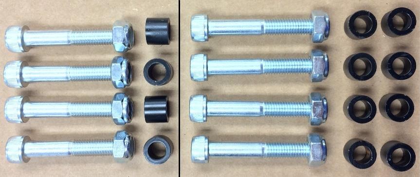
1 Installation Instructions: Alpha Doors CFMOTO ZForce 500 / 800 / 800EX *** SAFETY FIRST: ALWAYS DISCONNECT THE NEGATIVE BATTERY LEAD ON YOUR MACHINE PRIOR TO PERFORMING ANY MAINTENANCE OR INSTALLATION. THE BATTERY IS LOCATED IN THE REAR OF THE MACHINE, AT THE FRONT OF THE FENDER WELL OF THE LEFT REAR TIRE. *** Step 1: Temporarily disconnect factory door nets leaving front lower bolt attached. Step 2: Remove the factory driver seat by reaching through the seat and lifting up on the quick-release latch underneath the back of the seat. Step 3: Start by removing the three (3) factory bolts underneath the side panel (see photo below). Step 4: Remove factory nylon push rivets. This includes (see photos): Four (4) rivets on top of the side panel (see photo below - left) Six (6) rivets on the forward most part of the fender flare (see below - right) (Step 4 continued on next page)
 rivets on the")

 rivets under rear")


2 Step 4: (continued) Four (4) rivets on the forward section of the rear fender (see photo below top left) Three (3) rivets under rear fender flare on passenger side only (see photos below top right, bottom left and bottom right) Step 5: Remove rear factory side panel bolt (see photos below).
.")
 and lower (see photo below - right) factory attachment bolts for the")


. Remove the lower tube.")
3 Step 6: Remove two (2) upper and two (2) lower factory bolts holding the upper tube in place. Remove the upper tube (see photo below). Step 7: Reaching in behind the plastic, remove the upper (see photo below - left) and lower (see photo below - right) factory attachment bolts for the lower tube. Lower bolt will be used in Step 10. When installing the passenger side, it is necessary to remove the gas cap to pull back fender flare where lower bolts are located under plastic. Pull fender flare out and replace gas cap during next steps. Step 8: Remove factory bolt that attaches through the plastic to the lower tube (see photo below - left). Remove the lower tube. Step 9: Remove the factory floor pan bolt (see photo below - right). Floor pan bolt will be used in step 10.
.")


.")
4 Step 10: Slide Large Bracket (see photo below left) into place and install using original hardware (lower attachment bolt of lower tube from Step 7 and floor pan bolt from Step 9). Tighten bolts completely (see photo below - right). Step 11: Remove gas cap and return fender flare to original position. Replace gas cap. Step 12: Reinstall three (3) factory side panel bolts from Step 3 and the factory rear side panel bolt from Step 5. Step 13: Reinstall all factory nylon push rivets on the side panel, fender flare and rear fender from Step 4. Step 14: Remove two (2) factory front roll bar bolts, being sure to hold mirror so it does not fall (see photo below - left). Step 15: Remove two (2) factory rear roll bar bolts (see photo below - right). Step 16: Remove factory bracket from mirror. Install the supplied Mirror Brackets (see photo below left) using factory bolts and supplied M6 Nylock Nuts (see photo below right). Set aside.


 M6")


 M6 Nuts and")
.")

 M5 Bolts")

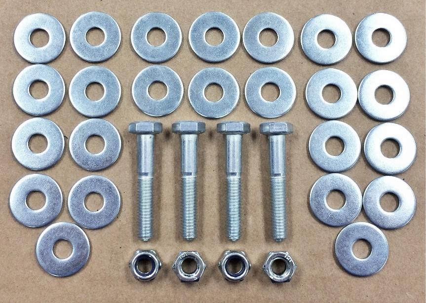
5 Step 17: Install the slam latch mechanism on to the door bracket using two (2) M6 x 35mm Bolts, four (4) M6 Small Washers (one under bolt head and one above nut so washers are on each side of bolt hole), two (2) M6 Nuts and snug tight (see photos below). Step 22: Install the release handle on the slam latch mechanism using two (2) M5 Bolts and two (2) M5 Nuts (see photo to left and below).
 between the center door frame mount and large bracket")


. Tighten but do not snug.")
 Small Black Spacers between the rear roll bar and door")
 M10 x 65mm Bolts through the door bracket, spacers and roll bar")
6 Step 18: Place door/frame on machine and insert four (4) M6 Large Washers (2 washers placed side by side) between the center door frame mount and large bracket (see photo below left). It may be necessary to add or decrease the number of washers to adjust height on frame. See Adjustment Guide for proper spacing and troubleshooting. Step 19: Place the supplied Bumper Assembly on the center door frame mount, inserting two (2) ¼ Washers and two (2) M6 x 35mm Bolts through the bumper assembly, center door frame mount and large bracket. Place one (1) ¼ washers and one (1) M6 Nuts to the underside of each bolt (see photo below right). Tighten but do not snug. See Adjustment Guide for proper spacing and troubleshooting. Step 20: Insert two (2) Small Black Spacers between the rear roll bar and door frame bracket (see photo below - top left). Insert two (2) M10 x 65mm Bolts through the door bracket, spacers and roll bar (see photo below middle). Apply two (2) Small Black Spacers to the end of each bolt then attach two (2) M10 Nuts (see photo below - bottom). Tighten but do not snug. See Adjustment Guide for proper spacing and troubleshooting.
 M10 x 60mm Bolts through the mirror mount, front door mount, and roll bar (see photos below - top).")


7 Step 21: Take driver side mirror with the installed replacement mirror bracket and place bracket above the front door frame bracket and against the roll bar. Insert two (2) M10 x 60mm Bolts through the mirror mount, front door mount, and roll bar (see photos below - top). Apply two (2) Small Black Spacers on the interior side of the bolts and install two (2) M10 Nuts (see photos below - bottom). Tighten but do not snug. See Adjustment Guide for proper spacing and troubleshooting. Step 22: Snug bolts and nuts on front and rear roll bar mount and center mount. See adjustment guide for proper spacing and troubleshooting. Step 23: Install striker pin by removing bottom 5/16 Flange Nut DO NOT remove top nut from pin. Insert the threaded end of the Striker Pin through the center of the mount. Reattach 5/16 Flange Nut, tighten but do not snug. Step 24: Close door and latch. The striker pin should sit directly in the center of the loading mechanism after the second click. See Adjustment Guide for proper spacing and troubleshooting. Step 25: It may be necessary to adjust the door bumper at this time. See adjustment guide for proper spacing and troubleshooting. Step 26: Reinstall seats and reconnect battery. Step 27: Reconnect door nets. The center strap of the door net will now wrap around the center door frame bracket (see photo). The remaining net will be reattached to its factory setup.

.")
.")
8 Adjustment Guide: Alpha Doors CFMOTO ZForce 500 / 800 / 800EX ***PROPER ADJUSTMENT OF YOUR DOORS IS CRITICAL TO KEEP YOU AND YOUR RIDERS AS SAFE AS POSSIBE AND GET THE LONGEST LIFE OUT OF YOUR ALPHA DOORS. THIS GUIDE WILL AID YOU DURING INSTALLATION, AS WELL AS BEFORE AND AFTER USE ADJUSTMENTS TO GET THE BEST AND PROPER FIT POSSIBLE. ASSISTANCE MAY BE REQUIRED DURING ADJUSTMENT. *** Gap Adjustment: 8mm Gap (approx. 5/16 ) The gap between the front frame and door should measure no less than 8mm (approx. 5/16 ) after installed. If gap is less than 8mm, adjustments will need to be made so that door will NOT hit frame during use (see photo left). To adjust height of gap properly, push the front roll bar bracket forward and snug bolts and nuts completely (see photo below left). Then, repeat this step with the rear roll bar bracket to flex door frame and increase gap (see photo below right). Once proper height is achieved, it may be necessary to add or remove washers between center door frame mount and large bracket in step 18 of installation instructions. Additional washers have been provided for use in adjustment. Striker Pin Adjustment: After adjustment of gap, it may be necessary to adjust the striker pin so that it latches properly. The correct placement of the striker pin should set directly in the center with the loading mechanism on the second click. See photos on next page showing proper adjustment of striker pin.


9 Proper adjustment of striker pin Striker pin adjusted too low Striker pin adjusted too high Bumper Adjustment: After adjustment of gap and striker pin, it may be necessary to adjust the placement of the door bumper. When properly adjusted, the door should latch on the first click with no pressure. Slight pressure will be necessary when securing door latch on the second click. If door will not preload on first click, increase washers by one and test. Add washers until door latches easily on first click. If much pressure is required to preload door on first click, reduce washer by one and test. Remove washers until door latches easily on first click. Tips: After installation of doors, ride your machine through rough terrain then check fitment again. It may be necessary to make adjustments again. Always check fitment before and after each ride to see if adjustments need to be made and to get the longest life out of your doors. Over time and use, the body of your UTV may flex and alter. This may also require adjustments to be made.
:")


10 Contents (cont d): Alpha Doors CFMOTO ZForce 500 / 800 / 800EX
WOC Mid Size Door Installation
 WOC-10112 Mid Size Door Installation NOTE: If the Mid Size Ranger that you are installing this door system on is a 2010 or newer you will need to remove the sill plates and side nets. If the doors are
Wildcat System Instructions
 Wildcat System Instructions NOTE: Most steps contained in these instructions will need to be repeated on the other side of the vehicle. Prior to assembly of windshield it is necessary to establish what
Prepare to Install Rock Doors
 2. Verify all parts have been received in this kit by checking the parts list at the end of this document. JEEP WRANGLER, RUBICON, UNLIMITED ROCK DOOR KIT INSTALLATION INSTRUCTIONS 1980-1986 CJ 1987-1995
PRP Seats 570/800/900 RZR 4 Doors
 Install Instructions PRP Seats 570/800/900 RZR 4 Doors Remove all parts from the box and unwrap completely using the packaging to lay out the pieces. Tools Needed: (not included) 7/16 Open end wrench and
Rear bumper cannot be used for towing after installation of the rear bumper relocation brackets.
 921RC7030 GM 88-98 4WD 1500 P/U 3 Body Lift Thank you for choosing Rough Country for all your suspension needs. *RC703BAG2* RC703BAG2 Rough Country recommends a certified technician install this kit. Attempts
INSTALLATION & OWNER S MANUAL
 Page 1 of 16 INSTALLATION & OWNER S MANUAL YAMAHA VIKING CAB KIT WITH HARD DOORS p/n: 1YAMVK fits model years 2014- (fits Yanmar Bull model years 2017-) NOTE: By design, the doors are made to not be removable!
(Ford Transit Rear Bumper) INSTALLATION INSTRUCTIONS
 INSTALLATION INSTRUCTIONS") Aluminess Products Inc 9402 Wheatlands Ct. #A Santee, CA 92071 619-449-9930 (Ford Transit Rear Bumper) INSTALLATION INSTRUCTIONS Please read before beginning Stainless steel hardware may bind together
Aluminess Products Inc 9402 Wheatlands Ct. #A Santee, CA 92071 619-449-9930 (Ford Transit Rear Bumper) INSTALLATION INSTRUCTIONS Please read before beginning Stainless steel hardware may bind together
ProPass-200 Top Dresser
 Setup Manual Form No. 3365-184 Rev A ProPass-200 Top Dresser Model No. 44700-Serial No. 310000001 and Up Model No. 44701-Serial No. 310000001 and Up Model No. 44704 Model No. 44705 Model No. 44706 Model
HiBoy Maverick/Commander Doors Part # HiBoy4 Maverick/Commander Doors Black
 Racing 3191 N Washington St. Suite 2 Chandler, AZ 85225 1 (800) 708-9803 http://www.racing.com HiBoy Maverick/Commander Doors Part # 07-2001 HiBoy4 Maverick/Commander Doors Black Congratulations on your
Assembly Instructions
 Assembly Instructions Part Number Description Model Approx. Assembly Time 99994-0903 Windshield Wiper Kit Mule SX 1 Hour WARNING Improper installation of this accessory could result in an accident causing
P3066 INSTALLATION MANUAL
 P3066 INSTALLATION MANUAL Parts List 1 Grille guard 1 Driver / left frame bracket Level of Difficulty Moderate Scan for helpful install tips 1 Passenger / right frame bracket 1 Driver / left top bracket
RT1 DUAL OUTLET SLIP-ON EXHAUST HONDA CBR600RR Rev B
 18-1022-723-02 08 50 44541 Rev B PARTS INCLUDED Ref. Part Number Description Qty 1) 00-200-00042 Slip-on S-bend Assembly 1 2) 00-200-01197 Stainless Steel Dual Outlet Muffler 1 3) 03-46-42766 Muffler Mounting
INSTALLATION INSTRUCTIONS ELEVATION REAR BUMPER FORD SUPERDUTY F #PW016687
 INSTALLATION INSTRUCTIONS #PW016687 PARTS LIST: 1 Elevation Bumper Assembly 2 Plastic Plugs for license plate mount 2 2-hole Spacer Plates (for tow hitch only) 8 4mm x 10mm Socket Head Screws 4 Sensor
Installation Instructions
 Installation Instructions TrailView Soft Top Important Safety Information For proper installation and best possible fit, please read all instructions BEFORE you begin. Periodically check all components
JK REAR BUMPER AND TIRE CARRIER
 JK REAR BUMPER AND TIRE CARRIER Installation Guide AEV30105AA (Updated 5/10/10) Page 1 of 20 Page 2 of 20 EXPLODED VIEW PLEASE READ BEFORE YOU START IN ORDER TO INSTALL THIS PART PROPERLY YOU OR YOUR INSTALLER
Passenger/Right. Driver/Left. Driver/Left Side Frame. Mounting Bracket. (2) 12mm Double Nut Plates (models without tow hooks)
 12mm Double Nut Plates (models without tow hooks)") PARTS LIST: Qty Description Qty Description 1 Grille Guard 4 10-1.5mm x 30mm Hex Bolt 1 Driver/left Frame Bracket 8 10mm x 24mm OD x 2.2mm Flat Washer 1 Passenger/right Frame Bracket 4 10-1.5mm Nylon Lock
PARTS LIST: Qty Description Qty Description 1 Grille Guard 4 10-1.5mm x 30mm Hex Bolt 1 Driver/left Frame Bracket 8 10mm x 24mm OD x 2.2mm Flat Washer 1 Passenger/right Frame Bracket 4 10-1.5mm Nylon Lock
2015 Ford F150 Rear Bumper w/ LED
 2015 Ford F150 Bumper w/ LED T527990 T527991 PARTS LIST: 1 Bumper Assembly 4 12mm Lock Washers 2 Mounting Brackets 6 12 mm Nylon Lock Nuts 4 Sensor Hole Plugs 8 4mm x 10mm Button Head Bolts 2 Plastic Plugs
Installation Instructions I - Sheet Number I-TVR-01 Rev. A
 Installation Instructions I - Sheet Number I-TVR-01 Rev. A TrailView Soft Top For proper installation and best possible fit, please read all instructions BEFORE you begin. For technical assistance or to
INSTALLATION MANUAL. Level of Difficulty. Parts List. Product Image. Tools Required. Notes and Maintenance. Torque Specifications.
 INSTALLATION MANUAL Parts List 1 Bull bar 2 Upper frame mounting bracket 1 Driver / left lower frame mounting bracket 1 Passenger / right lower frame mounting bracket 2 Button head bolt, 6mm 4 Flat washer,
INSTALLATION INSTRUCTIONS ELEVATION REAR BUMPER FORD F150
 INSTALLATION INSTRUCTIONS PARTS LIST: 1 Elevation Bumper Assembly 2 Plastic Plugs (license plate mount) 6 12-1.75mm x 50mm Hex Bolts 8 4mm x 10mm Socket Head Screws 12 12mm x 37mm OD x 3mm Flat Washers
INSTALLATION INSTRUCTIONS CHEVY C-10 4-Link Rear End
 INSTALLATION INSTRUCTIONS 73-87 CHEVY C-10 4-Link Rear End Please read these instructions completely before starting your installation. Assemble suspension on vehicle before powder-coating to ensure proper
97-02 JEEP TJ BODY LIFT KIT INSTRUCTIONS
 92RC60500 97-02 JEEP TJ BODY LIFT KIT INSTRUCTIONS Congratulations on your purchase of a new Rough Country 2 /3 Body Lift. We are committed to providing you with the best product available for the best
2. With the rear door open remove pull-style clip from the passenger side just below the door latch.
 LoD Offroad FJ Cruiser Rear Bumper with Tire Carrier Installation Instructions 1. Begin with removing factory spare from the rear door. 2. With the rear door open remove pull-style clip from the passenger
INSTALLATION INSTRUCTIONS GRILLE GUARD F-150 P/N 3066;3066-2
 INSTALLATION INSTRUCTIONS P/N 3066;3066-2 PARTS LIST: 1 Grille Guard 4 12mm Lock Washer 1 Driver/left Frame Bracket 4 10-1.5mm x 30mm Hex Bolt 1 Passenger/right Frame Bracket 8 10mm x 24mm OD x 2.2mm Flat
INSTALLATION GUIDE. JK Rear bumper & tire carrier. AEV30105AC Last Updated: 10/11/16 US PATENT: D642,502 ; D
 AEV30105AC Last Updated: 10/11/16 JK Rear bumper & tire carrier US PATENT: D642,502 ; D633.024 INSTALLATION GUIDE PLEASE READ BEFORE YOU START TO GUARANTEE A QUALITY INSTALLATION, WE RECOMMEND READING
09-12 Dodge 4WD Leveling Kit
 9235900 09-12 Dodge 4WD 1500 2.5 Leveling Kit Thank you for choosing Rough Country for all your suspension needs. DOES NOT FIT TRX PACKAGE VEHICLES!! Rough Country recommends a certified technician install
Ford Super Duty Recoil Traction Bar System. Part#: ,123409
 Part#: 123418,123409 Ford Super Duty Recoil Traction Bar System Rev. 011017 491 W. Garfield Ave., Coldwater, MI 49036. Phone: 517-279-2135 Web/live chat: www.bds-suspension.com. E-mail: tech-bds@sporttruckusainc.com
INSTALLATION GUIDE Front Bumper. KL Cherokee (Trailhawk)
") INSTALLATION GUIDE Front Bumper KL Cherokee (Trailhawk) Included Hardware: Sample Sample Sample Skill Level: 5/5 stars (Professional install recommended) Disclaimer Expedition One is not responsible for
INSTALLATION GUIDE Front Bumper KL Cherokee (Trailhawk) Included Hardware: Sample Sample Sample Skill Level: 5/5 stars (Professional install recommended) Disclaimer Expedition One is not responsible for
INSTALLATION MANUAL
 INSTALLATION MANUAL 1500350 Parts List 1 Driver / left inner fender liner 1 Passenger / right inner fender liner 4 Z-hanger brackets 1 Thread-set bolt, M6 1 Thread-set washer 1 Thread-set spacer 22 Hex
INSTALLATION INSTRUCTIONS Chevrolet Nova Superide II Independent Front Suspension
 INSTALLATION INSTRUCTIONS 1962 1967 Chevrolet Nova Superide II Independent Front Suspension Please read these instructions completely before starting your installation. Assemble suspension on vehicle before
MAZDASPEED3 Intercooler Instructions
 MAZDASPEED3 Intercooler Instructions Congratulations on your purchase of the COBB Tuning Front Mount Intercooler System for your 2007-2009 Mazdaspeed3. The following instructions should assist you through
Factory Five Racing, Inc. 818 Kit Assembly manual revision 1J update
 Factory Five Racing, Inc. 818 Kit Assembly manual revision 1J update Turbo coolant overflow tank...1 Shifter handle...4 Install...4 Door skin...7 Door Liner... 10 Side mirrors... 14 Door handles and pulls...
INSTALLATION INSTRUCTIONS ELEVATION FRONT BUMPER DODGE RAM
 INSTALLATION INSTRUCTIONS PARTS LIST: 1 Elevation Bumper Assembly 24 12mm x 37mm OD x 3mm Flat Washers 2 Frame Mounting Brackets 12 12mm Nylon Lock Nuts 8 12-1.75mm x 50mm Hex Bolts 2 License Plate Mounting
Left and Right Bar Light L Brackets. Driver/Left Frame Bracket
 PARTS LIST: 1 Bumper 14 12mm Nylon Lock Nuts 1 Bull Nose Hoop 2 10mm Double Bolt Plates 1 Winch Tray 4 10-1.5mm x 25mm Hex Bolts 1 Driver/left Frame Mounting Bracket 8 10mm x 30mm x 2.5mm Flat Washers
General Front Windshield
 General Front Windshield **WATCH OUR INSTALL VIDEO ALONG WITH INSTALL SHEET. 8-5/16-18x1 Black Carriage Bolts 8-5/16 Black Nylock Nuts 2-5/16x1-1/4 Stainless Steel Socket Head Screws 2-Rubber Grommets
INSTALLATION & OWNER S MANUAL
 Pg. 1 of 14 INSTALLATION & OWNER S MANUAL John Deere Gator XUV 825i S4 Cab (p/n: 1GTRXUV4 Steel Cab with Doors) The contents of this envelope are the property of the owner. Be sure to leave with the owner
BJ74SY FITTING INSTRUCTIONS
 BJ74SY FITTING INSTRUCTIONS REPLACES: 00.00.00 REVISED: 05.08.13. Check installation hardware before commencing. 1. Lift bonnet. JEEP GRAND CHEROKEE OVERLAND WK MY14 6/13on BIG TUBE PROTECTION BAR WITH
»Product» Safety Warning
 C1351 Installation Instructions 2014 Chevy/GMC, ½ Ton, 2/4wd 3.5" Combo Kit Read and understand all instructions and warnings prior to installation of product and operation of vehicle. Zone Offroad Products
Rear Bumper Cover Unpainted ( ):
:") Rear Bumper Cover Unpainted (1999-2004): Tools Required: Ratchet Socket extension 7/16 deep well socket 7/16 wrench 5/16 socket Fastener Removal Tool Offset Phillips screwdriver Extendable magnet (optional
Rear Bumper Cover Unpainted (1999-2004): Tools Required: Ratchet Socket extension 7/16 deep well socket 7/16 wrench 5/16 socket Fastener Removal Tool Offset Phillips screwdriver Extendable magnet (optional
Set Up instructions DB30 Doodlebug Removal from crate
 Set Up instructions DB30 Doodlebug Removal from crate 1. Remove carton top 2. Remove set up instuctions, owners manual and parts. E - REV - B Hardware and Parts Front fork assembly Hardware 10mm Front
6th generation (2015+) Mustang Harness Mount Bar Installation Instructions
 Mustang Harness Mount Bar Installation Instructions") R-1180 6th generation (2015+) Mustang Harness Mount Bar Installation Instructions A. Install harness bar 1. Remove front seats. First remove the plastic bolt covers front and rear using a small flat head
R-1180 6th generation (2015+) Mustang Harness Mount Bar Installation Instructions A. Install harness bar 1. Remove front seats. First remove the plastic bolt covers front and rear using a small flat head
FORD F-250/350 SUPER DUTY 4 WHEEL DRIVE FORD EXCURSION 4 WHEEL DRIVE FTS & 8 LIFT BOX KIT
 2000-2004 FORD F-250/350 SUPER DUTY 4 WHEEL DRIVE 2000-2005 FORD EXCURSION 4 WHEEL DRIVE FTS421-1 5.5 & 8 LIFT BOX KIT FTS421-1 BOX KIT FT30331 Hdwr Sub-Assembly Kit Qty Part # Description Qty Part # Description
Installation Instructions BR20 Rear Bumper Replacement Part # 28178T Toyo ta Tundra 2/4WD
 Installation Instructions BR20 Rear Bumper Replacement Part # 28178T 2014-2016 Toyo ta Tundra 2/4WD Excludes Models with B lind Spot Monitoring & Cross Traffic Alert Parts List Item Qty. Part # Description
K9-F17 INSTALLATION INSTRUCTIONS K9 Kit for FORD INTERCEPTOR SEDAN
 K9-F17 INSTALLATION INSTRUCTIONS K9 Kit for 2013-2018 FORD INTERCEPTOR SEDAN TOOLS Needed: Phillips Screw Driver Trim panel removal tools Caulk Gun Standard Socket set Metric Socket set Wire Cutters /Crimpers
Commander SUSPENSION SYSTEM INSTALLATION INSTRUCTIONS
 PARTS INCLUDED: 2 - FRONT UPPER A-ARMS 2 - FRONT LOWER A-ARMS 4 - COTTER PINS 2-12MM JAM NUTS 2 - TIE ROD EXTENDERS 8- FLANGED DELRON BUSHINGS 4- DELRON CASTER SPACERS 6 - GREASE FITTINGS 3 - BEARING REMOVAL
INSTALLATION INSTRUCTIONS HEAVY DUTY FRONT BUMPER 2015 FORD F150
 INSTALLATION INSTRUCTIONS PARTS LIST: 1 Heavy Duty Bumper Assembly 14 12-1.75mm x 45mm Hex Bolts 1 Driver/Left Frame Mounting Bracket 28 12mm x 37mm x 3mm Flat Washers 1 Passenger/Right Frame Mounting
INSTALLATION INSTRUCTIONS ELEVATION FRONT BUMPER 2018 FORD F150
 INSTALLATION INSTRUCTIONS PARTS LIST: 1 Elevation Bumper Assembly 28 12mm x 37mm x 3mm Flat Washers 1 Driver/Left Frame Mounting Bracket 4 12mm Lock Washers 1 Passenger/Right Frame Mounting Bracket 12
INSTALLATION INSTRUCTIONS HEAVY DUTY FRONT BUMPER CHEVY SILVERADO 1500
 INSTALLATION INSTRUCTIONS PARTS LIST: 1 Heavy Duty Bumper Assembly 16 12mm Nylon Lock Nuts 1 Driver Mounting Bracket 8 4mm x 10mm Socket Head Screws 1 Passenger Mounting Bracket 4 Sensor Plugs 4 Support
INSTALLATION INSTRUCTIONS FORD F-150 2WD & 4WD RETAINS FACTORY TOW HOOKS PART #P3063
 INSTALLATION INSTRUCTIONS FORD F-150 2WD & 4WD RETAINS FACTORY TOW HOOKS PART #P3063 PARTS LIST: 1 Grille Guard 2 10-1.5mm Nylon Lock Nuts 1 Driver/Left Frame Mounting Bracket 4 12mm Plastic Washers 1
1 M-3000-H4 F150 4X4 Lowering Kit
 READ INSTRUCTIONS COMPLETELY THROUGH BEFORE STARTING. IT IS RECOMMENDED THAT INSTALLATION BE DONE BY A QUALIFIED MECHANIC. REPLACE ALL STOCK PARTS THAT ARE DAMAGED OR WORN. ALWAYS WEAR EYE PROTECTION.
EVO Manufacturing. EVO-3032/3032B JL JLU HD Hinge Tire Carrier
 EVO Manufacturing EVO-3032/3032B JL JLU HD Hinge Tire Carrier READ BEFORE INSTALLATION: Some backspacing wheels/tire width combinations (small backspacing/wide tires) may require a single wheel spacer
Installation Instructions
 Equipment Required: Fastener Kit: F Wrenches: ¾, 7/8, 15/16 Drill Bits: 1/8, 9/16, 5/8 1-1/8 HOLE SAW Other Tools: Center Punch, Measuring Tape Installation Instructions 5 WARNING: Under no circumstances
INSTALLATION & OWNER S MANUAL
 p. 1 of 15 INSTALLATION & OWNER S MANUAL Polaris Ranger 500-800 PathPro SS Cab (fits 2010 - current) (p/n: 1POLRFS1) The contents of this envelope are the property of the owner. Be sure to leave with the
INSTALLATION INSTRUCTIONS
 INSTALLATION INSTRUCTIONS Accessory HARD FRONT DOORS P/N 0SU95-HL3-104A Application After 16 SXS700M2/M2D/M4/M4D Honda Dealer: Please give a copy of these instructions to your customer. Publication No.
JEEP TJ/LJ REAR BUMPER INSTALLATION INSTRUCTIONS
 JEEP TJ/LJ REAR BUMPER INSTALLATION INSTRUCTIONS JRR4002-P JRR4102-P JRR-TL INCLUDED PARTS LIST- JRR-TL 2-12MM X 45MM BOLT 2-1/2 FLAT WASHER 2-1/2 SAE FLAT WASHER 4-7/16 NYLOCK NUT 8-7/16 X 1.25 BOLT 12-7/16
INSTALLATION & OWNER S MANUAL
 Rev. B, p. 1 of 25 INSTALLATION & OWNER S MANUAL POLARIS RANGER RCS (for models XP or HD) (for model years 2009-) cab without doors kit (p/n 1POLRCWD) cab with doors kit (p/n 1POLRC) doors only kit (p/n
11333 INSTALLATION INSTRUCTIONS
 11333 INSTALLATION INSTRUCTIONS Safety glasses should be worn at all times while installing this product. YEARS: 2011-PRESENT MAKE: MINI COOPER MODEL: COUNTRYMAN STYLE: SEDAN WARNING: NEVER EXCEED YOUR
TOYOTA TUNDRA TVIP V5
 Preparation Part Number: 08586-OC890 Conflicts Do not install into vehicles with Factory Alarm Systems or without Immobilizer. Do not use Techstream Lite for Registration. Recommended Sequence of Application
INSTALLATION INSTRUCTIONS FORD F-150 2WD & 4WD RETAINS FACTORY TOW HOOKS PART #P3063
 INSTALLATION INSTRUCTIONS FORD F-150 2WD & 4WD RETAINS FACTORY TOW HOOKS PART #P3063 PARTS LIST: 1 Grille Guard 2 10-1.5mm Nylon Lock Nuts 1 Driver/Left Frame Mounting Bracket 4 12mm Plastic Washers 1
Master Your Terrain (307)
") Master Your Terrain (307) 775 9565 www.tntcustoms.com Y-Link Extreme Duty Long Arm Coil Conversion Jeep Cherokee Installation Instructions Congratulations for purchasing a TNT, INC. Extreme Duty Y-Link
Master Your Terrain (307) 775 9565 www.tntcustoms.com Y-Link Extreme Duty Long Arm Coil Conversion Jeep Cherokee Installation Instructions Congratulations for purchasing a TNT, INC. Extreme Duty Y-Link
PT# Must Have TC Standard Series LCA s & 1.25 Wheel Spacers Installed
 159 North Maple St. Unit J, CORONA CA 92880 P. 951-737-9682 F. 951-737-9006 WWW.CHAOSFAB.COM PT# 86612 Secondary Shock Hoop: Standard Series Stock Length Lowers: 2005-2018 Tacoma 2003-2018 4Runner 2003-2018
Fig A. Addictive Desert Designs. Preparation: Removal:
 Preparation: Disconnect the negative battery terminal. Park the vehicle on level ground and set the emergency brake. We recommend reading through the installation instructions in whole before performing
MachoMan Moped Assembly Instructions. If you have no mechanical experience, please have the unit professionally assembled.
 MachoMan Moped Assembly Instructions If you have no mechanical experience, please have the unit professionally assembled. Tools needed: #2 Phillips Screwdriver, 14mm Socket, 12mm Socket, 10mm Socket, 14mm
INSTALLATION & OWNER S MANUAL
 p. 1 of 15 INSTALLATION & OWNER S MANUAL John Deere Gator PathPro SS Cab (fits all HPX and XUV models with the O.P.S. system installed) (p/n: 1GTRXUV) (O.P.S. = Operator Protective Structure) The contents
DOOR KIT P/N , APPLICATION BEFORE YOU BEGIN KIT CONTENTS. Verify accessory fitment at Polaris.com.
 DOOR KIT P/N 2882561, 2882562 APPLICATION Verify accessory fitment at Polaris.com. BEFORE YOU BEGIN Read these instructions and check to be sure all parts and tools are accounted for. Please retain these
RH INSTALL INSTRUCTIONS 2008 MODEL
 RH-800-2 INSTALL INSTRUCTIONS 2008 MODEL 1 Tips for Installing Rhinogear Products The recommended sequence for installing our Rhinogear line of products on your Rhino. This sequence will help with ease
(2) 12mm x 40mm Short Low Profile Bolt Plates. (2) Spacer Washers. (4) 12mm Plastic Retainers. Passenger/Right Front.
 12mm x 40mm Short Low Profile Bolt Plates. (2) Spacer Washers. (4) 12mm Plastic Retainers. Passenger/Right Front.") PARTS LIST: 1 Driver/Left Running Board with 1 Rubber Backing (use on SX & Limited models) 4 12mm Plastic Retainer 1 Passenger/Right Running Board with 1 Rubber 4 12mm Lock Washer Backing (use on SX &
PARTS LIST: 1 Driver/Left Running Board with 1 Rubber Backing (use on SX & Limited models) 4 12mm Plastic Retainer 1 Passenger/Right Running Board with 1 Rubber 4 12mm Lock Washer Backing (use on SX &
ECO-SERIES REAR BUMPER FORD F150 PART # FD-2962
 15-16 FORD F150 PART # FD-2962 Body Armor 4x4 272 Corporate Terrace St. Corona, CA 92879 951-808-0750 Customer Service hours: M-TH: 7:30am to 4:30 PM Pacific Time Friday: 8 AM Noon Pacific Time PARTS LIST:
ALL MOUNT UNIVERSAL ATV PLOW MOUNT KIT P/N ASSEMBLY / OWNERS MANUAL. Application PLOW PUSH FRAME NO , or
 ALL MOUNT UNIVERSAL ATV PLOW MOUNT KIT P/N 15-0050 ASSEMBLY / OWNERS MANUAL Application PLOW PUSH FRAME NO. 15-0070, 33-0000 or 33-0070 Before you begin, please read these instructions and check to be
RC4WD Diablo Instruction Manual
 Version 1.1 RC4WD Diablo Instruction Manual Thank you for your purchase. Welcome to the RC4WD family. This kit is a combination of many specially engineered and manufactured parts. Enjoy your build. This
RBACK OFFR O O OPERATIONS MANUAL Z A A D R
 RAZORBACK OFFROAD OPERATIONS MANUAL LIMITATION OF LIABILITY Operations Manual Inventive Edge LLC total liability for any and all losses and damages arising out of any cause whatsoever shall in no event
Assembly Instructions
 Assembly Instructions Part Number Description Model Approx. Assembly Time 99994-049 Cab Enclosure MULE SX 3-4 Hours WARNING Improper installation of this accessory could result in an accident causing serious
Parts and tools needed for installation- Cleaning and Painting -
 Thank you for the purchase of our JK Front Trail Doors. We have made these from 6061-T6 aluminum and reinforced them with stiffeners at the top that double as a comfortable armrest and support for Rugged
13136 INSTALLATION INSTRUCTIONS
 INSTALLATION INSTRUCTIONS Safety glasses should be worn at all times while installing this product. YEARS: 09-PRESENT MAKE: AUDI/PORSCHE MODEL: Q/MACAN (EXCLUDING HYBRID) STYLE: SUV WARNING: NEVER EXCEED
Tusk Pannier Racks. Instructions and information KLR
 1 Tusk Pannier Racks Instructions and information KLR650 2008 + Congratulations on your purchase of the Tusk Pannier Racks. These racks are made to handle extreme adventure riding, but work great for the
Flip Extension Install Instructions
 Tools Required: Tape Measure, knife, Allen key set, Phillips screwdriver, a 1/2" wrench, and a 1/2" socket 1.0 Preparing TRUCKBOSS Deck. 1.1 Remove the plastic end caps from the rear of the TRUCKBOSS deck.
ST 93 RIPPER INSTALL KIT
 ST 93 RIPPER INSTALL KIT P/N 2883777;2883778;2883779 APPLICATION The Timbersled Ripper ST93 Install Kit is designed to fit all Timbersled ST90 and ST93 Ripper models. This includes; Timbersled Model No.
EAM109SY FITTING INSTRUCTIONS
 EAM109SY FITTING INSTRUCTIONS REPLACES: 17.12.12 REVISED: 28.04.16 NX PAJERO MY15 11/14- ARC BAR PROTECTION BAR With fog lights VEHICLE FRONTAL PROTECTION SYSTEM (VFPS) FOR AIR BAG & ADR COMPLIANT VEHICLES
INSTALLATION INSTRUCTIONS FORD SUPER DUTY NOTE: (Vehicle Retains Tow Hook) PART # P3064
 PART # P3064") INSTALLATION INSTRUCTIONS 2011-14 FORD SUPER DUTY 250-550 NOTE: (Vehicle Retains Tow Hook) PART # P3064 PARTS LIST: Qty Description Qty Description 1 Grill Guard 2 10mm x mm Hex Bolts 1 Driver/Left Lower
INSTALLATION INSTRUCTIONS 2011-14 FORD SUPER DUTY 250-550 NOTE: (Vehicle Retains Tow Hook) PART # P3064 PARTS LIST: Qty Description Qty Description 1 Grill Guard 2 10mm x mm Hex Bolts 1 Driver/Left Lower
09-12 Dodge 4WD /4 Body Lift
 92RC80000 09-12 Dodge 4WD 1500 1 1/4 Body Lift Thank you for choosing Rough Country for all your suspension needs. Rough Country recommends a certified technician install this kit. Attempts to install
4331 EUCALYPTUS AVE. ~~ CHINO, CA Fax FORD F-250/350 SUPER DUTY 4 WHEEL DRIVE
 4331 EUCALYPTUS AVE. ~~ CHINO, CA 91710 909-597-7800 Fax 909-597-7185 2001-2004 FORD F-250/350 SUPER DUTY 4 WHEEL DRIVE 2000-03 EXCURSION 4 WHEEL DRIVE FTS424-1BK 3.5 LIFT BOX KIT PARTS LIST: 1 EA. FRT.
C15C C15C. Page 1 of 20
 2 x Lid Front Hinge 1135 8 x M8 Bolt 8 x M8 Washer (3mm Thick) 4 x M6 Large washers 4 x M6 Spring washers 4 x M6 x 40mm Bolts 6 x M6 20mm Bolts 6 x M6 Washers 20 x Screws 2 x Lid mount gas strut bracket
Carli Suspension Front Instructions
 Carli Suspension Front Instructions 94-08 DODGE 2500-3500 4X4 SUSPENSION SYSTEM Note: Prior to installation, carefully inspect the vehicle=s steering and drive train components. Be sure to check ball joints,
Installation Instructions
 Installation Instructions CUSTOM QUICK INSTALL MOUNTING KIT 2011 & UP Ford Super Duty F-250/F-350/F-50 2011 & UP Part Number: 50073 WARNING: Under no circumstances do we recommend exceeding the towing
2010 to 2013 Toyota 4runner Rear bumper installation instructions:
 2010 to 2013 Toyota 4runner Rear bumper installation instructions: Note: This is one of the most difficult bumpers we product to install. The installation of this bumper requires cutting of the current
Comfort Ride Shock absorber system part numbers 2450, 2460 and 2470 Installation Instructions
 Comfort Ride Shock absorber system part numbers 2450, 2460 and 2470 Installation Instructions All specifications are subject to change without notice. MOUNTING FLANGE CENTER HOLE FRONT OF Item Qty Part
Jeep Wrangler (JK) Present
 Present") Suspension System RS66110B (3 SPORT SYSTEM w/ Progressive Coil Springs Front & Rear) 2012 NEWER JEEP MODELS EQUIPPED WITH 3.6L V6 ENGINE NEED EXHAUST MODIFICATION KIT RS720003. OR REPLACEMENT FRONT DRIVESHAFT
Suspension System RS66110B (3 SPORT SYSTEM w/ Progressive Coil Springs Front & Rear) 2012 NEWER JEEP MODELS EQUIPPED WITH 3.6L V6 ENGINE NEED EXHAUST MODIFICATION KIT RS720003. OR REPLACEMENT FRONT DRIVESHAFT
INSTALLATION INSTRUCTION BULL BAR DODGE RAM 1500 PART NUMBER
 INSTALLATION INSTRUCTION 09-12 DODGE RAM 1500 PART NUMBER - 200691 PARTS LIST: Qty Description Qty Description 1 Bull Bar 10 12mm Lock Washers 2 Upper Frame Mounting Brackets (for trucks without tow hooks
Installation Instructions KNOCK DOWN INSTATRUNK
 Installation Instructions KNOCK DOWN INSTATRUNK Vehicle Application: Jeep Wrangler and Wrangler Unlimited 2007 2010 : 42702 INSTALLATION TIME SKILL LEVEL 1/2 Hour 1 - Easy TOOLS 10 mm and 15 mm 9/16" and
Passenger/Right Top Support Bracket. (4) Spacer Plates (use on models without tow hooks. (2) 12mm x 100mm Double Bolt Plates
 Spacer Plates (use on models without tow hooks. (2) 12mm x 100mm Double Bolt Plates") GRILLE GUARD PARTS LIST: Qty Description Qty Description 1 Grille Guard 4 12-1.75mm Nylon Lock Nuts 1 Driver/left Frame Mounting Bracket 4 10-1.5mm x 30mm Hex Bolts 1 Passenger/right Frame Mounting Bracket
GRILLE GUARD PARTS LIST: Qty Description Qty Description 1 Grille Guard 4 12-1.75mm Nylon Lock Nuts 1 Driver/left Frame Mounting Bracket 4 10-1.5mm x 30mm Hex Bolts 1 Passenger/right Frame Mounting Bracket
INSTALLATION INSTRUCTIONS 3 BULL BAR W-BUILT IN LED LIGHT TOYOTA TACOMA
 INSTALLATION INSTRUCTIONS PARTS LIST: 1 3 Bull Bar 4 12mm Hex Nuts 1 Driver/Left Frame Mounting Bracket 2 10-1.50mm x 120mm x 30mm Hex Bolts 1 Passenger/Right Frame Mounting Bracket 2 10mm x 30mm OD x
4331 EUCALYPTUS AVE. ~~ CHINO, CA Fax FORD F-250/350 SUPER DUTY 4 WHEEL DRIVE FTS
 4331 EUCALYPTUS AVE. ~~ CHINO, CA 91710 909-597-7800 Fax 909-597-7185 2000-2003 FORD F-250/350 SUPER DUTY 4 WHEEL DRIVE FTS421-1 5.5 & 8 LIFT BOX KIT PARTS LIST: 1 EA. TRACK ARM BRKT. FT423-100 1 EA. PITMAN
03-04 Mach 1. Hellion Power Systems Mach 1 Kit Instructions
 Hellion Power Systems 03-04 Mach 1 Kit Instructions Part 1 Hellion recommends that the front suspension system be installed either by trained professionals or by 5.Remove rack bolts K-Member Installation
RUN/BRAKE/TURN AUXILIARY LIGHTS J
 RUN/BRAKE/TURN AUXILIARY LIGHTS J06236 2018-05-31 GENERAL Kit Numbers 67800589A, 69202276 Models For model fitment information, see the P&A retail catalog or the Parts and Accessories section of www.harleydavidson.com
»Product» Safety Warning
 D9151 Installation Instructions 2006-2008 Dodge Ram 1500 1.5" Body Lift Read and understand all instructions and warnings prior to installation of product and operation of vehicle. Zone Offroad Products
Sikky LSx BMW E30 Mount Kit Installation Guide
 Sikky LSx BMW E30 Mount Kit Installation Guide *This kit requires you to run aftermarket eyeball arms or control arm bushings and an E36 steering rack* 1- Remove stock motor, rad, and all attached hoses.
INSTALLATION OF FRONT MOUNTING KIT
 INSTALLATION OF FRONT MOUNTING KIT SAFETY PRECAUTIONS If any installation problems are encountered, please call G&B Specialties, Inc. for technical assistance before continuing with the installation process.!
LEXUS CT 200h ILLUMINATED DOOR SILLS Preparation
 Preparation Part Number: PT922-89100 Kit Contents Item # Quantity Req'd. Description 1 1 Door Sill, Front Right Hand 2 1 Door Sill, Front Left Hand 3 1 Door Sill, Rear Right Hand 4 1 Door Sill, Rear Left
SCION tc FOG LIGHT. Part Number: STC-312 / STC-812
 SCION tc 2011-2013 FOG LIGHT Part Number: STC-312 / STC-812 Kit Contents Item # Quantity Reqd. Description 1 2 Fog Lamps 2 2 Fog Light bezels 3 1 Switch Assembly 4 1 Fog Light Operation guide 5 1 Harness
w w w. h d o n l i n e s h o p. d e ELECTRA-GLO LIGHT BARS GENERAL INSTALLATION -J04723 REV Kit Number Models Kit Contents
 -J07 REV. 00-0-0 GENERAL Kit Number -09 Models For model fitment information, see the P&A Retail Catalog or the Parts and Accessories section of www.harley-davidson.com (English only). Kit Contents See