ADDRESSABLE DISCONNECT TOOL MODEL DE MANUAL
|
|
|
- Cornelia Sharp
- 5 years ago
- Views:
Transcription

1 Pg. 1 of 77 ADDRESSABLE DISCONNECT TOOL MODEL DE MANUAL REVISION HISTORY AUTHOR REVISED SECTION/PARAGRAPH REV RELEASED Gary Floyd Final Draft 0 03/31/17 Draft and Archived/Obsolete revisions are not to be used. Access Document Control System to verify revision.
2 Pg. 2 of 77 Table of Contents 1. PURPOSE SCOPE TOOL SPECIFICATIONS SAFETY ALWAYS NEVER REQUIRED TOOLS REQUIRED PARTS TOOL BLOCK DIAGRAM ASSEMBLY PROCEDURE INSPECTION ASSEMBLY PREPARATION FOR RUNNING IN THE WELL SERVICING PROCEDURES RECOMMENDATIONS REPLACEMENT OF THE DYNAENERGETICS DYNASELECT DETONATOR MAINTENANCE OF THE ADDRESSABLE DISCONNECT TOOL MODEL DE: ROUTINE REBUILDING THE ADDRESSABLE DISCONNECT TOOL MODEL DE: REBUILDING THE ADDRESSABLE DISCONNECT TOOL MODEL DE AFTER RELEASE OR WET RUN: REBUILDING THE ADDRESSABLE DISCONNECT TOOL MODEL DE QUICK CHANGE ADAPTER: REBUILDING THE ADDRESSABLE DISCONNECT TOOL MODEL DE CCL ADAPTER: REBUILDING THE ADDRESSABLE DISCONNECT TOOL MODEL DE FISHING NECK: OPERATIONAL PROCEDURES DISCONNECT PROCESS DYNAENERGETICS DYNASELECT PERFORATING OPERATIONS DYNAENERGETICS DYNASELECT RELEASING OPERATIONS APPLICABLE REFERENCES... 75
3 Pg. 3 of PURPOSE This manual describes the assembly, disassembly, service, maintenance, and operation of the ICSI Addressable Disconnect Tool Model DE. 2. SCOPE This manual provides an outline of the procedures used to assemble, disassemble, service, maintain, and operate the ICSI Addressable Disconnect Tool Model DE. This procedure, in conjunction with a Job Safety Analysis (JSA), provides the minimum standards for safe operations. Deviation from the procedure requires the approval of ICSI. Careful consideration of safety requirements and operational needs is an essential part of all job preparations and needs to include all field personnel present as well as Management. 3. TOOL SPECIFICATIONS 1. Tool is pull rated at 18,000 pounds in air. 2. Tool is rated for 22,000 psi. 3. Tool is rated for F. 4. SAFETY 1. Safety Glasses and steel toe boots are required during all operations. 2. Appropriate gloves are to be used as needed. 3. Always use the correct tools for the job being performed. 4. Replace broken or damaged tools immediately. 5. Meggers leave a powerful and dangerous residual charge. Always discharge by grounding the Megger and whatever was checked with the Megger before touching it. 6. Meggers are only to be used by properly trained personnel. 7. Federal Regulations will be the guidelines for any operations that involve handling explosives: a. Title 18, United States Code, Sec. 1102, Chapter 40. Importation, Manufacture, Distribution and Storage of Explosive Materials b. Title 27, Code of Federal Regulations, Part 555 Commerce in Explosives 8. The handling of explosives and explosive devices, or systems, will comply with State and Federal Regulations, API RP 67 Recommended Practice for Oilfield Explosives Safety, the Wireline Company s Explosives Safety Manual, and the
4 Pg. 4 of 77 Manufacturer s recommendations. Any deviation from the regulations, or the above listed guidelines, must be approved by the Wireline Company s Management. 9. Use caution when working on the tool and avoid pinch points. 10. Stay out of the line of fire for devices that are armed. 11. Do not Check Fire through the device if it has a Detonator installed. 12. Do not use a Megger when explosives or an electronic switch is in the tool. 5. ALWAYS 1. Inspect all parts for wear or damage. Repair or replace any worn or damaged parts. 2. Carefully inspect all threaded connections. 3. All parts must be clean, dry, and free of dust, dirt, metal shavings, and any other contaminants. 4. The Coupling Sleeve only needs to be hand tight. 5. O-rings always need to be greased with a high temperature grease. 6. Threads need to be coated with High Temperature Anti-Seize with the exception of the Slide Stud Adapter to Release Collar connection and the Release Collar to Actuator connection which get Loctite. 7. Be careful of damaging or pinching wires. 8. Check the wiring and subs for leakage and continuity before attaching explosive devices. 9. Tighten the CCL Adapter to the Actuator with 24 Pipe Wrenches. 10. Tighten the Fishing Neck to the Spline Nut with 24 Pipe Wrenches. Be extremely careful in placement of the pipe wrenches. The pipe wrench on the Fishing Neck can only be on the knurled portion of the Fishing Neck. Remove any pipe wrench marks from the Spline Nut with a file. 11. Tighten the Coupling Sleeve to the Actuator by hand. 12. Tighten the Quick Change Adapter to the Fishing Neck with 24 Pipe Wrenches. 13. Remove the Hydrostatic Equalizing Plug with a screw driver prior to unscrewing the Coupling Sleeve from the Actuator. 14. Use the Safety Tube and follow all Wireline Company Explosives Safety Procedures when arming the Addressable Disconnect Tool. 15. Replacement of the DynaEnergetics DynaSelect Detonator is dependent on well conditions and will be determined by the Wireline Company s Management. ICSI recommends that Detonators be replaced and scrapped or used on a gun after 6 runs.
5 Pg. 5 of 77 Problems with Detonator performance and thus with ADT performance have been observed when Detonators have been used for more than 6 runs. 16. Maintenance of the tool is recommended after 6 to 12 runs. This is a minimum recommendation for normal conditions and more frequent replacement of O-rings is acceptable. For high temperature, hostile environment operations maintenance is recommended after 4 to 6 runs. 17. Rebuilding of the tool is recommended after 40 runs or after the Tool has run wet or been released downhole. This is a minimum recommendation for normal conditions and more frequent rebuilding of the tool is acceptable. For high temperature, hostile environment operations rebuilding is recommended after 10 to 12 runs. 18. The Aluminum Gate must capture the rubber tip of the DynaEnergetics DynaSelect Detonator. If the Detonator is blocking the slot and will not allow the insertion of the Gate, the Detonator is not fully seated in the tool. 19. Note that the Addressable Disconnect Tool with the Detonator installed is an explosive device that should be handled with great care and treated per the Service Company Policies and Procedures in addition to Federal and State Laws and Regulations. 20. Set line tension to neutral weight at the tool prior to releasing the tool. 21. Always use a Blaster s Meter to check voltages when conducting check fire. 22. Wash the tool thoroughly after the job. Remember that corrosive wellbore fluids can remain in cracks, crevices, and connections and do a lot of damage especially when sitting over time. 23. Check all Quick Change Pins to ensure that they fully compress. If they do not fully compress, remove the cartridge from the Quick Change and adjust the allen screw in the bottom of the cartridge to allow the pin to fully compress. Failure to do this can cause the pin to crush the insulators in the Quick Change Adapter and can result in the Quick Change Pin being bent. This can lead to a misrun. 6. NEVER 1. Never Turn the Coupling Sleeve without first removing the Hydrostatic Equalizing Plug! Attempting to remove the Coupling Sleeve without first removing the Hydrostatic Equalizing Plug will shear the Hydrostatic Equalizing Plug and can result in the tool running wet! 2. Never tighten through the assembled Addressable Disconnect Tool! This will cause catastrophic failure! 3. Never tighten the Fishing Neck to the Actuator! This will cause catastrophic failure! Tighten the Fishing Neck while holding backup on the Spline Nut only. 4. Never check fire when explosives are loaded in the tool.
6 Pg. 6 of Never check fire by shorting the end of the tool with a screw driver. 6. Never modify the Addressable Disconnect Tool! 7. Never modify the DynaEnergetics DynaSelect Detonator in any way! 8. Never force the Detonator into the tool! The Detonator should slide down into the tool cleanly and should fully seat. 9. Never use the Teflon Gates as they are obsolete. The Teflon Gates do not properly restrain the Detonator and can result in a failure to release. 10. Never use a Megger to check the tool when either explosives are present in the tool or an electronic switch is present in the tool. 11. Never use excessive amounts of High Temperature Anti-Seize as it is conductive. If excess amounts are used on the threads it is possible for some of the Anti-Seize to seep down into the tool and cause a short in an electrical circuit. A light coating is sufficient. 7. REQUIRED TOOLS 1. Two 24 Pipe Wrenches 2. Flat Head Screwdriver 3. Wire Cutters 4. Wire Strippers 5. High Temperature Anti-Seize 6. Loctite 272 Red 7. Loctite 242 Blue 8. Allen Wrench Set 9. O-Ring Pick Set 10. Digital Multimeter 11. Megger 12. Vise 13. Washer Guide Tool 14. Digital Caliper 15. Hammer 16. File 17. Socket Set/Nut Drivers with two each deep sockets (1/4, 5/16, and 3/8 ) 18. 7/8 14 NF Tap for Threads at bottom of Actuator
7 Pg. 7 of Tap for Ground Screw Threads in Actuator 20. 1/4 28 Tap for HEP Threads in Coupling Sleeve and for Kemlon Connection Threads 8. REQUIRED PARTS 1. Model DE Addressable Disconnect Tool 2. Maintenance Kit a. 4x Duro Viton O-rings b. 2x Duro Viton O-rings c. 4x Duro Viton O-rings d. 5x Duro Viton O-rings e. 2x Brass Screws f. 2x SS 8-32 Screws g. 3x Electrical Red Splice Boots 3. Post Release Rebuild Kit a. 4x Duro Viton O-rings b. 2x Duro Viton O-rings c. 4x Duro Viton O-rings d. 2x Kemlon Boots (Large Boot) (Blue Wire) e. 2x Brass Screws f. 2x SS 8-32 Screws g. 1x Release Assembly i. 1x Slide Stud Adapter with Shear Ring ii. 1x 1 OD Releasing Collar with Retaining Ring h. 1x Aluminum Gate Insert i. 2x Hydrostatic Equalizing Plugs j. 3x Electrical Red Splice Boots k. 1x PEEK Kemlon Retainer 4. Recommended Stock of Spares for Routine Rebuilds a. 4x Duro Viton O-rings b. 2x Duro Viton O-rings

8 Pg. 8 of 77 c. 4x Duro Viton O-rings d. 2x Kemlon Boots (Large Boot) (Blue Wire) e. 2x Brass Screws f. 2x SS 8-32 Screws g. 2x Hydrostatic Equalizing Plugs h. 3x Electrical Red Splice Boots i. 1x PEEK Kemlon Retainer 9. TOOL BLOCK DIAGRAM CCL Adapter Actuator with Coupling Sleeve Fishing Neck CCL Adapter attaches to the bottom of the Shooting CCL. Actuator contains the DynaEnergetics DynaSelect Detonator, Release Collar, Shearing Collar, and Hydrostatic Equalizing Plug. 2 Fishing Neck is left in Well after Disconnecting the Tool. Quick Change Adapter Quick Change Adapter allows attachment of Quick Change to Fishing Neck. CCL Adapter Coupling Sleeve
9 Pg. 9 of 77 Actuator Fishing Neck Quick Change Adapter 10. ASSEMBLY PROCEDURE 10.1 Inspection 10.2 Assembly 1. Inspect all parts for wear or damage. Repair or replace any worn or damaged parts. 2. Carefully inspect all threaded connections. 3. All parts must be clean, dry, and free of dust, dirt, metal shavings, and any other contaminants. This is the recommended best practice for the assembly of this tool. This represents the Manufacturer s recommendation and results in the most efficient and effective assembly of the tool. Never tighten through the assembled Addressable Disconnect Tool! This will cause catastrophic failure! Never attempt to turn the Coupling Sleeve without first removing the Hydrostatic Equalizing Plug! This can damage the HEP and cause a misrun. Steps 1 through 6 are performed by ICSI Personnel at the Manufacturing Facility. The Releasing Collar Assembly is sold as a unit and not as individual pieces. Do Not disassemble the Releasing Collar Assembly! The information is provided here for reference purposes only. High Temperature Anti-Seize is conductive. If excess amounts are used on the threads it is possible for some of the Anti-Seize to seep down into the tool and cause a short in an electrical circuit. 1. Place the Shearing Collar on the Slide Stud Adapter. The bevel side of the Shearing Collar should be up towards the small diameter threads. Screw the long set screw into the Shearing Collar and through the Slide Stud Adapter. Tighten the set screw. 2. Insert the Washer Guide Tool in the Releasing Collar and place a washer on the end of the Guide Tool.


10 Pg. 10 of Put red Loctite 272 on the Slide Stud Adapter threads and screw it into the Releasing Collar. Tighten until a gap of to is left between the Releasing Collar and the Slide Stud Adapter due to the presence of the Nord Lock Washer. Check the gap with a digital caliper. It will be necessary to place the Releasing Collar in a vise to properly tighten it and achieve the necessary gap. Gap should be between and Place a snap ring around the Releasing Collar just below the groove.

11 Pg. 11 of Place a 208 O-ring on the Releasing Collar in the groove near the top of the Releasing Collar. 6. Place the Retainer Ring over the O-ring on the Releasing Collar and slide the snap ring up against the retainer ring. The Retainer Ring should extend slightly above the shoulder of the Releasing Collar. Retainer Ring Release Collar Shear Collar Slide Stud Releasing Collar Assembly 7. Place the Actuator in the vise. Orient the Actuator such that the Key is at 12 o clock and the top of the Actuator is secured tightly in the vise. 8. If the Key is in place, remove it by prying it out with a small screwdriver. 9. Put Blue Loctite 242 on the threads of the Releasing Collar Assembly and screw it into the bottom of the Actuator by hand until the flange on the bottom of the Slide Stud Adapter is close to the bottom of the Actuator.
12 Pg. 12 of Place the Spline Nut on the Slide Stud Adapter and slowly screw the assembly into the Actuator while keeping pressure on the Spline Nut. Stop when the Spline Nut is in contact with the Actuator. Note that the Slide Stud Releasing Collar Assembly will not be tight with the Actuator. This is normal.
13 Pg. 13 of 77 There should be no gap between the Spline Nut and the Actuator. 11. Remove the Spline Nut and put it back on trying to align the single slot with one of the two available keyways on the Actuator. Do not back off the assembly in this process. Turn only to the right.
14 Pg. 14 of Once the Spline Nut is aligned with a keyway, insert the key in the appropriate keyway. It will need to be tapped into place with a hammer. The Spline Nut can be removed for this process. Ensure that the Key is flush with the Actuator. If the Spline Nut was removed, replace it. The Spline Nut should be locked in and unable to turn. The Spline Nut must be against the Actuator.
15 Pg. 15 of Release the Actuator from the vise and rotate it 180 degrees such that the Key is on the underside of the Actuator. Tighten the vise. 14. Push the Shearing Collar up into the Actuator. Screw a Brass Shear Screw into the Actuator and snug it into place. This holds the Shearing Collar in place. Use only ICSI manufactured Brass Screws as their ends have been turned down to reduce the shear force required. 15. Coat the threads of the Slide Stud Adapter with High Temperature Anti-Seize. 16. Make up a large Kemlon Boot Connector with blue wire on the top of the Fishing Neck. The Boot is packed with grease. Push down and seat the Boot ensuring that there is no trapped air in the Boot.
16 Pg. 16 of Run the wire from the top of the fishing neck into the bottom of the Slide Stud Adapter. Fish the wire out of the Actuator Assembly below the Shearing Collar. 18. Thread the Fishing Neck onto The Slide Stud Adapter. Make up the Fishing Neck until hand tight against the Spline Nut which must be tight against the Actuator. Ensure that the Blue Wire from the Fishing neck does not get pinched. The Blue Wire may not turn with the tightening of the Fishing Neck as the Boot will catch in the Slide Stud Adapter. This is normal.
17 Pg. 17 of Use a 24 Pipe Wrench to hold backup on the Spline Nut. Place the other 24 Pipe Wrench on the Fishing Neck at the knurled area near the bottom of the Fishing Neck. Tighten the Fishing Neck onto the Actuator Assembly. After tightening, use a file to remove any tool marks from the Spline Nut. Tighten here Backup here 20. Measure and cut 1/8 OD Teflon Tubing that will extend from the Slide Stud Adapter through the hole in the Actuator housing. Then slide the tubing through the hole from above and feed the Blue Wire from the Fishing Neck through the tubing.
18 Pg. 18 of 77
19 Pg. 19 of 77 Older Actuators will not have hole through the Actuator, rather they will have a groove in the Actuator housing. Three Nylon Screws will be used to hold the tubing in the groove after the wire is run through the tubing and it is laid in the groove. Take a file to the three Nylon Screws to make them flush with the Actuator body. 21. Use a Digital Multimeter to check the CCL Adapter. Check for both continuity and leakage. A Megger can also be used to check for leakage since there are no explosives present. 22. Put 227 O-rings on the CCL Adapter Sub. Grease the O-rings and put High Temperature Anti-Seize on the threads of the CCL Adapter. High Temperature Anti-Seize is conductive. If excess amounts are used on the threads it is possible for some of the Anti-Seize to seep down into the tool and cause a short in an electrical circuit. 23. Make up a Large Boot with a Blue Through Wire on the Kemlon Connector on the bottom of the CCL Adapter. The Boot is packed with grease. Push down and seat the Boot ensuring that there is no trapped air in the Boot. Slide the PEEK Kemlon Retainer over the Blue Wire and down until it fits over the Boot and catches in the 113 O-ring in the CCL Adapter. 24. Feed the Blue Wire into the center hole at the top of the Actuator. Do Not Use offset hole for wire from CCL Adapter. Use Center Hole for wire from CCL Adapter. 25. Screw the CCL Adapter into the top of the Actuator while keeping light tension on the Blue Wire. Tighten the CCL Adapter to the Actuator with 24 Pipe Wrenches. 26. Use a Digital Multimeter to check the through connection from the bottom of the Fishing Neck to the inside of the Actuator. Check for both continuity and leakage.


20 Pg. 20 of 77 A Megger can also be used to check for leakage since there are no explosives present. Never use a Multimeter or a Megger to check an Addressable Disconnect Tool if either an electronic switch or explosives are in the tool! 27. Use a Digital Multimeter to check the connection from the end of the blue wire in the Actuator to the top of the CCL Adapter. Check for both continuity and leakage. A Megger can also be used to check for leakage since there are no explosives present. 28. Insert the aluminum Gate in the upper slot in the Actuator as shown. The long narrow slot goes down into the Actuator. The long narrow slot is wider on the downhole side of the Gate. The Gate will only go in one way as there is a large bulge on the down hole side of the Gate. The open side of the slot is designed to capture the rubber tip of the DynaEnergetics DynaSelect Detonator. Do not pinch any wires. The Blue Through Wire will lay in the notch at the top of the Gate. Do not use the older large slot Aluminum Gates or the Teflon Gates. They will not properly restrain the Detonator and can result in the Hydrostatic Equalizing Plug not shearing and the Release Collar not opening. 29. Coil up the excess wires and ensure that all the wires are tucked down in the Actuator. They must not be pinched by the Gate or near the surface of the Actuator where they could be pinched or damaged by the Coupling Sleeve. 30. Put 227 O-rings on the Actuator. 31. Put 226 O-rings on the inside of the Coupling Sleeve. Grease the O-rings. 32. Grease the O-rings and put High Temperature Anti-Seize on the threads of the Actuator. Put grease on the outside of the Fishing Neck where the internal O-rings on the Coupling Sleeve will sit. 33. Slide the Coupling Sleeve over the Fishing Neck and onto the Actuator. Screw the Coupling Sleeve onto the Actuator and make it hand tight. Do not overtighten!
21 Pg. 21 of Put a 008 O-ring on the Hydrostatic Equalizing Plug. Grease the O-ring and put High Temperature Anti-Seize on the threads of the Hydrostatic Equalizing Plug. Install the Hydrostatic Equalizing Plug in the Coupling Sleeve. Snug it down with a Screwdriver. Never Turn the Coupling Sleeve without first removing the Hydrostatic Equalizing Plug! Attempting to remove the Coupling Sleeve without first removing the Hydrostatic Equalizing Plug will shear the Hydrostatic Equalizing Plug and can result in the tool running wet! 35. Use a Digital Multimeter to check the Quick Change Adapter. Check for both continuity and leakage. A Megger can also be used to check for leakage since there are no explosives present.
22 Pg. 22 of Put 222 O-rings on the end of the Fishing Neck. Grease the O-rings and put High Temperature Anti-Seize on the threads of the Fishing Neck. Screw the Quick Change Adapter onto the bottom of the Fishing Neck. Tighten between the Quick Change Adapter and the Fishing Neck with two 24 Pipe Wrenches. High Temperature Anti-Seize is conductive. If excess amounts are used on the threads it is possible for some of the Anti-Seize to seep down into the tool and cause a short in an electrical circuit. 11. PREPARATION FOR RUNNING IN THE WELL This is the recommended best practice for this tool. This represents the Manufacturer s recommendation and results in the most efficient and effective assembly of the tool. Never tighten through the assembled Addressable Disconnect Tool! This will cause catastrophic failure! Never attempt to remove the Coupling Sleeve without first removing the Hydrostatic Equalizing Plug! This can damage the HEP and cause a misrun. The Releasing Collar Assembly is sold as a unit and not as individual pieces. Do Not disassemble the Releasing Collar Assembly! High Temperature Anti-Seize is conductive. If excess amounts are used on the threads it is possible for some of the Anti-Seize to seep down into the tool and cause a short in an electrical circuit. 1. Remove the Hydrostatic Equalizing Plug from the Coupling Sleeve.
23 Pg. 23 of Unscrew the Coupling Sleeve from the Actuator and slide it down. The Quick Change Adapter will stop it from coming off of the tool, but will leave enough room to prepare the tool for the job.
24 Pg. 24 of Use a Digital Multimeter to check the through connection from the bottom of the Quick Change Adapter to the Blue Wire inside of the Actuator. Check for both continuity and leakage. A Megger can also be used to check for leakage since there are no explosives present. Never use a Multimeter or a Megger to check an Addressable Disconnect Tool if either an electronic switch or explosives are in the tool! 4. Use a Digital Multimeter to check the connection from the end of the Blue Wire in the Actuator to the top of the CCL Adapter. Check for both continuity and leakage. A Megger can also be used to check for leakage since there are no explosives present. 5. Use a Digital Multimeter to check the Quick Change that will be run on the bottom of the Addressable Disconnect Tool. Check for both continuity and leakage. A Megger can also be used to check for leakage since there are no explosives present. Never use a Multimeter or a Megger to check an Addressable Disconnect Tool if either an electronic switch or explosives are in the tool! 6. Screw the Quick Change onto the Quick Change Adapter. 7. If the Addressable Disconnect Tool has not been attached to the CCL and the wireline, do so now. Tighten all connections from the CCL Adapter to the cablehead. 8. Remove the Gate from the Actuator. Pull out the Blue Wires. 9. Following all Service Company Explosive Safety policies, a DynaEnergetics DynaSelect Detonator can now be attached to the tool.
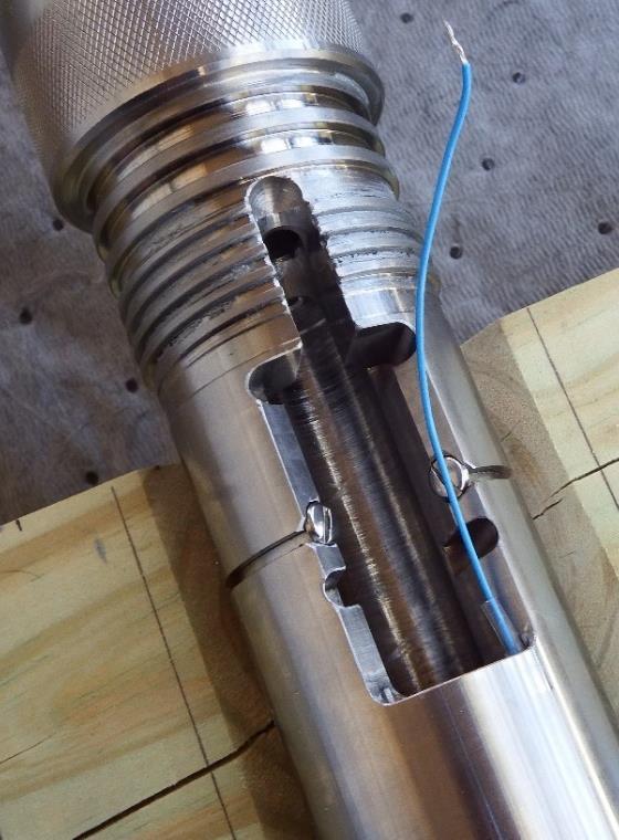
25 Pg. 25 of The DynaEnergetics DynaSelect Detonator should have a piece of 80 grain detonator cord inserted into the detonator. Cut the detonating cord off flush with the crimping sleeve of the detonator with a razor blade and wooden block. Dip the end of the crimping sleeve with the cut off piece of detonator cord into Plasti Dip to seal the end of the detonator cord. Alternatively, Elmer s Glue or RTV can be used to put a film on the end of the detonating cord to seal it and help hold it in the detonator s crimping sleeve. Do Not Crimp the Detonator to the small piece of detonating cord as this could deform the sleeve in such a way that it will not seat in the tool properly. 11. The DynaEnergetics DynaSelect Detonator should be in a Safety Tube with the wires accessible. 12. Attach the Red Detonator wire to the Blue Wire from the CCL Adapter. 13. The Black Ground Wire should be stripped and attached to one of the grounding lugs. Then wrap it around the Actuator keeping the wire in the groove and wrap it around the other grounding lug. Tighten the Lugs. 14. Attach the Blue Through wire from the Detonator to the Blue Wire from the Fishing Neck. 15. Remove the DynaEnergetics DynaSelect Detonator from the Safety Tube and insert it into the Actuator. It should slide all the way down into the Releasing Collar and bottom out. The aluminum Gate can be slid into the upper slot in the Actuator and the slot in the Gate will capture the rubber boot at the end of the DynaEnergetics DynaSelect Detonator. This prevents the Detonator from moving. Note that newer Gates have a wider slot on the side facing the Detonator. This prevents the Detonator from moving. Do not use the older large slot Aluminum Gates or the Teflon Gates. They will not properly restrain the Detonator and can result in the Hydrostatic Equalizing Plug not shearing and Release Collar not opening. 16. Tuck the wires back down into the Actuator. Ensure that the wires are tucked down such that they cannot be caught in the threads of the Coupling Sleeve. 17. Slide the Coupling Sleeve back up onto the Actuator and screw it onto the Actuator hand tight. 18. Inspect the 008 O-ring on the Hydrostatic Equalizing Plug and replace as necessary. Grease the O-ring and put High Temperature Anti-Seize on the threads of the Hydrostatic Equalizing Plug. Install the Hydrostatic Equalizing Plug in the Coupling Sleeve. Snug it down with a Screwdriver.
26 Pg. 26 of 77 Never Turn the Coupling Sleeve without first removing the Hydrostatic Equalizing Plug! Attempting to remove the Coupling Sleeve without first removing the Hydrostatic Equalizing Plug will shear the Hydrostatic Equalizing Plug and can result in the tool running wet! 19. The tool string is ready to go. Follow all Explosives Safety Protocols. 12. SERVICING PROCEDURES 12.1 Recommendations
27 Pg. 27 of 77 These are the recommended best service and maintenance practices for this tool. This represents the Manufacturer s recommendation and results in the most efficient and effective performance of the tool. These are the minimum recommended service intervals. More frequent servicing and rebuilding of tools is perfectly legitimate and up to the Wireline Company s Management. 1. The following are recommendations regarding maintenance of the Addressable Disconnect Tool during normal, routine operations: a) Replacement of the DynaEnergetics DynaSelect Detonator is dependent on well conditions and will be determined by the Wireline Company s Management. ICSI recommends that Detonators be replaced and scrapped or used on a gun after 6 runs. Problems with Detonator performance and thus with ADT performance have been observed when Detonators have been used for more than 6 runs. b) Maintenance of the tool is recommended after 6 to 12 runs. c) Routine Rebuilding of the tool is recommended after 40 runs. d) Rebuilding of the tool after a release or the tool running wet is required. 2. The following are recommendations regarding maintenance of the Addressable Disconnect Tool during high temperature, hostile environment operations: a) Replacement of the DynaEnergetics DynaSelect Detonator is dependent on well conditions and will be determined by the Wireline Company s Management. ICSI recommends that Detonators be replaced and scrapped or used on a gun after 6 runs. Problems with Detonator performance and thus with ADT performance have been observed when Detonators have been used for more than 6 runs. b) All switches degrade to some degree in high temperature environments as temperature effects are cumulative. The DynaEnergetics DynaSelect Detonator incorporates the switch in the detonator. Switches need to be checked carefully when operating in high temperature environments and more frequent replacement may be needed. c) Maintenance of the tool is recommended after 4 to 6 runs. d) Routine Rebuilding of the tool is recommended after 10 to 12 runs. e) Rebuilding of the tool after a release or the tool running wet is required.
28 Pg. 28 of Replacement of the DynaEnergetics DynaSelect Detonator This is the recommended best practice for this tool. This represents the Manufacturer s recommendation and results in the most efficient and effective assembly of the tool. Never tighten through the assembled Addressable Disconnect Tool! This will cause catastrophic failure! Never attempt to remove the Coupling Sleeve without first removing the Hydrostatic Equalizing Plug! This can damage the HEP and cause a misrun. High Temperature Anti-Seize is conductive. If excess amounts are used on the threads it is possible for some of the Anti-Seize to seep down into the tool and cause a short in an electrical circuit. 1. Following all Service Company Explosive Safety policies, a DynaEnergetics DynaSelect Detonator can be replaced. 2. Remove the Hydrostatic Equalizing Plug from the Coupling Sleeve. 3. Unscrew the Coupling Sleeve from the Actuator and slide it down. The Quick Change Adapter will stop it from coming off the tool, but will leave enough room to replace the Detonator.
29 Pg. 29 of Remove the Gate from the Actuator. 5. Pull the Detonator out of the Actuator and place it in the Safety Tube. 6. Disconnect the Blue Wire from the CCL Adapter to the Red Detonator Wire. Strip some insulation from the Red Detonator wire to allow shunting the detonator. 7. Disconnect the Black Ground Wire from the two Ground Lugs on the Actuator. 8. Shunt the Red Detonator Wire and the Black Ground Wire together. 9. Disconnect the Blue Through Wire from the Detonator and the Blue Wire from the Fishing Neck. 10. The Detonator can now be removed from the Safety Tube and prepared for transport back to the Service Company shop as per the Service Company s Explosive Operations Procedures and in accordance with Federal and State Regulations. 11. The new Detonator should be in a Safety Tube with the wires accessible. The detonator should be checked with a Blaster s Meter prior to being connected to the tool. 12. The DynaEnergetics DynaSelect Detonator should have a piece of 80 grain detonator cord inserted into the detonator. Cut the detonating cord off flush with the crimping sleeve of the detonator with a razor blade and wooden block. Dip the end of the crimping sleeve with the cut off piece of detonator cord into Plasti Dip to seal the end of the detonator cord. Alternatively, Elmer s Glue or RTV can be used to put a film on the end of the detonating cord to seal it and help hold it in the detonator s crimping sleeve. Do Not Crimp the Detonator to the small piece of detonating cord as this could deform the sleeve in such a way that it will not seat in the tool properly. 13. Attach the Red Detonator Wire to the Blue Wire from the CCL Adapter. Note that if the Blue Wire from the CCL Adapter becomes too short to make the connection splicing additional wire to the Blue Wire or replacement of the Blue Wire will be necessary.
30 Pg. 30 of The Black Ground Wire should be stripped and attached to one of the grounding lugs. Then wrap it around the Actuator keeping the wire in the groove and wrap it around the other grounding lug. 15. Attach the Blue Through Wire from the Detonator to the Blue Wire from the Fishing Neck. 16. Remove the Detonator from the Safety Tube and insert it into the Actuator. It should slide all the way down into the Releasing Collar and bottom out. The aluminum Gate can be slid into the upper slot in the Actuator and the slot in the Gate will capture the rubber boot at the end of the Detonator. This prevents the Detonator from moving. Note that newer Gates have a wider slot on the side facing the Detonator and an extension above and around the slot on the down hole side. This prevents the Detonator from moving. Do not use the older large slot Aluminum Gates or the Teflon Gates. They will not properly restrain the Detonator and can result in the Hydrostatic Equalizing Plug not shearing and the Release Collar not opening. 17. Tuck all the wires back down into the Actuator. Ensure that the wires are tucked down into the Actuator and are clear of the threads of the Coupling Sleeve. 18. Slide the Coupling Sleeve back up onto the Actuator and screw it onto the Actuator. Just bump the Coupling Sleeve onto the Actuator. 19. Inspect the 008 O-ring on the Hydrostatic Equalizing Plug and replace as necessary. Grease the O-ring and put High Temperature Anti-Seize on the threads of the Hydrostatic Equalizing Plug. Install the Hydrostatic Equalizing Plug in the Coupling Sleeve. Snug it down with a Screwdriver.
31 Pg. 31 of The tool string is ready to go Maintenance of the Addressable Disconnect Tool Model DE: Note that the recommended maintenance of this tool involves the replacement of O- rings, checking of electrical connections, and inspection of parts. Repair or replace any parts showing signs of wear or damage. Any sub that does not pass an electrical check will need to be rebuilt with appropriate parts. This is the recommended best practice for this tool. This represents the Manufacturer s recommendation and results in the most efficient and effective assembly of the tool. Never tighten through the assembled Addressable Disconnect Tool! This will cause catastrophic failure! Never attempt to remove the Coupling Sleeve without first removing the Hydrostatic Equalizing Plug! This can damage the HEP and cause a misrun. High Temperature Anti-Seize is conductive. If excess amounts are used on the threads it is possible for some of the Anti-Seize to seep down into the tool and cause a short in an electrical circuit. 1. Following all Service Company Explosive Safety policies, a Detonator can be removed. 2. Remove the Hydrostatic Equalizing Plug from the Coupling Sleeve.

32 Pg. 32 of Unscrew the Coupling Sleeve from the Actuator and slide it down. The Quick Change Adapter will stop it from coming off the tool, but will leave enough room to remove the Detonator. 4. Remove the Gate from the Actuator. 5. Pull the Detonator out of the Actuator and place it in the Safety Tube. 6. Disconnect Blue Wire from the CCL Adapter to the Red Wire from the Detonator. Strip some insulation from the Red Wire from the Detonator to allow shunting the detonator. 7. Disconnect the Black Ground Wire from the two Ground Lugs on the Actuator. The Grounding Lugs can be replaced as necessary. 8. Shunt the Red and Black Wires together on the DynaEnergetics DynaSelect Detonator. 9. Disconnect the Blue Wire from the Fishing Neck from the Blue Through Wire from the DynaEnergetics DynaSelect Detonator.

33 Pg. 33 of The Detonator can now be removed from the Safety Tube and prepared for transport back to the Service Company shop as per the Service Company s Explosive Operations Procedures and in accordance with Federal and State Regulations. 11. Remove the Quick Change Adapter from the Fishing Neck and inspect the bottom of the Fishing Neck and both ends of the Quick Change Adapter. 12. Replace the 222 O-rings on the Fishing Neck. 13. Remove the Coupling Sleeve from the tool. Inspect the Coupling Sleeve. Replace the 226 O-rings that are inside the Coupling Sleeve. Put grease on the 226 O- rings. 14. Replace the 227 O-rings on the Actuator. Inspect the O-ring grooves and the threads of the Actuator.

34 Pg. 34 of Replace the two Stainless Steel Ground Screws on the Actuator as needed. 16. Replace the Brass Screw in the Actuator that retains the Shearing Collar. 17. Remove the CCL Adapter from the Actuator being careful not to damage the wire. 18. Remove the 227 and 222 O-rings from the CCL Adapter. Remove the PEEK Kemlon Retainer. Carefully inspect the Boot and Wire attached to the bottom of the CCL Adapter. Replace components as necessary. Inspect the O-ring grooves and the threads of the CCL Adapter. Reinstall the PEEK Kemlon Retainer. 19. Place 227 and 222 O-rings on the CCL Adapter. Grease the O-rings lightly and use High Temperature Anti-Seize on the threads of the CCL Adapter. High Temperature Anti-Seize is conductive. If excess amounts are used on the threads it is possible for some of the Anti-Seize to seep down into the tool and cause a short in an electrical circuit. 20. Feed the Blue Wire into the center hole at the top of the Actuator. 21. Screw the CCL Adapter into the top of the Actuator while keeping light tension on the Blue Wire. Tighten the CCL Adapter to the Actuator with 24 Pipe Wrenches. 22. Use a Digital Multimeter to check the through connection from the bottom of the Fishing Neck to the inside of the Actuator. Check for both continuity and leakage. A Megger can also be used to check for leakage since there are no explosives present. Never use a Multimeter or a Megger to check an Addressable Disconnect Tool if either an electronic switch or explosives are in the tool! 23. Use a Digital Multimeter to check the connection from the end of the blue wire in the Actuator to the top of the CCL Adapter. Check for both continuity and leakage. A Megger can also be used to check for leakage since there are no explosives present.

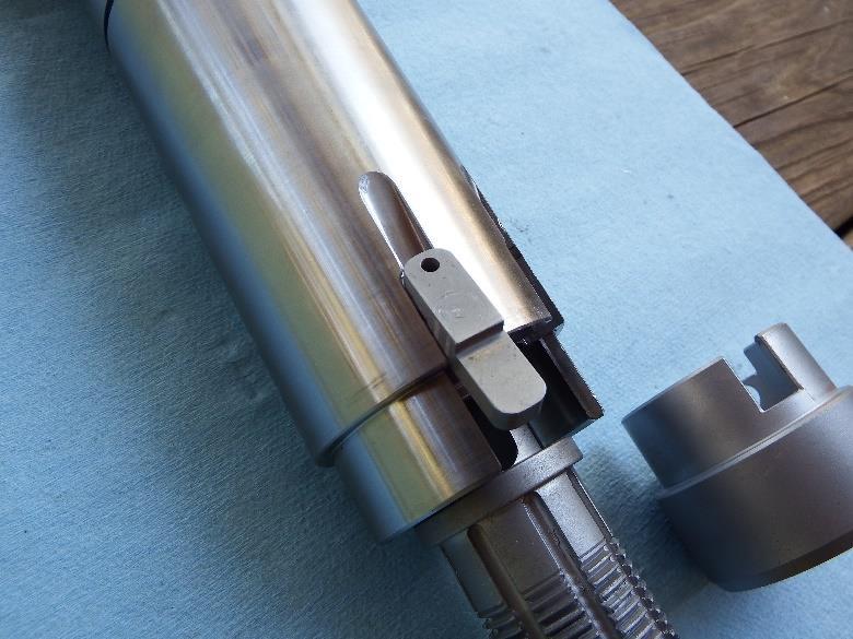
35 Pg. 35 of Ensure that the wires are tucked down in the Actuator. Insert the aluminum Gate into the upper slot in the Actuator. Ensure that the wires are not pinched by the Gate or at risk of pinching or damage from the Coupling Sleeve. Do not use the older large slot Aluminum Gates or the Teflon Gates. They will not properly restrain the Detonator and can result in the Hydrostatic Equalizing Plug not shearing and the Release Collar not opening. 25. Grease the O-rings and put High Temperature Anti-Seize on the threads of the Actuator. Put grease on the outside of the Fishing Neck where the internal O-rings on the Coupling Sleeve will sit. High Temperature Anti-Seize is conductive. If excess amounts are used on the threads it is possible for some of the Anti-Seize to seep down into the tool and cause a short in an electrical circuit. 26. Grease the Coupling Sleeve internal O-rings. Slide the Coupling Sleeve over the Fishing Neck and onto the Actuator. Screw the Coupling Sleeve onto the Actuator and bump it. Do not overtighten. 27. Change the 008 O-ring on the Hydrostatic Equalizing Plug. Carefully inspect the Hydrostatic Equalizing Plug and the sealing surfaces in the Coupling Sleeve. Grease the O-ring and put High Temperature Anti-Seize on the threads of the Hydrostatic Equalizing Plug. Install the Hydrostatic Equalizing Plug in the Coupling Sleeve. Snug it down with a Screwdriver.
36 Pg. 36 of 77 Never Turn the Coupling Sleeve without first removing the Hydrostatic Equalizing Plug! Attempting to remove the Coupling Sleeve without first removing the Hydrostatic Equalizing Plug will shear the Hydrostatic Equalizing Plug and can result in the tool running wet! 28. Put grease on the O-rings on the Fishing Neck and High Temperature Anti-Seize on the threads of the Fishing Neck. Screw the Quick Change Adapter onto the bottom of the Fishing Neck. Tighten the Quick Change Adapter to the Fishing Neck with 24 Pipe Wrenches. High Temperature Anti-Seize is conductive. If excess amounts are used on the threads it is possible for some of the Anti-Seize to seep down into the tool and cause a short in an electrical circuit.
37 Pg. 37 of The tool has been redressed. It is ready for storage or preparation for a run Routine Rebuilding the Addressable Disconnect Tool Model DE: Note that the recommended routine rebuilding of this tool involves the replacement of O-rings, checking of electrical connections, and inspection of parts. Repair or replace any parts showing signs of wear or damage. Any sub that does not pass an electrical check will need to be rebuilt with appropriate parts. This is the recommended best practice for the rebuilding of this tool. This represents the Manufacturer s recommendation and results in the most efficient and effective assembly of the tool. Never tighten through the assembled Addressable Disconnect Tool! This will cause catastrophic failure! Never attempt to remove the Coupling Sleeve without first removing the Hydrostatic Equalizing Plug! This can damage the HEP and cause a misrun. The Releasing Collar Assembly is sold as a unit and not as individual pieces. Do Not disassemble the Releasing Collar Assembly! High Temperature Anti-Seize is conductive. If excess amounts are used on the threads it is possible for some of the Anti-Seize to seep down into the tool and cause a short in an electrical circuit. 1. Following all Service Company Explosive Safety policies, the Detonator can be removed. 2. Remove the Hydrostatic Equalizing Plug from the Coupling Sleeve and discard it.
38 Pg. 38 of Unscrew the Coupling Sleeve from the Actuator and slide it down. The Quick Change Adapter will stop it from coming off the tool, but will leave enough room to remove the Detonator. 4. Remove the Gate from the Actuator. 5. Pull the Detonator out of the Actuator and place it in the Safety Tube. 6. Disconnect Blue Wire from the CCL Adapter to the Red Wire from the Detonator. Strip some insulation from the Red Detonator Wire to allow shunting the detonator. 7. Disconnect the Black Detonator Ground Wire from the two Ground Lugs on the Actuator. The Grounding Lugs can be replaced as necessary. 8. Shunt the Red and Black Wires on the Detonator together.


39 Pg. 39 of Disconnect the Blue Wire from the Fishing Neck from the Blue Through Wire from the DynaEnergetics DynaSelect Detonator. 10. The Detonator can now be removed from the Safety Tube and prepared for transport back to the Service Company shop as per the Service Company s Explosive Operations Procedures and in accordance with Federal and State Regulations. 11. Remove the Quick Change Adapter from the Fishing Neck and inspect the bottom of the Fishing Neck and both ends of the Quick Change Adapter. 12. Replace the 222 O-rings on the Fishing Neck. 13. Remove the Coupling Sleeve from the tool. Inspect the Coupling Sleeve. Replace the 226 O-rings that are inside the Coupling Sleeve. Put grease on the 226 O- rings.
40 Pg. 40 of Replace the 227 O-rings on the Actuator, inspecting the O-ring grooves and the threads of the Actuator in the process. 15. Remove the Brass Screw from the Actuator and discard it. 16. Replace the two Stainless Steel Ground Screws on the Actuator as needed. 17. Remove the Fishing Neck from the Actuator by holding backup on the Spline Nut with a 24 Pipe Wrench while loosening the Fishing Neck with another 24 Pipe Wrench. Ensure that the Pipe Wrench only contacts the Fishing Neck in the knurled area near the bottom of the Fishing Neck. Loosen Here Back Up Here 18. Pull the Kemlon Boot and Blue Wire out of the bottom of the Actuator if they did not come out with the Fishing Neck. Inspect the Kemlon Boot and Blue Wire and replace as needed. 19. Back off the Slide Stud Adapter Assembly from the Actuator by turning the Spline Nut.
41 Pg. 41 of Check the internal threads of the Actuator to make sure that any residual Loctite has been cleaned up. Use a 7/8 14 NF Tap to clean up the threads. 21. The Spline Nut will be reused so set it aside. Inspect the Release Collar, Shear Ring, and Slide Stud Adapter for damage or cracks especially the Release Collar. Check the gap between the Release Collar and the Slide Stud Adapter to ensure it is between and If it falls outside of this range or it exhibits any signs of cracking or damage, discard and replace.

42 Pg. 42 of 77 Inspect especially here for cracking. Inspect threads for damage. Inspect threads for damage. Gap must be between and Place the Actuator in the vise. Orient the Actuator such that the Key is at 12 o clock and the top of the Actuator is secured tightly in the vise. 23. If the Key is in place, remove it by prying it out with a small screwdriver. 24. Put Blue Loctite 242 on the threads of the Releasing Collar Assembly and screw it into the bottom of the Actuator by hand until the flange on the bottom of the Slide Stud Adapter is close to the bottom of the Actuator.
43 Pg. 43 of Place the Spline Nut on the Slide Stud Adapter and slowly screw the assembly into the Actuator while keeping pressure on the Spline Nut. Stop when the Spline Nut is in contact with the Actuator. Note that the Slide Stud Releasing Collar Assembly will not be tight with the Actuator. This is normal.
44 Pg. 44 of Remove the Spline Nut and put it back on trying to align the single slot with one of the two available keyways on the Actuator. Do not back off the assembly in this process. Turn only to the right.
45 Pg. 45 of Once the Spline Nut is aligned with a keyway, insert the key in the appropriate keyway. It will need to be tapped into place with a hammer. Ensure that the Key is flush with the Actuator. This process may be easier with the Spline Nut removed. After getting the key installed, replace the Spline Nut. The Spline Nut should be locked in and unable to turn. The Spline Nut must be against the Actuator.
46 Pg. 46 of Release the Actuator from the vise and rotate it 180 degrees such that the Key is on the underside of the Actuator. Tighten the vise. 29. Push the Shearing Collar up into the Actuator. Screw a Brass Shear Screw into the Actuator and snug it into place. This holds the Shearing Collar in place. 30. Coat the threads of the Slide Stud Adapter with High Temperature Anti-Seize. 31. Replace the Kemlon Boot with the Blue Wire at the top of the Fishing Neck.
47 Pg. 47 of Run the wire from the top of the fishing neck into the bottom of the Slide Stud Adapter. Fish the wire out of the Actuator Assembly below the Shearing Collar. 33. Thread the Fishing Neck onto The Slide Stud Adapter. Make up the Fishing Neck until hand tight against the Spline Nut which must be tight against the Actuator. Ensure that the Blue Wire from the Fishing neck does not get pinched. The Blue Wire may not turn with the tightening of the Fishing Neck as the Boot will catch in the Slide Stud Adapter. This is normal.
48 Pg. 48 of Use a 24 Pipe Wrench to hold backup on the Spline Nut. Place the other 24 Pipe Wrench on the Fishing Neck at the knurled area near the bottom of the Fishing Neck. Tighten the Fishing Neck onto the Actuator Assembly. After tightening, use a file to remove any tool marks from the Spline Nut. Tighten here Backup here 35. Measure and cut 1/8 Teflon Tubing that will extend from the Slide Stud Adapter through the hole in the Actuator housing. Then slide the tubing through the hole from above and feed the Blue Wire from the Fishing Neck through the tubing.
49 Pg. 49 of 77
50 Pg. 50 of 77 Older Actuators will not have hole through the Actuator, rather they will have a groove in the Actuator housing. Three Nylon Screws will be used to hold the tubing in the groove after the wire is run through the tubing and it is laid in the groove. Take a file to the three Nylon Screws to make them flush with the Actuator body. 36. Remove the CCL Adapter from the Actuator being careful not to damage the Blue Wire. Remove the O-rings from the CCL Adapter. Inspect the CCL Adapter O- ring grooves and threads. Replace the 227 and 222 O-rings. 37. Remove and carefully inspect the Kemlon Boot and Wire and PEEK Kemlon Retainer attached to the bottom of the CCL Adapter. Replace components as necessary. 38. Make up the Kemlon Boot and Wire to the bottom of the CCL Adapter. The Kemlon Boot is packed with grease. Work the Boot to ensure that there are no air pockets in the Boot and that it is properly seated on the Kemlon connector. Slide the PEEK Kemlon Retainer on the wire and over the Kemlon Boot. The 113 O- ring in the CCL Adapter will hold the PEEK Kemlon Retainer. 39. Grease the O-rings lightly and use High Temperature Anti-Seize on the threads of the CCL Adapter. High Temperature Anti-Seize is conductive. If excess amounts are used on the threads it is possible for some of the Anti-Seize to seep down into the tool and cause a short in an electrical circuit. 40. Feed the Blue Wire into the center hole at the top of the Actuator. Do Not Use offset hole for wire from CCL Adapter. Use Center Hole for wire from CCL Adapter.
51 Pg. 51 of Screw the CCL Adapter into the top of the Actuator while keeping light tension on the Blue Wire. Tighten the CCL Adapter to the Actuator with 24 Pipe Wrenches. Ensure that the Blue Wire is not pinched between the PEEK Kemlon Retainer and the Actuator. 42. Use a Digital Multimeter to check the through connection from the bottom of the Fishing Neck to the Blue Wire inside of the Actuator. Check for both continuity and leakage. A Megger can also be used to check for leakage since there are no explosives present. Never use a Multimeter or a Megger to check an Addressable Disconnect Tool if either an electronic switch or explosives are in the tool! 43. Use a Digital Multimeter to check the connection from the end of the blue wire in the Actuator to the top of the CCL Adapter. Check for both continuity and leakage. A Megger can also be used to check for leakage since there are no explosives present. 44. Insert the aluminum Gate into the upper slot on the Actuator. Do not pinch the wires with the Gate. Do not use the older large slot Aluminum Gates or the Teflon Gates. They will not properly restrain the Detonator and can result in the Hydrostatic Equalizing Plug not shearing and the Release Collar not opening. 45. Coil up the excess Wires and ensure that all the wires are tucked down in the Actuator. They must not be pinched by the Gate or near the surface of the Actuator where they could be pinched or damaged by the Coupling Sleeve.
52 Pg. 52 of Grease the O-rings and put High Temperature Anti-Seize on the threads of the Actuator. Put grease on the outside of the Fishing Neck where the internal O-rings on the Coupling Sleeve will sit. High Temperature Anti-Seize is conductive. If excess amounts are used on the threads it is possible for some of the Anti-Seize to seep down into the tool and cause a short in an electrical circuit. 47. Grease the Coupling Sleeve internal O-rings. Slide the Coupling Sleeve over the Fishing Neck and onto the Actuator. Screw the Coupling Sleeve onto the Actuator and bump it. Do not overtighten. 48. Put the 008 O-ring on the Hydrostatic Equalizing Plug. Carefully inspect the Hydrostatic Equalizing Plug and the sealing surfaces in the Coupling Sleeve. Grease the O-ring and put High Temperature Anti-Seize on the threads of the Hydrostatic Equalizing Plug. Install the Hydrostatic Equalizing Plug in the Coupling Sleeve. Snug it down with a Screwdriver. Never Turn the Coupling Sleeve without first removing the Hydrostatic Equalizing Plug! Attempting to remove the Coupling Sleeve without first removing the Hydrostatic Equalizing Plug will shear the Hydrostatic Equalizing Plug and can result in the tool running wet!
53 Pg. 53 of Put grease on the O-rings on the Fishing Neck and High Temperature Anti-Seize on the threads of the Fishing Neck. Screw the Quick Change Adapter onto the bottom of the Fishing Neck. Tighten the Quick Change Adapter to the Fishing Neck with 24 Pipe Wrenches. 50. The tool has now been rebuilt Rebuilding the Addressable Disconnect Tool Model DE After Release or Wet Run: Note that the rebuilding of tools that have released or run wet involves the replacement of O-rings, checking of electrical connections, and inspection of parts. Repair or replace any parts showing signs of wear or damage. The Release Assembly will be replaced. Any sub that does not pass an electrical check will need to be rebuilt with appropriate parts. This is the recommended best practice for the rebuilding of this tool. This represents the Manufacturer s recommendation and results in the most efficient and effective assembly of the tool. Never tighten through the assembled Addressable Disconnect Tool! This will cause catastrophic failure! Never attempt to remove the Coupling Sleeve without first removing the Hydrostatic Equalizing Plug! This can damage the HEP and cause a misrun. The Releasing Collar Assembly is sold as a unit and not as individual pieces. Do Not disassemble the Releasing Collar Assembly! 1. Remove the Hydrostatic Equalizing Plug from the Coupling Sleeve and discard it.

54 Pg. 54 of 77 Note the difference between a new HEP, an HEP sheared as a result of a release, and an HEP sheared by turning the Coupling Sleeve. 2. Unscrew the Coupling Sleeve from the Actuator and slide it down and off the Actuator. 3. Remove the Gate from the Actuator and discard it. The gates are not to be reused after firing the release Detonator. Note how the Gate has been damaged and spread by the firing of the Detonator.

55 Pg. 55 of Pull the carcass of the Detonator out of the Actuator and proceed to step (11). If the Detonator has not fired proceed to step (5). 5. Pull the Detonator out of the Actuator and place it in the Safety Tube. 6. Disconnect Blue Wire from the CCL Adapter to the Red Wire from the Detonator. Strip some insulation from the Red Detonator Wire to allow shunting the detonator. 7. Disconnect the Black Detonator Ground Wire from the two Ground Lugs on the Actuator. The Grounding Lugs can be replaced as necessary. 8. Shunt the Red and Black Wires on the Detonator together. 9. Disconnect the Blue Wire from the Fishing Neck from the Blue Through Wire from the DynaEnergetics DynaSelect Detonator. 10. The Detonator can now be removed from the Safety Tube and prepared for transport back to the Service Company shop as per the Service Company s Explosive Operations Procedures and in accordance with Federal and State Regulations. Proceed to step (15). 11. Disconnect Blue Wire from the CCL Adapter to the Red Wire on the Detonator carcass. 12. Disconnect the Black Detonator Ground Wire from the two Ground Lugs on the Actuator. The Grounding Lugs can be replaced as necessary. 13. Disconnect the Blue Wire from the Fishing Neck from the Blue Wire from the Detonator carcass. 14. The carcass of the Detonator can now be discarded. 15. If the Fishing Neck has been recovered, remove the Quick Change Adapter from the Fishing Neck and inspect both ends of the Quick Change Adapter. Check the Quick Change Adapter with a Digital Multimeter. Rebuild the Quick Change Adapter as necessary.
56 Pg. 56 of Inspect the Fishing Neck very carefully. If the 2 Fishing Neck has been fished, it could be deeply scored by the overshot. The scoring can damage the internal O- rings on the Coupling Sleeve or simply cause them not to make a seal which could cause the tool to run wet. Replace the Fishing Neck as necessary. 17. Break out and remove the Slide stud assembly from the top of the Fishing Neck. Keep the Spline Nut and discard the Slide Stud Assembly. Discard the Kemlon Boot and remains of the Blue Wire. Carefully inspect the threads on both ends of the Fishing Neck. Check the Fishing Neck with a Digital Multimeter. Rebuild or replace the Fishing Neck as necessary. 18. Use a deep ¼ socket to remove the Kemlon connection at the top of the Fishing Neck. Change the Duro Viton O-ring and reinstall the Kemlon Connection. Check the Fishing Neck with a Digital Multimeter. 19. Replace the 222 O-rings on the Fishing Neck. 20. Inspect the Coupling Sleeve. Replace the 226 O-rings that are inside the Coupling Sleeve. Put grease on the 226 O-rings. 21. Replace the 227 O-rings on the Actuator, inspecting the O-ring grooves and the threads of the Actuator in the process. 22. Remove the Brass Screw from the Actuator and discard it. 23. Back off the Release Collar from the Actuator using an Irwin #6 spiral Easy Out and discard. Clean the internal threads of the Actuator with a 7/8 14 NF Tap.


57 Pg. 57 of Place the Actuator in the vise. Orient the Actuator such that the Key is at 12 o clock and the top of the Actuator is secured tightly in the vise. 25. If the Key is in place, remove it by prying it out with a small screwdriver. 26. Put Blue Loctite 242 on the threads of the Releasing Collar Assembly and screw it into the bottom of the Actuator by hand until the flange on the bottom of the Slide Stud Adapter is close to the bottom of the Actuator. 27. Place the Spline Nut on the Slide Stud Adapter and slowly screw the assembly into the Actuator while keeping pressure on the Spline Nut. Stop when the Spline


58 Pg. 58 of 77 Nut is in contact with the Actuator. Note that the Slide Stud Releasing Collar Assembly will not be tight with the Actuator. This is normal. 28. Remove the Spline Nut and put it back on trying to align the single slot with one of the two available keyways on the Actuator. Do not back off the assembly in this process. Turn only to the right.


59 Pg. 59 of Once the Spline Nut is aligned with a keyway, insert the key in the appropriate keyway. It will need to be tapped into place with a hammer. Ensure that the Key is flush with the Actuator. This process may be easier with the Spline Nut removed. After getting the key installed, replace the Spline Nut. The Spline Nut should be locked in and unable to turn. The Spline Nut must be against the Actuator.

60 Pg. 60 of 77


61 Pg. 61 of Release the Actuator from the vise and rotate it 180 degrees such that the Key is on the underside of the Actuator. Tighten the vise. 31. Push the Shearing Collar up into the Actuator. Screw a Brass Shear Screw into the Actuator and snug it into place. This holds the Shearing Collar in place. Use only the Brass Screws from ICSI as they have been turned down to reduce the required shear force. 32. Coat the threads of the Slide Stud Adapter with High Temperature Anti-Seize. 33. Replace the Kemlon Boot with the Blue Wire at the top of the Fishing Neck. The Boot is packed with grease. Ensure that the Boot is properly seated on the Kemlon Connection and it has been worked to get any air pockets out.


62 Pg. 62 of Run the wire from the top of the fishing neck into the bottom of the Slide Stud Adapter. Fish the wire out of the Actuator Assembly below the Shearing Collar. 35. Thread the Fishing Neck onto The Slide Stud Adapter. Make up the Fishing Neck until hand tight against the Spline Nut which must be tight against the Actuator. Ensure that the Blue Wire from the Fishing neck does not get pinched. The Blue Wire may not turn with the tightening of the Fishing Neck as the Boot will catch in the Slide Stud Adapter. This is normal.

63 Pg. 63 of Use a 24 Pipe Wrench to hold backup on the Spline Nut. Place the other 24 Pipe Wrench on the Fishing Neck at the knurled area near the bottom of the Fishing Neck. Tighten the Fishing Neck onto the Actuator Assembly. After tightening, use a file to remove any tool marks from the Spline Nut. Tighten here Backup here 37. Measure and cut 1/8 Teflon Tubing that will extend from the Slide Stud Adapter through the hole in the Actuator housing. Then slide the tubing through the hole from above and feed the Blue Wire from the Fishing Neck through the tubing.

64 Pg. 64 of 77
65 Pg. 65 of 77 Older Actuators will not have hole through the Actuator, rather they will have a groove in the Actuator housing. Three Nylon Screws will be used to hold the tubing in the groove after the wire is run through the tubing and it is laid in the groove. Take a file to the three Nylon Screws to make them flush with the Actuator body. 38. Remove the CCL Adapter from the top of the Actuator. Remove the PEEK Kemlon Retainer and the Kemlon Boot and Blue Wire and discard. Remove all the O-rings from the CCL Adapter. Inspect the CCL Adapter O-ring grooves and threads. Replace the 227 O-rings and the 222 O-rings. 39. Use a ¼ deep socket to remove the Kemlon Connection Pins. Replace the Duro Viton O-ring. The 003 O-ring on the small pin end of the Kemlon Connection Pin is there to contain broken pieces of ceramic from the Kemlon Connection Pin. The ceramic near the small pin breaks when shooting guns. If the ceramic is intact, the 003 O-ring can be replaced. If the ceramic is already broken, clean out the broken pieces and continue without it. Reinstall the Kemlon Connection Pin. 40. Replace the Kemlon Boot and Wire attached to the bottom of the CCL Adapter. The Kemlon Boots are packed with grease. Ensure that the Kemlon Boots are fully seated and that there are no air pockets inside the Boots. Slide the PEEK Kemlon Retainer over the Blue Wire and down until it fits over the Boot. The 113 O-ring in the CCL Adapter will hold the PEEK Kemlon Retainer. 41. Grease the O-rings lightly and lightly coat the threads of the CCL Adapter with High Temperature Anti-Seize. High Temperature Anti-Seize is conductive. If excess amounts are used on the threads it is possible for some of the Anti-Seize to seep down into the tool and cause a short in an electrical circuit. 42. Feed the Blue Wire into the center hole at the top of the Actuator.

66 Pg. 66 of 77 Do Not Use offset hole for wire from CCL Adapter. Use Center Hole for wire from CCL Adapter. 43. Screw the CCL Adapter into the top of the Actuator while keeping light tension on the Blue Wire. Tighten the CCL Adapter to the Actuator with 24 Pipe Wrenches. Ensure that the Blue Wire is not pinched between the PEEK Kemlon Retainer and the Actuator. 44. Use a Digital Multimeter to check the through connection from the bottom of the Fishing Neck to the Blue Wire inside of the Actuator. Check for both continuity and leakage. A Megger can also be used to check for leakage since there are no explosives present. Never use a Multimeter or a Megger to check an Addressable Disconnect Tool if either an electronic switch or explosives are in the tool! 45. Use a Digital Multimeter to check the connection from the end of the blue wire in the Actuator to the top of the CCL Adapter. Check for both continuity and leakage. A Megger can also be used to check for leakage since there are no explosives present. 46. Insert the aluminum Gate into the upper slot on the Actuator. Do not pinch the wires with the Gate. Do not use the older large slot Aluminum Gates or the Teflon Gates. They will not properly restrain the Detonator and can result in the Hydrostatic Equalizing Plug not shearing and the Release Collar not opening.

67 Pg. 67 of Coil up the excess Wires and ensure that all the wires are tucked down in the Actuator. They must not be pinched by the Gate or near the surface of the Actuator where they could be pinched or damaged by the Coupling Sleeve. High Temperature Anti-Seize is conductive. If excess amounts are used on the threads it is possible for some of the Anti-Seize to seep down into the tool and cause a short in an electrical circuit. 48. Grease the O-rings and put High Temperature Anti-Seize on the threads of the Actuator. Put grease on the outside of the Fishing Neck where the internal O-rings on the Coupling Sleeve will sit. 49. Grease the Coupling Sleeve internal O-rings. Slide the Coupling Sleeve over the Fishing Neck and onto the Actuator. Screw the Coupling Sleeve onto the Actuator hand tight. 50. Put the 008 O-ring on the Hydrostatic Equalizing Plug. Carefully inspect the Hydrostatic Equalizing Plug and the sealing surfaces in the Coupling Sleeve. Grease the O-ring and put High Temperature Anti-Seize on the threads of the Hydrostatic Equalizing Plug. Install the Hydrostatic Equalizing Plug in the Coupling Sleeve. Snug it down with a Screwdriver.
68 Pg. 68 of 77 Never Turn the Coupling Sleeve without first removing the Hydrostatic Equalizing Plug! Attempting to remove the Coupling Sleeve without first removing the Hydrostatic Equalizing Plug will shear the Hydrostatic Equalizing Plug and can result in the tool running wet! 51. Put grease on the O-rings on the Fishing Neck and High Temperature Anti-Seize on the threads of the Fishing Neck. Screw the Quick Change Adapter onto the bottom of the Fishing Neck. Tighten the Quick Change Adapter to the Fishing Neck with 24 Pipe Wrenches. High Temperature Anti-Seize is conductive. If excess amounts are used on the threads it is possible for some of the Anti-Seize to seep down into the tool and cause a short in an electrical circuit. 52. The tool has now been rebuilt Rebuilding the Addressable Disconnect Tool Model DE Quick Change Adapter: Any sub that does not pass an electrical check will need to be rebuilt with appropriate parts. Subs may be rebuilt at periodic intervals as a preventative measure. The intervals are at the discretion of the local Wireline Company Management. Note that the rebuilding of subs involves the replacement of O-rings, checking of electrical connections, and inspection of parts. Repair or replace any parts showing signs of wear or damage. This is the recommended best practice for the rebuilding of this tool. This represents the Manufacturer s recommendation and results in the most efficient and effective assembly of the tool. Never tighten through the assembled Addressable Disconnect Tool! This will cause catastrophic failure! Never attempt to remove the Coupling Sleeve without first removing the Hydrostatic Equalizing Plug! This can damage the HEP and cause a misrun. The Releasing Collar Assembly is sold as a unit and not as individual pieces. Do Not disassemble the Releasing Collar Assembly! 1. Disassemble the Addressable Disconnect Tool in accordance with this manual.

69 Pg. 69 of The Quick Change Adapter can be disassembled by using two 3/8 Sockets with ratchets or 3/8 Nut Drivers or a combination of these tools. Insert the tools into each end of the Quick Change Adapter and onto the respective Contacts. Loosen one while holding back up on the other. 3. One Contact will come out while the other will come out with the Through Rod. The Through Rod will typically bring out the Insulator Washer from its end and the Teflon Tubing on the Rod. The Insulator Washer at the other end will either fall out or can be recovered with a pick. 4. Typically, the Insulator Washers and Teflon Tubing will be replaced. 5. To reassemble the Sub, place the Insulator Washer on the Rod with the flat side towards the Contact. Slide the Teflon Tubing over the Rod and under the Insulator Washer. Insert the Assembly into one end of the Quick Change Adapter. 6. Hold the Contact Rod Assembly in place with a 3/8 Socket. 7. Insert an Insulator Washer into the other end of the Quick Change Adapter. Ensure that the flat side of the Insulator Washer is facing the end of the Quick Change Adapter. 8. Place the remaining Contact into the other 3/8 Socket and screw it onto the Contact Rod Assembly. 9. Tighten the Contacts. 10. Check for continuity and leakage with a digital multimeter. The Quick Change Adapter can also be check with a Megger for leakage.
70 Pg. 70 of Rebuilding the Addressable Disconnect Tool Model DE CCL Adapter: Any sub that does not pass an electrical check will need to be rebuilt with appropriate parts. Subs may be rebuilt at periodic intervals as a preventative measure. The intervals are at the discretion of the local Wireline Company Management. Note that the rebuilding of subs involves the replacement of O-rings, checking of electrical connections, and inspection of parts. Repair or replace any parts showing signs of wear or damage. This is the recommended best practice for the rebuilding of this tool. This represents the Manufacturer s recommendation and results in the most efficient and effective assembly of the tool. Never tighten through the assembled Addressable Disconnect Tool! This will cause catastrophic failure! Never attempt to remove the Coupling Sleeve without first removing the Hydrostatic Equalizing Plug! This can damage the HEP and cause a misrun. The Releasing Collar Assembly is sold as a unit and not as individual pieces. Do Not disassemble the Releasing Collar Assembly! 1. Disassemble the Addressable Disconnect Tool in accordance with this manual. 2. The CCL Adapter can be disassembled by using an O-ring pick to remove the 113 O-ring that retains the Kemlon Bulkhead Adapter at the bottom of the CCL Adapter. Use the O-ring pick to remove the 113 O-ring retaining the Contact Pin and Insulator at the top of the CCL Adapter. Do this carefully as the Insulator and Contact Pin are under spring tension. 3. Pull on the Contact Pin and the Contact Pin Assembly will come out of the CCL Adapter. The Assembly consists of the Contact Pin, Copper Beryllium Spring, Contact, Insulator, Insulator Washer, Through Rod with Female Kemlon Connection, and Teflon Tubing. New CCL Adapters use Copper Beryllium Springs to reduce the resistivity of the tool string. Contact ICSI for replacement Copper Beryllium Springs. 4. The CCL Adapter can be further disassembled by using a 1/4 Deep Socket with ratchet and extension or 1/4 Deep Nut Driver. Use the tool to remove the Kemlon Connector at the bottom end of the CCL Adapter. 5. Use a punch to push the Kemlon Bulkhead Adapter out of the CCL Adapter. 6. Typically, the Insulator, Insulator Washer, and Teflon Tubing will be replaced.
71 Pg. 71 of Replace the 204 O-rings on the Kemlon Bulkhead Adapter. 8. To reassemble the Sub, push the Kemlon Bulkhead Adapter into the bottom of the CCL Adapter. The beveled end goes into the CCL Adapter. 9. Install the 113 O-ring in the bottom end of the CCL Adapter. 10. Use a 1/4 Deep Socket with ratchet and extension or 1/4 Deep Nut Driver. Use the tool to install the Kemlon Connector in the Kemlon Bulkhead Adapter at the bottom end of the CCL Adapter. 11. Place the Insulator Washer on the Rod with the flat side towards the Contact. Slide the Teflon Tubing over the Rod and under the Insulator Washer. 12. Push and twist the Copper Beryllium Spring onto the Contact. 13. Push and twist the Copper Beryllium Spring onto the Contact Pin. 14. Slide the Insulator over the Contact Pin. 15. Insert the Assembly into the top end of the CCL Adapter. 16. Push the Contact Pin and Insulator into the CCL Adapter far enough to push the 113 O-ring into the opening and into the O-ring groove. 17. Check for continuity and leakage with a digital multimeter. The CCL Adapter can also be check with a Megger for leakage Rebuilding the Addressable Disconnect Tool Model DE Fishing Neck: Any sub that does not pass an electrical check will need to be rebuilt with appropriate parts. Subs may be rebuilt at periodic intervals as a preventative measure. The intervals are at the discretion of the local Wireline Company Management. Note that the rebuilding of subs involves the replacement of O-rings, checking of electrical connections, and inspection of parts. Repair or replace any parts showing signs of wear or damage. This is the recommended best practice for the rebuilding of this tool. This represents the Manufacturer s recommendation and results in the most efficient and effective assembly of the tool. Never tighten through the assembled Addressable Disconnect Tool! This will cause catastrophic failure! Never attempt to remove the Coupling Sleeve without first removing the Hydrostatic Equalizing Plug! This can damage the HEP and cause a misrun.

72 Pg. 72 of 77 The Releasing Collar Assembly is sold as a unit and not as individual pieces. Do Not disassemble the Releasing Collar Assembly! 1. Disassemble the Addressable Disconnect Tool in accordance with this manual. 2. Remove and discard the Boot and Wire from the top of the Fishing Neck. 3. Using a ¼ Deep Socket unscrew the Kemlon Contact Pin from the top of the Fishing Neck. Inspect the Kemlon Contact Pin and replace as necessary. 4. Change the 008 Viton 70 Duro O-ring on the Kemlon Contact Pin. The 003 O- ring on the small pin end of the Kemlon Connection Pin is there to keep broken pieces of ceramic from the Kemlon Connection Pin together. The ceramic near the small pin breaks when shooting guns. If the ceramic is intact, the 003 O-ring can be replaced. If the ceramic is already broken, clean out the broken pieces and continue without it. 5. Use a pick to remove the 113 O-ring holding the Insulator and Contact Pin in the bottom of the Fishing Neck. Be careful as the Contact Pin and Insulator are under spring tension. 6. Pull out the Contact Pin Assembly from the bottom of the Fishing Neck. The Contact Pin, Insulator, Copper Beryllium Spring, Insulator Washer, Contact, Contact Rod with Teflon Tubing will all come out together. It may be necessary to fish out the Insulator Washer with a pick. There is a Kemlon Connection Box on the end of the Contact Rod. Inspect the Assembly and replace components as necessary.

73 Pg. 73 of Reinsert the Assembly into the bottom of the Fishing Neck. Compress the Contact Pin and Insulator enough to insert the 113 O-ring into the O-ring groove to retain the Insulator. 8. Using a ¼ Deep Socket screw the Kemlon Contact Pins into the top of the Fishing Neck and tighten it. 9. Push a new Boot with a Blue Wire onto the Kemlon Contact Pin. The Boots are packed with grease. They must be worked onto the pins to get out any trapped air and to ensure they are on securely. 10. Check the Fishing Neck for leakage and continuity with a digital multimeter. Continued Next Page
Discount-Equipment.com
 REQUIRED TOOLS LS Series Remix Shaft Installation Instructions /8", /6", /2" Allen Wrenches Snap Ring Pliers (Light Duty) /" Combination Wrench Loctite #22 Blue /" Socket w/ /8" Ratchet Electric Drill
#10 Setting Tool Assembly Product Family No (10)
") BRICO Oil Tools provides a dependable line of Wireline Pressure Setting Tools for the Wireline industry worldwide. Our engineering, high quality and service provides a cost effective alternative. BT#10
BRICO Oil Tools provides a dependable line of Wireline Pressure Setting Tools for the Wireline industry worldwide. Our engineering, high quality and service provides a cost effective alternative. BT#10
Discount-Equipment.com
 LS40D, LS40TD, LS50TD, LS60TD LS-Series Remix Shaft Coupler Retrofit Kit Installation Instructions The following instructions are intended to assist the user in the installtion of the LS-Series Remix Shaft
Mandatory X Information Recommended Change. Series/Parts Affected: LS40D, LS40TD, LS50TD and LS60TD Concrete Pumps
 Service Bulletin No. CP20060428 Subject: Remix Shaft Coupler Retrofit Kit Model: LS40D, LS40TD, LS50TD & LS60TD Product Group: Concrete Pump Date: April 28, 2006 SERVICE BULLETIN Group: CP Mandatory X
Installation Instructions COMPETITION/PLUS SHIFTER Ford Mustang MT82 6-Speed Manual Transmission Catalog#
 Installation Instructions COMPETITION/PLUS SHIFTER 2015-2017 Ford Mustang MT82 6-Speed Manual Transmission Catalog# 3916037 Rev. 00 WORK SAFELY! For maximum safety, perform this installation on a clean,
LS Series. Remix Shaft Installation Instructions REQUIRED TOOLS PARTS WORK SAFELY! PREPARATION/SAFETY PROCEDURES
 REQUIRED TOOLS LS Series Remix Shaft Installation Instructions /8", /6", /2" Allen Wrenches Snap Ring Pliers (Light Duty) /" Combination Wrench Loctite #22 Blue /" Socket w/ /8" Ratchet Electric Drill
Installation Manual TWM Performance Short Shifter Cobalt SS/SC, SS/TC, HHR SS, Ion Redline and Saab 9-3
 Page 1 Installation Manual TWM Performance Short Shifter Cobalt SS/SC, SS/TC, HHR SS, Ion Redline and Saab 9-3 Please Note: It is preferable to park on a flat surface, as you will have to engage and disengage
Installation Instructions
 Preparing your vehicle to install your brake system upgrade 1. Rack the vehicle. 2. If you don t have a rack, then you must take extra safety precautions. 3. Choose a firmly packed and level ground to
PNEUMATIC SLIDING VALVE
 INSTALLATION, OPERATION, & #: MM-SV001 6-23-09 Rev. A Page 1 of 8 PNEUMATIC SLIDING VALVE PART NUMBERS (Including, but not inclusive) SV704MSTS, SV714MSTS, SV754MSTS, SV764MSTS, SV774MSTS, SV706MSTS, SV716MSTS,
Fluid-O-Tech ROTOFLOW ROTARY VANE PUMP REBUILD MANUAL
 Fluid-O-Tech PUMP TECHNOLOGY AT ITS BEST WWW.FLUID-O-TECH.COM Office: 161 Atwater St., Plantsville, CT 06479 Phone: (860) 276-9270 Fax: (860) 620-0193 ROTOFLOW ROTARY VANE PUMP REBUILD MANUAL 08/09 Ed.,
Max IV Rear Axle Replacement For models after Serial Number and all rear splined axle replacements.
 Max IV Rear Axle Replacement For models after Serial Number 19089 and all rear splined axle replacements. 10/8/03 Max IV Snap Ring Rear Axle replacement.doc Tools required: 9/16 Wrench 6 Extension Steel
Gauge Assembly and Maintenance
 Gauge Assembly and Maintenance by Scott A. Ager 9-10-08 Gauge Sections Gauge Sections Sensor Section (M006) Bull Nose (C010) OWR Section (Gauge S/N) Attaches to Shock Mitigater Data Readout Section (C011)
Audi-Larm TM Audible Alarm: AirHawk II Air Mask
 Audi-Larm TM Audible Alarm: AirHawk II Air Mask MAINTENANCE AND REPAIR MSA 011 (L) Rev. 0 MSA 2010 Prnt. Spec. 10000005389(I) Mat. 10104323 Doc. 10104323 REPLACEMENT KITS AND PARTS LIST Item P/N Description
NeoProducts, LLC New Orleans, LA USA Ph:
 NeoHybridPositiveDisplacementBailer Systems General Preparation & Run-in Procedures (NeoHybridPDB Systems) Document # ********************************************************************************************
Cylinder and Valve: AirHawk II Air Mask
 Cylinder and Valve: AirHawk II Air Mask MAINTENANCE AND REPAIR MSA 011 (L) Rev. 0 MSA 2010 Prnt. Spec. 10000005389(I) Mat. 10104218 Doc. 10104218 Parts List Cylinder Replacement Kits Item P/N Description
First, check and record the camber and caster readings, they will be adjusted later.
 First, check and record the camber and caster readings, they will be adjusted later. The caliper-mounting bosses are machined perpendicular to the spindle so they are an excellent place for the level.
Next, set the bar level and tighten it down. Do this on both the driver and passenger sides.
 Next, set the bar level and tighten it down. Do this on both the driver and passenger sides. Using two tape measures, measure the outside width at the front and the rear of the tubes. The front dimension
SERVICE INSTRUCTIONS FOR SEAL REPLACEMENT OF POWER GEAR HYDRAULIC LEVELING LEGS
 SERVICE INSTRUCTIONS FOR SEAL REPLACEMENT OF POWER GEAR HYDRAULIC LEVELING LEGS 82-L0352 REV 8 4-27-2011 WARNING! HYDRAULIC COMPONENTS CAN CAUSE SERIOUS INJURY OR DEATH IF PROPER SAFETY PRECAUTIONS ARE
Next, chase the threads in the lower A-arm mounts with the 5/8-18 tap and blowout any remaining particles.
 Next, chase the threads in the lower A-arm mounts with the 5/8-18 tap and blowout any remaining particles. Now, apply some anti-seize to the threads of the pivot stud. Also put anti-seize inside the bore
PRESSURE RELIEF VALVE: DISASSEMBLY, INSPECTION, and ASSEMBLY CONTENTS
 Page 1 of 35 PRESSURE RELIEF VALVE: DISASSEMBLY, INSPECTION, and ASSEMBLY CONTENTS 1. Overview 2. Disassembly of Valves with Liner Subs and press-in Bushing (Models 30525 and 30550). 2.1. Routine Disassembly
Transmission Overhaul Procedures-Bench Service
 How to Assemble the Lower Reverse Idler Gear Assembly Special Instructions In 1996 Eaton changed the reverse idler system design. In the nut design, the reverse idler bearing was lubricated through a hole
DYNATRAC PRODUCTS V5.3
 DYNATRAC PRODUCTS V5.3 2000-2008 Dodge Hub Kit Stage 1 4x4, Front Axle Free Spin Conversion Kit Note: This Kit is not Approved for 2007 & up 3500 Cab and Chassis Trucks Due to a Larger U-Joint (If U-Joint
DrVanos.com Stage II Installation Instructions. Tool rental is available with the purchase of a vanos kit *See website for more info*
 DrVanos.com Stage II Installation Instructions Special Tools Needed: Camshaft locking tool TDC Crank pin Sprocket turning tool Tool rental is available with the purchase of a vanos kit *See website for
3M Overhaul Service Kit
 SERVICE INSTRUCTIONS FOR 3M 12,000 RPM 3 in. (77 mm) RANDOM ORBITAL SANDERS 3M Overhaul Service Kit The part number 20346, 3M Overhaul Service Kit, contains all the replacement parts that naturally wear
HYDRAULICS. TX420 & & lower. Hydraulic Tandem Pump Removal. 4. Remove the LH side panel (Fig. 0388).
.") TX420 & 425 240000299 & lower 4. Remove the LH side panel (Fig. 0388). Hydraulic Tandem Pump Removal Note: Cleanliness is a key factor in a successful repair of any hydraulic system. Thoroughly clean all
TX420 & 425 240000299 & lower 4. Remove the LH side panel (Fig. 0388). Hydraulic Tandem Pump Removal Note: Cleanliness is a key factor in a successful repair of any hydraulic system. Thoroughly clean all
#TL T EA888 GEN 3 FUELING SYSTEM/ INSTALLATION INSTRUCTIONS
 #TL100069 2.0T EA888 GEN 3 FUELING SYSTEM/ INSTALLATION INSTRUCTIONS Notes: These instructions were written for a North American specification MkVII GTI. Other models, like the Golf R, are similar. When
INSTALLATION INSTRUCTIONS
 INSTALLATION INSTRUCTIONS --1075 North Ave. Sanger, CA 93657-3539 local: 559-875-0222 fax: 559-876-2259 toll free: 800-445-3767-- 2505 Lowering Spindle Assembly Installation Instructions ½ TON SILVERADO
E31 Repair Procedure Replace Front Wheel Hub/Bearing Assembly
 E31 Repair Procedure 31-21 Replace Front Wheel Hub/Bearing Assembly Disclaimer This repair procedure is provided as is and is not authoritative with respect to any BMW repair operation. Mark F. Fling is
servicing the swivel
 servicing the swivel The swivel seals and bearings require periodic replacement. This document describes how to determine which service procedure to use to service the swivel assembly, part number 101110.
Throttling Pendulum Gate O-ring Replacement Procedure Rev. A, May 2012
 Throttling Pendulum Gate O-ring Replacement Procedure Rev. A, May 2012 This procedure covers the replacement of the gate O-ring of the Nor-Cal Pendulum Gate Valve, with the gate valve housing installed
WATTS LINK REAR SUSPENSION KIT
 WATTS LINK REAR SUSPENSION KIT INSTALLATION MANUAL: Saleen S-Series / H-Series / Mustang GT 05-09 Model Years P/N: -8002-C6859B Saleen Performance Inc. -800-888-8945 www.saleen.com STOP IF YOU ARE NOT
INSTRUCTIONS FOR REPLACING THE SEALS, SHAFT SUPPORT BUSHING AND SHAFT SUPPORT BEARING IN A MODEL PBF-50, 50S, & 100 PROPELLER WASHED BEAD FILTER
 May 28, 2008 INSTRUCTIONS FOR REPLACING THE SEALS, SHAFT SUPPORT BUSHING AND SHAFT SUPPORT BEARING IN A MODEL PBF-50, 50S, & 100 PROPELLER WASHED BEAD FILTER Parts for 7/8 Seal Replacement Kit (PBF-SK7/8)
1004D2/1005E API Bottom Loading Coupler. 1005E Small handles used throughout Europe 1004D
 PART #H32183PA February 2009 1004D2/1005E API Bottom Loading Coupler The 1004D2 is the standard in drip-less bottom loading couplers and a proven performer at major oil terminals worldwide. The 1004D2
Steeda S550 MT-82 Tri-Ax Race Short Throw Shifter Installation Instructions For Parts: ,
 Steeda S550 MT-82 Tri-Ax Race Short Throw Shifter Installation Instructions For Parts: 555-7317, 555-7318 Tools required 1. 7mm socket 2. 10mm socket 3. 13mm socket 4. 15mm socket 5. 18mm socket 6. 3/8
MM Rear Coil-Over Kit - Bilstein Shocks (MMCO-3)
") 3430 Sacramento Dr., Unit D San Luis Obispo, CA 93401 Telephone: 805/544-8748 Fax: 805/544-8645 www.maximummotorsports.com MM Rear Coil-Over Kit - Bilstein Shocks (MMCO-3) Read all instructions before
3430 Sacramento Dr., Unit D San Luis Obispo, CA 93401 Telephone: 805/544-8748 Fax: 805/544-8645 www.maximummotorsports.com MM Rear Coil-Over Kit - Bilstein Shocks (MMCO-3) Read all instructions before
Light Truck MegaShifter
 Installation Instructions Light Truck MegaShifter The B&M Light Truck Megashifter shifter is designed to be used in most light trucks equipped with most popular three speed or four speed automatic transmissions.
Installation Instructions Z-Gate Shifter
 Installation Instructions Z-Gate Shifter Part Number 80681 1998, 2001 by B&M Racing and Performance Products The B&M Z-Gate shifter can be used in vehicles equipped with most popular three speed automatic
Installation Notes: #86000-R Race Series +3.5 L/T Kit
 159 North Maple St. Unit J, CORONA CA 92880 P. 951-737-9682 F. 951-737-9006 WWW.CHAOSFAB.COM Installation Notes: #86000-R Race Series +3.5 L/T Kit Factory manual is recommended for removal and re-installation
Tooling Assistance Center
 Safeguards are designed into this application equipment to protect operators and maintenance personnel from most hazards during equipment operation. However, certain safety precautions must be taken by
Z-Gate Universal Shifter
 Installation Instructions Z-Gate Universal Shifter Fits: GM, Ford, Lincoln and Chrysler Transmissions See Application Guide for Specific Applications Part #80681 Rev 06/01/2018 WORK SAFELY! For maximum
INTERNAL CHEMICAL HYDRAULIC VALVE
 INSTALLATION, OPERATION, & #: MM-CH005 4-20-09 Rev. A Page of 7 INTERNAL CHEMICAL HYDRAULIC VALVE PART NUMBER CH47003SST INTERNAL CHEMICAL HYDRAULIC VALVE MM-CH005 Rev. A Page 2 of 7 Table of Contents.0
Steering Gearbox Disassembly
 Steering Gearbox Disassembly Steering Rack Disassembly 5. Unbend the lock washer. Before disassembling the gearbox, wash it off with solvent and a brush. Do not dip seals and O-rings in solvent. 1. Remove
(8) Perform negative-pressure check IAW paragraph (9) Install mask-mounted regulator in regulator holder.
 Perform negative-pressure check IAW paragraph (9) Install mask-mounted regulator in regulator holder.") (8) Perform negative-pressure check IAW paragraph 6.6.3. (9) Install mask-mounted regulator in regulator holder. 6.7.3.2 Mask-Mounted Regulator Removal and Installation. O-ring, PN 18002-00 Pliers, slip
(8) Perform negative-pressure check IAW paragraph 6.6.3. (9) Install mask-mounted regulator in regulator holder. 6.7.3.2 Mask-Mounted Regulator Removal and Installation. O-ring, PN 18002-00 Pliers, slip
TCI Trans-Scat
 Page 1 of 5 Return to Instruction Sheet index TCI 400000 Trans-Scat Turbo Hydramatic 400-1965-Up This kit will allow you to re-program your transmission valve body. This kit will give you firm positive
Maintenance Manual. Hydrant Coupler. F250 Series
 Hydrant Coupler F250 Series LIST OF EFFECTIVE PAGES On a revised page, the portion of text or illustrations affected by the change is indicated by a vertical line in the outer margin of the page. When
INSTALLATION GUIDE. Kawasaki KLR Manual Revision:
 REKLUSE MOTOR SPORTS The z-start Pro Clutch INSTALLATION GUIDE Kawasaki KLR650 191-640 Manual Revision: 030308 2007 Rekluse Motor Sports Rekluse Motor Sports, Inc. 110 E. 43rd Street Boise, Idaho 83714
3.2 DRIVE TORQUE HUB. Roll, Leak and Brake Testing SECTION 3 - CHASSIS & TURNTABLE. 3-2 JLG Lift
 3.2 DRIVE TORQUE HUB Roll, Leak and Brake Testing 10 LUG PATTERN Torque-Hub units should always be roll and leak tested before disassembly and after assembly to make sure that the unit's gears, bearings
LEXUS IS 250 Front Performance Brake Kit Section I - Installation Preparation
 LEXUS IS 250 Front 2006- Performance Brake Kit Section I - Installation Preparation Part Number: PTR09-53080 Kit Contents Item # Quantity Reqd. Description 1 1 Brake Rotor, LH Front 2 1 Brake Rotor, RH
CBT25, 50 & 100 driveshaft
 CBT25, 50 & 100 driveshaft replacement 2 CBT driveshaft REPLACEMENT Revision History rev. level 01_03.13.2014 NOTE: due to the fact that a new machine (never exposed to seed treatment) was used to demonstrate
INSTALLATION INSTRUCTIONS
 INSTALLATION INSTRUCTIONS Part # 751-FP2500 IMPORTANT INFORMATION This Jagg oil cooler must be installed following these instructions. Read the easy-to-follow instructions fully prior to starting the installation
True-Cut RP Receptacle
 Clif Mock True-Cut RP Receptacle User Manual Manual No. 70165001, Rev. A 2004 NuFlo Technologies, Inc. All information contained in this publication is confidential and proprietary property of NuFlo Technologies,
Installation Instructions
 Instructions Created by an: 2007-Present Toyota Tundra LRT Leveling Lift Kit - 4WD by Low Range Off-Road (SKU# LR-LRTundra) Instructions also apply to 2WD Kits. Installation Instructions Revised 7-11-17
Steeda S550 Mustang Front Coilover Installation Instructions For Part:
 Steeda S550 Mustang Front Coilover Installation Instructions For Part: 555-8170 Tools required 1. Jack 2. Jack stands 3. Torque Wrench 4. 10mm wrench 5. 11mm wrench 6. 17mm wrench 7. 18mm socket 8. Plastic
DeZURIK " BAW AWWA BUTTERFLY VALVES WITH EPOXY-RETAINED SEAT
 DeZURIK 20 144" BAW AWWA BUTTERFLY VALVES WITH EPOXY-RETAINED SEAT Instruction D10373 April 2017 Instructions These instructions provide information about the 20 (250 F2 model only) and the 24-144 BAW
 Special Tools Needed: DrVanos.com Stage I Installation Instructions Camshaft locking tool TDC Crank pin Sprocket turning tool Tool rental is available with the purchase of a vanos kit *See website for
Service Manual Air Plus Second Stage
 Service Manual Air Plus Second Stage Includes XS Series Second Stage Copyright 2002, Cressi-sub Revised 3/2002 2 Air Plus Second Stage Service Manual Contents BEFORE STARTING... 3 DISASSEMBLY... 3 PARTS
Fisher 657 Diaphragm Actuator Sizes and 87
 Instruction Manual 657 Actuator (30-70 and 87) Fisher 657 Diaphragm Actuator Sizes 30 70 and 87 Contents Introduction... 1 Scope of Manual... 1 Description... 2 Specifications... 2 Installation... 3 Mounting
3M Overhaul Service Kit
 SERVICE INSTRUCTIONS FOR 3M 12,000 RPM 5 in. (127 mm) and 6 in. (150 mm) RANDOM ORBITAL SANDERS 3M Overhaul Service Kit The part number 20347, 3M Overhaul Service Kit, contains all the replacement parts
SPECIAL TOOLS Dodge Pickup 5.9L Eng R3500. Fig 1: Identifying Remover C-3985-B (Special Tool) 9/6/13 Printer Friendly View
 9/6/13 Printer Friendly View") Procedures 2003 Dodge Pickup 5.9L Eng R3500 manual transmission SPECIAL TOOLS Fig 1: Identifying Remover C-3985-B (Special Tool) www2.prodemand.com/print/index?content=tabs&module=true&tab=true&terms=true&ymms=false&classname=
Procedures 2003 Dodge Pickup 5.9L Eng R3500 manual transmission SPECIAL TOOLS Fig 1: Identifying Remover C-3985-B (Special Tool) www2.prodemand.com/print/index?content=tabs&module=true&tab=true&terms=true&ymms=false&classname=
and 1/4 TURN SECOND STAGE REGULATOR TAL 502 (L) Rev. 0 MSA 2005 Prnt. Spec (I) Mat Doc
 Rev. 0 MSA 2005 Prnt. Spec (I) Mat Doc") and 1/4 TURN SECOND STAGE REGULATOR TAL 502 (L) Rev. 0 MSA 2005 Prnt. Spec. 10000005389 (I) Mat. 10064383 Doc. 10064383 REGULATOR COMPONENTS Item Part No. Description 1 MASK MOUNTED REGULATOR ASSEMBLY
and 1/4 TURN SECOND STAGE REGULATOR TAL 502 (L) Rev. 0 MSA 2005 Prnt. Spec. 10000005389 (I) Mat. 10064383 Doc. 10064383 REGULATOR COMPONENTS Item Part No. Description 1 MASK MOUNTED REGULATOR ASSEMBLY
TECUMSEH/PEERLESS LTH Model Transaxle Supplement
 TECUMSEH/PEERLESS LTH Model Transaxle Supplement This supplemental repair manual has been created to provide service information for the LTH model transaxle. This information will be incorporated into
M52tu-M54 VANOS Assembly & Timing Using G.A.S. Professional Cam Tool Kit
 Home BMW Solutions Porsche Solutions DIY Tech Engine Services Dyno Services Machining About Contact Store Tool Rental M52tu-M54 VANOS Assembly & Timing Using G.A.S. Professional Cam Tool Kit This procedure
Maintenance Information
 16575243 Edition 2 October 2013 Air Screwdrivers 1R Series Maintenance Information Save These Instructions Product Safety Information WARNING Failure to observe the following warnings, and to avoid these
Installation Instructions. QuickSilver Shifter. Fits: GM, Ford, Chrysler Transmissions See Application Guide for Specific Applications Part # 80683
 Installation Instructions QuickSilver Shifter Fits: GM, Ford, Chrysler Transmissions See Application Guide for Specific Applications Part # 80683 WORK SAFELY! For maximum safety, perform this installation
All-American Hose 4 and 5 Storz Coupling Service Manual
 All-American Hose 4 and 5 Storz Coupling Service Manual 1. Storz Coupling Components a. Storz Head The Storz head is the swivel connection on the Storz coupling. Its primary features are the lugs and ramps
INSTALLATION GUIDE CRF150R Manual Revision:
 REKLUSE MOTOR SPORTS The z-start Pro Clutch INSTALLATION GUIDE CRF150R 191-810 Manual Revision: 032508 2002 Rekluse Motor Sports Rekluse Motor Sports, Inc. 110 E. 43rd Street Boise, Idaho 83714 208-426-0659
Escape Cylinder and Valve
 Escape Cylinder and Valve MAINTENANCE AND REPAIR TAL 1601 (L) Rev. 2 MSA 2016 Prnt. Spec. 10000005389 (I) Mat. 10064389 Doc. 10064389 CYLINDER COMPONENTS Item Part No. Description 818159 5 Minute, Aluminum
MP and MP Diaphragm and Seal Kits for MP8000 Series Actuators
 MP8000-6325 and MP8000-6350 Diaphragm and Seal Kits for MP8000 Series Actuators Contents of the MP8000-6325 Diaphragm and Seal Kit for MP82 and MP83 Actuators One seal, 5/8 in. Internal Diameter (I.D.)
Maintenance Information
 Form 16575334 Edition 1 April 2005 Electric Screwdrivers EL, EP and ET 34V DC Series Maintenance Information Save These Instructions WARNING Maintenance procedures have the potential for severe shock hazard
4.2 WATER PUMP (GEAR CASE MOUNTED AND LATER) (GCM)
 (GCM)") SERIES 60 SERVICE MANUAL 4.2 WATER PUMP (GEAR CASE MOUNTED - 1991 AND LATER) (GCM) The centrifugal-type water pump circulates the engine coolant through the cooling system. The pump is mounted on the rear
SERIES 60 SERVICE MANUAL 4.2 WATER PUMP (GEAR CASE MOUNTED - 1991 AND LATER) (GCM) The centrifugal-type water pump circulates the engine coolant through the cooling system. The pump is mounted on the rear
Hydraulics. Part B, Section 1. This section covers the following unit configurations. 3700V 3800V 3900V
 Part B, Section 1 Model Voltage Pump Manifold Control This section covers the following unit configurations. 3500V 3700V 3800V 3900V All Piston (F) 4-Port (A) 6-Port (B or C) -Port (S or T) Vista Standard
INSTALLATION INSTRUCTIONS REPAIR SEAL KIT PowerSurvivor 40E
 INSTALLATION INSTRUCTIONS REPAIR SEAL KIT PowerSurvivor 40E PURPOSE OF THE KIT The Repair Seal Kit should be installed after 1000 hours of operation. It should be installed regardless of whether or not
Installation Instructions Pro Stick Shifter
 Installation Instructions Pro Stick Shifter Part Number 80701, 80702 & 80706 2012, 2010, 2008, 2001, 1998 by B&M Racing and Performance Products The B&M Pro Stick shifter #80701 and #80706 comes equipped
Gate Valve Maintenance & Adjustment Procedures
 Gate Valve Maintenance & Adjustment Procedures 1 Table of Contents I. GATE AND BONNET O-RING 1.5-21 GATE VALVES...3 II. BELLOWS, PNEUMATIC STANDARD 1.5-21 GATE VALVES...5 III. ACTUATOR O-RING 1.5-21 GATE
A/C COMPRESSOR SERVICING Article Text 1991 Saab 9000 For Copyright 1997 Mitchell International Friday, October 15, :22PM
 Article Text ARTICLE BEGINNING 1991 GENERAL SERVICING Compressor Service * PLEASE READ THIS FIRST * CAUTION: When discharging air conditioning system, use only approved refrigerant recovery/recycling equipment.
POWER STEERING PUMP REBUILDING SPK101 Read instructions completely before removal & disassembly
 POWER STEERING PUMP REBUILDING SPK101 Read instructions completely before removal & disassembly DISASSEMBLY: 1. Remove pump from car and allow to drain. 2. Remove pulley from front of pump. This requires
Sentinel 250 Fire Hydrant
 Maintenance Instructions manual table of contents PAGE Sentinel 250 Fire Hydrant Inspection and Lubrication 2 Rotating Hydrant to Face Desired Direction 3 Installing Extension Section 3-6 Restoring Service
Installation Manual TWM Performance Kia Forte Short Shifter
 Installation Manual TWM Performance Kia Forte 2009+ Short Shifter Begin the installation by parking on a flat surface, as you will have to engage and disengage the hand brake and shift from gears to neutral.
INSTALLATION INSTRUCTIONS
 INSTALLATION INSTRUCTIONS COOLANT EXPANSION TANK FORD FOCUS Document: 19-0151 Support: info@radiumauto.com WARNINGS: DO NOT WORK ON THE COOLANT SYSTEM WHEN THE ENGINE IS AT OPERATING TEMPERATURE. WAIT
OPERATION AND MAINTENANCE MANUAL 5-1/4 AMERICAN-DARLING B-62-B-5 FIRE HYDRANT
 OPERATION AND MAINTENANCE MANUAL 5-1/4 AMERICAN-DARLING B-62-B-5 FIRE HYDRANT INDEX 5-1/4 AMERICAN-DARLING B-62-B-5 FIRE HYDRANT OPERATION AND MAINTENANCE MANUAL OPERATION AND MAINTENANCE REPAIRS Operation
1984 Dodge W250 PICKUP
 1984 Dodge W250 PICKUP Submodel: Engine Type: V8 Liters: 5.2 Fuel Delivery: CARB Fuel: GAS Dana 44 MODELS THROUGH 1984 2. Raise and safely support the vehicle, then remove the wheel hub and bearings as
1989 Jeep Cherokee. STEERING COLUMN' '1989 STEERING Jeep Steering Columns STEERING COLUMN STEERING Jeep Steering Columns
 STEERING COLUMN 1989 STEERING Jeep Steering Columns DESCRIPTION All models use collapsible steering columns. All columns have integral ignition switch and locking device. Optional tilt wheel is available
07-UP AVALANCHE 7.5 KIT
 92120900R1 07-UP AVALANCHE 7.5 KIT Thank you for choosing Rough Country for your suspension needs. We appreciate your business!! This kit will not fit vehicles equipped with electric steering or trucks
Jeep Wrangler Heavy Duty Drag Link Installation Instructions
 THE INFORMATION CONTAINED IN THIS DRAWING IS THE SOLE PROPERTY OF SYNERGY MFG. ANY REPRODUCTION IN PART OR WHOLE WITHOUT THE WRITTEN PERMISSION OF SYNERGY MFG IS PROHIBITED. Revisions Rev. Description
SDS Continental O-200 Installation Manual Aug. 4/17
 SDS Continental O-200 Installation Manual Aug. 4/17 This manual covers the steps to install the SDS EM-5 fuel injection and ignition system components on O-200 engines. Hall Sensor and Bracket Install
I-795/906. Series 795 and 906 Installation-Ready Knife Gate Valves WARNING INSTALLATION AND MAINTENANCE INSTRUCTIONS
 INSTALLATION AND MAINTENANCE INSTRUCTIONS I-795/906 Series 795 and 906 Installation-Ready Knife Gate Valves HANDWHEEL OPERATOR PNEUMATIC OPERATOR HYDRAULIC OPERATOR WARNING Read and understand all instructions
Second Stage Regulator - 1/4 Turn
 Second Stage Regulator - 1/4 Turn MAINTENANCE AND REPAIR TAL 806 (L) Rev. 6 MSA 2008 Prnt. Spec. 10000005389 (I) Mat. 10042827 Doc. 10000015245 1/4 TURN SECOND STAGE REGULATOR SECOND STAGE REGULATOR COMPONENTS
GATE VALVE MAINTENANCE AND ADJUSTMENT PROCEDURES
 GATE VALVE MAINTENANCE AND ADJUSTMENT PROCEDURES Valve Maintenance Manual 1 May 15, 2001 Table of Contents TABLE OF CONTENTS... 2 I. GATE AND BONNET O-RING 0.625" - 21" GATE VALVES... 3 II. BELLOWS, PNEUMATIC
INSTALLATION GUIDE. Clutch Cable Actuated Models Manual Revision:
 REKLUSE MOTOR SPORTS The z-start Pro Clutch INSTALLATION GUIDE Clutch Cable Actuated Models 191-800 Manual Revision: 061810 2002 Rekluse Motor Sports Rekluse Motor Sports, Inc. 110 E. 43rd Street Boise,
BETTIS SERVICE INSTRUCTIONS DISASSEMBLY AND REASSEMBLY FOR CB-SR-S SEISMIC SPRING RETURN SERIES PNEUMATIC ACTUATORS
 BETTIS SERVICE INSTRUCTIONS DISASSEMBLY AND REASSEMBLY FOR CB-SR-S SEISMIC SPRING RETURN SERIES PNEUMATIC ACTUATORS PART NUMBER: 102264 REVISION: "C" DATE: November 2000 Page 1 of 11 1.0 INTRODUCTION 1.1
The steering column is of a modular construction and features easy to service electrical switches.
 file://c:\tso\tsocache\vdtom_5368\svk~us~en~file=svkb4a01.htm~gen~ref.htm Page 1 of 3 Section 11-04A: Steering Column, Ranger DESCRIPTION AND OPERATION 1997 Ranger Workshop Manual Steering Column NOTE:
HURST COMP/PLUS SHIFTER 2015 Ford Mustang (Getrag MT82 six-speed manual transmission) Catalog # by Hurst Performance
 Catalog # by Hurst Performance") FORM 159 0205 07/15 HURST COMP/PLUS SHIFTER 2015 Ford Mustang (Getrag MT82 six-speed manual transmission) Catalog #391 0205 2015 by Hurst Performance Thank you for purchasing the Hurst Comp/Plus Shifter.
FORM 159 0205 07/15 HURST COMP/PLUS SHIFTER 2015 Ford Mustang (Getrag MT82 six-speed manual transmission) Catalog #391 0205 2015 by Hurst Performance Thank you for purchasing the Hurst Comp/Plus Shifter.
REPAIR PROCEDURES MANUAL
 REPAIR PROCEDURES MANUAL PVX Series Vane Pumps A Design Series Step-by-Step Guide to Troubleshooting and Repairing PVX Series Vane Pumps Introduction Thank you for choosing Continental Hydraulics PVX Vane
Maintenance Information
 16573321 Edition 3 February 2014 Air Grinder Series 61H Maintenance Information Save These Instructions Product Safety Information WARNING Failure to observe the following warnings, and to avoid these
Assembly Manual. 1/10th World GT car
 Assembly Manual 1/10th World GT car Center Pivot Bag 1 3374 - Center Pivot Socket 40194 - Hard Anodized Alum Pivot ball 3254-2-56 Button Head *Note - Sometimes it is helpful to slightly over-tighten the
Installation Instructions Right Hand Drive Megashifter
 Installation Instructions Right Hand Drive Megashifter Part Number 80685 1995, 2001, 2006, 2010 by B&M Racing & Performance Products The B&M Right Hand Drive Megashifter is designed specifically for vehicles
Steeda S550 Mustang Street Short Throw Shift Lever Installation Instructions: &
 Steeda S550 Mustang Street Short Throw Shift Lever Installation Instructions: 555-7316 & 555-7322 Tools required 1. 7mm socket 2. 10mm socket 3. Small flathead screwdriver 4. T20 torx bit or driver 5.
70001 and Clutch Rebuild Instructions
 70001 and 70010 Clutch Rebuild Instructions Brinn, Incorporated 1615 Tech Drive Bay City, MI 48706 Telephone 989.686.8920 Fax 989.686.6520 www.brinninc.com Notice Use these instructions if you only want
LINDGREN-PITMAN General Maintenance of Lindgren-Pitman Hydraulic Systems & Equipment
 LINDGREN-PITMAN General Maintenance of Lindgren-Pitman Hydraulic Systems & Equipment Page 1 Lindgren-Pitman hydraulic driven equipment is designed to give long reliable service with a minimum of repairs
Installation Instructions INDY SHIFTER Fits: Mustang Fastback & Convertible with MT-82 Transmission Catalog #
 Installation Instructions INDY SHIFTER Fits: 2015-2018 Mustang Fastback & Convertible with MT-82 Transmission Catalog # 3916036 Watch our installation video on YouTube WORK SAFELY! For maximum safety,