Gauge Assembly and Maintenance
|
|
|
- Elfrieda Flowers
- 5 years ago
- Views:
Transcription


1 Gauge Assembly and Maintenance by Scott A. Ager
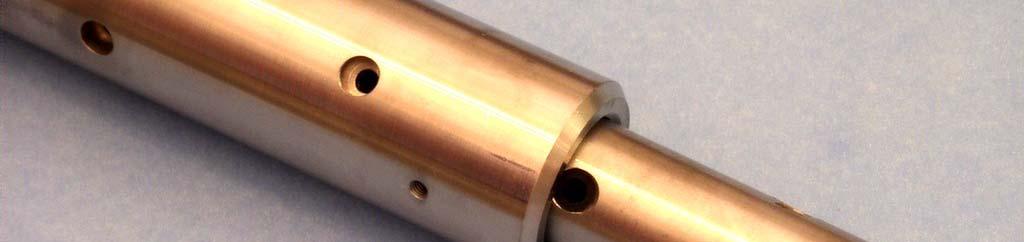
2 Gauge Sections
3 Gauge Sections Sensor Section (M006) Bull Nose (C010) OWR Section (Gauge S/N) Attaches to Shock Mitigater Data Readout Section (C011) Battery Section (B006)
4 Gauge Sections - Shock Mitigater - Used to reduce the vibration when the gun fires. Attaches to the gun or gauge carrier. - Sensor Section - Contains the two pressure ports. Attaches to the Shock Mitigater. - OWR Section - Contains the OWR Electronics. - NOTE: NEVER OPEN THIS SECTION! There are NO User Serviceable Parts inside.
5 Gauge Sections - Battery Section - Contains the Battery Fixture and Battery Pack. NEVER unscrew this section until AFTER the data is downloaded! - Data Readout Section - Unscrew THIS SECTION to download the Gauge Data. - Bull Nose Section - You can remove this and attach another gauge at this point.
6 Gauge Grease
7 Grease Uses - O-Rings - Pressure Port - Sensor Section - Gauge Section Threads - Battery Section and OWR Section - Large Stub Acme Threads - Bull Nose and Sensor Section - IES Shock Mitigater
8 Types of Grease Blue Glacier FM Grease Pressure Ports O-Rings inside the Battery Section and OWR Section Shaft of the Shock Mitigater NON-METAL anti-seize grease (black color) Threads inside the Battery Section and OWR Section (next to the O-Rings) COPPER Anti-seize grease (dark copper color) Large Stub Acme Threads on the Bull Nose, Sensor Section, and Shock Mitigater


9 Blue Glacier FM Grease Designed for high pressure, high temperature applications. Sticky characteristic resists washing out Resists gumming Synthetic (food grade) grease


10 Gauge Section O-Ring Grease Blue Glacier FM grease Battery Section and OWR Section ONLY use Blue Glacier FM grease, for ALL O-Rings located inside the gauge sections (Battery Section and OWR Section).


11 Gauge Section O-Ring Grease Blue Glacier FM grease OWR Section ONLY use Blue Glacier FM grease, for O-Rings located inside the OWR section.


12 Pressure Port Grease Sensor Section For the pressure ports, ONLY use Blue Glacier FM grease.


13 Shock Mitigater Grease IMPORTANT: ONLY use Blue FM Glacier grease on the shaft of the Shock Mitigater assembly.
 ) on the threads of the Battery Section and")
.")

14 Internal Thread Grease Battery Section and OWR Section Use ONLY the NON-METAL anti-seize i grease (black k color) ) on the threads of the Battery Section and OWR Section (located next to the high pressure O-ring seals inside the gauge sections). NOTE: DO NOT use COPPER anti-seize grease on the threads located next to the high pressure O-ring seals (inside the gauge g sections). Note: Copper Anti-Seize grease contains small metal shavings that can scratch the O-Ring surface.

 for the Large")


15 Large Stub Acme Thread Grease Shock Mitigatert Bull Nose Sensor Section Use the COPPER Anti-seize grease (dark copper color) for the Large stub acme threads. These threads are located on the Bull Nose, the Shock Mitigater, and the Sensor Section. Be sure to put grease on the small O-rings located next to the threads. NOTE: DO NOT use this grease on the Gauge Section threads located next to the high pressure O-ring seals (inside the gauge sections).
16 Gauge O-Rings Sizes and Materials
17 Select the Correct O-Ring Material for your Application There are two recommend O-rings materials used with the gauge, VITON and AFLAS. Use VITON O-Rings for Formate Fluids < 8 ph Use AFLAS O-Rings for Formate Fluids >8pH ph, if the gauge will be downhole for more then 24 hours Use PEEK Backup Rings for ALL applications. Be SURE to let us know what type of O-Ring material you need for your application.


.")

18 Gauge Section O-Rings Sizes The Large diameter O Rings used in the OWR Section and The Large diameter O-Rings used in the OWR Section and Battery Section are #2-125, 75A (Viton or Aflas). One PEEK backup ring is used for each large O-Ring.

")

19 Gauge Section O-Rings Sizes The Small diameter O Rings used in the OWR Section The Small diameter O-Rings used in the OWR Section (internal) are #2-018, 75A (Viton or Aflas). Two PEEK backup rings are used for each small O-Ring.


20 Gauge and Shock Mitigater (Stub Acme Thread) O-Rings Sizes The O-Rings used next to the LARGE STUB ACHE THREADS on the Bull Nose Section, Sensor Section, and the Shock Mitigater, are #5-964, 90A (Viton or Aflas). Four O-Rings are used for each section, two per O-Ring groove. NOTE: No backup rings are used.
21 Gauge O-Ring Removal and Installation Procedures


22 O-Ring Removal To remove the O-Ring, use a wooden dowel or pinch the O- Ring between your fingers, to get under the O-Ring. Clean off the old grease with a lint-free cloth or paper p towel. You MAY need to use a solvent to remove dirty grease.


23 O-Ring Removal NO!!! NO!!! DO NOT use a metal instrument to remove the O Ring It DO NOT use a metal instrument to remove the O-Ring. It could scratch the metal surface, causing a seal failure and possible high pressure leak, damaging the Gauge.


24 O-Ring Installation When installing O-Rings, ALWAYS use a plastic O-Ring sleeve or plastic wrap over the threads, to protect the new O-Rings from nicks, scratches and dirt, during installation.


25 O-Ring Installation 1. Slide the O-Rings and PEEK backup rings over the plastic wrap. This protects the O-Ring surface from nicks and scratches. 2. NOTE: Install the O-Ring and backup ring pair, closest to the threads, FIRST.


26 O-Ring Installation NOTE: One side of the large PEEK backup ring has a concave groove. This surface MUST face the O-Ring.
27 O-Ring Installation For the Large O-Rings in the Battery Section and the OWR Section, use only ONE PEEK backup ring with every O-Ring.
28 O-Ring Installation The PEEK Backup Ring goes on the Threaded side The O-Ring goes on the High Pressure side IMPORTANT NOTE: The PEEK backup ring MUST be positioned on the Threaded side, and the O-Ring MUST be positioned on the High Pressure side.
29 O-Ring Grease Use NON-METAL anti-seize grease (black color) on the threads. ALWAYS grease the O-Rings, inside surface, and threads BEFORE assembling the gauge sections. Use Blue FM Glacier grease on the O- Rings.
30 Gauge Assembly
31 Gauge Assembly - BE SURE the Gauge Threads and Grease are completely CLEAN! If there is ANY foreign debris or material on the threads when you assemble the gauge together, the threads will be DAMAGED! If the threads before dirty, you will need to clean them completely with a solvent. - Position the gauge sections in the vertical position, when you assemble the gauge section. This will help prevent CROSS THREADING from occurring. - Assemble the gauge sections together by hand, ONLY! This will allow you to feel is there is something wrong with the threads. IF YOU FEEL any resistance or grinding, immediately unscrew the sections and check the threads with your bare fingers for any rough surfaces. If found, you will need to have the threads repaired. The gauge is stainless steel and the threads can be easily damaged, if care is not taken.
32 Gauge Assembly - NEVER, EVER use a wrench to tighten the sections!!! Doing so will stretch the stainless steel threads, possibly damaging them! The O- RINGS in each gauge section, will keep the gauge from coming apart. - Hand tighten the Data Readout Section to the Battery Section - Hand tighten the Battery Section to the OWR Section - Hand tighten the OWR Section to the Sensor Section - Use the ½ Wrenches supplied to loosen the gauge sections. - Use the ½ Wrenches supplied to ONLY tighten: - The Bull Nose to the Data Readout Section - The Sensor Section to the Shock Mitigater - The Shock Mitigater to the GUN or GAUGE CARRIER - NOTE: If you over tighten the gauge threads, you may damage them.


33 Gauge Assembly Screw the gauge sections together, in the vertical position, and by hand ONLY! NEVER use a wrench to NEVER use a wrench to tighten the gauge sections together!


34 Gauge Assembly NOTE: ONLY use the ½ Wrenches supplied, to LOOSEN the gauge sections.


35 Gauge Assembly Shock Mitigater Bull Nose Sensor Section Use the ½ Wrenches supplied, to ONLY tighten Large Stub Acme Threads of the Bull Nose, Sensor Section, and Shock Mitigater
36 Thread Protection


37 Thread Protection ALWAYS use the Thread protectors and Red end caps to help prevent the threads and O-Rings from getting dirty. It will also protect the threads from physical damage.


38 Thread Protection ALWAYS put Thread Protectors on the threads to keep the threads and O-Rings clean, and to protect the threads from damage!


39 Thread Protection Be sure the threads and O-Rings are completely free of ANY debris. The stainless steel sections can easily be damaged if the O-Rings or threads are dirty.
40 Gauge Thread Repair
41 Thread Repair Male Threads Clean the grease off the threads with a solvent. Inspect the threads for nicks, using your bare fingers to feel for any burrs. Use a small, fine file to remove any burrs found. Female Threads If a female thread has been damaged, use a BOTTOM Tap to rechase the threads. Specify a Bottom TAP for 17-4 PH SS.
42 Thread Repair Taps for reworking gauge g threads. TAPCO USA, Inc Pike Road Loves Park Rockford, ILLINOIS (815) Specify TAP for 17-4 PH SS STUB ACME-2G, Bottom TAP (For All Gauges) PITCH DIA. MAX MIN STUB ACME-2G, Bottom TAP (For 1-11/16 Gauge) PITCH DIA. MAX MIN
43 Shipping the Gauge Back to IES for Repair
")
44 Shipping the Gauge for Repairs You can use a 3 inch dia, schedule 80, PVC pipe to ship the OWR SECTION back to IES for repair Ship ONLY the OWR SECTION (with black thread protectors installed on BOTH ends)
45 WARNINGS!
46 ALWAYS Store the Gauge Completely Assembled NEVER store a Battery Pack inside the gauge if it is not being used for a job. Store the gauge completely assembled, to keep dirt and moisture out, and to protect the gauge threads and O-Rings.
47 NEVER DISASSEMBLE THE OWR SECTION! NEVER disassemble the internal parts of the OWR SECTION. There are NO User Serviceable Parts inside the OWR SECTION (the section with the Gauge S/N scribed on it). If you disassemble the OWR SECTION The material used for packing the electronics will spill out, and you will NOT be able to repack it properly. If this material gets on the gauge threads, it could seriously damage them!


48 NEVER DISASSEMBLE THE OWR SECTION! NEVER unscrew this part on the OWR SECTION


49 NEVER DISASSEMBLE THE OWR SECTION! NEVER remove e these screws s on the OWR SECTION
50 Gauge Maintenance Procedures after EVERY Job
51 Gauge Maintenance Procedures After EVERY Job after EVERY Job! 1. Be sure you have downloaded and saved the gauge data in TWO locations, and verified the gauge data is OK BEFORE you DISCONNECT the Battery Fixture or install the RED KILL SWITCH! If you do, you will LOSE ALL YOUR DATA! 2. ALWAYS remove the OLD batteries. Never stored the gauge with old batteries inside because they might leak and damage the gauge. g 3. Pump NEW grease (Blue FM Glacier grease) through the pressure ports with the grease gun, until it is clear blue. This will clean out the small micro screen holes. Then, inspect the screens for damage, by unscrewing the hollow lock nuts, and pumping the screens out with the grease gun. 4. Remove and replace ALL the O-Rings (Viton or Aflas) in the Battery Section and OWR Section. Inspect the PEEK backup rings and replace as needed.
52 Gauge Maintenance Procedures After EVERY Job after EVERY Job! 5. Remove and Replace the Large (#2-125) and Small (#2-018) INTERNAL O-Rings located in the OWR Section (between the OWR Section and SENSOR Section). FIRST, Pump NEW grease (Blue Glacier FM grease) into the pressure ports until it is clean (BEFORE you disassemble the OWR Section and Sensor Section). This prevents contaminated grease from being pulled inside the Sensor Section when you unscrew the two sections. Unscrew the OWR and SENSOR sections, replace the internal O- Rings, and inspect and replace the small PEEK backup rings as needed. Pump NEW grease into the Sensor Section and re-assemble the Sensor and OWR Sections. NOTE: There are TWO PEEK backup rings for each small internal O-Ring. They go on BOTH sides of the small Viton O-Rings. BE SURE to clean out the old grease inside the pressure sensor hole, and put fresh grease inside it.
53 Gauge Maintenance Procedures After EVERY Job after EVERY Job! 6. IMMEDIATELY, after the job, disassemble, Inspect, and Re- Grease the Shock Mitigater. Replace the Viton tubing AND the Bolts, if the rubber is deformed, hard, or brittle. (9/16 OD x 5/16 ID Viton Tubing, 75A) If any bolts break or bend, replace ALL the bolts. Clean and Re-grease the Shock Mitigater shaft and cylinder with Blue Glacier FM grease. Do this immediately after the job to prevent the shoulder bolts or Shock Mitigater from rusting.
54 Breaking the Gauge Sections AFTER a Job


55 Breaking the Gauge Sections AFTER a Job ONLY use the supplied ½ HEX Wrenches to break the gauge sections. DO NOT use a PIPE WRENCH! Scarring the s rface co ld damage the High Scarring the surface could damage the High Pressure Rating of the gauge.
56 Remove the USED Battery Pack after EVERY Job
57 Before Removing the Battery after a JOB 1. Be sure the Gauge data is saved in TWO locations. 2. Have someone verify the data is ok. 3. THEN, you can disconnect the Battery Pack and properly discard the battery, to prevent leakage from damaging the Gauge. NOTE: NEVER store a Gauge in LONG TERM Storage with a Battery Pack in it!
58 Battery Warnings! The Gauge uses Volatile Data Memory, so if you remove the battery power from the Gauge the Gauge Data will be ERASED and permanently LOST! If you discount the Battery Fixture from the Gauge (OWR Section) the Gauge Data will be ERASED and permanently LOST! If you install the RED KILL SWITCH in the Battery Fixture the Gauge Data will be ERASED and permanently LOST!
59 Battery Fixture Warning! Sensor Section OWR Section Bull Nose Data Readout Section NEVER break the gauge between the OWR and BATTERY Sections. You will lose ALL your data!!! Battery Section ALWAYS break the Gauge at the Data ALWAYS break the Gauge at the Data Readout Section, to download the data!
60 Pressure Port Maintenance after EVERY Job
61 Cleaning the Pressure Ports and Micro Screens after EVERY Job FIRST, always Pump NEW Grease through the Pressure Ports after EVERY Job. Leave the Micro Screens installed. Using a Grease Gun connected to the 1/8 port, pump Blue Glacier FM grease into the Sensor Section until clean, blue grease comes out of both pressure ports. This cleans out the 4000 micro holes in the Micro Screens.
62 Cleaning the Pressure Ports and Micro Screens Use 1/8 Nipple 3 Using the Grease Gun pump Blue Glacier FM grease Using the Grease Gun, pump Blue Glacier FM grease into the Gauge Sensor Section until clear, blue grease comes out of both pressure ports.
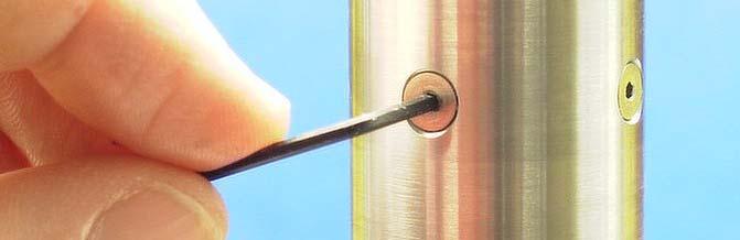
63 Removing and Inspect the Pressure Port Micro Screens Remove and Inspect both Micro Screens Unscrew BOTH Hollow lock nuts holding the micro screens Use the grease gun to pump out both screens Inspect the micro screens for any cracks or visible holes Put the micro screen back first, followed by the two washers, then the hollow lock nut Hand tighten the hollow lock nut Re-insert the 1/8 plug, hand tight


64 Removing the Pressure Port Micro Screens After cleaning the screens, unscrew the hollow lock nuts holding the screens in place. Use the grease gun to pump out the screens for inspection. DO NOT insert anything inside the holes to try to pry DO NOT insert anything inside the holes to try to pry the screens out!! They will be damaged!!


65 Inspecting the Pressure Port Micro Screens Two Pressure Ports/Screens Micro Screen NOTE: Be sure the micro screen, and 2 washers are re-installed in the order shown. Debris Screens protect the internal pressure sensor, and must ALWAYS be used. Inspect and clean them after EVERY job.
66 Replace ALL the Gauge O-Rings after EVERY Job
67 Replace ALL the Gauge O-Rings after EVERY Job Replace ALL the Internal and External Gauge O-Rings after EVERY job External O-Rings (#2-125): Battery Section and OWR Section Internal O-Rings (#2-125 and #2-018): Between Sensor Section and OWR Section Large Stub Acme Thread O-Rings (#5-964): Bull Nose, Sensor Section, and Shock Mitigater Inspect the PEEK Backup Rings and replace as needed
68 Replacing the O-Rings on the Large Stub Acme Threads
: Bull Nose,")

69 Large Stub Acme Thread O-Rings Replace the Large Stub Acme Thread O-Rings (#5-964): Bull Nose, Sensor Section, and Shock Mitigater, AS NEEDED, if they become nicked or torn. Use four O-rings, two per groove.
70 Replacing the External Section O-Rings after EVERY Job (Battery Section and OWR Section)


 on")


71 External Section O-Rings OWR Section (Connector Side) Replace the Large O-Rings (#2-125) on the Battery Section and the OWR Section, after EVERY Job. Battery Section
72 Replacing the Internal Section O-Rings after EVERY Job (Between the OWR and SENSOR Sections)
73 Replacing the Internal O-Rings 1. FIRST, Clean out the dirty grease inside the pressure sensor ports by connecting a grease gun/nipple to the 1/8 port, and pump new Blue FM Glacier Grease into it until clear, blue grease comes out of both ports. 2. Unscrew the Sensor Section and the OWR Section. 3. Remove and replace ALL the Large and Small internal O-Rings (Viton or Aflas), between the OWR and SENSOR Sections. NOTE: The O- Rings MUST be replaced after EVERY Job! Inspect the internal PEEK backup rings and replaced as needed. Re-grease the O-Rings.
74 Replacing the Internal O-Rings 4. Clean the internal pressure sensor cavity if the grease is dirty, using a Cotton Tip. DO NOT insert anything sharp or hard into the pressure sensor cavity. Put new Blue FM Glacier Grease inside it, with your finger, filling it up to the top. 5. Fill the inner cavity of the SENSOR SECTION with Blue FM Glacier Grease by pumping grease into it with the grease gun. Fill the FIRST SMALL CAVITY ONLY (see picture)! If you put too much grease inside the SENSOR SECTION, you will not be able to screw the Sensor Section and OWR Sections back together completely, because it will cause a grease lock. If this happens, you will need to remove the extra grease inside the cavity.
75 Replacing the Internal O-Rings 6. Screw the sections together BY HAND, ONLY! NOTE: NEVER USE A WRENCH TO TIGHTEN THESE GAUGE SECTIONS together! The Sensor and OWR Sections must meet together with NO GAP. If there is a GAP, then you will need to remove the excess grease inside the cavity, and STEP #5 will need to be repeated. Grease will come out the pressure ports as you screw the two sections together.


76 Clean the Pressure Ports and Micro Screens FIRST Use 1/8 Nipple 3 Pump Blue Glacier FM grease into the Gauge Sensor Pump Blue Glacier FM grease into the Gauge Sensor Section until clear, blue grease comes out of both pressure ports.
77 Replacing the Internal O-Rings Sensor Section Replace ALL the internal Replace ALL the internal O-Rings after EVERY job OWR Section
78 Install New Small Internal O-Rings O-Ring #2-018, 75A (Viton or Aflas) Install new O-Rings and place a PEEK backup ring on EACH side of the O-Ring


79 Check Peek Backup Ring Placement BE SURE the PEEK backup ring groove is in the correct position


80 Put New Grease in Sensor Port Clean out the old grease inside the pressure sensor port with a Cotton Tip Swab. Put new grease inside the pressure sensor hole, and on the O-Rings
81 Install New Large Internal O-Rings and Peek Backup Rings For the Large O-Rings in the OWR Section, use only ONE PEEK backup ring with every O-Ring. O-Ring #2-125, 75A (Viton or Aflas)


82 Be sure the Peek Backup Ring is in the Right Position The PEEK Backup Ring goes on the Threaded side The O-Ring goes on the High Pressure side IMPORTANT NOTE: The PEEK backup ring MUST be positioned on the Threaded side, and the O-Ring MUST be positioned on the High Pressure side. One Backup per O-Ring.


83 Grease the O-Rings ALWAYS grease the O-Rings, inside surface, and threads BEFORE assembling the gauge sections.


84 Fill Sensor Cavity with Grease Be sure the micro screens, hollow lock nuts, and the 1/8 grease gun fitting are installed. DO NOT OVERFILL!! VERY IMPORTANT!! Pump grease into the grease fitting, until the first deepest internal cavity is filled to the first ridge. Use a flashlight to see.


85 Grease Sensor Port and O-Rings Be sure the grease is inside the pressure sensor hole, and on the O-Rings


86 Assemble OWR and Sensor Sections Together NOTE: Screw the Gauge sections together by hand, ONLY. This way you can feel if there are any yproblems with the threads. Start the sections in the Vertical position.


87 Assemble OWR and Sensor Sections Together Leave the grease gun fitting installed while screwing the sections together As the sections are screwed together, the grease will squeeze out through both pressure ports
88 BE SURE Both Sections are Completely Assembled NO! YES! There should be NO GAP between the two gauge Sections, after they are screwed together!!
89 Gauge Assembly and Maintenance by Scott A. Ager
IES Fast Speed Gauges. 2/11/2016 Copyright (c) 2015 IES Global, Inc. All rights reserved.
 2015 IES Global, Inc. All rights reserved.") IES Fast Speed Gauges SCOTT A. AGER SCOTT@IESGLOBALINC.COM 2/11/2016 Copyright (c) 2015 IES Global, Inc. All rights reserved. IES, Inc. Company Location Navarre, Florida Contact Information Contact Scott
IES Fast Speed Gauges SCOTT A. AGER SCOTT@IESGLOBALINC.COM 2/11/2016 Copyright (c) 2015 IES Global, Inc. All rights reserved. IES, Inc. Company Location Navarre, Florida Contact Information Contact Scott
INSTALLATION INSTRUCTIONS REPAIR SEAL KIT PowerSurvivor 40E
 INSTALLATION INSTRUCTIONS REPAIR SEAL KIT PowerSurvivor 40E PURPOSE OF THE KIT The Repair Seal Kit should be installed after 1000 hours of operation. It should be installed regardless of whether or not
ADDRESSABLE DISCONNECT TOOL MODEL DE MANUAL
 Pg. 1 of 77 ADDRESSABLE DISCONNECT TOOL MODEL DE MANUAL REVISION HISTORY AUTHOR REVISED SECTION/PARAGRAPH REV RELEASED Gary Floyd Final Draft 0 03/31/17 Draft and Archived/Obsolete revisions are not to
Rugby Manufacturing Hoist Cylinder Bulletin. Preface Technical Service Bulletin
 Preface Technical Service Bulletin This bulletin applies to the following hoist models: LR-310 LR-3510 LR-3510A LR-416 LR-416B LR-165 LR-165A LR-25 LR-25A LR-525 LR-26B LR-26C LR-27B LR-623 LR-28A LR-2066
D-15/G-15 Maintenance
 D-15/G-15 Maintenance NOTE: The numbers in parentheses are the Reference Numbers on the exploded view illustrations found later in this manual and in the Parts Manual. Daily Check the oil level and the
servicing the swivel
 servicing the swivel The swivel seals and bearings require periodic replacement. This document describes how to determine which service procedure to use to service the swivel assembly, part number 101110.
SM64052 Maintenance & Repair Manual Commercial 2" Unisex Coupling - Valved Model 64052
 Aerospace Group Conveyance Systems Division Carter Brand Ground Fueling Equipment SM64052 July 2004 Applicable additional manuals: SM64051 Commercial 2" Unisex Coupling, Non-Valved Maintenance & Repair
VIS Standard and Wheel Motors 45 Series Parts and Repair Information -005
 VIS Standard and Wheel Motors Parts and Repair Information -005 VIS Standard & Wheel Motors - Table of Contents Table of Contents Exploded View...2 Parts List for Standard and Wheel Motor...3 Disassembly,
Sport Model with an easy-lube spindle
 1. List of tools: Back To Top 1. Safety glasses 2. Hammer 3. Brass or aluminum punch 4. channel locks 5. Block of wood or plastic 6. grease gun 7. razor knife 8. 6" long, 2" diameter or 1 ½" diameter pipe
Char-Lynn Hydraulic Motor. Repair Information Series. April, 1997
 Char-Lynn Hydraulic Motor April, 1997 Repair Information Geroler Motors 002 00 004 Parts Drawing 1 See Note 2 Page 1 22 1 9 1-1/4 Split Flange Ports 8 7 6 5 B 1 See Note 2 Page 2 24 4 14 19 20 15 1 18
Firehawk Second Stage Regulator Fire Service
 Firehawk Second Stage Regulator Fire Service MAINTENANCE AND REPAIR TAL 1701 (L) Rev. 2 MSA 2017 Prnt. Spec. 10000005389(I) Mat. 10147454 Doc. 10147454 TAL 1701 (L) Rev. 2-10147454 2 NON-CBRN FIREHAWK
Maintenance Information
 16573370 Edition 2 February 2014 Air Grinder 99V Series Maintenance Information Save These Instructions Product Safety Information WARNING Failure to observe the following warnings, and to avoid these
HFB Steering Gear Service Manual
 TRW Automotive Commercial Steering Systems HFB Steering Gear Service Manual HFB64 SERIES Die Cut HFB64 Integral Hydraulic Power Steering Gear This steering gear was specifically designed for motor trucks;
POWER STEERING PUMP REBUILDING SPK101 Read instructions completely before removal & disassembly
 POWER STEERING PUMP REBUILDING SPK101 Read instructions completely before removal & disassembly DISASSEMBLY: 1. Remove pump from car and allow to drain. 2. Remove pulley from front of pump. This requires
I-232.T3S2 Victaulic Style 232 Restrained, Flexible High-Pressure Coupling
 WARNING Read and understand all instructions before attempting to install any Victaulic piping products. Depressurize and drain the piping system before attempting to install, remove, or adjust any Victaulic
E31 Repair Procedure Replace Front Wheel Hub/Bearing Assembly
 E31 Repair Procedure 31-21 Replace Front Wheel Hub/Bearing Assembly Disclaimer This repair procedure is provided as is and is not authoritative with respect to any BMW repair operation. Mark F. Fling is
PRESSURE RELIEF VALVE: DISASSEMBLY, INSPECTION, and ASSEMBLY CONTENTS
 Page 1 of 35 PRESSURE RELIEF VALVE: DISASSEMBLY, INSPECTION, and ASSEMBLY CONTENTS 1. Overview 2. Disassembly of Valves with Liner Subs and press-in Bushing (Models 30525 and 30550). 2.1. Routine Disassembly
ARMAGEDDON tm BY AIR AMERICA, INC.
 ARMAGEDDON tm BY AIR AMERICA, INC. Congratulations! You have purchased the most advanced high-pressure Air/Nitrogen Paintball system available to the Paintball World. Your Air America ARMAGEDDON tm is
LJ20 Distributor - Disassembly Inspection Repair
 LJ20 Distributor - Disassembly Inspection Repair Old Codger New To Old Suzuki Jeeps The odometer on this 1972 LJ20 indicated the distributor had less than 10,000 miles of wear but during that time it had
CP-1, CP-2, CP-2L & CPD-2 Series Overhaul
 Replacement of Mechanical Seals for CM, CMU, CS and CSU Series Pumps Installation Instructions Form No. F-1031 Section 5013 Issue Date 03/01/85 Rev. Date 02/08/11 CP-1, CP-2, CP-2L & CPD-2 Series Overhaul
I-231.T2S1/CLAD. Victaulic Style 231 Non-Restrained, Flexible Expansion Coupling with Cladding on Expansion Side of Pipe WARNING IMPORTANT INFORMATION
 WARNING Read and understand all instructions before attempting to install any Victaulic piping products. Depressurize and drain the piping system before attempting to install, remove, or adjust any Victaulic
HIGH PRESSURE CONTROL VALVE PISTON BALANCED
 PISTON BALANCED All Rights Reserved. All contents of this publication including illustrations are believed to be reliable. And while efforts have been made to ensure their accuracy, they are not to be
Installation Instructions
 Preparing your vehicle to install your brake system upgrade 1. Rack the vehicle. 2. If you don t have a rack, then you must take extra safety precautions. 3. Choose a firmly packed and level ground to
F-20/G-20 Maintenance
 F-20/G-20 Maintenance NOTE: The numbers in parentheses are the Ref. Nos. on the illustrations in the Parts Manual. Periodically Change the oil after the first 100 hours of operation, and every 1000 operating
Truckmount Repairs Cat 290 Pump Repair
 Cat 290 Pump Repair COMMON STOCKED PARTS 3 PST101802 Cylinder CAT 290 3 PST26112 Cylinder CAT 280 1 PHY027-004 Oil Filler Cap Black (old 280 & 290 s) 1 PST43211 Oil Filler Cap - Red 1 PST14177 O-ring Oil
Maintenance Information
 16572679 Edition 2 May 2014 Air Drill QP Series Maintenance Information Save These Instructions Product Safety Information WARNING Failure to observe the following warnings, and to avoid these potentially
INSTRUCTIONS FOR REPLACING THE SEALS, SHAFT SUPPORT BUSHING AND SHAFT SUPPORT BEARING IN A MODEL PBF-50, 50S, & 100 PROPELLER WASHED BEAD FILTER
 May 28, 2008 INSTRUCTIONS FOR REPLACING THE SEALS, SHAFT SUPPORT BUSHING AND SHAFT SUPPORT BEARING IN A MODEL PBF-50, 50S, & 100 PROPELLER WASHED BEAD FILTER Parts for 7/8 Seal Replacement Kit (PBF-SK7/8)
SERVICE MANUAL L130B / L4130 Series Logstacker Drive Axle With Bolt-On Stub End Retainer
 SERVICE MANUAL L130B / L4130 Series Logstacker Drive Axle With Bolt-On Stub End Retainer Page 1 Allied Form #80-930 Rev 07/2009 SERVICE MANUAL LOG STACKER DA202 DRIVE AXLE TABLE OF CONTENTS PROCEDURE FOR
Lakela nd H2 Low Speed Stator Coil Installation
 Lakela nd H2 Low Speed Stator Coil Installation Step 1: Place the stator assembly on a padded surface to protect the plastic signal generators, and orient it as shown in figure 1. The low speed coil is
6200 Series. Specifications. Fluid End Power End Models 6211, 6212, 6221, & 6222 Models 6241 & 6242 Part Material Part Material Part Material
 5.2018.12.i 6200 Series Specifications The Flomore 6200 Series Pump line consists of a series of basic pump options all developed from a modular power unit. All units are pneumatically driven positive
KHR Series Regulators
 KHR Series Regulators Maintenance Instructions Kit Contents retainer Poppet Poppet spring Poppet damper Outer body seal Inner body seal Upper piston seal seal backup ring Main piston seal vent seal Self-vent
SERVICE INSTRUCTIONS FOR SEAL REPLACEMENT OF POWER GEAR HYDRAULIC LEVELING LEGS
 SERVICE INSTRUCTIONS FOR SEAL REPLACEMENT OF POWER GEAR HYDRAULIC LEVELING LEGS 82-L0352 REV 8 4-27-2011 WARNING! HYDRAULIC COMPONENTS CAN CAUSE SERIOUS INJURY OR DEATH IF PROPER SAFETY PRECAUTIONS ARE
FRONT AXLE SECTION FAX CONTENTS TRANSMISSION & DRIVELINE FAX-1 PRECAUTION... 2 REMOVAL AND INSTALLATION... 6 PREPARATION... 3
 TRANSMISSION & DRIVELINE SECTION FAX A FRONT AXLE B C FAX CONTENTS E PRECAUTION... 2 PRECAUTIONS... 2 Precaution...2 PREPARATION... 3 PREPARATION... 3 Special Service Tool...3 Commercial Service Tool...3
Steering Gearbox Disassembly
 Steering Gearbox Disassembly Steering Rack Disassembly 5. Unbend the lock washer. Before disassembling the gearbox, wash it off with solvent and a brush. Do not dip seals and O-rings in solvent. 1. Remove
Maintenance. Daily. Shutdown Procedure. Periodically. During Freezing Temperatures
 Maintenance Daily Check the oil level and the condition of the oil. When the pump is operating, the oil in the pump housing gets warm and expands, filling into the oil reservoir. Depending on the type
RUGBY HOIST CYLINDERS SERVICE BULLETIN
 TRUCK BODIES & EQUIPMENT INTERNATIONAL, Inc. Website: www.rugbymfg.com E-mail: sales@rugbymfg.com Phone: (701) 776-5722 Toll Free: (800) 869-9162 RUGBY HOIST CYLINDERS SERVICE BULLETIN This bulletin applies
Tube Fitting Installation Instruction
 Tube Fitting Installation Instruction TABLE OF CONTENTS I. Tubing Preparation 1. Tube pg 2-3 II. Tube Fitting Installation Instruction 1. Hy-Lok Tube Fitting Installation 2. Gap Inspection 3. Re-Assembly
I-317. AWWA Check Valves WARNING INSTALLATION AND MAINTENANCE INSTRUCTIONS SERIES 317 WARNING
 Read and understand all instructions before attempting to install, remove, adjust, or perform maintenance on any Victaulic piping products Wear safety glasses, hardhat, and foot protection. Failure to
Gelcoat Fluid Section
 3102-00-01 Fluid Section MAGNUM VENUS PRODUCTS Maintenance & Repair Manual Part No. M3102-00-01 Revision 05.30.01 Maintenance & Repair Manual Fluid Section Module MVP Venus Phone: (253) 854-2660 (800)
H Low Torque Impact Wrench
 SERVICE MANUAL H8508-3 Low Torque Impact Wrench Serial Code AKW Read and understand all of the instructions and safety information in this manual before operating or servicing this tool. Register this
D/G-03 Maintenance. Shutdown Procedure During Freezing Temperatures. Daily. Periodically
 D/G-03 Maintenance NOTE: The numbers in parentheses are the Ref. Nos. on the illustrations in the Parts Manual. Daily Check the oil level and the condition of the oil. The oil level should be 3/4 in. (20
D/G-35 Maintenance. Shutdown Procedure During Freezing Temperatures. Daily. Periodically
 D/G-35 Maintenance NOTE: The numbers in parentheses are the Reference Numbers on the exploded view illustrations found later in this manual. Daily Check the oil level and the condition of the oil. The
Drop-In Inside Blowout Preventer Valve
 Drop-In Inside Blowout Preventer Valve Disassembly and Assembly Procedures Global Manufacturing, Inc. Lafayette, Louisiana USA 70508 Ph (337) 237-1727 Fax (337) 232-9353 Disassembly and Assembly Procedures
Motion System Components Diagram. Note: #2 Mirror Cover and X-Axis Motor Cover have been removed for visibility. Maintenance.
 Professional Laser System PLS3.75, PLS4.75, PLS6.75 and PLS6.150D Keeping the laser system clean will ensure the highest quality engraving. A clean laser system is the best performing laser system. The
3M Overhaul Service Kit
 SERVICE INSTRUCTIONS FOR 3M 12,000 RPM 3 in. (77 mm) RANDOM ORBITAL SANDERS 3M Overhaul Service Kit The part number 20346, 3M Overhaul Service Kit, contains all the replacement parts that naturally wear
AIR/HYDRAULIC INJECTION GUN MODEL INSTRUCTIONS
 I. OPERATION & DESCRIPTION The Air / Hydraulic Injection Gun is a high-pressure tool that should be used with caution and according to these instructions. IMPORTANT: The Gun is 0,000 psi rated. Do not
DeZURIK " BAW AWWA BUTTERFLY VALVES WITH EPOXY-RETAINED SEAT
 DeZURIK 20 144" BAW AWWA BUTTERFLY VALVES WITH EPOXY-RETAINED SEAT Instruction D10373 April 2017 Instructions These instructions provide information about the 20 (250 F2 model only) and the 24-144 BAW
Technical Manual MSI Hydraulic Adjustable Choke
 Technical Manual MSI Hydraulic Adjustable Choke MSI A Division of Dixie Iron Works, Ltd. 300 W. Main St. Alice, TX 78332 www.diwmsi.com (800) 242-0059 Revision A TABLE OF CONTENTS SECTION 1 WARNINGS...
Power Train. Chapter 5
 Chapter Power Train Spefications................................................................. -3 Test Spefications........................................................ -3 Repair Spefications.......................................................
12. FRONT WHEEL/FRONT BRAKE/
 12 4.5kgm 0.9kg-m 4.5kg-m 12-0 SERVICE INFORMATION... 12-1 HYDRAULIC BRAKE... 12-10 TROUBLESHOOTING... 12-2 FRONT SHOCK ABSORBER... 12-16 FRONT WHEEL... 12-3 STEERING HANDLEBAR... 12-19 FRONT BRAKE...
Operation and Maintenance Instructions
 Operation and Maintenance Instructions One Research Drive Stratford, CT 06615 (203) 375-0063 www.sonicmixing.com 1 Installation and Start-up Do not perform following adjustments without disconnecting power
CYLINDER REBUILD PROCEDURE - SUSPENSION, REAR
 CYLINDER REBUILD PROCEDURE - SUSPENSION, REAR 220102 This cylinder is precharged with nitrogen. All dry nitrogen (N 2 ) pressure MUST be relieved before cylinder is removed from the vehicle. This cylinder
Second Stage Regulator - 1/4 Turn
 Second Stage Regulator - 1/4 Turn MAINTENANCE AND REPAIR TAL 806 (L) Rev. 6 MSA 2008 Prnt. Spec. 10000005389 (I) Mat. 10042827 Doc. 10000015245 1/4 TURN SECOND STAGE REGULATOR SECOND STAGE REGULATOR COMPONENTS
I-234. Victaulic Styles 234/234S Restrained, Flexible Single-Gasket Couplings WARNING IMPORTANT INFORMATION ITEMS PROVIDED WITH SHIPMENT:
 WARNING Read and understand all instructions before attempting to install any Victaulic piping products. Depressurize and drain the piping system before attempting to install, remove, or adjust any Victaulic
D/G-10 Maintenance. Daily. Shutdown Procedure During Freezing Temperatures. Periodically
 D/G-10 Maintenance NOTE: The numbers in parentheses are the Reference Numbers on the exploded view illustrations found in this manual and in the Parts Manual. Daily Check oil level and condition of oil.
Maintenance Information
 04581245 Edition 2 May 2014 Air Grinder, Die Grinder and Sander Series G2 (Angle) Maintenance Information Save These Instructions Product Safety Information WARNING Failure to observe the following warnings,
(8) Perform negative-pressure check IAW paragraph (9) Install mask-mounted regulator in regulator holder.
 Perform negative-pressure check IAW paragraph (9) Install mask-mounted regulator in regulator holder.") (8) Perform negative-pressure check IAW paragraph 6.6.3. (9) Install mask-mounted regulator in regulator holder. 6.7.3.2 Mask-Mounted Regulator Removal and Installation. O-ring, PN 18002-00 Pliers, slip
(8) Perform negative-pressure check IAW paragraph 6.6.3. (9) Install mask-mounted regulator in regulator holder. 6.7.3.2 Mask-Mounted Regulator Removal and Installation. O-ring, PN 18002-00 Pliers, slip
DESCRIPTION Acura TSX SUSPENSION Front - TSX. NOTE: For system description and component location, see Fig. 1.
 2004 SUSPENSION Front - TSX DESCRIPTION NOTE: For system description and component location, see Fig. 1. Fig. 1: Identifying Front Suspension Components Wednesday, March 12, 2008 8:30:45 8:30:55 PM Page
Material Specifications
 5.2012.12.b 6200 Series Specifications The Flomore 6200 Series Pump line consists of a series of basic pump options all developed from a modular power unit. All units are pneumatically driven positive
FLOWSERVE CORPORATION NOBLE ALLOY VALVE BALL VALVE REPAIR INSTRUCTION
 FLOWSERVE CORPORATION NOBLE ALLOY VALVE BALL VALVE REPAIR INSTRUCTION Cookeville Valve Operation 1978 Foreman Drive Cookeville, TN 38541 PH: 800-251-6761 931-432-4021 FAX: 931-432-5518 CONTENTS FLOWSERVE/NOBLE
Suzuki GS1000G fork seal replacement
 Suzuki GS1000G fork seal replacement Before you start you require: 1) To read workshop service manual for your model 2) Socket allen key M8 3) Torque wrench 4) Special tool to hold inner, make your own,
Hydraulics. Part B, Section 1. This section covers the following unit configurations. 3700V 3800V 3900V
 Part B, Section 1 Model Voltage Pump Manifold Control This section covers the following unit configurations. 3500V 3700V 3800V 3900V All Piston (F) 4-Port (A) 6-Port (B or C) -Port (S or T) Vista Standard
Maintenance Information
 Form 16575334 Edition 1 April 2005 Electric Screwdrivers EL, EP and ET 34V DC Series Maintenance Information Save These Instructions WARNING Maintenance procedures have the potential for severe shock hazard
4.2 WATER PUMP (GEAR CASE MOUNTED AND LATER) (GCM)
 (GCM)") SERIES 60 SERVICE MANUAL 4.2 WATER PUMP (GEAR CASE MOUNTED - 1991 AND LATER) (GCM) The centrifugal-type water pump circulates the engine coolant through the cooling system. The pump is mounted on the rear
SERIES 60 SERVICE MANUAL 4.2 WATER PUMP (GEAR CASE MOUNTED - 1991 AND LATER) (GCM) The centrifugal-type water pump circulates the engine coolant through the cooling system. The pump is mounted on the rear
Figure High-Pressure Hose Assembly Removal.
 6.7.4.5 High-Pressure Hose Assembly Removal and Installation. Tools, Parts, and Materials. Hammer, hand, machinist s ballpeen, 8 oz. O-ring, PN 55622-00 Punch, pin, 1/8 inch Ring, backup, PN 18071-02 (1)
Installation Notes: #86000-R Race Series +3.5 L/T Kit
 159 North Maple St. Unit J, CORONA CA 92880 P. 951-737-9682 F. 951-737-9006 WWW.CHAOSFAB.COM Installation Notes: #86000-R Race Series +3.5 L/T Kit Factory manual is recommended for removal and re-installation
Maintenance Information
 16573321 Edition 3 February 2014 Air Grinder Series 61H Maintenance Information Save These Instructions Product Safety Information WARNING Failure to observe the following warnings, and to avoid these
Injector. General Information CAUTION. Use only the specified injector for the engine.
 Page 1 of 32 006-026 Injector General Information CAUTION Use only the specified injector for the engine. All engines use closed nozzle, hole-type injectors. However, the injectors can have different part
I-795/906. Series 795 and 906 Installation-Ready Knife Gate Valves WARNING INSTALLATION AND MAINTENANCE INSTRUCTIONS
 INSTALLATION AND MAINTENANCE INSTRUCTIONS I-795/906 Series 795 and 906 Installation-Ready Knife Gate Valves HANDWHEEL OPERATOR PNEUMATIC OPERATOR HYDRAULIC OPERATOR WARNING Read and understand all instructions
The M7 Direct Flow Intercooler (DFIC) Installation Guide
 Installation Guide") The M7 Direct Flow Intercooler (DFIC) Installation Guide This information is meant only as a guide. The author of this information,, or any M7 Tuning employees assumes no liabilities for any outcomes resulting
The M7 Direct Flow Intercooler (DFIC) Installation Guide This information is meant only as a guide. The author of this information,, or any M7 Tuning employees assumes no liabilities for any outcomes resulting
114 NOSE SEIKO CO.,LTD NOSE SEIKO CO.,LTD
 114 NOSE SEIKO CO.,LTD NOSE SEIKO CO.,LTD 115 and Part Code Applicable axis diameter Feature Part Code 5 ~ 3 General purpose cam follower with screwdriver groove on the stud head. Available with stainless
TECHNICAL SERVICE MANUAL HEAVY-DUTY BRACKET MOUNTED PUMPS SERIES 120 and SERIES 124 MODELS J, K, KK, L, LQ, LL AND LM
 TECHNICAL SERVICE MANUAL HEAVY-DUTY BRACKET MOUNTED PUMPS SERIES 120 and SERIES 124 MODELS J, K, KK, L, LQ, LL AND LM SECTION 3 BULLETIN TSM-120-124-V ISSUE B-2005 CONTENTS Special Information 2 Maintenance
Maintenance Information
 45528270 Edition 1 June 2007 Barring Motor T480 Series Maintenance Information Save These Instructions WARNING Always wear eye protection when operating or performing maintenance on this Barring Motor.
Engine Oil Leak at Crankshaft Rear Main Oil Seal (Replace with Revised Crankshaft Rear Main Oil
 Document ID# 1706007 2004 Cadillac CTS Engine Oil Leak at Crankshaft Rear Main Oil Seal (Replace with Revised Crankshaft Rear Main Oil Seal) #05-06-01-019A - (Sep 22, 2005) Engine Oil Leak at Crankshaft
Instruction Manual For DODGE. Airport Baggage Handling Systems Speed Reducers
 Instruction Manual For DODGE Airport Baggage Handling Systems Speed Reducers ABHS TXT109 - TXT115 - TXT125 ABHS TXT209 - TXT215 - TXT225 ABHS TXT309A - TXT315A - TXT325A ABHS TXT409A - TXT415A - TXT425A
Eaton Hydraulic Motor. Repair Information. Series VIS 45. January, 2000
 Eaton Hydraulic Motor January, 2000 Repair Information Series VIS 45 Standard and Wheel Motor 003 Parts Drawing Shuttle/Relief Valve Parts Shown Enlarged Below End Cap Geroler Balance Plate Back-up Ring
MP and MP Diaphragm and Seal Kits for MP8000 Series Actuators
 MP8000-6325 and MP8000-6350 Diaphragm and Seal Kits for MP8000 Series Actuators Contents of the MP8000-6325 Diaphragm and Seal Kit for MP82 and MP83 Actuators One seal, 5/8 in. Internal Diameter (I.D.)
Operation & Maintenance Manual 4900 Series Pipeline Injection Pumps Bulletin 150
 340 West Benson Avenue Grantsburg, WI 54840 1-800-366-1410 715-463-5177 www.northern-pump.com Table of Contents Introduction... 3 Rotation... 4 Hydraulic Balance... 5 Cautionary Statements... 6 Pump Installation...
Seal Damage Analysis and Troubleshooting
 LIGHT VEHICLE TECHTIPS LV13 Seal Damage Analysis and Troubleshooting When attempting to diagnose seal damage and seal-related issues, ask these questions and then review the troubleshooting guide on the
Maintenance Information
 51984144 Edition 6 May 2014 Air Paving Breaker MX60 & MX90 Maintenance Information Save These Instructions Product Safety Information WARNING Failure to observe the following warnings, and to avoid these
DP5 Pump. 5:1, Air-operated, Heavy Duty, Oil. General. Operation. Technical Data. Installation R1 09/10
 DP5 Pump 5:1, Air-operated, Heavy Duty, Oil General The DP5 Pump is a compressed air-operated reciprocating piston medium pressure pump. These pumps are suitable for distribution of all types of light
Model 210HP Beadbreaker
 00020HP:99900657: 2040409 Model 20HP Beadbreaker PARTS AND SERVICE MANUAL IOWA MOLD TOOLING CO., INC. BOX 89, GARNER, IA 50438-089 TEL: 64-923-37 TECHNICAL SUPPORT FAX: 64-923-2424 MANUAL PART NUMBER 99900657
INSPECTION & MAINTENANCE BULLETIN ARI 1301/1302 1" Plug Type Angle Valves
 INSPECTION & MAINTENANCE BULLETIN ARI 1301/1302 1" Plug Type Angle Valves Item # Description Item # Description 1 Body 12 Washer 2 Packing Retainer 13 Bushing 3 Packet Set 14 Bolt 4 Jam Nut 15 Yoke 5 Stud
Tooling Assistance Center
 Safeguards are designed into this application equipment to protect operators and maintenance personnel from most hazards during equipment operation. However, certain safety precautions must be taken by
4. Control Valve (Power Steering Gearbox)
") 4-3 [W4A0] SERVICE PROCEDURE A: CHECKING OIL LEAKING POINTS S4M0153A (1) Power cylinder (2) Cylinder (3) Rack piston (4) Rack axle (5) Input shaft (6) Valve housing 1. OIL LEAKING POINTS 1) If leak point
4-3 [W4A0] SERVICE PROCEDURE A: CHECKING OIL LEAKING POINTS S4M0153A (1) Power cylinder (2) Cylinder (3) Rack piston (4) Rack axle (5) Input shaft (6) Valve housing 1. OIL LEAKING POINTS 1) If leak point
Maintenance Information
 45530136 Edition 1 July 2008 Electric Screwdrivers EL 24V DC Series Maintenance Information Save These Instructions WARNING Always wear eye protection when operating or performing maintenance on this tool.
PIKE DUAL AIR PICTORIAL INSTRUCTIONS. INSTRUCTIONS FOR INSTALLING ENDURO FORK SEALS AND CHANGING SEMI-BATH OIL in RockShox PIKE Dual Air Forks
 INSTRUCTIONS FOR INSTALLING ENDURO FORK SEALS AND CHANGING SEMI-BATH OIL in RockShox PIKE Dual Air Forks RECOMMENDED PARTS AND TOOLS -Bicycle work stand -Plastic bucket/drain pan -5mm Allen wrench -DH
This chapter covers the location and servicing of the front brake components for the KYMCO MXU 700i and MXU 500i models.
 KYMCO MXU 500i/700i Repair Manual Brake System 9.Brake System This chapter covers the location and servicing of the front brake components for the KYMCO MXU 700i and MXU 500i models. 1.Brake Discs... 9-3
Eaton Hydraulic Motor. Repair Information. VIS 45 Series Two Speed Bearingless -001
 Eaton Hydraulic Motor Repair Information VIS 45 Series Two Speed Bearingless -001 VIS 45 Series Two Speed Bearingless 17 Shuttle Valve Parts Relief Valve Parts 40 30 41* 30 Relief Valve Parts Shown Enlarged
Model 800 Disassembly Instructions and Troubleshooting
 Model 800 Disassembly Instructions and Troubleshooting 1 Index Page Solenoid Disassembly Instructions 2,3 Removing Adaptor from Anti-siphon Body 4,5 Adaptor Disassembly Instructions 6-9 Troubleshooting
DRIVE SHAFT LOCATION INDEX
 DRIVE SHAFT LOCATION INDEX 2005 DRIVELINE/AXLE Drive Shaft - MX-5 Miata Fig. 1: Identifying Drive Shaft Location DRIVE SHAFT PRE-INSPECTION 1. Inspect the dust boot on the drive shaft for cracks, damage,
Installation Instructions
 Installation Instructions BW Seals RIS Seal Rubber in shear slurry seal Experience In Motion 1 Equipment Check 1.1 Follow plant safety regulations prior to equipment disassembly: lock out motor and valves.
3M Overhaul Service Kit
 SERVICE INSTRUCTIONS FOR 3M 12,000 RPM 5 in. (127 mm) and 6 in. (150 mm) RANDOM ORBITAL SANDERS 3M Overhaul Service Kit The part number 20347, 3M Overhaul Service Kit, contains all the replacement parts
2010 F-650, 750 Super Duty Workshop Manual
 11. Check the seal for heat damage (bottom view). If the seal is stiff and brittle, and not pliable like the new seal (top view), it is probably heat damaged. Determine and fix the cause of excessive heat
Circulation Kits for CP Pumps
 Instruction Sheet P/N 08000C Description This instruction sheet covers two circulation kits for CP Pumps: Stainless steel circulation kit, with Viton O-rings Stainless steel circulation kit, with EPR O-rings
Pleasereadandfulyunderstandthisprocedurepriortoperforminganybearingmaintenance.
 Pleasereadandfulyunderstandthisprocedurepriortoperforminganybearingmaintenance. Thismanualoutlinesgeneraldirectionsforbearingmaintenanceusingtestedefective techniques.additionaly,alcommonandacceptedsafetypracticesaretobefolowedin
Fishing Bumper Sub. Manual D450
 Fishing Bumper Sub Manual D450 Contents Fishing Bumper Sub Overview...2 Use...2 Construction...2 Illustration...3 Operation...4 Fishing Operations...4 Drilling Operations...4 Applying a Downward Blow...4
LEAK TEST PROCEDURE APPLICABLE TO DC3 INTELLI-GRIP LIFTERS MODELS MRT4-DC3, MRTA8-DC3, MRTALP8-DC3 AND PC/P1-DC3 SERIES
 LEAK TEST PROCEDURE APPLICABLE TO DC3 INTELLI-GRIP LIFTERS MODELS MRT4-DC3, MRTA8-DC3, MRTALP8-DC3 AND PC/P1-DC3 SERIES TESTING AND MAINTENANCE MUST BE DONE BY A QUALIFIED PERSON KEEP FOR FUTURE REFERENCE
Installation Instructions for the EVO3 Height-Adjustable Ultimate Short Shifter
 Installation Instructions for the EVO3 Height-Adjustable Ultimate Short Shifter for 1992-2005 325, 323, 318 and 1986-1994 525, 528, 535, 540 5-speed models only. (part number USSE3 and USSE5) Thank you
Service Manual. Climate Control Inc.
 SECTION 2 Service - Clutch Servicing (Removal & Installation) - Shaft Seal Servicing (Removal & Installation) - Head & Valve Plate Servicing (Removal & Installation) - Baseplate Servicing (Removal & Installation)