Speedo With Telltales and Display 85mm Tech Support Instruction Sheet # A2C Rev
|
|
|
- Meghan Wilcox
- 5 years ago
- Views:
Transcription
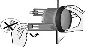
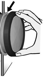
 Wiring the Gauge (Illustration A): 1.")
1 Gauge Installation: 1. Select the desired mounting location of the instrument. 2. Depending on your mounting situation it might be necessary to configure the gauge before installation. See page 2 - Setting up the Speedometer. 3. Mount the gauge and secure with the VDO Spin-Lok Clamp. (See page 5 for mounting options and instructions) Wiring the Gauge (Illustration A): 1. Route wires from the instrument to: (a) the battery (+) constant power after the fuse box or user supplied in-line fuse 5 amp fast-blow. (b) the battery (+) after the ignition switch and after the fuse box or user supplied in-line fuse 1 amp fastblow. (c) the light switch after the fuse box or user supplied inline fuse -1 amp. (d) a good, dedicated ground location. (e) Signal source - Hall Effect sender, Inductive sender, or Electronic control box. 2. Connect the harness according to the following wiring Matrix: Read these instructions thoroughly before installation. Do not deviate from assembly or wiring diagram. Always disconnect battery ground before making any electrical connections. IMPORTANT: Mounting dimensions vary for different gauges. Please be certain to follow the instructions for your specific gauge. Parts List Item Description Qty 1 85mm Gauge 1 2 Spin-Lok Clamp 1 3 Gasket pin Harness pin Harness 1 6 Push-button 1 7 Instruction Sheet 1 Pin Description 1 Red - Battery constant (+12 / 24 V) 2 Black - Ground 3 Blue/Black - Sender Signal (-) 4 Brown - Battery switched (+12 / 24 V) 5 Green - Sender Signal (+) 6 Blue/Red - Illumination (+) 7 Not Connected 8 Not Connected Note - Use 18 AWG for wire harness Merchandise warranted against defects in factory workmanship and materials for a period of 24 months after purchase. This warranty applies to the first retail purchaser and covers only those products exposed to normal use or service. Provisions of this warranty shall not apply to a VDO product used for a purpose for which it is not designed, or which has been altered in any way that would be detrimental to the performance or life of the products, or misapplication, misuse, negligence or accident. On any VDO part or VDO product found to be defective after examination by manufacturer, manufacturer will only repair or replace the merchandise through the original selling dealer. Manufacturer assumes no responsibility for diagnosis, removal and/or installation labor, loss of vehicle use, loss of time, inconvenience or any other consequential expenses. The warranties herein are in lieu of any other expressed or implied warranties, including any implied warranty or merchantability of fitness, and any other obligation on the part of manufacturer, or selling dealer. Illustration A
2 Programming the Speedometer (Illustration B): Operation Basics: Short Press (< 2sec.) - Long Press (> 2sec.) The Configuration button must be connected before programming can be done. The display will return to normal operation if a button is not pressed for 30 seconds. Any settings you have made will not be saved. Setting the Speedometer Input: 1. With the ignition switch off, hold in the Configuration button 2. Turn ignition on 3. Release the Configuration button 4. INPUT will appear on the display 5. Long press to get to the Input setting screen 6. Short press to cycle through FREQUE or NMEA. NOTE: NMEA input requires no calibration. 7. Long press to exit input setting 8. INPUT will appear on the display Calibrating the Speedometer (FREQUE Input) Autocal or Manual Autocalibration (Autocl): The auto-calibration function can be used successfully on a road with the distance of one mile accurately designated. The road does not have to be straight. 1. While in configuration mode (Refer to step 1-3 above) Short press to get to the Autocl setting screen. 2. Long Press to enter the autocal menu button will appear. 3. When you are ready to begin your calibration run, short press the button again will appear on the display. 4. Drive the reference distance of one mile (or 1 kilometer). NOTE: As you drive this distance, the pulses will be displayed and the needle will move. If the Speedo is not counting pulses, no useable impulse is being detected. 5. After 1 mile, Short press. The number of pulses counted during the calibration run will be displayed. 6. Long press to save the pulse count and exit the autocalibration ( PULSE will appear on the display). 7. Turn off ignition. The Speedometer is now programmed. Pin Manual Calibration: Description 1 Blue - NMEA0183-B (optional, GPS) 2 White - NMEA0183-A (optional, GPS) 6 Black/Red - Left Turn (+ Trigger) 7 Black/White - High Beam (+ Trigger) 9 Yellow - Park Brake (+ Trigger) 10 Orange - Right Turn (+ Trigger) 11 Green/Black Configuration (- Trigger) 12 Green/Red - Mode (+ Trigger) 13 Red - Alarm Output(max 100 ma) 3-5, 8, 14 unassigned NOTE: The Push-button supplied is to be used as a: a) Configuration button to set up the speedometer before use. b) Mode button for operation of the speedometer during normal use. Illustration B 1. With the ignition switch off, hold in the Configuration button.
3 2. Turn ignition on. 3. Release the Configuration button. 4. INPUT will appear on the display 5. Short press twice - PULSE will appear on the display 6. Long press to get to the pulse setting screen 7. Short press will increase the value of the flashing number by Long press to move to the next position. 9. Continue until right most digit is set. 10. Long press to exit pulse setting. 11. PULSE will appear on the display. 12. Turn off ignition. The Speedometer is now programmed. The Configuration button can be disconnected and connected to be used as the Mode button. Set Unit and Alarm Threshold: 1. With the ignition switch off, hold in the Mode button 2. Turn ignition on 3. Release the Mode button 4. UNIT will appear 5. Long press to enter UNIT menu 6. Short press to change the clock format 12 hour am/pm - 24 hour 7. Long press to return to UNIT menu 8. Short press to show WARN on the display 9. Long press to enter WARNING menu 10. Short press to set Speed warning limit. 11. Short press will increase the value of the flashing number by 1 - Long press will move to the next position 12. Continue until right most digit is set. 13. Long press to exit. 14. Turn off ignition. The Warning Icon in the gauge will illuminate and the Alarm Output (Pin 13 of 14 pin connector) will trigger to ground when the Speed exceeds this limit. Reset the Trip Distance: 1. Press the Mode key repeatedly until the trip distance is displayed. 2. Press and hold Mode key to reset. Mode Button: In normal operating situations, Short press of the MODE button will cycle through: Setting the Time: 1. Press the Mode key repeatedly until the clock is displayed. 2. Long press the Mode button to


: 1.")

4 enter clock set mode. Examples of Sender Types: 3. Short press will increase the value of the flashing number by 1 4. Long press to move to the next position Hall Effect Sender 5. When finished, Long Press to return to clock display Note if Pin 1 - Battery (+12 / 24 V) of the 8 pin connector is disconnected, the clock will need to be reset. Set the Illumination intensity (1 to 10): 1. Long press the Mode button while the Odometer is displayed to enter Illumination setting. Inductive Sender 2. Short Presses will increase the value of the flashing number by Long press to save the Illumination setting and return to the Odometer display screen.
5
Viewline Instrument Kit Installation Instructions. Rev E. Important Installation Notes:
 Read these instructions thoroughly before installation. Do not deviate from assembly or wiring diagram. Always disconnect battery ground before making any electrical connections. IMPORTANT: Mounting dimensions
Diagram D Parts of the Fuel Level Sender Unit to be Adjusted
 Fuel Level Sender Installation: The fuel sender in this kit has a resistance rating of 10 ohms when the tank is empty and 180 ohms when full. The unit can be adjusted to reqd accurately in tanks from 6-23"
PCS GEAR SELECT MODULE USER GUIDE v4.0
 PCS GEAR SELECT MODULE USER GUIDE v4.0 Ph: 1.804.227.3023 www.powertraincontrolsolutions.com Powertrain Control Solutions 1 Introduction 1.1 Included Components 1 - GSM Cable Motor Enclosur 1 - GSM Driver
BEGIN HERE except CAUTION: DO NOT OVERTIGHTEN. Wiring the Voltmeter: IMPORTANT: Voltmeter Installation: CAUTION!!! Parts List
 BUb_VF_\d]UdUb
Gauge Installation Instructions
 Gauge Installation Instructions TEMPERATURE, PRESSURE AND FUEL LEVEL GAUGES VOLTMETER RUDDER POSITION INDICATOR A. Disconnect battery. B. Cut 2-3/32" hole in a suitable position in dash. Make sure rear
Gauge Installation Instructions
 Gauge Installation Instructions TEMPERATURE, PRESSURE AND FUEL LEVEL GAUGES VOLTMETER RUDDER POSITION INDICATOR A. Disconnect battery. B. Cut 2-3/32" hole in a suitable position in dash. Make sure rear
Siemens VDO Phone:
 Siemens http://sso-usa.siemensvdo.com/ Phone: 1-800-265-1818 !" # %]]! "&]] # ( ]] # (%]]!!( # ]] BUT4_d GXYdU4_d ## ($]] If you have any doubts, please contact your dealer or Instruments at 1-800-265-1818.
Digital Fuel Gauge P/n (With Dual Ohms Range option)
") Digital Fuel Gauge P/n 301.530 (With Dual Ohms Range option) Green Brown Red 12V 90 Ohms 180 Ohms Ignition Gauge Rear View Green 180R (Sw S_180) Brown 90R (Sw S_90) 180 Ohms 90 Ohms Front Fuel tank unit
Digital Fuel Gauge P/n 301.530 (With Dual Ohms Range option) Green Brown Red 12V 90 Ohms 180 Ohms Ignition Gauge Rear View Green 180R (Sw S_180) Brown 90R (Sw S_90) 180 Ohms 90 Ohms Front Fuel tank unit
ION-01-6 PERFORMANCE SPEEDOMETER/TACHOMETER COMBO
 ION-01-6 PERFORMANCE SPEEDOMETER/TACHOMETER COMBO MOUNTING: It should be inserted into the opening from the front and the L-clamps will be installed from the back. Tighten the nuts on the L-clamps so that
BEGIN HERE except CAUTION: DO NOT OVERTIGHTEN. Wiring the Voltmeter: IMPORTANT: Voltmeter Installation: CAUTION!!! Parts List
 BUQb_VF_\d]UdUb
➊ BEGIN HERE. Siemens VDO Mechanical Temperature Gauge Installation Instructions. Parts List
 To Mount: Slip Mounting Bracket over studs on back of gauge. Align the gauge for easy readability, then tighten the nuts until the gauge no longer rotates in the panel. Do Not Overtighten. Diagram C Proper
Tachometer. Installation and Operation Instructions
 THE INSTRUCTIONS FOR INSTALLATION AND ELECTRICAL WIRING FOR THESE TACHOMETERS FOLLOW. USE IS RESTRICTED TO 12 VOLT NEGATIVE GROUND ELECTRICAL SYSTEMS. Parts List Item Description Quantity 1. Tachometer
MCL-30K-SPD IMPORTANT NOTE!
 MCL-30K-SPD Thank you for purchasing the Dakota Digital MCL-30K-SPD gauge for your Harley Davidson Touring bike. This is designed to be a replacement for all touring models from 1996 2003. This is part
Tachometer Installation and Operation Instructions Addendum for Dual Shift Point (DSP) Eliminator Tachometer
 Eliminator Tachometer") Tachometer Installation and Operation Instructions Addendum for Dual Shift Point (DSP) Eliminator Tachometer Siemens VDO Allentown, Pennsylvania USA THE INSTRUCTIONS FOR OPERATION AND ELECTRICAL WIRING
Tachometer Installation and Operation Instructions Addendum for Dual Shift Point (DSP) Eliminator Tachometer Siemens VDO Allentown, Pennsylvania USA THE INSTRUCTIONS FOR OPERATION AND ELECTRICAL WIRING
I. Mounting the Tachometer
 Siemens Tachometer Installation and Operation Instructions for Programmable Tachometer with Hourmeter Instruction Sheet #0 515 012 037 Rev. 03/01 INSTRUCTIONS FOR THE INSTALLATION AND OPERATION OF THE
➊ BEGIN HERE. Siemens VDO Quartz Clock/Engine Hourmeter Installation Instructions. Parts List. Diagram C VDO Engine Hourmeter Wiring

MCL-5100, 5200, & 5400 Bar mount digital speedometer with indicators.
 MCL-5100, 5200, & 5400 Bar mount digital speedometer with indicators. *To avoid damage to motorcycle, please see Speedometer and Indicators sections for details on locating VSS and indicator wires for
ODY-01-1 or ODY-01-2 SPEEDOMETER
 ODY-01-1 or ODY-01-2 SPEEDOMETER Introduction: The Odyssey gauge series from Dakota Digital, Inc. incorporates the reliability and quality of our standard gauges, along with several unique features and
This document describes:
 Thank you for purchasing this product from ERM. We appreciate your interest in our unique product line as we try to offer our customers an alternative to today s traditional products. This programmable
HLY-1013 or HLY-1014 MINI SPEEDOMETER
 HLY-1013 or HLY-1014 MINI SPEEDOMETER Introduction: The Odyssey gauge series from Dakota Digital, Inc. incorporates the reliability and quality of our standard gauges, along with several unique features
MCL-30K-TCH. Remove nuts/screws and clamp to remove factory gauges 1 MAN#650336
 MCL-30K-TCH Thank you for purchasing the Dakota Digital MCL-30K-TCH gauge for your Harley Davidson Touring bike. This kit is designed to be a replacement for all touring models, from 1996 2003. This is
MODEL MVX-2011 TANK MOUNT SPEEDOMETER/TACHOMETER
 MODEL MVX-2011 TANK MOUNT SPEEDOMETER/TACHOMETER Wiring Diagram The MVX-2011 gauges will work on 2011-up Softail models with 5 gauges or 2012-up Dyna models with 5 gauges. It is a direct plug in on these
HLY-3015 MINI SPEED/TACH INFORMATION SYSTEM (weather and vibration resistant for exposed environments)
") HLY-3015 MINI SPEED/TACH INFORMATION SYSTEM (weather and vibration resistant for exposed environments) Neutral Left turn Low voltage Right turn High beam Engine Low oil *To avoid damage to motorcycle,
HLY-3015 MINI SPEED/TACH INFORMATION SYSTEM (weather and vibration resistant for exposed environments) Neutral Left turn Low voltage Right turn High beam Engine Low oil *To avoid damage to motorcycle,
COMMANDO REMOTE CONTROL ENGINE STARTER. Limited Warranty Statement MADE IN THE U.S.A. IMPORTANT KEEP YOUR INVOICE WITH THIS WARRANTY STATEMENT!
 Limited Warranty Statement GNU COMMANDO LINE WARRANTY STATEMENT GNU warrants this product to be free from defects in material and workmanship for a period of one (1) year from the date of sale to the original
MODEL MCV-7000 series SPEEDOMETER/TACHOMETER INFORMATION GAUGE Please read this before beginning installation or wiring.
 MODEL MCV-7000 series SPEEDOMETER/TACHOMETER INFORMATION GAUGE Please read this before beginning installation or wiring. IMPORTANT NOTE! This gauge has an odometer preset option that is only available
UTV-1000 Multi Gauge for Yamaha Rhino
 IMPORTANT NOTE! This gauge has an hour meter and odometer preset option available only for the first 1.0 engine hour and 10 miles (16km). See ODO/HR PRESET for instructions. UTV-1000 Multi Gauge for 2004-2006
MODEL MCL-3212 SPEEDOMETER/TACHOMETER for 2012 up Dyna and Softail with 4 gauge
 MODEL MCL-3212 SPEEDOMETER/TACHOMETER for 2012 up Dyna and Softail with 4 gauge IMPORTANT NOTE! This gauge has an odometer preset option that is only available one time in the first 100 miles (160km) of
Series II ODYR/SLX-01-1-C PERFORMANCE SPEEDOMETER
 Series II ODYR/SLX-01-1-C PERFORMANCE SPEEDOMETER MOUNTING: The gauge requires a round hole 3-3/8 in diameter. It should be inserted into the opening from the front and the U-clamp will be installed from
UTV-1200 Multi Gauge for 2008 Yamaha Rhino
 IMPORTANT NOTE! This gauge has an hour meter and odometer preset option available only for the first 1.0 engine hour and 10 miles (16km). See ODO/HR PRESET for instructions. UTV-1200 Multi Gauge for 2008
Flow Chart Programming Instructions for : Transmission Temperature 2 1/16 START HERE PROGRAM MAIN MENU
 Flow Chart Programming Instructions for : Transmission Temperature 2 1/16 START HERE PROGRAM MAIN MENU (Press one button at a time) MAIN MENU ONE AT A TIME DOWN UP - + NORMAL/DIAL BRIGHTNESS: Press the
This document describes:
 Thank you for purchasing this product from ERM Products. We appreciate your interest in our unique product line as we try to offer our customers an alternative to today s traditional products. This universal
NORMAL/DIAL BRIGHTNESS: Press the down or up button to adjust dial brightness. Press the center button to save and advance to PEAK PLAYBACK.
 Flow Chart Programming Instructions for : Pyrometer (ETG) PROGRAM MAIN MENU (Press one button at a time) 2 1/16 Monitor START HERE MAIN MENU ONE AT A TIME DOWN UP - + NORMAL/DIAL BRIGHTNESS: Press the
REMOVAL OF FACTORY GAUGE ULTRA FLHT & FLHX (STREET GLIDE
 MCL-36K-SPD Thank you for purchasing the Dakota Digital MCL-36K-SPD gauge for your Harley Davidson Touring bike. This kit is designed to be a direct, plug in replacement for all touring models from 2004
BIM-17-2 Bus Interface Module for compass and outside temperature
 BIM-17-2 Bus Interface Module for compass and outside temperature Mount the temperature sensor in the front grill area or another location that can get good air flow while the vehicle is being driven.
HLY-3016 PERFORMANCE SPEEDOMETER/TACHOMETER COMBO (weather and vibration resistant for exposed environments)
") HLY-3016 PERFORMANCE SPEEDOMETER/TACHOMETER COMBO (weather and vibration resistant for exposed environments) *To avoid damage to motorcycle, please see Speedometer, Tachometer, and Status and Warning Indicators
HLY-3016 PERFORMANCE SPEEDOMETER/TACHOMETER COMBO (weather and vibration resistant for exposed environments) *To avoid damage to motorcycle, please see Speedometer, Tachometer, and Status and Warning Indicators
MODEL MCL /8 SPEEDOMETER/TACHOMETER for 2004 up
 MODEL MCL-3204 3-3/8 SPEEDOMETER/TACHOMETER for 2004 up IMPORTANT NOTE! This gauge has an odometer preset option that is only available one time in the first 100 miles (160km) of operation. See Odometer
FULL SWEEP STEPPER MOTOR INSTRUMENT KIT INSTRUCTION MANUAL 1969,REDLINE, 2020 SERIES
 FULL SWEEP STEPPER MOTOR INSTRUMENT KIT INSTRUCTION MANUAL 1969,REDLINE, 2020 SERIES REVB071211 INDEX 3-3/8 PROGRAMMABLE SPEEDOMETER 3-3/8 TACHOMETER 2-1/16 GAUGES TEMPERATRURE SENDER PRESSURE SENDER PROGRAMMABLE
Installation and Operation Guide
 Bus-Scan CR2 RF Installation and Operation Guide All Content and Information are Copyright 2018 Robotics Technologies, Inc. Features and Information are subject to change without notice. All Rights Reserved.
General Information. Installation Tips. Connections
 INSTALLATION INSTRUCTIONS ELITE DIGITAL SPEEDOMETER 2650-1951-77 Models 6789-CB, 6789-PH, 6789-SC, 6789-UL QUESTIONS: If after completely reading these instructions you have questions regarding the operation
DSL-1 E DIESEL TACH INTERFACE UNIT
 DSL-1 E DIESEL TACH INTERFACE UNIT This unit can provide a tachometer signal to drive a standard ignition system tachometer. The input signal can be from a tachometer output from the alternator, from a
REMOVAL OF FACTORY GAUGES ULTRA FLHT & FLHX
 MVX-8X04 gauge kit Thank you for purchasing the Dakota Digital MVX gauge kit for your Harley Davidson Touring bike. This kit is designed to be a direct plug in replacement for all touring models from 2004
MODEL MCL-2002 TANK MOUNT SPEEDOMETER/TACHOMETER
 MODEL MCL-2002 TANK MOUNT SPEEDOMETER/TACHOMETER *To avoid damage to motorcycle, please see Speedometer, Tachometer, and Status and Warning Indicators sections for details on locating VSS, Tachometer,
Owner s Manual. IS0250a. ecr7106 9/2007
 TM Owner s Manual IS0250a ecr7106 9/2007 TABLE OF CONTENTS Part I: Introduction 3 Basic Operation 4 Part II: System Setup 6 Input Setup 6 Tank Setup 8 Depth Setup 9 Part III: Operating Instructions 10
Owner s Manual DIGITAL HANDLEBAR GUAGE EA1640, EA1641
 Owner s Manual DIGITAL HANDLEBAR GUAGE EA1640, EA1641 Thunder Heart Performance Corporation MANUAL P/N EI1640 120 Industrial Drive Revision 9/20/11 White House, TN 37188 www.thunder-heart.com TABLE OF
AURORA SERIES GAUGES FUEL GAUGE SUGGESTED TOOLS AND MATERIALS. 3 3 /8 in (85.7 mm) PARTS LIST
 PARTS LIST") GAUGE INSTALLATION. Select mounting locations for the fuel gauge. 2. Cut a 2 /6 (52 mm) diameter hole for the gauge and test for proper fitmate. 3. Tighten the gauge with the enclosed Aurora Mounting Clamp
GAUGE INSTALLATION. Select mounting locations for the fuel gauge. 2. Cut a 2 /6 (52 mm) diameter hole for the gauge and test for proper fitmate. 3. Tighten the gauge with the enclosed Aurora Mounting Clamp
HYDRAULIC LEVELING SYSTEMS OPERATIONS MANUAL (For systems with touch pad part number , , , , or no number at all)
") HYDRAULIC LEVELING SYSTEMS OPERATIONS MANUAL (For systems with touch pad part number 500089, 500105, 500210, 500456, 500535 or no number at all) Visit us on the web at www.powergearus.com 82-L0040-01 Rev.
HYDRAULIC LEVELING SYSTEMS OPERATIONS MANUAL (For systems with touch pad part number 500089, 500105, 500210, 500456, 500535 or no number at all) Visit us on the web at www.powergearus.com 82-L0040-01 Rev.
NEW VINTAGE INSTRUMENT AND GAUGE KIT INSTALLATION INSTRUCTIONS
 NEW VINTAGE INSTRUMENT AND GAUGE KIT INSTALLATION INSTRUCTIONS REV.01-033113 INDEX THE BASICS CLUSTER INSTALLATION TACHOMETER OPERATION SPEEDOMETER OPERATION TROUBLESHOOTING WIRING DIAGRAM pg.2 pg. 2 pg.
Classic Instruments. Ultimate Speedometer & Speed-Tachular. Installation Manual
 Classic Instruments Ultimate Speedometer & Speed-Tachular Installation Manual Table of Contents Welcome from the Team at Classic Instruments!... 3 Gauge Wiring... 4 Ultimate Speedometer Wiring Diagram...
MODEL MCL-2002 TANK MOUNT SPEEDOMETER/TACHOMETER
 MODEL MCL-2002 TANK MOUNT SPEEDOMETER/TACHOMETER *To avoid damage to motorcycle, please see Speedometer, Tachometer, and Status and Warning Indicators sections for details on locating VSS, Tachometer,
Classic Instruments Chevy. Installation Manual
 Classic Instruments 1957 Chevy Installation Manual Table of Contents Welcome from the Team at Classic Instruments!... 3 Mounting Gauges... 4 Speedo, Tach, Volt and Oil Pressure Gauge Wiring... 5 Speedo,
Setup for using our speedometer with GPS sensor
 Setup for using our speedometer with GPS sensor Wiring: Speedometer red (1) power +12V Speedometer black (5) - ground Speedometer green (4) LED illumination (can be 12V) Speedometer blue (7) signal input,
UNIVERSAL GAUGE WIRE HARNESS
 2650-1797-00 UNIVERSAL GAUGE WIRE HARNESS For Installing Auto Meter Electric Speedometer, Tachometer, And Short Sweep Electric Oil Pressure, Water Temperature, Fuel Level, and Volt Meter Gauges. This harness
SELECT DIAGNOSTIC GUIDE. INST028 Doc 3.02
 SELECT DIAGNOSTIC GUIDE INST028 Doc 3.02 CONTENTS General Information...2 Select Call-Outs...3 Wire Diagram and Legend...4 Diagnostics...6 Excessive Voltage Drop Diagnostics...6 Static Diagnostics...7
ODY-19-6 DUAL, TRIPLE, or QUAD AIR PRESSURE GAUGE
 BIM-xx-2 power & data connectors. Either one can be used. TNK + TNK TNK - LR - LR LR + RR - RR RR + LF - LF LF + RF - RF RF + PWR GND DIM SW WRN ODY-19-6 DUAL, TRIPLE, or QUAD AIR PRESSURE GAUGE Warning
Internal MAP Water/Methanol Injection Controller ,
 Internal MAP Water/Methanol Injection Controller 30-3304, 30-3306 WARNING: Improper installation and/or adjustment of this product can result in major engine/vehicle damage! Use of this injection system
PAC-3100 LINEAR MOTOR CONTROLLER W/ CURRENT SENSING AUTO REVERSE
 PAC-3100 LINEAR MOTOR CONTROLLER W/ CURRENT SENSING AUTO REVERSE Switch 1 (safety disable, page 3 for more detail) ON - Disables preset buttons and external presets when key is ON OFF - Buttons work the
Installation and Operation Guide
 Bus-Scan 500 RF Installation and Operation Guide All Content and Information are Copyright 2018-2019 Robotics Technologies, Inc. Features and Information are subject to change without notice. All Rights
INTERFACE PART NUMBER NOTES
 2004 Pontiac GTO ALARM REMOTE START WIRING WIRE COLOR LOCATION 12V CONSTANT WIRE Must go to battery for 12V Battery STARTER WIRE PURPLE Ignition harness IGNITION WIRE ORANGE Ignition harness ACCESSORY
MODEL HLY-2001 rev. B TANK MOUNT SPEEDOMETER/TACHOMETER INFORMATION SYSTEM
 MODEL HLY-2001 rev. B TANK MOUNT SPEEDOMETER/TACHOMETER INFORMATION SYSTEM Please read this before beginning installation or wiring. POWER Connect the red wire from the main harness to accessory power
BRAVO Inverter/Battery Charger. Table of Contents
 BRAVO 1050 Inverter/Battery Charger Table of Contents Introduction... 2 General Description... 2 Specifications... 3 Installation: Hardwire Units... 4 Operation: Hardwire Units... 5-6 Installation: GFCI
Plus SABRE LIGHTBARS
 INSTALLATION AND INSTRUCTION MANUAL Plus SABRE LIGHTBARS Models 5364LED, 5462LED, 5464LED and 5564LED PLIT445 REV. D 2/2/18 Keep any radio frequency sensitive equipment at least 20 from the bar and power
NEW VINTAGE INSTRUMENT AND GAUGE KIT INSTALLATION INSTRUCTIONS 3-1 INSTRUMENT KIT REV
 NEW VINTAGE INSTRUMENT AND GAUGE KIT INSTALLATION INSTRUCTIONS 3-1 INSTRUMENT KIT REV.02 07.11.11 INDEX THE BASICS FUNCTIONS AND SENDERS TACHOMETER OPERATION SPEEDOMETER OPERATION TROUBLESHOOTING WIRING
Attention! 1 Accessories. 2-1 Installation description ❹ ❺. Please proceed as follows
 Thank you for purchasing the TNT-B meter for Yamaha Bolt. Before installing, please read the instruction carefully and keep it for future reference. Attention! For installation, please follow the steps
Vehicle Security System
 Installation Instructions Vehicle Security System PROFESSIONAL INSTALLATION STRONGLY RECOMMENDED Installation Precautions: Roll down window to avoid locking keys in vehicle during installation Avoid mounting
Part# Accessory Power Distribution Module
 7 February 2006 Power Pod (1038800) Page 1 BD Powe r Pod Installation Instructions Part# 1038800 Accessory Power Distribution Module Power Pod Specifications: Eliminate multiple T-taps and splices on OEM
INSTALLATION GUIDE Six Gauge Universal Digital Dash Panel Part Number: DP10002
 Made in America Lifetime Guarantee Thank you for purchasing this digital dash panel from Intellitronix. We value our customers! INSTALLATION GUIDE Six Gauge Universal Digital Dash Panel Part Number: DP10002
ADVANCED KEYLESS ENTRY SYSTEM INSTALL GUIDE.
 REV.2009.04.10 KE-6 ADVANCED KEYLESS ENTRY SYSTEM TM INSTALL GUIDE www.ultrastarters.com FCC ID NOTICE This device complies with Part 15 of the FCC rules. Operation is subject to the following conditions:
Dual Linear Actuator Controller
 Creative Werks Inc. LIMITED WARRANTY STATEMENT Creative Werks Inc. warrants this product to be free from defects in material and workmanship for a period of one (1) year from the date of sale to the original
EASY LOG. The ships log that doesn t need a paddlewheel INSTALLATION AND USER INSTRUCTIONS MARINE INSTRUMENTS
 EASY LOG The ships log that doesn t need a paddlewheel INSTALLATION AND USER INSTRUCTIONS MARINE INSTRUMENTS NASA MARINE Ltd. BOULTON ROAD STEVENAGE HERTS SG1 4QG ENGLAND EASY LOG. The ships log that doesn't
Universal Gear Shift Sender for use with Lokar Indicators GSS-1000-LOK The easiest system to install and use on the market.
 Universal Gear Shift Sender for use with Lokar Indicators GSS-1000-LOK The easiest system to install and use on the market. GSS-1000 DECODER N.S. relay B.U. PWR Dim GND Safety Backup Power Dim Park Reverse
A1500, A1500NF SPEED SWITCH SINGLE SET POINT - SELF CONTAINED. Introduction
 A186-05, Page 1 952-361-3026, INC. (Fax) 952-368-4129 327 LAKE HAZELTINE DRIVE, CHASKA, MN 55318 800-328-0738 A1500, A1500NF SPEED SWITCH SINGLE SET POINT - SELF CONTAINED Introduction The MAXIGARD A1500
Ford Mustang. Installation Manual
 1965 1966 Ford Mustang Installation Manual TABLE OF CONTENTS Welcome from the Team at Classic Instruments! 3 Mounting Gauges in New Bezel 4 3 3/8 Speedometer Wiring 6 3 3/8 Speedometer Wiring Diagram 6
INSTALLATION AND INSTRUCTION MANUAL
 INSTALLATION AND INSTRUCTION MANUAL and STAR SABRE ECE Compliant Plus Lightbars PLIT429ECE REV. C 3/31/14 Please Note: These instructions are provided as a general guideline only. Specific mounting, wiring,
AUTO-BLiP. User Manual Ford Mustang INTELLIGENT DOWNSHIFTS. Version 1.2
 AUTO-BLiP INTELLIGENT DOWNSHIFTS www.auto-blip.com User Manual 2015-2016 Ford Mustang Version 1.2 Copyright 2012 Tractive Technology, LLC. All rights reserved. Page 1 WARNING Use of the AUTO-BLiP while
All products subject to this warranty must be returned for examination, repair or replacement to:
 Limited Warranty The software and sensors are warranted by the manufacturer, Toledo Integrated Systems, to be free from defects in workmanship for one year from the date of manufacturer s shipment. This
Ford Mustang
 Classic Instruments 1965 1966 Ford Mustang Installation Manual Table of Contents Welcome from the Team at Classic Instruments!... 3 Mounting the Gauges... 4 3 3/8 Speedometer Wiring... 6 3 3/8 Speedometer
MCL-3000 SERIES AIR PRESSURE PART# MCL-3K-A
 MCL-3000 SERIES AIR PRESSURE PART# MCL-3K-A Thank you for purchasing the Dakota Digital MCL-3K-A gauge for your Harley Davidson Touring bike. This gauge is designed to be a direct, plug in replacement
EyeMax TECHNICAL MANUAL. Technology, LLC FOR UPDATED INFORMATION, VISIT TABLE OF CONTENTS
 REV 0 US and Foreign Patents: 6540909, 6841065, 7150824, 5507942, RE37165, 234242 L4814 Fuel Pro 482 Technical Manual. Technology, LLC TABLE OF CONTENTS How it Works............. 1 Typical Installation...........
Installation Guide. Index. Vehicle Canbus Integration System
 Platform: CANMAX00 Rev.: 20003 Update Alert: Firmware updates are posted to the web on a regular basis. We recommend that you check for firmware and/or install guide updates prior to installing this product.
SOLAR DASH CHARGING SYSTEM USER GUIDE
 SOLAR DASH CHARGING SYSTEM Doc 1.01 INST049 INSTALLATION STEP 1 Place 20 watt solar panel in the dash of the vehicle facing up. Note: For ideal results position the vehicle in a manner in which the solar
DUAL LINEAR MOTOR / ACTUATOR CONTROLLER W/ CURRENT SENSING AUTO REVERSE
 PAC-3200 DUAL LINEAR MOTOR / ACTUATOR CONTROLLER W/ CURRENT SENSING AUTO REVERSE PAC-3200 PRESET BUTTONS MOTOR 2 DUAL LINEAR MOTOR CONTROLLER WITH SAFETY REVERSE MOTOR 2 MOTOR 1 MAIN #1 ACC DISABLE #2
ODY-05-2 VOLTMETER FOR REMOTE MONITORING
 ODY-05-2 VOLTMETER FOR REMOTE MONITORING Introduction: The Odyssey gauge series from Dakota Digital, Inc. incorporates the reliability and quality of our standard gauges, along with several unique features
Classic Instruments Cluster. Installation Manual
 Classic Instruments 6400 Cluster Installation Manual Table of Contents Welcome from the Team at Classic Instruments!... 3 Mount New Gauge Cluster... 4 Instrument Cluster Wiring... 5 Speedometer & Tachometer
Classic Instruments Ford F100. Installation Manual
 Classic Instruments 1953 1955 Ford F100 Installation Manual Table of Contents Welcome from the Team at Classic Instruments!... 3 Mount New Gauge Cluster... 4 Instrument Cluster Wiring... 5 Speedometer
Woolich Racing. Bike Harness Installation Instructions Hayabusa Gen 2 (08+)
") Woolich Racing Bike Harness Installation Instructions Hayabusa Gen 2 (08+) 1) Introduction To connect your Woolich Racing product to the ECU ( Engine Control Unit or computer) in your bike you need to
Woolich Racing Bike Harness Installation Instructions Hayabusa Gen 2 (08+) 1) Introduction To connect your Woolich Racing product to the ECU ( Engine Control Unit or computer) in your bike you need to
Infinitybox, LLC Addendum to Factory Five 818 Configuration Sheet Installation Guide Table of Contents
 Infinitybox, LLC Addendum to Factory Five 818 Configuration Sheet Installation Guide Table of Contents Overview... 2 Wiring Ignition Input to MASTERCELL... 3 Wiring Ignition Outputs to POWERCELLs... 4
Technical Support. Temperature Monitor & Alert Unit For K9 Police Vehicles M Diagnostic Support
 CoolGuard Temperature Monitor & Alert Unit For K9 Police Vehicles M2-10 Technical Support Installation / Performance Support - Wire Harness - Fan - Pager - Fusing - Window Interface - Coolguard Unit &
Classic Instruments & 1956 Chevy. Installation Manual
 Classic Instruments 1955 & 1956 Chevy Installation Manual Table of Contents Welcome from the Team at Classic Instruments!... 3 Disassemble Original Gauge... 4 Assemble New Gauge Cluster... 5 Speedo, Tach,
MSD SB6 Programmable Ignition for the Kawasaki ZX-14 PN 4219
 INSTALLATION INSTRUCTIONS MSD SB6 Programmable Ignition for the Kawasaki ZX-14 PN 4219 Parts Included: 1 - Ignition 1 - Wiring Harness 1 - Parts Bag 1 - CD ROM WARNING: When installing the SB6, disconnect
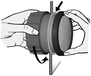
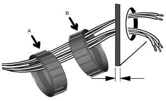
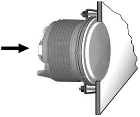
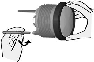
INSTALLATION INSTRUCTIONS: Viewline 85 mm
 1-10 1 Safety information The product was developed, manufactured and inspected according to the basic safety requirements of EC Guidelines and state-of-the-art technology. The unit is designed for use
Multi-Input Water/Methanol Injection Harness
 Multi-Input Water/Methanol Injection Harness 30-3324 WARNING: Improper installation and/or adjustment of this product can result in major engine/vehicle damage! Use of this injection system requires proper
Classic Instruments Ford. Installation Manual
 Classic Instruments 1940 Ford Installation Manual Table of Contents Welcome from the Team at Classic Instruments!... 3 Mount New Gauge Cluster... 4 Instrument Cluster Wiring... 5 Pulse Signal Generator
ODY-19-1 AIR PRESSURE GAUGE
 ODY-19-1 AIR PRESSURE GAUGE Introduction: The Odyssey gauge series from Dakota Digital, Inc. incorporates the reliability and quality of our standard gauges, along with several unique features and easy
Installation Instructions Receiver Rack (Part # 7700) Universal Application
 Universal Application") NOTE: Carefully read entire instructions thoroughly before attempting to install this part. Parts Included Qty Tools Needed 2 Draw Bar 1 Ratchet Racks 2 Socket Set Curved Support Bars 2 Wrench Set Connecting
NOTE: Carefully read entire instructions thoroughly before attempting to install this part. Parts Included Qty Tools Needed 2 Draw Bar 1 Ratchet Racks 2 Socket Set Curved Support Bars 2 Wrench Set Connecting
Lineum Star Phantom Model ULB48-TD
 Lineum Star Phantom Model ULB48-TD Dual Color Undercover Interior LED Lightbar IMPORTANT: Please read all of the following instructions before installing your new warning light. Please Note: These instructions
Full Sweep Minor Gauge Wiring:
 Full Sweep Minor Gauge Wiring: Notes on Senders: Temp Hi match/vdo 150C: Normally used in Oil temp, 140 280F. Temp Low match/vdo120c: Normally used in water temp, 100 240F. To test the gauges work (oil,
Switch select of sender types:
 Full sweep minor gauges wiring: B -------------------------------------------------- battery or +12V input. L -------------------------------------------------- LED illumination, for back lighting, dimmable.
Vehicle Security System
 Installation Instructions Vehicle Security System PROFESSIONAL INSTALLATION STRONGLY RECOMMENDED Installation Precautions: Roll down window to avoid locking keys in vehicle during installation Avoid mounting
Model Railroad Circuit Breaker (CB-1)
") Model Railroad Circuit Breaker (CB-1) User Manual Ring Engineering Inc. (219) 322-0279 www.ringengineering.com Revision 1.11 Copyright 2018 Ring Engineering Inc. All rights reserved. Introduction Thank
Model Railroad Circuit Breaker (CB-1) User Manual Ring Engineering Inc. (219) 322-0279 www.ringengineering.com Revision 1.11 Copyright 2018 Ring Engineering Inc. All rights reserved. Introduction Thank
TrimSync Race Edition Installation & Operating Instructions
 TrimSync Race Edition Installation & Operating Instructions Mounting the Device The unit should be mounted in a dry area away from sources of heat. Mounting the unit near the trim pumps will reduce wiring