Diagram D Parts of the Fuel Level Sender Unit to be Adjusted
|
|
|
- Leslie Crawford
- 5 years ago
- Views:
Transcription
1
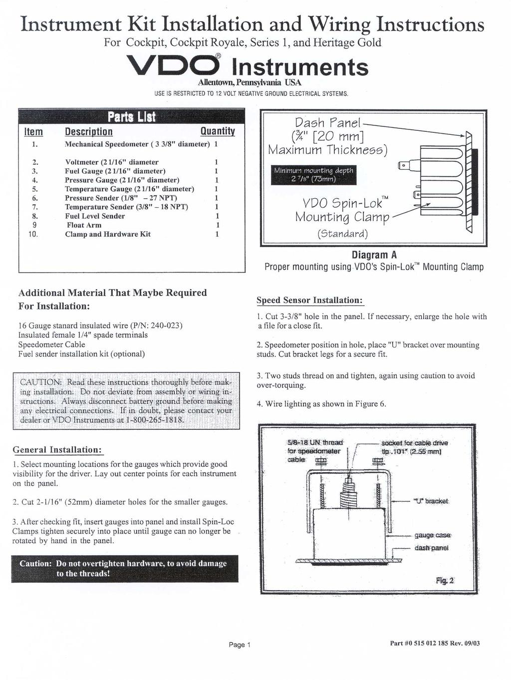
2 Fuel Level Sender Installation: The fuel sender in this kit has a resistance rating of 10 ohms when the tank is empty and 180 ohms when full. The unit can be adjusted to reqd accurately in tanks from 6-23" in tank depth. For sender adjustment refer to Table 1 and Diagram C. I. This fuel sender is designed to mount on all fuel tanks with a standard SAE five-hole flange configuration. If you tank does not have this configuration it may be necessary to purchase our optional flange kits refereed to on the front page of these instructions. II. Measure the tank depth of your fuel tank. Locate this demension in Column A of Table 1.. Reading across to Column B you will find the dimension from the mounting flange to the float pivot you will need to adjust the fuel sender to. If this dimension is 15-1/2" or greater proceed to Section A for adjustment details. If less than 15-1/2" proceed to Section B for adjustment details. Section A: (Tank depths less than 15-1/4") 1. Loosen the two screws marked 'd' in Diagram D. Adjust the plastic housing up or down until the proper dimension from Table 1 is obtained. Re-tighten screws until secure. Section B: (Tank depths less than 15-1/4") 1. Remove nut 'a' and washer 'b' to wire lead. 2. Remove two screws marked 'd' and discard. 3. On reverse side of sender locate two screws in plastic housing marked 'e'. 4. Slide plastic housig off of bracket 'f' and discard. 5. Install plastic housing by sliding on to bracket 'g' and reinstalling screws loosely. 6. Slide housing up or down until proper dimension from Table 1 is reached, then tighten screws. 7. Rap excessive lead wire around bracket 'g' and re-install with nut and washer. Float Installation: 1. Loosen pivot screw 'h' removing shot metal rod show in Diagram D. 2. Install float rod to proper dimension found in Table 1, Column C and tighten pivot screw. Note: You must install so float ball is positioned to the sender body, when the float pivot is facing you. If you have found that your gauges reads backward after installation you have installed the float in backwards. To correct this you must disassemble and reposition the float. 3. Leaving 1" of float rod exposed on left of float pivot cut off excess float rod. As received, the unit will have a short lever arm installed. Loosen the screw and remove the short lever arm, and replace it with the long float arm and plastic float ball assembly. When the installation is finished, the arm length to the left (short side) of the screw must be 1".!! IMPORTANT!! CAUTION: When attaching the float arm to the sender body, make sure the float ball is to the right side as you face the unit, as shown in Diagram D. If you attach the float arm to the left of the sender body, or backwards, the fuel gauge will read FULL when the tank is actually empty! Diagram D Parts of the Fuel Level Sender Unit to be Adjusted Note: In some installations if it is necessary to have the float pointed in the opposite direction. to accomplish this do not reposition the float. You must remove the two screws marked 'd'. Slide plastic housing off of bracket, rotate and reinstall to the proper dimension. CAUTION: Do not overtighten hardware, to avoid damage to the threads! WDQN &µ IXHO OHYHO VHQGHU %µ IORDW $µ Diagram C Measurements Needed To Make Proper Adjustments Page 2 TABLE 1 (dimensions in inches) A B C A B C A B C
3 Page 3
4 VOLTAGE WIRING OF POWER AND GROUND TO EACH GAUGE LEGEND Sender Wire: S or G Wire: or 12Volt Wire: () Diagram G Wiring Diagram ILLUMINATION WIRING AND WIRING OF SENDERS TO EACH GAUGE fuse dashlight switch pressure sender temperature sender fuel sender Electrical Wiring: Refer to the wiring diagram, Diagram G. Wire gauges in series from a positive () accessory to a source which is not already overloaded with fans, air conditioning, and such. The ground ( ) wire is also run in series, including the light socket ground. The final ground run, using 14-gauge wire, should be connected to a good ground such as the engine block ground strap or directly to the negative battery post. NOTE: See the separate Speedometer Installation and Operation Instructions for information on wiring the speedometer. System Testing: When installation and wiring has been completed, the following tests should be performed to ensure that all systems are functioning properly. I. Turn on the dash light switch to see if all gauges light up. If not, check your wiring, the ground, and all bulbs. Reconnect or replace as necessary. II. Turn on the ignition key. Gauges should read: Pressure: Needle to 0 Fuel: Needle to amount of fuel in the tank Temperature: Needle to the temperature of the engine water a) With the key on, pull the sender wire off of the sender: Fuel and pressure gauges: needle to the right-hand position Temperature gauge: needle to the left-hand position b) With the key on, ground the sender wire to the engine block: Fuel and Pressure Gauges: needle to the left-hand position Temperature Gauge: needle to the right-hand position NOTE: All VDO electrical gauge pointers will peg full lefthand position when the key is off. III. Senders can be tested with an ohmmeter that measures from 10Ω to 2000Ω. Connect the positive () lead from the tester to the sender terminal, and the negative ( ) lead to a good ground. The following readings should occur if the sender is operating properly: Temperature sender engine cold: 700Ω engine approximately 180 : 68Ω Pressure sender engine off: 10 Ω engine running 40 psi: 105 Ω engine running 60 psi: 152 Ω IV. Voltmeter: Volts: Key on, engine off: 12 Engine running, no accessories or lights: Engine running with accessories, lights: NOTE: These readings are approximate, depending on the regulator system and engine speed. Lower readings indicate a bad battery, regulator, or alternator; or incorrect wiring. V. With VDO fuel tank senders (Part # ), an empty tank will read 10Ω. As fuel is added, the resistance reading will rise until the tank is full, when it will read 180Ω. NOTE: If you already have a fuel level sender in your tank, check the resistance readings. If they do not match the readings above, VDO manufactures a number of fuel gauges which should match your sender. REMEMBER: The ohm range of the sender and the gauge MUST MATCH! VDO North America warrants all merchandise against defects in factory workmanship and materials for a period of 24 months after purchase. This warranty applies to the first retail purchaser and covers only those products exposed to normal use or service. Provisions of this warranty shall not apply to a VDO product used for a purpose for which it is not designed, or which has been altered in any way that would be detrimental to the performance or life of the product, or misapplication, misuse, negligence or accident. On any part or product found to be defective after examination by VDO North America, VDO North America will only repair or replace Siemens VDO Limited Warranty Page 4 the merchandise through the original selling dealer or on a direct basis. VDO North America assumes no responsibility for diagnosis, removal and/or installation labor, loss of vehicle use, loss of time, inconvenience or any other consequential expenses. The warranties herin are in lieu of any other expressed or implied warranties, including any implied warranty of merchantability or fitness, and any other obligation on the part of VDO North America, or selling dealer. (NOTE: This is a Limited Warranty as defined by the Magnuson- Moss Warranty Act of 1975.) Siemens VDO. Phone:
5 Hour Meter Terminal Hour Meter Terminals ( ) Clock Terminals ( ) Diagram B Clock Wiring Diagram Constant 12v ( ) ( Pressure ) Option 1 - Diagram C Engine Hourmeter Wiring Diagram Option 2 - Diagram C Engine Hourmeter Wiring Diagram DO NOT OVERTIGHTEN! SiemensVDO Limited Warranty Siemens VDO warrants all merchandise against defects in factory workmanship and materials for a period of 24 months after purchase. This warranty applies to the first retail purchaser and covers only those products exposed to normal use or service. Provisions of this warranty shall not apply to a Siemens VDO product used for a purpose for which it is not designed, or which has been altered in any way that would be detrimental to the performance or life of the product, or misapplication, misuse, negligence or accident. On any part or product found to be defective after examination by SiemensVDO, Siemens VDO will only repair or replace the merchandise through the original selling dealer or on a direct basis. Siemens VDO assumes no responsibility for diagnosis, removal and/or installation labor, loss of vehicle use, loss of time, inconvenience or any other consequential expenses. The warranties herin are in lieu of any other expressed or implied warranties, including any implied warranty of merchantability or fitness, and any other obligation on the part of Siemens VDO, or selling dealer. Siemens VDO. Phone: Siemens VDO Clock/Engine Hourmeter Installation Instructions Instruction Sheet # Rev. 10/03 -!"f C A UT ION: R ea d these ins tructions thoroughly before making installation. Do not deviate from assembly or wiring instructions. Mounting Nut direction depends on panel w idt h A: 0.4" (0 10 mm) CAUTION: B: Read.4".8 " (10 these 20 mm) instructions t ç TOP: VDO s Spin-Lok ä Mounting Clamp LEFT: VDO Mounting Bracket Diagram A - Mounting using optional VDO Mounting Bracket or VDO Spin-Lok Clamp é Instrument Mounting Diagram A: 1. Prior to any work on vehicle's wiring system, removing the (-) negative battery cable from the battery to disable battery power. 2. Find a suitable location to mount the instrument where there is ample depth to secure and wire instrument. 3. Cut a 2 1/16" (52 mm) diameter hole in the location selected. Instrument should fit into hole easily without forcing. Forcing it may cause damage to housing of instrument. 4. Secure 'Spin Lok' clamp (Diagram A) on to instrument. (Note) the 'Spin Lok' clamp is designed to work in thin panels as well as panels up to.8" (20 mm) in thickness. Consequently, if 'Spin Lok' clamp is installed and will not securely fasten instrument, remove, reverse and re-install. 5. If you are using optional metal mounting bracket, install with mounting nuts, For thicker panels it may be necessary to trim legs accordingly. Clock Wiring Digram C: 1. Wire terminal to a fused 12 v battery source that is not switched off when vehicle ignition is off. 2. Wire - terminal to a good ground location. 3. If the instrument you have purcased test for operation. CAUTION!!! Secured with Spin- Lok or metal braket tight enough to prevent rotation of instrument. DO NOT OVER TIGHTEN INSTRUMENT OR DAMAGE WILL OCCURE TO HOUSING AND BEZEL. Hour Meter Wiring Option 1- Digram C: 1. Wire terminal to a fused 12/24v battery source that is switched off when vehicle is not in operation. 2. Wire - terminal to a good ground location. 3. If the instrument you have purcased test for operation. (Note) Since the hourmeter registers in 10 th of hours, it will take 6 minutes before hourmeter will show movement. Hour Meter Wiring Option 2 - Digram C: 1. Wire terminal to a fused 12/24v battery source that remains on even vehicle igniton is off. 2. Wire - terminal directly to a normally open engine oil pressure switch. When engine is started and oil pressure CAUTIO rises the pressue switch will close and CAUTION the hour meter will begin to operate. 3. If the instrument you have purchased start vehicle. When oil pressure present observe operation of instrument. (Note) Since the hourmeter registers in 10 th of hours, it will take 6 minutes before hourmeter will show movement. Clock Setting 1. Button on bottom left of clock face will set counter clock wise 2. Button on bottom right of clock face will set clock wise 3. By hold left or right button down will make the clock set faster
➊ BEGIN HERE. Siemens VDO Quartz Clock/Engine Hourmeter Installation Instructions. Parts List. Diagram C VDO Engine Hourmeter Wiring

BEGIN HERE except CAUTION: DO NOT OVERTIGHTEN. Wiring the Voltmeter: IMPORTANT: Voltmeter Installation: CAUTION!!! Parts List
 BUb_VF_\d]UdUb
Gauge Installation Instructions
 Gauge Installation Instructions TEMPERATURE, PRESSURE AND FUEL LEVEL GAUGES VOLTMETER RUDDER POSITION INDICATOR A. Disconnect battery. B. Cut 2-3/32" hole in a suitable position in dash. Make sure rear
Gauge Installation Instructions
 Gauge Installation Instructions TEMPERATURE, PRESSURE AND FUEL LEVEL GAUGES VOLTMETER RUDDER POSITION INDICATOR A. Disconnect battery. B. Cut 2-3/32" hole in a suitable position in dash. Make sure rear
➊ BEGIN HERE. Siemens VDO Mechanical Temperature Gauge Installation Instructions. Parts List
 To Mount: Slip Mounting Bracket over studs on back of gauge. Align the gauge for easy readability, then tighten the nuts until the gauge no longer rotates in the panel. Do Not Overtighten. Diagram C Proper
BEGIN HERE except CAUTION: DO NOT OVERTIGHTEN. Wiring the Voltmeter: IMPORTANT: Voltmeter Installation: CAUTION!!! Parts List
 BUQb_VF_\d]UdUb
Tachometer. Installation and Operation Instructions
 THE INSTRUCTIONS FOR INSTALLATION AND ELECTRICAL WIRING FOR THESE TACHOMETERS FOLLOW. USE IS RESTRICTED TO 12 VOLT NEGATIVE GROUND ELECTRICAL SYSTEMS. Parts List Item Description Quantity 1. Tachometer
Speedo With Telltales and Display 85mm Tech Support Instruction Sheet # A2C Rev
 Gauge Installation: 1. Select the desired mounting location of the instrument. 2. Depending on your mounting situation it might be necessary to configure the gauge before installation. See page 2 - Setting
Viewline Instrument Kit Installation Instructions. Rev E. Important Installation Notes:
 Read these instructions thoroughly before installation. Do not deviate from assembly or wiring diagram. Always disconnect battery ground before making any electrical connections. IMPORTANT: Mounting dimensions
Siemens VDO Phone:
 Siemens http://sso-usa.siemensvdo.com/ Phone: 1-800-265-1818 !" # %]]! "&]] # ( ]] # (%]]!!( # ]] BUT4_d GXYdU4_d ## ($]] If you have any doubts, please contact your dealer or Instruments at 1-800-265-1818.
Tachometer Installation and Operation Instructions Addendum for Dual Shift Point (DSP) Eliminator Tachometer
 Eliminator Tachometer") Tachometer Installation and Operation Instructions Addendum for Dual Shift Point (DSP) Eliminator Tachometer Siemens VDO Allentown, Pennsylvania USA THE INSTRUCTIONS FOR OPERATION AND ELECTRICAL WIRING
Tachometer Installation and Operation Instructions Addendum for Dual Shift Point (DSP) Eliminator Tachometer Siemens VDO Allentown, Pennsylvania USA THE INSTRUCTIONS FOR OPERATION AND ELECTRICAL WIRING
I. Mounting the Tachometer
 Siemens Tachometer Installation and Operation Instructions for Programmable Tachometer with Hourmeter Instruction Sheet #0 515 012 037 Rev. 03/01 INSTRUCTIONS FOR THE INSTALLATION AND OPERATION OF THE
Digital Fuel Gauge P/n (With Dual Ohms Range option)
") Digital Fuel Gauge P/n 301.530 (With Dual Ohms Range option) Green Brown Red 12V 90 Ohms 180 Ohms Ignition Gauge Rear View Green 180R (Sw S_180) Brown 90R (Sw S_90) 180 Ohms 90 Ohms Front Fuel tank unit
Digital Fuel Gauge P/n 301.530 (With Dual Ohms Range option) Green Brown Red 12V 90 Ohms 180 Ohms Ignition Gauge Rear View Green 180R (Sw S_180) Brown 90R (Sw S_90) 180 Ohms 90 Ohms Front Fuel tank unit
PCS GEAR SELECT MODULE USER GUIDE v4.0
 PCS GEAR SELECT MODULE USER GUIDE v4.0 Ph: 1.804.227.3023 www.powertraincontrolsolutions.com Powertrain Control Solutions 1 Introduction 1.1 Included Components 1 - GSM Cable Motor Enclosur 1 - GSM Driver
AURORA SERIES GAUGES FUEL GAUGE SUGGESTED TOOLS AND MATERIALS. 3 3 /8 in (85.7 mm) PARTS LIST
 PARTS LIST") GAUGE INSTALLATION. Select mounting locations for the fuel gauge. 2. Cut a 2 /6 (52 mm) diameter hole for the gauge and test for proper fitmate. 3. Tighten the gauge with the enclosed Aurora Mounting Clamp
GAUGE INSTALLATION. Select mounting locations for the fuel gauge. 2. Cut a 2 /6 (52 mm) diameter hole for the gauge and test for proper fitmate. 3. Tighten the gauge with the enclosed Aurora Mounting Clamp
VDO Marine Instruments
 VDO Marine Instruments VDO North America is a worldwide supplier of electronic information and control systems. Since 1921, we have been a leader in instrument and sensor technology, providing leading-edge
Flow Chart Programming Instructions for : Transmission Temperature 2 1/16 START HERE PROGRAM MAIN MENU
 Flow Chart Programming Instructions for : Transmission Temperature 2 1/16 START HERE PROGRAM MAIN MENU (Press one button at a time) MAIN MENU ONE AT A TIME DOWN UP - + NORMAL/DIAL BRIGHTNESS: Press the
INSTRUMENT PANEL Toyota Celica DESCRIPTION & OPERATION GAUGES SWITCHES TESTING - GAUGES FUEL GAUGE & WARNING LIGHT
 INSTRUMENT PANEL 1994 Toyota Celica 1994 ACCESSORIES & EQUIPMENT Toyota Motor Sales, U.S.A., Inc. - Instrument Panel Celica * PLEASE READ THIS FIRST * WARNING: Vehicles are equipped with a driver-side
4331 EUCALYPTUS AVE. ~~ CHINO, CA Fax FORD F-250/350 SUPER DUTY 4 WHEEL DRIVE
 4331 EUCALYPTUS AVE. ~~ CHINO, CA 91710 909-597-7800 Fax 909-597-7185 2001-2004 FORD F-250/350 SUPER DUTY 4 WHEEL DRIVE 2000-03 EXCURSION 4 WHEEL DRIVE FTS424-1BK 3.5 LIFT BOX KIT PARTS LIST: 1 EA. FRT.
INSTALLATION INSTRUCTIONS MECHANICAL GAUGES
 1062650-1966-77 MECHANICAL GAUGES QUESTIONS: If after completely reading these instructions you have questions regarding the operation or installation of your instrument(s), please contact Hardin Marine
POWER GEAR SLIDE-OUT MANUAL
 POWER GEAR SLIDE-OUT MANUAL Operation Guide FLUSH FLOOR SLIDE-OUT SYSTEM FOR AMERICAN COACH PRODUCTS 82-S0220-01 Rev. 1 AMERICAN COACH SLIDE-OUT MANUAL FLUSH FLOOR SYSTEM TABLE OF CONTENTS SECTION PAGE
5 Gauge Box Set IS0342
 Caution 5 Gauge Box Set IS0342 Rev. B ecr 8832 9/202 Disconnect the battery during installation. Tighten nuts on the back clamp only slightly more than you can tighten with your fingers. Six inch-pounds
Classic Instruments. Installation Manual
 Classic Instruments Installation Manual TABLE OF CONTENTS Welcome from the Team at Classic Instruments! 3 Mounting Gauges 4 4 Speedometer Wiring 5 4 Speedometer Wiring Diagram 5 16 Pulse Signal Generator
FLOOR JACK JACK STANDS ASSORTED METRIC AND S.A.E SOCKETS DRILL WITH ¼ and ½ BITS
 www.fabtechmotorsports.com 4331 EUCALYPTUS AVE ~~ CHINO, CA 91710 PHONE 909-597-7800 ** FAX 909-597-7185 2003-2007 DODGE RAM 2500 & 3500 4 WHEEL DRIVE FTS53000BK MULTIPLE FRONT SHOCK SYSTEM PARTS LIST:
TOOL LIST: (NOT INCLUDED) FLOOR JACK JACK STANDS ASSORTED METRIC AND S.A.E SOCKETS, & ALLEN WRENCHES DIE GRINDER WITH CUTOFF WHEEL
 FLOOR JACK JACK STANDS ASSORTED METRIC AND S.A.E SOCKETS, & ALLEN WRENCHES DIE GRINDER WITH CUTOFF WHEEL") www.fabtechmotorsports.com 4331 EUCALYPTUS AVE. ~~ CHINO, CA 91710 909-597-7800 FAX 909-597-7185 2000-08 FORD RANGER 2WD FTS98200-73 3.5 LIFT SPINDLES PARTS LIST: 1 EA. PASS. SPINDLE FTS98200-73P 1 EA.
www.fabtechmotorsports.com 4331 EUCALYPTUS AVE. ~~ CHINO, CA 91710 909-597-7800 FAX 909-597-7185 2000-08 FORD RANGER 2WD FTS98200-73 3.5 LIFT SPINDLES PARTS LIST: 1 EA. PASS. SPINDLE FTS98200-73P 1 EA.
6 Gauge Box Set IS0333
 Caution 6 Gauge Box Set IS0 Rev. B ecr 882 9/202 Disconnect the battery during installation. Tighten nuts on the back clamp only slightly more than you can tighten with your fingers. Six inch-pounds of
Chevrolet. Installation Manual
 1959 1960 Chevrolet Installation Manual TABLE OF CONTENTS Welcome from the Team at Classic Instruments!... 3 Mount Adapter Ring... 4 Mount New 4-5/8 Gauge in Center Gauge Pod... 4 Mount New 2-1/8 Gauges
TOOL LIST: (NOT INCLUDED) FLOOR JACK JACK STANDS ASSORTED METRIC AND S.A.E SOCKETS, & ALLEN WRENCHES DIE GRINDER WITH CUTOFF WHEEL
 FLOOR JACK JACK STANDS ASSORTED METRIC AND S.A.E SOCKETS, & ALLEN WRENCHES DIE GRINDER WITH CUTOFF WHEEL") www.fabtechmotorsports.com 4331 EUCALYPTUS AVE. ~~ CHINO, CA 91710 909-597-7800 FAX 909-597-7185 2000-08 FORD RANGER 2WD FTS98200-7 3.5 LIFT SPINDLES PARTS LIST: 1 EA. PASS. SPINDLE FTS98200-7P 1 EA. DRIV.
www.fabtechmotorsports.com 4331 EUCALYPTUS AVE. ~~ CHINO, CA 91710 909-597-7800 FAX 909-597-7185 2000-08 FORD RANGER 2WD FTS98200-7 3.5 LIFT SPINDLES PARTS LIST: 1 EA. PASS. SPINDLE FTS98200-7P 1 EA. DRIV.
BATHROOM ACCESSORIES
 BATHROOM ACCESSORIES ORCA HARDWARE WARRANTY Orca Hardware warrants its products manufactured to be free from defects in materials and workmanship for a period of ten (10) years from the date of purchase,
6 Gauge Box Set IS0332
 Caution 6 Gauge Box Set IS0 Rev. A ecr 878 /0 Disconnect the battery during installation. Tighten nuts on the back clamp only slightly more than you can tighten with your fingers. Six inch-pounds of torque
CHECK THE FACTORY PITMAN ARM SPLINE ORIENTATION WITH THE SUPPLIED PITMAN ARM BEFORE BEGIN INSTALLATION. SEE STEP 8 FOR MORE INFORMATION.
 4331 EUCALYPTUS AVE. ~~ CHINO, CA 91710 909-597-7800 Fax 909-597-7185 2001-2004 FORD F-250/350 SUPER DUTY 2 WHEEL DRIVE 2000-2005 FORD EXCURSION 2 WHEEL DRIVE FTS413 DROP BRACKET KIT FTS413 BOX KIT FT30329
Assembly, Use and Care
 Model 2000 SR Professional Rotary Spreader Assembly, Use and Care Thank You! You have purchased the highest quality professional broadcast spreader available on the market today. The Model 2000 SR is the
DODGE RAM 2500 & WHEEL DRIVE FTS53002 MULTIPLE FRONT SHOCK SYSTEM
 2009-2010 DODGE RAM 2500 & 3500 4 WHEEL DRIVE FTS53002 MULTIPLE FRONT SHOCK SYSTEM Fabtech Motorsports 4331 Eucalyptus Ave. Chino, CA 91710 Tech Line 909-597-7800 Fax 909-597-7185 Web www.fabtechmotorsports.com
4331 EUCALYPTUS AVE. CHINO, CA PHONE FAX
 www.fabtechmotorsports.com 4331 EUCALYPTUS AVE. CHINO, CA. 91710 PHONE 909-597-7800 FAX 909-597-7185 FTS22115 Dirt Logic 2.25 Dual Steering Stabilizer System 2000-2004 Ford F250 & F350 4WD PARTS LIST:
Table of Contents. Technical Information Warning Statement
 Table of Contents Technical Information-----------------------------------1 Warning Statement--------------------------------------2 Read Before Riding-------------------------------------3 List of Parts-----------------------------------------------4
Operator Manual For use with WFCO ULTRA III Deckmount Converter WF-9800 Series (model number located on the cover of the unit)
") Operator Manual For use with WFCO ULTRA III Deckmount Converter WF-9800 Series (model number located on the cover of the unit) Distributed in the U.S.A. and Canada by ARTERRA DISTRIBUTION Warranty Service
Operator Manual For use with WFCO ULTRA III Deckmount Converter WF-9800 Series (model number located on the cover of the unit) Distributed in the U.S.A. and Canada by ARTERRA DISTRIBUTION Warranty Service
6 Gauge Box Set with Programmable Speedometer. Made in the USA. Caution. Speedometer Parts. Tachometer Parts. Fuel Level Gauge Parts.
 6 Gauge Box Set with Programmable Speedometer Caution Disconnect the battery during installation. Tighten nuts on the backclamp only slightly more than you can tighten with your fingers. Six inch-pounds
NORMAL/DIAL BRIGHTNESS: Press the down or up button to adjust dial brightness. Press the center button to save and advance to PEAK PLAYBACK.
 Flow Chart Programming Instructions for : Pyrometer (ETG) PROGRAM MAIN MENU (Press one button at a time) 2 1/16 Monitor START HERE MAIN MENU ONE AT A TIME DOWN UP - + NORMAL/DIAL BRIGHTNESS: Press the
Deere G & GP Series Snow Wing Installation
 Deere G & GP Series Snow Wing Installation Model: Serial Number: Rev. 10/13 Rylind Manufacturing, Inc. 2801 Youngfield St Suite 250 Golden, CO 80401 Offices: 303-979-3548 Fax: 303-979-4730 www.rylind.com
4.5 LIFT BOX KIT DODGE RAM 2500 & WD 7.3 DIESEL ONLY
 4.5 LIFT BOX KIT 2009 2010 DODGE RAM 2500 & 3500 4WD 7.3 DIESEL ONLY Fabtech Motorsports 4331 Eucalyptus Ave. Chino, CA 91710 Tech Line 909-597-7800 Fax 909-597-7185 Web www.fabtechmotorsports.com 4.5
HUSTLER 7' & 8' POOL TABLE ASSEMBLY INSTRUCTIONS
 HUSTLER 7' & 8' POOL TABLE ASSEMBLY INSTRUCTIONS NG2515PB/NG2520PB THANK YOU! Thank you for purchasing this product. We work around the clock and around the globe to ensure that our products maintain the
DODGE TRUCK INSTALLATION INSTRUCTIONS /2500/3500 PICKUP KIT SUM /2500/3500 PICKUP KIT SUM
 DODGE TRUCK INSTALLATION INSTRUCTIONS 1994-1996 1500/2500/3500 PICKUP KIT SUM-7866300 1997-1999 1500/2500/3500 PICKUP KIT SUM-7867300 Installation of a body lift will change the center of gravity and the
4331 EUCALYPTUS AVE. ~~ CHINO, CA Fax FORD F-250/350 SUPER DUTY 4 WHEEL DRIVE FTS
 4331 EUCALYPTUS AVE. ~~ CHINO, CA 91710 909-597-7800 Fax 909-597-7185 2000-2003 FORD F-250/350 SUPER DUTY 4 WHEEL DRIVE FTS421-1 5.5 & 8 LIFT BOX KIT PARTS LIST: 1 EA. TRACK ARM BRKT. FT423-100 1 EA. PITMAN
FORD SUPER DUTY 8 BASIC SYSTEM
 4331 EUCALYPTUS AVE. ~~ CHINO, CA 91710 909-597-7800 Fax 909-597-7185 2005-2007 FORD F-250/350 SUPER DUTY 4WD FTS22095 8 BASIC KIT 2005-07 FORD SUPER DUTY 8 BASIC SYSTEM 4331 EUCALYPTUS AVE. ~~ CHINO,
BE 30 BODY ELECTRICAL SYSTEM. Combination Meter COMBINATION METER. Parts Location
 BE30 BODY ELECTRICAL SYSTEM COMBINATION METER Parts Location BODY ELECTRICAL SYSTEM BE31 Meter Circuit (w/o Tachometer) No. 2 7 9 12 1 2 3 5 7 9 3 Wiring connector side ETC Pattern select switch A/T Oil
Model A Turn Signal Kit Installation Guide
 Model A Turn Signal Kit Installation Guide Creative Connections, Inc. Consumer Hot Line: 888-471-LOGO 770-476-7322 In Atlanta, GA http://www.logolites.com P/N: 100-005/K 2008 Creative Connections, Inc.
CRUISE CONTROL SYSTEM
 CRUISE CONTROL SYSTEM 1993 Mitsubishi Montero 1993 ACCESSORIES & EQUIPMENT Mitsubishi Cruise Control Systems Montero DESCRIPTION & OPERATION The cruise control system is electronically and vacuum controlled.
GM WD 2WD SUV REAR SYSTEM
 www.fabtechmotorsports.com 4331 EUCALYPTUS AVE. CHINO, CA. 91710 PHONE 909-597-7800 FAX 909-597-7185 2007-09 GM 1500 4WD 2WD SUV REAR SYSTEM FTS21051BK REAR AUTO RIDE COIL SPRING SYSTEM FTS21052BK REAR
Operating Manual. 2012, 2024, and 2026 Soil Sampler th AVE N Fargo, ND Phone: (701) Web: farmqa.com
 Web: farmqa.com") Operating Manual 2012, 2024, and 2026 Soil Sampler 2800 7th AVE N Fargo, ND 58102 Phone: (701) 237-2167 Web: farmqa.com AMITY TECHNOLOGY, LLC PRODUCT WARRANTY Amity Technology, LLC warrants to the original
Operating Manual 2012, 2024, and 2026 Soil Sampler 2800 7th AVE N Fargo, ND 58102 Phone: (701) 237-2167 Web: farmqa.com AMITY TECHNOLOGY, LLC PRODUCT WARRANTY Amity Technology, LLC warrants to the original
Installation Instructions
 Installation Instructions FTL5107 2007-2016 GM 1500 TRUCK & SUV 2 LEVELING KIT 4331 EUCALYPTUS AVE. CHINO, CA. 91710 PHONE 909-597-7800 FAX 909-597-7185 FTL5107 2007-2016 GM 1500 TRUCK & SUV 2 LEVELING
Installation Instructions
 Installation Instructions 4 Basic Suspension System 1997-2006 JEEP TJ 4WD Fabtech Motorsports 4331 Eucalyptus Ave. Chino, CA 91710 Tech Line 909-597-7800 Fax 909-597-7185 Web www.fabtechmotorsports.com
RENEGADE SLATE BUMPER POOL TABLE ASSEMBLY INSTRUCTIONS
 RENEGADE SLATE BUMPER POOL TABLE ASSEMBLY INSTRUCTIONS NG2404PG THANK YOU! Thank you for purchasing this product. We work around the clock and around the globe to ensure that our products maintain the
PLAYOFF 48" FOOSBALL TABLE ASSEMBLY INSTRUCTIONS
 PLAYOFF 48" FOOSBALL TABLE ASSEMBLY INSTRUCTIONS NG1031F THANK YOU! Thank you for purchasing this product. We work around the clock and around the globe to ensure that our products maintain the highest
CHEVY / GMC 1500HD / 2500HD 2WD 8 LUG 7 BASIC KIT
 85101 2000-2010 CHEVY / GMC 1500HD / 2500HD 2WD 8 LUG 7 BASIC KIT C8510-4 MAIN BOX KIT W/ HARDWARE 1) FRONT X MEMBER 1) REAR X MEMBER 2) TORSION BAR DROPS 1) LEFT BUMP STOP 1) RIGHT BUMP STOP 2) SWAY BAR
INSTALLATION INSTRUCTIONS
 #52180C3 Corvette Radiator & Fan Kits #52181C3 Fits 1968-1972 Fits 1970-1982 Chevrolet Corvette C3 Note: Manual transmission preferred; automatic transmission requires a remote cooler. (pt. #4116C3 available)
TOOL LIST: (NOT INCLUDED) FLOOR JACK AND JACK STANDS ASSORTED METRIC AND S.A.E SOCKETS, & ALLEN WRENCHES DIE GRINDER WITH CUTOFF WHEEL AND MIG WELDER
 FLOOR JACK AND JACK STANDS ASSORTED METRIC AND S.A.E SOCKETS, & ALLEN WRENCHES DIE GRINDER WITH CUTOFF WHEEL AND MIG WELDER") www.fabtechmotorsports.com 4331 EUCALYPTUS AVE. ~~ CHINO, CA 91710 909-597-7800 FAX 909-597-7185 1997-2003 FORD F150 2 WHEEL DRIVE FTS97150-11 FRONT LONG TRAVEL KIT PARTS LIST: 1 EA. (UCA) PASSENGER S
www.fabtechmotorsports.com 4331 EUCALYPTUS AVE. ~~ CHINO, CA 91710 909-597-7800 FAX 909-597-7185 1997-2003 FORD F150 2 WHEEL DRIVE FTS97150-11 FRONT LONG TRAVEL KIT PARTS LIST: 1 EA. (UCA) PASSENGER S
Installation Instructions FTS51008BK GM K2500 SUV Auto Ride Shock Mount Kit
 Installation Instructions FTS51008BK 6 01-05 GM K2500 SUV Auto Ride Shock Mount Kit Parts List: 2 FT20127BK SHK EXT 6" FRT 2500 AR MNT 2 FT20130BK SHK EXT 6" RR 2500 AR MNT 2 FT20131BK SHK EXT 6" RR 2500
MLS KICK-OFF TABLETOP SOCCER TABLE ASSEMBLY INSTRUCTIONS
 MLS KICK-OFF TABLETOP SOCCER TABLE ASSEMBLY INSTRUCTIONS NGD1028 1 THANK YOU! Thank you for your purchase of this Harvil product. We work around the clock and around the globe to ensure that Harvil products
22421 SPORT SWAY BAR SET TOYOTA COROLLA
 22421 SPORT SWAY BAR SET 98-01 TOYOTA COROLLA Thank you for your purchase from our line of Corolla parts. Please call us at (877) 4NO-ROLL if you have any questions regarding the service or installation
Chek-A-Cell TM. Instruction Manual Rev A 8/12
 Chek-A-Cell TM Instruction Manual 84-867 Rev A 8/12 INTRODUCTION: The CHEK-A-CELL is a digital battery load tester for all types of batteries in the 5.75 Volt to 20 Volt, 1 to 20 Amp Hour range. Rechargeable
5) The trailing arm should then pivot smoothly on the chassis. 6) Install the rear bolt. 7) Place one drop of blue Loctite
 The trailing arm should then pivot smoothly on the chassis. 6) Install the rear bolt. 7) Place one drop of blue Loctite") INSTALLATION INSTRUCTIONS 1301 / 1302 / 1305 / 1306 THANK YOU FOR CHOOSING HOTCHKIS PERFORMANCE PRODUCTS Removal of Stock Lower Trailing Arms 1) Place car on level surface. 2) Support rear of the car on
INSTALLATION INSTRUCTIONS 1301 / 1302 / 1305 / 1306 THANK YOU FOR CHOOSING HOTCHKIS PERFORMANCE PRODUCTS Removal of Stock Lower Trailing Arms 1) Place car on level surface. 2) Support rear of the car on
INSTALLATION INSTRUCTIONS
 THANK YOU FOR CHOOSING KURYAKYN! Protect yourself and others from possible injury and property damage or loss. Pay close attention to all instructions, warnings, cautions, and notices regarding the installation,
JOHNSON/EVINRUDE 9.9 & 15HP SUZUKI For motors see below
 JOHNSON/EVINRUDE 9.9 & 15HP 2003-2010 SUZUKI 2003-2011 For motors 2005-2011 see below TrollMaster is a precision throttle control designed to achieve the maximum in trolling speed accuracy. The memory
OPERATOR S MANUAL MODEL GC-SFZ
 R Made in the USA by MODEL GC-SFZ THIS MANUAL CONTAINS THE OPERATING INSTRUCTIONS AND SAFETY INFORMA- TION FOR YOUR SCAG ACCESSORY. READ- ING THIS MANUAL WILL PROVIDE YOU WITH MAINTENANCE AND ADJUSTMENT
4331 EUCALYPTUS AVE. CHINO, CA
 www.fabtechmotorsports.com 4331 EUCALYPTUS AVE. CHINO, CA. 91710 PHONE 909-597-7800 FAX 909-597-7185 2000-2001 DODGE RAM 1500 4 WHEEL DRIVE 1994-2001 DODGE RAM 2500 4 WHEEL DRIVE FTS3420 5 1/2 LIFT BOX
Installation Manual TWM Performance Full replacement short shifter assembly Civic all trims and models
 Installation Manual TWM Performance Full replacement short shifter assembly 2006+ Civic all trims and models Begin the installation by parking on a flat surface, as you will have to engage and disengage
Operator Manual For use with WFCO ULTRA III Power Center WF-9900 Series (model number located on the door assembly label)
") Operator Manual For use with WFCO ULTRA III Power Center WF-9900 Series (model number located on the door assembly label) Distributed in the U.S.A. and Canada by ARTERRA Distribution Warranty Service (877)
Operator Manual For use with WFCO ULTRA III Power Center WF-9900 Series (model number located on the door assembly label) Distributed in the U.S.A. and Canada by ARTERRA Distribution Warranty Service (877)
INSTRUCTIONS TUBULAR CONTROL ARMS & COIL-OVER CONVERSION FOR AMC MUSCLE CARS: 1970 AMX JAVELIN SPIRIT, HORNET, GREMLIN, CONCORD
 AMC TUBULAR CONTROL ARMS & COIL OVER KIT INSTRUCTIONS TUBULAR CONTROL ARMS & COIL-OVER CONVERSION FOR AMC MUSCLE CARS: 1970 AMX 1970-74 JAVELIN SPIRIT, HORNET, GREMLIN, CONCORD Revised 6/1/2012 www.freakride.com
Model Mast Adapter with 4-Foot Boom. User s Manual 1165 NATIONAL DRIVE SACRAMENTO, CALIFORNIA WWW. ALLWEATHERINC. COM
 Model 30319 Mast Adapter with 4-Foot Boom User s Manual 1165 NATIONAL DRIVE SACRAMENTO, CALIFORNIA 95834 WWW. ALLWEATHERINC. COM TABLE OF CONTENTS INTRODUCTION... 1 INSTALLATION... 2 CALIBRATION... 5 MAINTENANCE...
Installation Manual TWM Performance Short Shifter Subaru Forester up to 2005
 - 1 - Installation Manual TWM Performance Short Shifter Subaru Forester up to 2005 Please Note: It is preferable to park on a flat surface, as you will have to engage and disengage the hand brake and shift
FLEETWOOD TRAVEL TRAILER SLIDEOUT SYSTEM OWNER S MANUAL
 FLEETWOOD TRAVEL TRAILER SLIDEOUT SYSTEM OWNER S MANUAL 82-S0150-01 REV. 1 April, 2002 TABLE OF CONTENTS PAGE # OPERATIONS MANUAL... 1 1. SYSTEM DESCRIPTION... 1 1.1 MAJOR COMPONENTS... 1 2. HOW TO OPERATE
Electrometer Lead Acid Battery Replacement
 Electrometer Lead Acid Battery Replacement Table of Contents NOTE: Although this manual is provided by Standard Imaging as a reference, battery replacement by anyone other than a trained Standard Imaging
INSTALLATION INSTRUCTIONS
 08 YEARS: 07-CURRENT Safety glasses should be worn at all times while installing this product. INSTALLATION INSTRUCTIONS MODEL: RIDGELINE MAKE: HONDA STYLE: TRUCK WARNING: NEVER EXCEED YOUR VEHICLE MANUFACTURER'S
INSTALLATION INSTRUCTIONS
 INSTALLATION INSTRUCTIONS 1301 / 1302 / 1305 / 1306 THANK YOU FOR CHOOSING HOTCHKIS PERFORMANCE PRODUCTS Removal of Stock Lower Trailing Arms 1) Place car on level surface. 2) Support rear of the car on
Yukon Gear & Axle. D30, D44 & GM 8.5" Hardcore Locking Hub Installation Guide PLEASE READ COMPLETELY BEFORE INSTALLATION
 Yukon Gear & Axle D30, D44 & GM 8.5" Hardcore Locking Hub Installation Guide PLEASE READ COMPLETELY BEFORE INSTALLATION COPYRIGHT 2014 - Yukon Gear & Axle Application Guide: YHC70005 D30 & D44 30spl -
LESTRONIC II BATTERY CHARGER TAYLOR-DUNN MODEL TYPE 24LC25-8ET
 LESTRONIC II BATTERY CHARGER TAYLOR-DUNN 79-301-10 MODEL 13110-32 TYPE 24LC25-8ET AC Supply: DC Output: Battery Capacity: Specifications 120 volts, 60 Hertz, single-phase 24 volts, 32 amps Use only on
MAVERICK 7' POOL TABLE WITH TABLE TENNIS ASSEMBLY INSTRUCTIONS
 MAVERICK 7' POOL TABLE WITH ASSEMBLY INSTRUCTIONS NG1023 THANK YOU! Thank you for purchasing this product. We work around the clock and around the globe to ensure that our products maintain the highest
PFS Rotameter. Variable Area Flowmeter. Instruction Manual PFS-RM200, RM230, RM250
 PFS Rotameter 09/2018 Rev. 0 Variable Area Flowmeter Instruction Manual PFS-RM200, RM230, RM250 Please note: This instruction manual provides detailed information and instructions that must be read, understood
Service/Installation Manual Full Wall Slide Systems
 Service/Installation Manual Full Wall Slide Systems 7 East 7th Street Mishawaka, IN 65 888-9-57 Fax 57-56-67 www.powergearus.com 8-S079 Rev Page CONTENTS Page Major Components Full Wall Slide System Operation
HYDRAULIC LEVELING SYSTEMS OPERATIONS MANUAL (For systems with touch pad part number , , , , or no number at all)
") HYDRAULIC LEVELING SYSTEMS OPERATIONS MANUAL (For systems with touch pad part number 500089, 500105, 500210, 500456, 500535 or no number at all) Visit us on the web at www.powergearus.com 82-L0040-01 Rev.
HYDRAULIC LEVELING SYSTEMS OPERATIONS MANUAL (For systems with touch pad part number 500089, 500105, 500210, 500456, 500535 or no number at all) Visit us on the web at www.powergearus.com 82-L0040-01 Rev.
Installation Instructions PowerBoard Automatic Retracting Running Board
 Installation Instructions PowerBoard Automatic Retracting Running Board Vehicle Application Dodge Ram 1500 Crew Cab 2009 - Current : 75138-15 Dodge Ram 2500/3500 & HD Crew Cab 2010 - Current : 75138-15
31034 INSTALLATION INSTRUCTIONS
 0 INSTALLATION INSTRUCTIONS Safety glasses should be worn at all times while installing this product. YEARS: 00-PRESENT MAKE: HYUNDAI MODEL: SANTA FE STYLE: SUV WARNING: NEVER EXCEED YOUR VEHICLE MANUFACTURER'S
Installation Instructions FRONT SUSPENSION INSTRUCTIONS: 1) Disconnect the negative terminal on the battery.
 Disconnect the negative terminal on the battery.") 75004 75001-5 COPONENT BOX 1 1) Rear Cross Member 1) Front Cross Member 1) Left Strut Spacer 1) Right Strut Spacer 2) Sway Bar Drops 1) Left Compression Strut 1) Right Compression Strut 2) Tie rods T538
75004 75001-5 COPONENT BOX 1 1) Rear Cross Member 1) Front Cross Member 1) Left Strut Spacer 1) Right Strut Spacer 2) Sway Bar Drops 1) Left Compression Strut 1) Right Compression Strut 2) Tie rods T538
Installation Instructions / Warranty
 Installation Instructions / Warranty Allegro Gourmet 06460XX0 Allegro 06461XX0 Allegro Kitchen Faucet 06461XX0 Allegro Gourmet Kitchen Faucet 06460XX0 06460XX0 06461XX0 Product Specifications: Hole size
OPERATOR S MANUAL FABRIC 3-BAG GRASS CATCHER PART NO PRINTED 8/2012 PRINTED IN USA
 OPERATOR S MANUAL FABRIC -BAG GRASS CATCHER Models: GC-STC-V This manual contains the operating instructions and safety information for your Scag mower accessory. Reading this manual can provide you with
Installation Instructions PowerBoard Automatic Retracting Running Board
 Installation Instructions PowerBoard Automatic Retracting Running Board Vehicle Application Toyota Tundra Double Cab 2007 Current Part Number: 75136-15 Toyota Tundra CrewMax 2007 Current Part Number: 75137-15
Marine Products. SL-3 Engine Controls. Owner s Manual
 Marine Products SL-3 Engine Controls Owner s Manual This manual must be accessible to the owner/user of this Morse marine product. Includes installation, operation and maintenance instructions for your
Automated I.V. Stand Cat. No OPERATOR S MANUAL. Operation& Maintenance Instructions. Raising the Standard of Care!
 Automated I.V. Stand Cat. No. 741314 OPERATOR S MANUAL Operation& Maintenance Instructions Raising the Standard of Care! Table of Contents Warranty....................... 2 Hardware.......................
SPORT COIL SPRINGS Scion xa & xb Part #19412 INSTALLATION OF HOTCHKIS FRONT COIL SPRINGS
 SPORT COIL SPRINGS 2004+ Scion xa & xb Part #19412 Thank you for your purchase from our new line of Scion xa / xb parts. Please call us at (877) 4NO-ROLL if you have any questions regarding the service
INSTALLATION INSTRUCTIONS
 078 YEARS: 07-CURRENT Safety glasses should be worn at all times while installing this product. INSTALLATION INSTRUCTIONS MODEL: SUPER DUTY MAKE: FORD STYLE: TRUCK WARNING: NEVER EXCEED YOUR VEHICLE MANUFACTURER'S
12-Volt Negative Ground Installation Instructions
 12-Volt Negative Ground Installation Instructions For Part Number: 1183 CAUTION!!! Before installing, please read the following important information... 1. The Ignitor is designed for 12-Volt negative
User s Manual and Operating Instructions
 User s Manual and Operating Instructions Model Numbers: CL-36-BDF-A, CL-42-BDF-A, CL-48-BDF-A E355088 READ AND SAVE THESE INSTRUCTIONS IMPORTANT: Read and understand all of the instructions in this manual
AEROMOTIVE Part # & Mustang 5.0L Stealth Fuel System Kit INSTALLATION INSTRUCTIONS
 AEROMOTIVE Part # 18653 & 18654 86-93 Mustang 5.0L Stealth Fuel System Kit INSTALLATION INSTRUCTIONS CAUTION: Installation of this product requires detailed knowledge of automotive systems and repair procedures.
MODEL A97 SERIES. Switchmode Utility Rectifier/Battery Charger ECN/DATE
 MODEL A97 SERIES Switchmode Utility Rectifier/Battery Charger CPN108172 ISSUE DATE: 16071 7/03 ECN/DATE 106 BRADROCK DRIVE DES PLAINES, IL. 60018-1967 (847) 299-1188 FAX: (847)299-3061 Page 1 of 7 INSTRUCTION
31015 INSTALLATION INSTRUCTIONS
 0 INSTALLATION INSTRUCTIONS Safety glasses should be worn at all times while installing this product. YEARS: 00-CURRENT MAKE: DODGE RAM MODEL: 00 STYLE: TRUCK WARNING: NEVER EXCEED YOUR VEHICLE MANUFACTURER'S
Removing and installing dash panel insert
 Removing and installing dash panel insert Caution To disconnect and connect the battery, the procedure described in the workshop manual should be strictly adhered to Chapter. Note Pull off multi-pin connector
MOVE ON TO THE REAR BAR INSTALLATION
 22410 STREET SWAY BAR SET 2001-UP LEXUS IS300 Thank you for your purchase from our line of Lexus parts. Please call us at (877) 4NO-ROLL if you have any questions regarding the service or installation
OPERATOR S MANUAL MODEL GC-STC-V
 MODEL GC-STC-V THIS MANUAL CONTAINS THE OPERATING INSTRUCTIONS AND SAFETY INFORMA- TION FOR YOUR SCAG ACCESSORY. READ- ING THIS MANUAL WILL PROVIDE YOU WITH MAINTENANCE AND ADJUSTMENT PROCEDURES TO KEEP
HURRICANE 54-IN FOOSBALL TABLE ASSEMBLY INSTRUCTIONS
 HURRICANE 54-IN FOOSBALL TABLE ASSEMBLY INSTRUCTIONS Please Do Not Hesitate to Contact Our Consumer Hotline at 800-759-0977 with Any Questions That May Arise During Assembly or Use of This Product! NG1033F
Installation Manual TWM Performance Shift Boot 2006 and up Honda Civic Si
 Page 1 Installation Manual TWM Performance Shift Boot 2006 and up Honda Civic Si Begin the installation by parking on a flat surface, as you may have to engage and disengage the hand brake and shift from