W843-2 For Models: M843NW2, NL843NW2, and NL843N2 WORKSHOP MANUAL. Marine Generators Marine Diesel Engines Land-Based Generators
|
|
|
- Vernon McGee
- 5 years ago
- Views:
Transcription


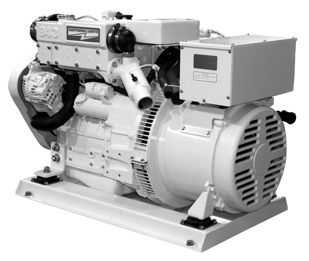
1 W843-2 For Models: M843NW2, NL843NW2, and NL843N2 WORKSHOP MANUAL Marine Generators Marine Diesel Engines Land-Based Generators
2 CALIFORNIA Proposition 65 Warning: Diesel engine exhaust and some of its constituents are known to the State of California to cause cancer, birth defects, and other reproductive harm. Northern Lights th Avenue N.W. Seattle, WA Tel: (206) Fax: (206) Copyright 2007 Alaska Diesel Electric, Inc. All rights reserved. Northern Lights, and the Northern Lights logo are trademarks of Alaska Diesel Electric, Inc. Printed in U.S.A. PART NO.:
3 WORKSHOP MANUAL for Models M843NW2, NL843NW2, and NL843N2 Alaska Diesel Electric reserves the right to carry out any design modifications and, for this reason, some of the contents of this manual may not apply to your engine. If further information is needed, we suggest that you contact an authorized dealer or the ADE factory. TABLE OF CONTENTS 1. Disassembly Procedures Safety Instructions REASSEMBLY of Engine Main Components Head Gasket Inspection of Engine Main Components a. Rocker Arm...9 b. Cylinder Head c. Cylinder Block...12 d. Piston & Piston Rings e. Connecting Rod f. Bearing Holder g. Crankshaft Bearing...16 h. Crankshaft...17 i. Flywheel & Ring Gear...17 j. Camshaft Assembly...18 k. Timing Gear...18 l. Oil Pump...19 m. Oil Filter...19 n. Coolant Pump...19 o. Thermostat...20 p. Radiator...20 q. Fuel Filter...20 r. Injection Pump...21 s. Nozzle and Holder Electrical System inspection Fuel Solenoid...31 Glow Plugs...32 Oil Pressure Switch Alternator Maintenance Chart...34 Alternator Troubleshooting...35 Starter Troubleshooting Engine Maintenance Standards Proprietary Information This publication is the property of Alaska Diesel Electric, Inc. It may not be reproduced in whole or in part without the written permission of Alaska Diesel Electric, Inc. Alaska Diesel Electric, Inc. All rights reserved. Litho U.S.A. Publication number 3
4 Introduction SAFETY RULES CAUTION: Accident reports show that careless use of engines causes a high percentage of accidents. You can avoid accidents by observing these safety rules. Study these rules carefully and enforce them on the job. Never leave engine without proper security. Turn the coolant tank cap slowly to relieve pressure before removing. Add coolant only when the engine is stopped and cool. Mount a fire extinguisher near engine. Always disconnect the battery ground strap before making adjustments. Operate engines in properly ventilated areas. Keep trash and other objects away from engine. Escaping fluids under pressure can penetrate your skin. Use a piece of cardboard or wood, not your hands, to search for leaks. Avoid wearing loose clothing without a belt when working around engines. Do not oil or grease engine while it is running. Use caution in handling fuel. Never refuel a hot or running engine. Do not smoke while filling fuel tank or servicing fuel system. Keep your hands, feet, hair and clothing away from power-driven parts. Check for any loose electrical connections or faulty wiring. Engines should be operated only by knowledgeable, qualified personnel. Look completely around engine to make sure that everything is clear and clean before starting. Do not operate an engine that isn't in proper working order. If an unsafe operating condition is noted, tag the set and control panel so others will also know about the problem. Provide first aid kits. Do not disassemble parts or engine except for what is needed to be worked on - as initially the engine was put together with precision that could prove hard to duplicate. Apply oil to moving parts during reassembly to form an oil film to fill up the gap before regular lubrication occurs. CAUTION: This symbol is used throughout this book to alert you to possible danger areas. Please take special notice of these sections. 4
5 SECTION 1 DISASSEMBLY PROCEDURES Engine Overall Disassembly ISMcylblockwithalt SEQUENCE PART DISASSEMBLY ESSENTIALS 1 Alternator 2 Oil Filter 3 Relief Valve 4 Dipstick 5 Engine stop solenoid, seal washer 6 Injection pipe 7 Injection pump assembly Remove the injection lines and stop solenoid before removing the injection pump. Raise the injection pump and disconnect the governor link from the control rack by removing the snap pin. The injection timing has been adjusted by the shims between the injection pump and cylinder block; record the thickness and number when removing the injection pump. 5
6 SECTION 1 DISASSEMBLY PROCEDURES Engine Overall Disassembly ISMblockwithrockercover SEQ. PART DISASSEMBLY ESSENTIALS 8 Return pipe 9 Injection nozzle, gasket 10 Oil transfer tube, banjo bolt, seal washer 11 Connector, glow plugs 12 Oil pressure switch 13 Thermostat housing, gasket 14 Rocker arm cover, o-ring, intake manifold, spacer 15 Rocker arm assembly, o-ring, cap Remove the caps from intake valves 16 Push rod and exhaust valves. 17 Cylinder head, head gasket Loosen the cylinder head bolts in 18 Tappet several steps and remove the cylinder head assembly. 6
7 SECTION 3 DISASSEMBLY PROCEDURES Engine Overall Disassembly ISMvbelt&fan SEQ. PART DISASSEMBLY ESSENTIALS 19 V-belt, cooling fan, fan housing, fan pulley 20 Water pump assembly, gasket 21 Crankshaft pulley 22 Timing gear case assembly, gasket First remove the injection pump 23 Idle gear, oil pump assembly assembly and the stop solenoid. 24 Cam shaft assembly, plate Remove the bolts and plate first and pull 25 Front plate, gasket out the camshaft assembly. 7
8 SECTION 1 DISASSEMBLY PROCEDURES Engine Overall Disassembly ISMblockwithcrankshaft SEQ. PART DISASSEMBLY ESSENTIALS 27 Oil pan, gasket, intake filter, intake pipe 28 Flywheel 29 Rear plate 30 Oil seal 31 Piston and connecting rod assembly Remove the carbon deposit from the top 32 Crankshaft and bearing holder assembly of the cylinder before taking out the piston. Keep the connecting rod, cap, and bearing in the order of the cylinders as they are removed. Take out the bolts for the bearing holders and remove the crankshaft and bearing holder as a set. 8
9 SECTION 2 Inspection PROCEDURES Engine Main Parts Inspection Notes before assembly: 1. Check for wear and leakage on the cylinder block and the cylinder head. 2. Check for clogs in oil holes on parts and remove deposits with air. 3. Wash each part completely to remove contaminates, oil, carbon, etc For the piston, cylinder, and valves take care in removing deposits (aluminum alloy parts need extra care). 5. Valves, pistons, connecting rods, metals, and other parts that are to be put back together should be marked with their matches so that they can be re-fitted with greater ease. A) Rocker Arm Assembly Disassembly and Inspection 1 Screw 2 Rocker arm shaft 3 Rocker arm Screw in a M8 bolt at the front end of the rocker arm 4 Spring shaft and take out the rocker arm shaft. 5 Shim Take out the spring, shim, and rocker arm from the rocker arm bracket. ISMinspec.pg1a 1 Using a micrometer, check outside diameter of the rocker arm shaft. If the shaft wear exceeds the service limit shown, replace it. Wear of rocker arm shaft (mm) Standard assembly value Service limit Measure the inside diameter of the rocker arm. Calculate the clearance between the rocker arm and rocker arm shaft. If the clearance is past the service limit replace the part. Clearance between rocker arm and rocker arm shaft (mm) Standard assembly value Service limit More than Check the valve cap-contact surface for uneven wear and streaks. Smooth the surface with an oilstone or grinder if needed. ISMinspec.pg1b 9
10 SECTION 2 Inspection PROCEDURES Engine Main Parts Inspection B) Cylinder Head Assembly 1 Valve guide seal 2 Spring 3 Retainer Using a valve spring replacer, compress the valve 4 Valve spring to remove the valve keeper, retainer, spring, 5 Valve keeper and valve. Then remove the valve guide seal. ISMinspec.pg2a ISMinspec.pg2b 1. To measure the distortion of the cylinder head bottom surface; apply a straight edge to the bottom surface of the cylinder head and insert a gauge to measure thickness at 6 points from A to F as shown above. If the distortion measured exceeds the repair value as shown below, smooth with a surface grinder or something similar. Distortion at cylinder head bottom surface (mm) Standard assembly value Repair value Less than 0.05 More than Valve guide and stem: Inspect the head and stem of each valve and replace if damaged or badly worn. Measure the outside diameter at 1,2,3 positions (figure at right) with a micrometer and replace if the result is less than the service limit as seen in the below table. ISMinspec.pg2c Wear of valve stem o (mm) Intake Valve Exhaust Valve Standard Service Standard Service assembly Limit assembly Limit value value Valve head: If the head thickness is less than the service limit below, replace. Valve head thickness (mm) Standard assembly value Service Limit Less than 0.5 ISMinspec.pg2d 10
11 SECTION 2 Inspection PROCEDURES Engine Main Parts Inspection 4. Valve Guide and Valve: If the clearance between the valve stem and guide exceeds the service limit, replace the valve. Clearance between valve stem and guide Intake Valve Exhaust Valve Standard Service Standard Service assembly Limit assembly Limit value value More than More than 0.25 ISMstem&guide 5. Valve Seat: Check the valve guide first for wear condition before correcting the valve seat as the valve seat is corrected according to the valve guide. Use seat cutter of 15, 45, and 75 to correct the seat to the standard assembling values. Valve Seat Contact Width (mm) Standard assembly value Repair value Intake Exhaust ISMvalveseatwidth 6. Replace the cylinder head if the seat recess exceeds the service limit. Distortion at cylinder head bottom surface (mm) Standard assembly value Repair value Less than 0.05 More than To correct the valve seat, coat the valve seat with compound and lap the contact surface turning the valve. Make sure the valve contact surface is within the standard value and the contact position is even. If the cylinder head is replaced with a new one, adjust the seat contact width and seat recess to the specified values (see above tables) with a seat cutter before lapping. ISMvalveseatrecess ISMvalvelapper 11
12 SECTION 2 Inspection PROCEDURES Engine Main Parts Inspection 8. Valve Spring Check the valve spring for damage. Measure the squareness of the spring using a square on a surface plate and if the surface limit is exceeded, replace the spring. Check the free length and spring force with a spring tester and replace the spring if the service limit is exceeded. Standard Service assembly value Limit Squareness (mm) Free Length Spring force (compressed 79.8 N 68.6 N to 30.4 mm) (8.1 kgf) (7 kgf) ISMspring Reassembly Reassemble the components in the reverse order to that previously discussed. Take care to not damage the valve guide seal when assembling the valve spring, retainer, and cotter. Tighten the glow plugs to: N m (1.5~2.0 kgf m) C. Cylinder Block Check for cracks and damage on the top of the block just like on the cylinder head. There should be no scratches, rust, or corrosion in the cylinder bore. Measure the cylinder bore at the top, center, and the bottom in the crankshaft direction (A on figure to the right) and also right angle to it (B). Replace the engine long block if the repair value in exceeded. Distortion at cylinder block top surface (mm) Standard assembly value Repair value Less than 0.05 More than 0.12 Cylinder bore diameter (mm) Standard assembly value Repair value Replace with long block assembly ISMringslide 12
13 SECTION 2 Inspection PROCEDURES Engine Main Parts Inspection D. Piston and Piston Ring To disassemble - use a piston ring tool to remove the piston ring. Then remove the snap ring and extract the piston pin. 1. Inspection of the Piston: Check the outside of the piston for cracks, streaks, or burnouts, replace if needed. Measure the bore of the cylinder in the thrust direction, and measure the longer diameter 10 mm above the lower end of the piston skirt. Calculate the clearance and replace if it exceeds the repair value. Also measure the piston pin hole diameter and piston pin outside diameter, replace if the clearance exceeds the service limit. ISMpiston ISMbore Clearance between cylinder and piston (mm) Standard assembly value Service limit ISMpistondia Piston skirt bottom longer diameter o (mm) Standard assembly value Service limit Clearance between piston pin hole and piston pin (mm) Standard assembly value Service limit ~ Inspection of the Piston ring: Replace worn out or damaged piston rings. 3. To measure the clearance of the piston, insert a ring at a right angle to the least worn out skirt of a cylinder and measure the clearance of the ring end gap with a thickness gauge. Replace it if the end gap exceeds the service limit. Piston ring end gap (mm) Standard assembly value Service limit Top Ring Second Ring Oil Ring ISMpistonringgap 13
14 SECTION 2 Inspection PROCEDURES Engine Main Parts Inspection D. Piston and Piston Ring continued 4. Measure the clearance between the piston ring groove and ring and replace it if the service limit is exceeded. 5. Install the piston ring to the piston as shown in the figure on the right. Clearance between piston ring groove and ring (mm) Standard assembly value Service limit Top Ring Second Ring Oil Ring Inspection of the Piston Pin 1. Measure the outside diameter of the piston pin and replace if the service limit as shown below is exceeded. Piston outside diameter o (mm) Standard assembly value Service limit E. Connecting Rod ISMpistonring 1. Check the rod for torsion, parallelism, and possible damage. Using a connecting rod aligner, measure the torsion and parallelism. Replace or correct the rod if the repair value is exceeded. Torsion and parallelism of connecting rod (mm) Standard assembly value Repair value Torsion (per 100 mm) Less than Parallelism (per 100 Less than mm) 1. Gauge 2. Piston pin 3. Torsion 4. Flat part of aligner 5. Pin ISMconnectingrod 2. Measure the bore of the connecting rod small end bush and replace it if the clearance to the piston pin exceeds the service limit. 3. Measure the axial play after re-attaching the connecting rod to the crankshaft, replace the connecting rod if the service limit is exceeded. Clearance between bush and piston pin (mm) Standard assembly value Axial play of connecting rod and crank pin (mm) Standard assembly value Service limit More than 0.08 Service limit More than
15 SECTION 2 Inspection PROCEDURES Engine Main Parts Inspection Connecting Rod Metal 1. Check the metal and replace it if peeling, melting, or other damage is noticed. 2. Use the plasti-gauge and measure the oil clearance of the crank pin and metal. Remove any foreign matter or oil dust stuck to the metal or crank pin. Cut the plasti-gauge to the same length as the metal width and put it on the crank pin parallel with the crankshaft, avoiding the oil hole. Install the connecting rod metal and connecting rod cap and tighten to below specified torque. Note: Do not turn the connecting rod. Clearance between crank pin and connecting rod metal (Oil clearance) (mm) Standard assembly value Service limit Tightening torque: N m ( kgf m) [ ft. lb.] Set a plasti-gauge ISMplasticgauge Measure the oil clearance 3. Remove the connecting rod cap and measure the plasti-gauge width, the widest part of the plasti-gauge, with the scale printed on the gauge envelope. If the oil clearance exceeds the service limit, replace the metal. Crankshaft pin outside o Finishing dimension o (mm) Reassembly of the Piston and Connecting Rod 1. Heat the piston to about 100 C with a piston heater and install while aligning the SHIBAURA mark in the piston and match mark at A of the connecting rod (as seen on right figure), using care at the match marks. 2. Install the piston ring to the piston facing the stamp up towards the end surface of the ring end gap. F. Bearing Holder 1. Remove the center bearing holder and replace the metal if peeling, melting, improper contact, or other damage is noticed. Replace the thrust washer also if any damage is noticed or if the thickness exceeds the service limit. 2. Measure the oil clearance with a plasti-gauge, of the crankshaft center journal and metal. If the oil clearance exceeds the service limit, replace the metal and/ or the crankshaft. Crankshaft center journal finishing o (mm): ISMpiston-connrod Clearance between crankshaft center journal and metal (oil clearance) (mm) Standard Assembly value Service limit Rear bearing holder thickness (mm) Standard Assembly value Service limit
16 SECTION 2 Inspection PROCEDURES Engine Main Parts Inspection F. Bearing Holder, Thrust Washer (continued) 1. Re-assemble the bearing holder with the identification cutting mark at the center and the bearing holder with the thrust washer at the flywheel side, facing the stepped side towards the front. Install the thrust washer facing the oil groove to the crankshaft thrust surface. Bearing Holder Tightening Torque: N m ( kgf m) [ ft. lbs.] Install the metal with the oil groove to the upper side and the one without the oil groove to the lower side. Note: Make sure that the oil holes of the bearing holder and and cylinder block are aligned. ISMbearingholder G. Crankshaft Bearing 1. Check the bearing and if peeling, melting, improper contact, or other damage is noticed, replace the bearing. 2. Using a cylinder gauge and a micrometer, measure the oil clearance of the bearing and the crankshaft journal. If the oil clearance exceeds the service limit, replace the bearing and/ or the crankshaft. ISMcylgauge Clearance between crankshaft journal and bearing (Oil clearance) (mm) Standard assembly value Service limit Measure the dimensions in the A and B directions at the positions 1 and 2 (at figure at right) making sure to avoid the oil hole of the bearing. Calculate the difference from the maximum value of the crankshaft journal; the oil clearance. 4. To replace the bearing, push it up using a press or something similar. Align the oil holes and push it up until the bearing end surface becomes level with the outside machined surface of the cylinder block (C on fig. at right). ISMcrankshaftjournal Standard Bearing, Crankshaft journal outside diameter finishing dimension o (mm):
17 SECTION 2 Inspection PROCEDURES Engine Main Parts Inspection H. Crankshaft 1. Measure the run-out of the crankshaft by first supporting the crankshaft with a V block (as shown in figure on right). Put a dial gauge in the crankshaft center journal and read the dial gauge while rotating the shaft one turn, gently. If the service limit is exceeded, repair or replace the crankshaft. ISMcrankshaftmeas 2. Check the crankshaft oil seal for damage or wear on the contact surfaces, and check for clogging in the oil hole. 3. Check the crankshaft journal and pin for damage, excessive wear, and shaft diameter. If the service limit is exceeded, replace the bearing and/ or the crankshaft. Measure in the AA and BB directions (in figure on right) of the journal and pin at the 1 and 2 position. Avoid the oil holes. ISMcrankshaftmeas Crankshaft run-out (mm) Standard assembly value Service limit Less than 0.03 More than 0.06 Irregular Wear limit of Crankshaft Journal and Pin o (mm) More than 0.05 Shaft diameter at Crankshaft Journal o (mm) Outside dia. finishing dimension Repair value Std Shaft diameter at Crankshaft Pin o (mm) Outside dia. finishing dimension Repair value Std I. Flywheel and Ring Gear 1. Inspect the ring gear and replace it if it is damaged or excessive wear is noticed. If the wear is limited to a small area, remove the ring gear and turn it 90 and heat-shrink it to re-use it. To shrink-fit the ring gear heat it to C to allow for expansion. ISMringgear 17
18 SECTION 2 Inspection PROCEDURES Engine Main Parts Inspection J. Camshaft Assembly 1. Inspect the journal and cam for wear and damage and replace it if the service limit is exceeded. Correct slight wear or scratcheds on the cam surface using oil stone or something similar. (A) Height of intake/exhaust valve cams (mm) Standard assembly value Service limit (B) Height of injection pump cams (mm) Standard assembly value Service limit ISMcamshaft K. Timing Gear 1. Replace the gears if excessive wear or pitting is seen on the tooth face of the gears. Measure the backlash of the gears and replace them if the service limit is exceeded. Standard assembly value Timing Gear Backlash (mm) Service limit 0.08 More than 0.25 ISMgears Oil Flow 1. Suction Filter 2. Oil Pump 3. Relief Valve 4. Oil Filter 5. Oil Pressure Switch ISMoilflow 18
19 SECTION 2 Inspection PROCEDURES Engine Main Parts Inspection L. Oil Pump 1. Remove the oil pump from the engine and then remove the snap ring and take out the collar, spring, and shim. Take out the idler gear, the vane, and the oil pump together. Then take out the rotor and thrust washer and extract the oil pump cover from the idler gear. 2. Inspect the oil pump cover, rotor, and vane and replace them if they are worn out or excessively damaged. 3. Measure the clearance between the rotor and vane and replace the parts if the service limit (0.25 mm) is exceeded. 4. Re-assemble the pump in the reverse order as the dis-assembly. Install the crankshaft gear and idle gear while aligning the match mark. Adjust the side clearance of the rotor and vane to mm. (See the oil flow drawing on page 16.) M. Oil Filter 1. This cartridge type oil filter is of the fullf low type when the filter is clogged the safety valve opens to allow the oil to flow, to prevent seizure of the parts. 2. The oil is fed under pressure with the oil pump (A on figure at right) filtered by the element and supplied to each part (B). If the element gets clogged, oil is supplied to each part without passing through the element. 3. Replace the oil filter every 250 hours of operation. Coat the filter mounting surface with oil and tighten the filter by hand. Do not reuse the filter if it is removed once. ISMoilpump ISMpumpcover ISMoilfilter N. Coolant Pump 1. When dis-assembling, remove the set plate gasket. The pump main body is aluminum die cast and should be replaced as an assembly if water leakage occurred or some such thing. Re-assemble in reverse order as it was taken apart. ISMcoolantpump 19
20 SECTION 2 Inspection PROCEDURES Engine Main Parts Inspection O. Thermostat 1. If the valve on the thermostat is open even just slightly at normal temperature, replace it. 2. To check the thermostat, immerse it in water and increase the water temperature gradually while checking the valve opening temperature and valve lift. Three to five minutes are required until the valve operates. Re-install if it checks out fine. Type Wax Pellet Opening Temperature C Full-opening Temperature 95 C Valve Lift 8.0 mm ISMthermostat P. Radiator 1. Inspect the radiator, pipes, and reserve tank for leakage and repair if necessary. 2. Check the radiator fins for dust or mud possibly clogging the air passage, and remove. 3. Check the pressure valve and negative pressure valve of the radiator cap for the opening pressure and sealing condition. Replace if they are defective. 4. Inspect the radiator hose and replace if damaged. 5. Remove and clean the net if it is clogged. 6. Make sure the cooling water level in the reserve tank is between full and low. ISMradiator Q. Fuel Filter The fuel passes through (as shown in the figure at right), pressurized to a high pressure by the injection pump and fed to the nozzle and then injected to the combustion chamber. The fuel pipe takes the fuel to lubricate the nozzle needle. If after inspection of the fuel filter, any water, dust, or foreign material is found in the transparent plastic case - clean and replace filter if needed. Remove the filter by turning the filter ring nut counter clockwise. Be sure to coat the o-ring between the ring nut and main body with grease. Also coat the element where it mounts to the main body with grease and install by hand. ISMfuelpassage 20
21 SECTION 2 Inspection PROCEDURES Engine Main Parts Inspection R. Injection Pump If the injection pump needs to be serviced, do not disassemble it - take it to an authorized injection pump repair shop. No separate service parts are available for the fuel injection pump. Troubleshooting (check Troubleshooting section for other possibilities): Trouble Possible Cause Solution Engine does not start. Fuel shortage or air mixed Replenish fuel, check air mixed in. entering part, bleed air out. Check and possibly replace the electric system. Engine starts but does Filter or pipes clogged. Replace or clean out. not stop right away. Air mixed in. Check fuel pipe and connections. Stop solenoid wires damaged or disconnected. Inspect and repair. Engine output unstable Air mixed in. Water mixed in fuel. Check fuel pipe and connections. Change fuel, replace filter. 21
22 SECTION 2 Inspection PROCEDURES Engine Main Parts Inspection S. Nozzle and Holder Pintle diameter o 1 Nozzle type Throttle Valve Opening MPa ( kgf/ cm 2 ) Injection Angle 4 0 Needle Valve Diameter o 4 Functions: The nozzle is precisely machined to inject the fuel under pressure from the injection pump to the combustion chamber. Components of the part are shown at right. The fuel is fed under pressure from the oil hole of the nozzle holder main body to the nozzle body. When the pressure exceeds the specified value, the spring is pushed, injected from the nozzle, and at the same time lubricates the nozzle and nozzle body, and cools them. The extra oil is taken away by the return pipe. 1. To disassemble, place the nozzle holder in a vice and turn the nozzle nut. Take care to not allow the needle valve to drop when the nozzle is removed. 2. Wash the nozzle and needle valve and look for the nozzle sticking or fuel leakage on the seat surface. Lap the seat surface if fuel is found. 3. Check the contact areas on the upper and lower part of the distance piece (#7 on figure on the right) and make sure they stick very closely to their respective parts. 4. Inspect the push rod for wear on the nozzle needle valve contact surface, and check the spring seat for cracks. ISMnozzle 22
23 SECTION 2 Inspection PROCEDURES Engine Main Parts Inspection S. Nozzle and Holder (continued) 1. When putting together a new nozzle assembly, heat light oil to C and remove the rust preventative oil. Make sure the body and needle valve slide lightly. 2. Invert the body and assemble the shim, spring, rod, piece, and nozzle on in the order as seen on right. Cover the nozzle nut and tighten. 3. Check the nozzle injection pressure after assembly. With the adjusting washer, or shim, adjust the injection so that it starts at 15.7 MPa (160 kgf/cm 2 ), using a nozzle tester. The pressure increases or decreases about 0.98 MPa (10 kgf/ cm 2 ) with a washer of 0.1 mm. 4. When inspecting the injection condition, make sure small drops are not mixed in the spray. The oil should be injected so that it looks like a cone on white paper with straight lines going towards the center of the nozzle. Put a white sheet of paper about 30 cm from the nozzle and make sure the injection spray is basically circular. make sure the oil pressure is lower by 1.96 MPa (20 kgf/ cm 2 ) than the specified value Mpa (160 kgf/ cm 2 ) and check that the test oil does not drop from the nozzle end. ISMinjnozzle 23
24 SECTION 3 Reassembly Engine Reassembly Important notes before assembly: First wash the parts that are going to be reinstalled. (Be sure to wash the oil passage, bearing, piston, and cylinder bore carefully.) Coat the sliding and rotating parts of the cylinder bore, piston, bearing, and other moving parts with new oil before installing them. Replace the gaskets with new ones. Use liquid packing if necessary to prevent oil leakage. Do not excessively over tighten nuts and bolts for aluminum alloy parts. Tighten fasteners with the specified torque. 1. Relief Valve with O-ring Assembly Relief valve tightening torque: N m ( kgf m) [ ft. lbs.] ISMcylblockbolts 2. Crankshaft and Bearing Holder Assembly Cylinder block to bearing holder tightening torque: Bolts holding bearing holder A Hexagon socket head bolt N m ( kgf m) [ ft. lbs.] B Hexagon bolt N m ( kgf m) [ ft. lbs.] Be sure not to damage the bushing in the cylinder block by the crankshaft gear when installing the crankshaft and bearing holder assembly. Install the two hexagon socket head bolts for the flywheel side bearing holder. Measure the endplay of the crankshaft. Crankshaft End Play Standard assembly value Service limit mm 0.5 mm ISMcrankshaftendplay Oil seal assembly - see figure at right. ISMoilseal 24
25 SECTION 3 Reassembly Engine Reassembly Rear Plate Apply the liquid gasket to around the M8 screw holes for rear plate. Rear plate tightening torque: N m ( kgf m) [ ft lbs.] Flywheel Align the hole to the roll pin on the crankshaft. ISMrearplate Flywheel tightening torque: N m ( kgf m) [ ft lbs.] Piston and Connecting Rod Assembly Coat the metal surface, piston, and piston ring with engine oil. Turn the ring so that the oil coats the ring groove. Set the ring end gaps to 90 0 respectively, and avoiding the piston pin direction and right angles to the piston pin. Insert the ring so that it faces the match mark on the connecting rod towards the injection pump side, using ring pliers. Place the smallest connecting rod figure match mark to the front side so that the figures increase gradually. Tighten the connecting rod cap with the specified torque and also check for axial play. Connecting Rod tightening torque: N m ( kgf m) [ ft lbs.] ISMflywheelassem ISMpistonoil After tightening to torque, make sure that the crankshaft moves lightly. The connecting rod should move mm towards the axial direction. ISMinjpumpside 25
26 SECTION 3 Reassembly Engine Reassembly Pick-up Pipe and Filter Insert the pick-up pipe to the cylinder block with an o-ring fitted to the pick-up. Then place the pick-up end into the filter and attach. Suction Filter tightening torque: 9-13 N m ( kgf m) [ ft. lbs.] Oil Pan Tighten the bolts of the oil pan from the center out, tightening the opposite bolts on the diagonal next. ISMsuctionfilter bolt tightening torque: N m ( kgf m) [ ft. lbs.] Dipstick Install the dipstick and guide with two o-rings. Front Plate Install a gasket with the front plate. Camshaft Assembly, Tachometer Shaft Plate Install the tachometer shaft. Then install the camshaft assembly, being careful of the bearing. Put the plate on to fix the tachometer shaft and camshaft. Plate tightening torque: 9-13 N m ( kgf m) [ ft. lbs.] Be sure that the slider is not dislocated from the guide pin while installing the timing gear case. Idle Gear, Oil Pump Assembly Put a thrust washer on the idle gear shaft and then install the idle gear assembly. Align the match marks of the idle gear, crankshaft gear, and camshaft gear and install it to the idle gear shaft. Then install the rotor. Install the oil pump cover, shim, spring, and collar and fix them with a snap ring. Notes: Coat both sides of the rotor and vane with grease before installation. Do not turn the crankshaft until the timing gear case is installed. Turn the oil pump cover both ways until the hole at the center of the spring pin is in the center of the moving distance and then install the gear case. ISMboltorder ISMslider ISMoilpumpassem ISMmatchmarks 26
27 SECTION 3 Reassembly Engine Reassembly Pick-up Pipe and Filter (continued) Adjust the shims so that the oil pump, rotor, and vane side clearance is mm. Timing Gear Case, Cover Loosen the lock nut and take out the low idle set bolt. Install the start spring between the timing gear case and governor link. Insert the link into the cylinder block hole while turning the governor lever clockwise and holding it, then install the timing gear case. Reinstall the low idle set bolt and secure the lock nut. Finally, install the covers. ISMshims Crankshaft Pulley Fit the key to the crankshaft, install the crankshaft, and then tighten down with the nut. Crankshaft pulley tightening torque: N m (28-34 kgf m) [ ft. lbs.] ISMgovernorlever Injection Pump Assembly Place the shim back, which had been removed at disassembly, and link up the control rack of the injection pump, fasten with the snap pin. Tighten the injection pump down with the bolts and nuts. Injection pump tightening torque: N m ( kgf m) [ ft. lbs.] ISMnut Notes: Use liquid packing, coated on, if a shim is not required. The injection timing varies about 2 0 with 0.3 mm of shims. When you need an adjustment with shims more than 1.0 mm, use a 0.5 mm shim with beading and a 0.5 mm shim without beading. ISMsnappin 27
28 SECTION 3 Reassembly Engine Reassembly Oil Filter Put a small quantity of oil on the mounting surface and tighten by hand. Engine Stop Solenoid Tighten the engine stop solenoid with pliers, lightly. Cylinder Head Assembly Rotate the crankshaft to get the piston to Top Dead Center (TDC) and then measure the projection or depression from the face of the cylinder block with a depth gauge or dial gauge. Note: Measure while pushing down the piston lightly by hand. Use the cylinder with the largest projection or distance among the cylinders as reference. The variation among all the cylinders should be within 0.1 mm in measured value. Select a head gasket based on the measured values below. ISMpiston Engine Model. Measured Value (mm) Thickness when tightened t = t = 1.4 Tighten the cylinder head bolts in the order shown at right, in several steps. Tighten down with the below specified torque. Tightening order Cylinder head tightening torque: N m ( kgf m) [ ft. lbs.] Be careful of the spring pin which positions the cylinder head assembly. Coat the threads with grease that contains disulfide molybdenum. ISMtighteningorder3cyl 28
29 SECTION 3 Reassembly Engine Reassembly Rocker Arm Assembly, Caps, Pushrods Install the caps to the valve stem ends. (#1 of figure at right). Then install the push rod and rocker arm assembly. (#2) Rocker arm assembly tightening torque: N m ( kgf m) [ ft. lbs.] Valve Clearance Adjustment Loosen the intake and exhaust valve nut and adjust the valve clearance to 0.2 mm by turning the adjustment screws. Adjust the valve clearance when the engine is cold. be sure the tappet is in the lowest position before making the adjustment. To do this - put the piston at TDC on the compression stroke with both valves closed. Lock nut tightening torque: N m ( kgf m) [ ft. lbs.] ISMpushrod Oil Pressure Switch Oil pressure switch tightening torque: N m ( kgf m) [ ft. lbs.] Oil Pipe Eye bolt (M8) tightening torque: N m ( kgf m) [ ft. lbs.] ISMvalveclear ISMeyebolt 29
30 SECTION 4 Electrical system Engine Reassembly Water Pump Assembly, Bypass Hose Put together and tighten the gasket and water pump assembly. (#1 at right). Connect the thermostat case and water pump case with the bypass hose (#2 at right). Install the radiator hose (#3). Head Cover, Filler Pipe Tighten down the head cover and filler pipe evenly, while being careful of the o-ring. Head cover tightening torque: N m ( kgf m) [ ft. lbs.] ISMbypasshose Nozzle and Holder Assembly Tighten the nozzle and holder assembly to the specified torque using a nozzle holder socket wrench. Nozzle and holder tightening torque: N m (6-7 kgf m) [ ft. lbs.] Return Pipe Assembly, Injection Pipe Return pipe tightening torque: N m ( kgf m) [ ft. lbs.] ISMnozzleholder Injection pipe tightening torque: N m ( kgf m) [ ft. lbs.] Intake Manifold, Spacer, Exhaust Manifold First install the gasket, then the spacer, then the intake manifold gasket, and then the exhaust manifold. Alternator, V-belt, Fan Pulley, Cooling Fan Install the alternator, then the fan pulley, and the cooling fan, and then the V-belt. Adjust the belt tension with the alternator so that the belt is deflected 5-10 mm in the middle point between the crankshaft pulley and alternator pulley when depressed with a finger (about 5 kgf) and tighten. Cooling fan tightening torque: 9-13 N m ( kgf m) [ ft. lbs.] ISMspacer fan 30
31 SECTION 4 Electrical system Caution: Be sure to disconnect the negative (-) battery cable from the battery before starting any work on the electrical system. Electrical shock or damage to engine components could result could occur if this is not done. Some testing requires 12 volt power, extra care should be taken in these cases. Removal and Inspection Fuel Shut-off Solenoid The fuel shutoff solenoid is located on the right side of the engine, threaded into the rear of the fuel injection pump (#1 on picture at right). The shutoff solenoid contains a spring loaded plunger that pushes the control rack of the injection pump to the shut-off position (closed) when the solenoid is not energized. When the key switch is turned On or to Start, the safety stop relay closes to complete the circuit that energizes the solenoid. This then retracts the plunger from the injection pump and the control rack of the injection pump allows the engine to start. ISMfuelshutoff To remove the solenoid, first disconnect the negative (-) battery cable from the battery. Then disconnect the wiring harness lead from the fuel shutoff solenoid. Carefully remove the fuel shutoff solenoid from the engine with a pair of pliers. After removal, discard the sealing washer (#1 at right). ISMsealingwasher To test the solenoid; measure the protusion distance ( A on figure at right) on the solenoid. The distance should measure between mm. If the distance is not within those perimeters, the solenoid is defective and needs to be replaced. Note: Be sure the paint is removed from the solenoid body when connecting the 12 volt power supply to the solenoid body, or power will not be transferred to the solenoid. Use jumper wires to connect the positive (+) terminal of a 12 volt power supply to the solenoid lead (#1 on right figure). Connect the negative terminal of the 12 volt power supply to the solenoid body (#2). The plunger should retract into the solenoid body (#3). measure the protrusion distance ( B on right), it should be between mm. If the distance is not within those perimeters or the plunger does not retract, the solenoid should be replaced. Reassembly in reverse of the above dis-assembly and install a new sealing washer on the solenoid. ISMsolenoidmeas ISMbattery 31
32 SECTION 4 Electrical system Removal and Inspection Glow Plugs The glow plugs are located on the right side of the engine cylinder head, next to the fuel injectors. (#1 on figure at right). The glow plugs preheat the air going to the pre-combustion chamber which helps in the starting of the engine when it s cold. To remove the glow plugs for testing, first disconnect the negative (-) battery cable from the battery. Then remove the 3 nuts (#1 at right) and washers attaching the electrode bar (#2) to the glow plugs. Then remove the glow plugs from the engine cylinder head. To test the glow plug, first clean the carbon from the sheath end of the glow plug, but do not test resistance using the glow plug sheath. Using an ohmmeter, touch one test probe to the glow plug electrode. Touch the other test probe to the glow plug body. A normal reading is 1.0 ohms, maximum, for a standard glow plug. If the resistance measured is too high, the glow plug needs to be replaced. To reinstall the glow plugs, thread the glow plugs into the engine cylinder head. Torque each glow plug to N m (1.5 ~ 2.0 kgf m) [ ft. lbs.]. Then install the electrode bar and put the washers on the glow plugs, and secure with the three nuts. Finally, connect the negative (-) battery cable back on the battery. Oil Pressure Switch The oil pressure switch (#1) is located on the front top of the cylinder head. The oil pressure switch closes (completes the circuit) when the oil pressure of the engine is less than 29.4 kpa. When this happens, an indicator light on the instrument panel should go on. The oil pressure switch is closed before the engine is started and opens after starting. If the switch does not work after starting, the oil level in the engine may be too low or there might be a problem with the oil pump. To test the oil pressure switch, use an ohmmeter and touch one lead to the pressure switch terminal (#1at right) and the other lead to the threads of the switch body (#2). There should be little or no resistance on the ohmmeter, indicating continuity in the switch. If there is no continuity the switch needs to be replaced. ISMglowplugassemb ISMbatterycable ISMglowplugtest ISMoilpressure1 ISMoilpressure2 32
33 SECTION 4 Electrical system Removal and Inspection Oil Pressure Switch (continued) While the test leads are connected to the switch, pressurize the switch at the port (#3 at right) with low pressure, 69~ 138 kpa (0.7~ 1.4 kgf/c m 2 ) compressed air. Note: Do not use high pressure compressed air as this may damage the oil pressure switch. This is not a calibrated test, the purpose is to see if the switch contacts open with pressure. ISMoilpressure2 The ohmmeter should indicate high resistance while the air pressure is going to the pressure port (no continuity). If there appears to be continuity, the switch needs to be replaced. To reinstall the oil pressure switch - put it back into the cylinder head and tighten to 14.7~ 19.6 N m (1.5~ 2.0 kgf m) [ ft. lbs]. Install the ring terminal onto the oil pressure switch, and secure the terminal with the retaining screw (#2). 33
34 SECTION 4 Electrical system Removal and Inspection Alternator Maintenance Chart A007TO3877 (Mitsubishi) Nominal output Polarity Weight Rotational direction (viewed from pulley) 12 volt 40 Amp Negative ground 3.7 kg (8.2 lb.) Clockwise Load Terminal voltage 13.5 volts Char. Current min. 30 amps (cold) Revolutions 2500 RPM Brush Original 18.5 mm (0.728 ) Length Limit 5.0 mm (0.2 ) Brush spring Original 470~ 590g. (1.036~ lb.) tension Limit 270 g. (0.60 lb.) Bearing Rear side ECSC8 Front side 6303DDG Slip Ring o To be repaired 0.05 mm (.002 ) wear Allowable limit 0.2 mm (0.08 ) Slip ring surface condition If dirty or damaged - correct with emery cloth. Rotor shaft To be repaired 0.07 mm (.0028 ) bending Field coil resistance Adjusting voltage 2.8 ohms at 5000 RPM 14.4~ 15.0 volts at 5000 RPm 34
35 SECTION 4 Electrical system Troubleshooting Problem Parts Cause Solution No charging Wiring, ammeter Possible disconnection, short circuit, Repair. loose connection. Alternator Disconnection of coils, ground short circuit. Defective rectifier. Disconnection of RF resistor. Replace. Regulator Defective regulator. Replace. Weak charging Wiring Possible disconnection, short circuit, Repair. loose connection. Alternator Possible loose belt, rotor coil short, stator Repair or coil short, defective rectifier, insufficient Replace. contact of brush, stained slip ring. Regulator Defective regulator. Replace. battery Defective battery. Replace. Over charging Battery Internal short circuit. Replace. Regulator Defective regulator. Replace. Unstable charging Wiring Disconnection or wire broken. Replace. current Alternator Drive belt loose. Rotor coil short, wire broken, or stator coil short, wire broken. Brush not contacting, or stained brush and slip ring. Possible broken brush and spring, or Repair or insufficient contact of terminals. Replace. Regulator Defective regulator. Replace. Abnormal Alternator installed incorrectly. noise of Alternator Defective bearing. Rotor core and stator alternator core in contact. Defective diode. Repair or Stator coil short. Replace. 35
36 SECTION 4 Electrical system Removal and Inspection Starter This starter (Part # ) has a reduction mechanism with a planetary gearing system and permanent magnets for magnetic field induction. Its reduction internal gear is comprised of three planetary gears, gear shafts (with an over-running clutch fitted by a spline) and an armature shaft gear. The structure is different from a direct drive type of starter, but the electrical wiring is the same between the two types. The magnetic field is produced by six permanent magnets, which are mounted in the starter yoke and positioned according to polarity. These are permanently attached to the yoke and cannot be removed. ISMstarterdwg 1. Rear bracket 2. Armature 3. Switch 4. Internal gear 5. Lever packing 6. Lever 7. Over-running clutch 8. Front bracket 9. Bearing 10. Pinion 11. Gear shaft 12. Ball 13. Planetary gears 14. Rubber cover 15. Magnets 16. Yoke 17. Brushes 18. Sleeve bearing 36
37 SECTION 4 Electrical system Removal and Inspection Starter (continued) before disassembling the starter - be sure to put match marks both at the switch and yoke (or two locations) so that mistakes can be avoided at reassembly. be sure not to clamp the yoke in a vise or hit it with a hammer while repairing it as this could damage the permanent magnets or dent the yoke. To disassemble the starter - first remove the terminal nut (#1 on figure below) and disconnect the connecting wire (#2). Then remove the screws (#3) that secure the switch and remove the switch and plunger (#4). Remove the brush holder screws (#5) and through bolts (#6). Remove the rear bracket (#7), but do not remove the brush holder (#8). Install a socket (of outer diameter 30 mm) on the armature commutator (see figure at right). Then slide the brush holder (#8) onto the socket. Leave the socket in position in the brush holder for inspection and reassembly. Slide the yoke (#9) away from the front bracket (#10). Remove the armature (#11) and ball (#12). Do not lose the ball when removing the armature. ISMstartersock ISMstarterassemb 37
38 SECTION 4 Electrical system Removal and Inspection Starter (continued) Remove the rubber cover (#13 starter assembly page 35 ) from planetary gear assembly (#23) and remove lever packing (#14) and plate (#15). Remove planetary gears (#16), then remove the gear shaft/ overrunning clutch assembly (#18) and lever (#19) as a unit from the front bracket (#10). To remove the overrunning clutch (#18), first remove the plastic cap (#20). If the cap is cracked or other wise damaged, it should be replaced for reassembly. Slide a piece of pipe of suitable size over the shaft against the stop ring (#21). Then tap the pipe with a hammer to remove the stop ring and expose the snap ring (#22). Remove the pipe from the shaft. Remove the snap ring and the stop ring and separate the over running clutch (#18) from the gear shaft (#17). If the snap ring is distorted it should be replaced for reassembly. Inspect the armature with a growler tester; inspect the armature coil for short-circuit. If there is a shortcircuit, replace the armature. Inspect the armature coil for ground with a circuit tester. Replace the armature if it is grounded. Inspect the commutator for wear. If it is below the limit, replace the armature. Also inspect the commutator for insulator depth, correct if below the limit. Check the gear teeth for wear or damage and replace the armature if needed. ISMsnapring ISMarmature Check the permanent magnets for cracks, damage, and whether or not they are loose. Replace the yoke assembly if necessary. Check the brushes for wear. Replace the brushes if below the limits specified. Check the brush spring pressure to make sure the brush moves smoothly in the brush holder. To check the brush holder assembly for grounds, touch one probe of a circuit tester th the holder plate and the other probe to each of the insulated holders. Replace the brush holder assembly if any continuity is noted. ISMcommutator ISMbrushes 38
39 SECTION 4 Electrical system Removal and Inspection Starter (continued) To inspect the over-running clutch and pinion gear, rotate the pinion while holding the clutch housing. The pinion should rotate smoothly in one direction (not necessarily easily) but should not rotate in the opposite direction. If the clutch is not functioning properly, replace it. If the pinion gear is worn or burred, replace that. Note: The over-running clutch should not be cleaned with grease dissolving solvents since these would dissolve the lubricant in the clutch mechanism. Replace the front bracket as an assembly, including the ball bearing, if the bearing rotates ragged or noisily. If the bearing is worn badly on the rear bracket, replace the rear bracket as an assembly, including the sleeve bearing. Replace the gears on the planetary and internal gears if the teeth are badly worn. Check the switch by checking the continuity between the M terminal and body (ground). Replace the switch if no continuity is noted. To reassembly the starter, reverse the disassembly steps and first apply grease to the following shown parts. 1. Sleeve bearing and ball 2. Sleeve bearing in internal gear 3. Sleeve bearing in rear bracket 4. Gear shaft 5. Sliding surface of lever and over-running clutch 6. Armature shaft gear, internal gear, and planetary gears 7. Sliding surfaces of pinion and front bearing After completing the reassembly, check the pinion position to be sure that it is between 0.5 and 2.0 mm. To adjust the postion - connect the starter to a battery and close the switch. This will shift the pinion into a ranking position. ISMstarterarmature ISMterminalS 39
Introduction Shibaura developed a front mower incorporating new technology for more improved passenger mowing garden tractor.
 Introduction Shibaura developed a front mower incorporating new technology for more improved passenger mowing garden tractor. This manual describes the structure, functions, maintenance and service of
P843NSATS For Models: NL843N2, NL843NW2, and NL843NW3 PARTS CATALOG. Marine Generators Marine Diesel Engines Land-Based Generators
 P843NSATS For Models: NL843N2, NL843NW2, and NL843NW3 PARTS CATALOG Marine Generators Marine Diesel Engines Land-Based Generators CALIFORNIA Proposition 65 Warning: Diesel engine exhaust and some of its
P773-2 For Model: M773LW2 PARTS MANUAL. Marine Generators Marine Diesel Engines Land-Based Generators
 P773-2 For Model: M773LW2 PARTS MANUAL Marine Generators Marine Diesel Engines Land-Based Generators CALIFORNIA Proposition 65 Warning: Diesel engine exhaust and some of its constituents are known to the
SERVICING SPECIFICATIONS (1) ENGINE BODY
 ENGINE BODY") SERVICING SPECIFICATIONS (1) ENGINE BODY Lubricating oil capacity Oil pan depth 110 mm (4.33 in.) 5.7 L 1.5 U.S.gals (1/14) Oil pan depth 125 mm (4.92 in.) 5.1 L 1.3 U.S.gals Oil pan depth 130 mm (5.12
SERVICING SPECIFICATIONS (1) ENGINE BODY Lubricating oil capacity Oil pan depth 110 mm (4.33 in.) 5.7 L 1.5 U.S.gals (1/14) Oil pan depth 125 mm (4.92 in.) 5.1 L 1.3 U.S.gals Oil pan depth 130 mm (5.12
P844L3MS For Models: NL844L3.1MS1 and NL844L3.1MS2 PARTS CATALOG. Marine Generators Marine Diesel Engines Land-Based Generators
 P844L3MS For Models: NL844L3.1MS1 and NL844L3.1MS2 PARTS CATALOG Marine Generators Marine Diesel Engines Land-Based Generators CALIFORNIA Proposition 65 Warning: Diesel engine exhaust and some of its constituents
SERVICING SPECIFICATIONS (1) ENGINE BODY
 ENGINE BODY") SERVICING SPECIFICATIONS (1) ENGINE BODY (1/14) Lubricating oil capacity Oil pan depth 124 mm (4.88 in.) 7.0 L 1.85 U.S.gals. 1.54 lmp.gals. 9.5 L 2.51 U.S.gals. 2.09 lmp.gals. Oil pan depth 90 mm (3.54
SERVICING SPECIFICATIONS (1) ENGINE BODY (1/14) Lubricating oil capacity Oil pan depth 124 mm (4.88 in.) 7.0 L 1.85 U.S.gals. 1.54 lmp.gals. 9.5 L 2.51 U.S.gals. 2.09 lmp.gals. Oil pan depth 90 mm (3.54
SERVICING SPECIFICATIONS (1) ENGINE BODY
 ENGINE BODY") SERVICING SPECIFICATIONS (1) ENGINE BODY (1/14) Lubricating oil capacity Cylinder head surface Oil pan depth 121 mm (4.76 in.) Oil pan depth 101 mm (3.98 in.) 2.5 L 0.66 U.S.gals. 0.55 lmp.gals. 3.8 L
SERVICING SPECIFICATIONS (1) ENGINE BODY (1/14) Lubricating oil capacity Cylinder head surface Oil pan depth 121 mm (4.76 in.) Oil pan depth 101 mm (3.98 in.) 2.5 L 0.66 U.S.gals. 0.55 lmp.gals. 3.8 L
PARTS MANUAL P For Models: NL773LW4 and NL773LW4E.
 PARTS MANUAL P773-4 For Models: NL773LW4 and NL773LW4E www.northern-lights.com CALIFORNIA Proposition 65 Warning: Breathing Diesel engine exhaust and some of its constituents are known to the State of
MAINTENANCE STANDARDS TABLE
 TABLE 4 MAINTENANCE STANDARDS TABLE Unit: mm [in.] ( Maximum rpm, (no-load) Minimum rpm, (no-load) According to engine specification Adjust governor setting. Compression pressure MPa (kgf/cm 2 ) [psi]
SPECIFICATIONS TEST AND ADJUSTMENT SPECIFICATIONS SPECIFICATIONS ENGINE FD620D, K SERIES
 ENGINE FD620D, K SERIES SPECIFICATIONS SPECIFICATIONS TEST AND ADJUSTMENT SPECIFICATIONS Engine Oil Pressure Sensor Activates............................... 98 kpa (14.2 psi) Oil Pressure While Cranking
P843-2 For Models: M843NW2 and NL843NW2 PARTS MANUAL. Marine Generators Marine Diesel Engines Land-Based Generators
 P843-2 For Models: M843NW2 and NL843NW2 PARTS MANUAL Marine Generators Marine Diesel Engines Land-Based Generators CALIFORNIA Proposition 65 Warning: Diesel engine exhaust and some of its constituents
SPECIFICATIONS TEST AND ADJUSTMENT SPECIFICATIONS SPECIFICATIONS ENGINE FD620D, K SERIES
 TEST AND ADJUSTMENT Engine Oil Pressure Sensor Activates............................... 98 kpa (14.2 psi) Oil Pressure While Cranking (Minimum).......................... 28 kpa (4 psi) Oil Pressure.....................................
P753-2 For Models: M753W2 and NL753W2 PARTS MANUAL. Marine Generators Marine Diesel Engines Land-Based Generators
 P753-2 For Models: M753W2 and NL753W2 PARTS MANUAL Marine Generators Marine Diesel Engines Land-Based Generators CALIFORNIA Proposition 65 Warning: Diesel engine exhaust and some of its constituents are
Disassembly and Assembly
 SENR9973-01 September 2007 Disassembly and Assembly 400C Industrial Engine HB (Engine) HD (Engine) HH (Engine) HL (Engine) HM (Engine) HN (Engine) HP (Engine) HR (Engine) Important Safety Information Most
ENGINE MECHANICAL EM SECTION CONTENTS
 ENGINE MECHANICAL EM SECTION CONTENTS INTAKE MANIFOLD...EM-2 Component Parts Location...EM-2 Removal and Installation...EM-3 Inspection...EM-3 EXHAUST MANIFOLD...EM-4 Component Parts Location...EM-4 Removal
STARTER - HITACHI Isuzu Trooper II DESCRIPTION TESTING STARTER PERFORMANCE TESTS Starters HITACHI. Isuzu
 STARTER - HITACHI 1986 Trooper II 1984 Starters HITACHI DESCRIPTION Starter is a conventional 12-volt, 4-pole brush-type motor, with direct or reduction gear drive. The starter-mounted solenoid shifts
PARTS MANUAL SUPPORTED BY HUSTLER TURF EQUIPMENT AND EXCEL INDUSTRIES, INC.
 SHIBAURA DIESEL ENGINE MODEL: N843 and N843L PARTS MANUAL SUPPORTED BY HUSTLER TURF EQUIPMENT AND EXCEL INDUSTRIES, INC. Table of Contents Chapter 1 General Information....................................
P844K For Models: M844K, M844LK, NL844K, NL844LK, M16C, M20CL, & M20CR PARTS CATALOG. Marine Generators Marine Diesel Engines Land-Based Generators
 P844K For Models: M844K, M844LK, NL844K, NL844LK, M16C, M20CL, & M20CR PARTS CATALOG Marine Generators Marine Diesel Engines Land-Based Generators CALIFORNIA Proposition 65 Warning: Diesel engine exhaust
13. CRANKCASE/CRANKSHAFT/BALANCER/PISTON/CYLINDER
 13. CRANKCASE/CRANKSHAFT/BALANCER/PISTON/CYLINDER COMPONENT LOCATION 13-2 SERVICE INFORMATION 13-3 TROUBLESHOOTING 13-4 CRANKCASE SEPARATION 13-5 CRANKSHAFT 13-7 MAIN JOURNAL BEARING 13-9 CRANKPIN BEARING
1.8L & 2.2L 4-CYL Article Text 1998 Subaru Impreza
 1.8L & 2.2L 4-CYL Article Text 1998 Subaru Impreza ARTICLE BEGINNING 1995-98 ENGINES Subaru - 1.8L & 2.2L 4-Cylinder 1995-97: Impreza (1.8L) 1995-98: Impreza (2.2L), Legacy (2.2L) * PLEASE READ THIS FIRST
Introduction In order to refine the Shibaura tractor series furthermore, ST series tractors were developed this time.
 Introduction In order to refine the Shibaura tractor series furthermore, ST series tractors were developed this time. These are economical tractors provided with practical functions and high power. They
1. Remove the crankshaft pulley, engine coolant pump pulley and drive belt. 2. Remove the timing belt cover.
 DISASSEMBLY 1. Remove the crankshaft pulley, engine coolant pump pulley and drive belt. 2. Remove the timing belt cover. 3. Turn the crankshaft clockwise and align the timing marks so as to bring the No.
./#0#. 1"&." 1994 ELECTRICAL Suzuki of America Corp. - Starters. Swift
 !"" #$%!& '()!)((*(+,*)- 1994 ELECTRICAL Suzuki of America Corp. - Starters Swift Two types of starter motors are used, conventional and reduction gear. Both types of starters consist of yoke assembly,
PARTS MANUAL P For Models: M843NW3 and NL843NW3.
 PARTS MANUAL P843-3 For Models: M843NW3 and NL843NW3 www.northern-lights.com CALIFORNIA Proposition 65 Warning: Diesel engine exhaust and some of its constituents are known to the State of California to
STARTING/CHARGING SYSTEMS Brought to you by Eris Studios NOT FOR RESALE
 STARTING/CHARGING SYSTEMS General Description 1. General Description A: SPECIFICATION Vehicle model Starter Generator Item Specification Type Reduction type Model 428000-5760 Manufacturer DENSO Voltage
WARNING: ALWAYS relieve fuel pressure before disconnecting any fuel related component. DO NOT allow fuel to contact engine or electrical components.
 4.0L V8 - VINS [K,U] Selected Block 1990 Lexus LS 400 For Lextreme Powertrain 2020 S. Hacienda Blvd. # D Hacienda Heights California 91745 Copyright 1998 Mitchell Repair Information Company, LLC Friday,
Systems Operation Testing and Adjusting
 KENR6225-01 April 2008 Systems Operation Testing and Adjusting 402D-403D-404D Industrial Engine GG (Engine) GH (Engine) GJ (Engine) GK (Engine) GL (Engine) GM (Engine) GN (Engine) GP (Engine) GQ (Engine)
P843K For Models: M843NK, NL843NK, M843JK, and NL843JK PARTS CATALOG. Marine Generators Marine Diesel Engines Land-Based Generators
 P843K For Models: M843NK, NL843NK, M843JK, and NL843JK PARTS CATALOG Marine Generators Marine Diesel Engines Land-Based Generators CALIFORNIA Proposition 65 Warning: Diesel engine exhaust and some of its
Maintenance Information
 Form 16575334 Edition 1 April 2005 Electric Screwdrivers EL, EP and ET 34V DC Series Maintenance Information Save These Instructions WARNING Maintenance procedures have the potential for severe shock hazard
ENGINE TUNE-UP INSPECTION OF ENGINE COOLANT INSPECTION OF ENGINE OIL INSPECTION OF BATTERY. INSPECTION OF AIR FILTER (Paper Filter Type)
") ENGINE MECHANICAL - Engine Tune-Up EM-17 ENGINE TUNE-UP INSPECTION OF ENGINE COOLANT (See steps 1 and 2 on page CO-4) INSPECTION OF ENGINE OIL (See steps 1 and 2 on page LU-5) INSPECTION OF BATTERY (See
ENGINE MECHANICAL - Engine Tune-Up EM-17 ENGINE TUNE-UP INSPECTION OF ENGINE COOLANT (See steps 1 and 2 on page CO-4) INSPECTION OF ENGINE OIL (See steps 1 and 2 on page LU-5) INSPECTION OF BATTERY (See
ON-VEHICLE INSPECTION
 CH2 P11586 CHARGING CHARGING SYSTEM ONVEHICLE INSPECTION 1. CHECK BATTERY ELECTROLYTE LEVEL Check the electrolyte quantity of each cell. MaintenanceFree Battery: CH03L01 If under the lower level, replace
Engine Parts Manual. Kubota Diesel Engine D1305-E3B-TXRN-1 WARNING Rev A
 9 8 9 0 8 - INCLUDES ITEMS - 0-Rev A Engine Parts Manual Kubota Diesel Engine D0-EB-TXRN- WARNING If incorrectly used, this machine can cause severe injury. Those who use and maintain this machine should
AUTOMATIC TRANSMISSIONS Mitsubishi F3A20 Series TRANSMISSION APPLICATION TABLE
 Article Text ARTICLE BEGINNING AUTOMATIC TRANSMISSIONS Mitsubishi F3A20 Series APPLICATION TRANSMISSION APPLICATION TABLE Vehicle Application Transmission Model Colt 3-Speed (1990-94)... F3A21 Colt Vista
Installation Manual For ISL98, ISL03, ISL07, ISC07
 Installation Manual For ISL98, ISL03, ISL07, ISC07 Table of Contents Section 1: Introduction... 3 Housing Identification... 3 Engine Identification... 3 Special Tools... 3 Automatic Transmissions... 3
ENGINE CONTENTS CAUTION
 ENGINE CONTENTS ENGINE REMOVAL AND REINSTALLATION 3- ENGINE REMOVAL 3- ENGINE REINSTALLATION 3-7 ENGINE DISASSEMBLY 3-9 STARTER MOTER 3-9 THERMOSTAT 3-9 ND AIR VALVE 3-0 CYLINDER HEAD COVER 3-0 PISTON
Timing Belt: Service and Repair
 2000 Hyundai Sonata L4-2.4L Page 1 Timing Belt: Service and Repair REMOVAL 1. Remove the crankshaft pulley, engine coolant pump pulley and drive belt. 2. Remove the timing belt cover. 2000 Hyundai Sonata
Liquid Cooled Diesel Engine
 Chapter 4 Liquid Cooled Diesel Engine Table of Contents GENERAL INFORMATION................... 2 SPECIFICATIONS.......................... 3 General................................ 4 Engine.................................
20.Cylinder Block. Cylinder Block A: REMOVAL ME(H4DOTC)-63 ST CRANKSHAFT STOPPER
-63 ST CRANKSHAFT STOPPER") Cylinder Block MECHANICAL 20.Cylinder Block A: REMOVAL Before conducting this procedure, drain engine oil completely. 1) Remove the intake manifold. 2)
Cylinder Block MECHANICAL 20.Cylinder Block A: REMOVAL Before conducting this procedure, drain engine oil completely. 1) Remove the intake manifold. 2)
ENGINE LUBRICATION & COOLING SYSTEMS SECTIONLC CONTENTS. ENGINE LUBRICATION SYSTEM...2 Precautions...2
 ENGINE LUBRICATION & COOLING SYSTEMS SECTIONLC CONTENTS ENGINE LUBRICATION SYSTEM...2 Precautions...2 LIQUID GASKET APPLICATION PROCEDURE...2 Preparation...2 SPECIAL SERVICE TOOLS...2 Lubrication Circuit...3
ENGINE OVERHAUL <2.4L ENGINE>
 11B-1 GROUP 11B ENGINE OVERHAUL CONTENTS SPECIAL TOOLS 11B-2 GENERATOR AND IGNITION SYSTEM 11B-6 REMOVAL AND INSTALLATION 11B-6 EXHAUST MANIFOLD 11B-9 REMOVAL AND INSTALLATION 11B-9 TIMING
2.2L 4-CYL - VIN [S]
![2.2L 4-CYL - VIN [S]](/thumbs/72/67564355.jpg "2.2L 4-CYL - VIN [S]") 2.2L 4-CYL - VIN [S] 1994 Toyota Celica 1994 ENGINES Toyota 2.2L 4-Cylinder Celica NOTE: For repair procedures not covered in this article, see ENGINE OVERHAUL PROCEDURES - GENERAL INFORMATION article
2.2L 4-CYL - VIN [S] 1994 Toyota Celica 1994 ENGINES Toyota 2.2L 4-Cylinder Celica NOTE: For repair procedures not covered in this article, see ENGINE OVERHAUL PROCEDURES - GENERAL INFORMATION article
7. CYLINDER HEAD/VALVES
 7 7 7-0 SERVICE INFORMATION...7-1 CYLINDER HEAD DISASSEMBLY...7-7 TROUBLESHOOTING...7-2 CYLINDER HEAD ASSEMBLY...7-8 CAMSHAFT REMOVAL...7-3 CYLINDER HEAD INSTALLATION...7-8 CYLINDER HEAD REMOVAL...7-5
P673L For Models: M673L and NL673L PARTS CATALOG. Marine Generators Marine Diesel Engines Land-Based Generators
 P673L For Models: M673L and NL673L PARTS CATALOG Marine Generators Marine Diesel Engines Land-Based Generators CALIFORNIA Proposition 65 Warning: Diesel engine exhaust and some of its constituents are
630, 631 & 632 Bobcat & Melroe Bobcat
 Bobcat 630, 631 & 632 Bobcat & Melroe Bobcat THIS IS A MANUAL PRODUCED BY JENSALES INC. WITHOUT THE AUTHORIZATION OF BOBCAT OR IT S SUCCESSORS. BOBCAT AND IT S SUCCESSORS ARE NOT RESPONSIBLE FOR THE QUALITY
Volkswagen New Beetle 2.0 Liter 4-cyl General, Engine (Engine Code AEG) 13 Engine-Crankshaft, Cylinder block (Page GR-13)
 13 Engine-Crankshaft, Cylinder block (Page GR-13)") 13 Engine-Crankshaft, Cylinder block (Page GR-13) Engine, disassembly and assembly 10-222 A/21 guide from 10-222 A support tool, modifying Ribbed belt, removing and installing Semi-automatic toothed belt
13 Engine-Crankshaft, Cylinder block (Page GR-13) Engine, disassembly and assembly 10-222 A/21 guide from 10-222 A support tool, modifying Ribbed belt, removing and installing Semi-automatic toothed belt
ENGINE MEASUREMENTS ENGINE MEASUREMENTS AND SPECIFICATIONS CYLINDER HEAD. Measure Cylinder Compression. Using Telescoping Gauges and Hole Gauges
 ENGINE MEASUREMENTS AND SPECIFICATIONS Tool List Qty. Required Compression Gauge, 20 kgf/cm²: E-Z-GO Part No. N/A... 1 Compression Gauge Adapter, M14 1.25: E-Z-GO Part No. N/A... 1 Valve Seat Cutter, 45-35
980 B Wheel Loader S/n 89P1 & Up Volume 1 of 2
 Caterpillar Service Manual 980 B Wheel Loader S/n 89P1 & Up Volume 1 of 2 Service Manual THIS IS A MANUAL PRODUCED BY JENSALES INC. WITHOUT THE AUTHORIZATION OF CATERPILLAR OR IT S SUCCESSORS. CATERPILLAR
EM 128 2UZ-FE ENGINE MECHANICAL ENGINE UNIT INSPECTION
 128 2UZ-FE ENGINE MECHANICAL ENGINE UNIT INSPECTION HINT: Thoroughly clean all parts to be assembled. Before installing the parts, apply new engine oil to all sliding and rotating surfaces. Replace all
CHAPTER 22 STARTER Models J05C-TD, J08C-TP and TR
 1 INDEX STARTER 22-1 22-114E-03 CHAPTER 22 STARTER TROUBLESHOOTING...22-2 STARTER...22-4 22 22-2 STARTER 1 page 1 TROUBLESHOOTING Symptom Possible cause Remedy Engine does not crank, or cranks slowly Key
14-6. TSB Revision ENGINE COOLING ON-VEHICLE SERVICE
 14-6 RADIATOR CAP DRAIN PLUG ENGINE COOLING ON-VEHICLE SERVICE When removing the radiator cap, use care to avoid contact with hot coolant or steam Place a shop towel over the cap and turn the cap counterclockwise
Marine Generators Marine Diesel Engines Land-Based Generators
 P1066 For Models: L1066T, L1066A, L1066H, M1066T, M1066A1, M1066A2, M1066A3, M1066H, M1066TMCA, NL1066T, NL1066H1, NL1066H2, NL1066H3, NL1066H4, and M99C2 PARTS CATALOG Marine Generators Marine Diesel
John Deere. MODEL: 8430 & 8630 Volume 1 of 2 JD-S-TM1143
 John Deere MODEL: 8430 & 8630 Volume 1 of 2 THIS IS A MANUAL PRODUCED BY JENSALES INC. WITHOUT THE AUTHORIZATION OF JOHN DEERE OR IT'S SUCCESSORS. JOHN DEERE AND IT'S SUCCESSORS ARE NOT RESPONSIBLE FOR
SECTION 9 CRANKING SYSTEM CONTENTS
 SECTION 9 CRANKING SYSTEM CONTENTS 9-1. 9-2. 9-3. 9-4. 9-5. 9-6. 9-7. 9-8. GENERAL DESCRIPTION.,...,..., 9-2 SPECIFICATIONS.......................................... 9-4 LUBRICATION 9-5 REMOVAL AND INSTALLATION...
K EN R A ugu st Specifications Industrial Engine. M G D (Engine) MGB (Engine)
 MGB (Engine)") K EN R 623 0-00 A ugu st 200 6 Specifications 2506-15 Industrial Engine M G A (Engine) MGB (Engine) M G D (Engine) Important Safety Information i01658146 Most accidents that involve product operation,
K EN R 623 0-00 A ugu st 200 6 Specifications 2506-15 Industrial Engine M G A (Engine) MGB (Engine) M G D (Engine) Important Safety Information i01658146 Most accidents that involve product operation,
 1 of 16 1/10/2015 7:25 AM STARTER MOTOR 2009 Hyundai Accent 1.6L Eng GS REQUESTED INFORMATION DISASSEMBLY 1. Disconnect the M-terminal (A) on the magnet switch assembly (B). Fig 1: Identifying M-Terminal
AJV8 Engine Assembly. AJV8 Engine Assembly
 AJV8 Engine Assembly Contents Cylinder Block Dowels, Plugs and Pipes 2 4 Crankshaft Bearing and Cylinder Bore Dimensions 5 9 Bearing Measuring 6 Engine Dimensions and Codes 6 7 Main Bearing Selection Chart
1995 Aerostar/Ranger/Explorer
 Page 1 of 13 Section 03-01C: Engine, 4.0L V-6 DISASSEMBLY AND ASSEMBLY 1995 Aerostar/Ranger/Explorer Workshop Manual Engine Disassembly 1. NOTE: Before starting disassembly, remove all wiring harnesses,
GROUP CONTENTS CHARGING SYSTEM IGNITION SYSTEM SPECIAL TOOL GENERAL DESCRIPTION
 16-1 GROUP 16 CONTENTS CHARGING SYSTEM 16-3 GENERAL DESCRIPTION 16-3 SPECIAL TOOL 16-4 CHARGING SYSTEM DIAGNOSIS 16-4 ON-VEHICLE SERVICE 16-6 GENERATOR OUTPUT LINE VOLTAGE DROP TEST 16-6 OUTPUT CURRENT
ENGINE ELECTRICAL Click on the applicable bookmark to selected the required model year
 ENGINE ELECTRICAL 16-1 ENGINE ELECTRICAL CONTENTS CHARGING SYSTEM................ 2 GENERAL INFORMATION................ 2 SERVICE SPECIFICATIONS.............. 3 SPECIAL TOOL......................... 3
GROUP 11D 11D-1 CONTENTS CYLINDER HEAD AND VALVES... 11D-26 SPECIAL TOOLS... 11D-2 GENERATOR AND DRIVE BELT... 11D-4 OIL PAN AND OIL PUMP...
 11D-1 GROUP 11D CONTENTS SPECIAL TOOLS 11D-2 GENERATOR AND DRIVE BELT 11D-4 REMOVAL AND INSTALLATION 11D-4 INTAKE MANIFOLD PLENUM AND THROTTLE BODY ASSEMBLY 11D-6 REMOVAL AND INSTALLATION 11D-6 IGNITION
ENGINE OVERHAUL <3.0L ENGINE>
 11D-1 GROUP 11D ENGINE OVERHAUL CONTENTS SPECIAL TOOLS................ 11D-2 GENERATOR AND DRIVE BELT... 11D-4 REMOVAL AND INSTALLATION........ 11D-4 INTAKE MANIFOLD PLENUM AND THROTTLE BODY
Engine [P-TB216EBA] 3TNV74F-SPTB
![Engine [P-TB216EBA] 3TNV74F-SPTB](/thumbs/76/73516114.jpg "Engine [P-TB216EBA] 3TNV74F-SPTB") Ref. 0-1 Page 0-1 How to read this Parts Catalog Part No. ENGINE 3TNV74F-SPTB 2013.7.15 P-TB216EBA Ref. 0-1 Page 0-1 Ref. 0-2 Page 0-2 CYLINDER BLOCK 26 27 5 4 12 6 4 10 4 13 11 1 23 34 23 34 7 7 7 7 28
Ref. 0-1 Page 0-1 How to read this Parts Catalog Part No. ENGINE 3TNV74F-SPTB 2013.7.15 P-TB216EBA Ref. 0-1 Page 0-1 Ref. 0-2 Page 0-2 CYLINDER BLOCK 26 27 5 4 12 6 4 10 4 13 11 1 23 34 23 34 7 7 7 7 28
<4D5> ENGINE Click on the applicable bookmark to selected the required model year
 ENGINE 11B-2 ENGINE General Information GENERAL INFORMATION 11100010339 Items 4D56 Total displacement m 2,477 Bore x Stroke mm 91.1 x 95.0 Compression ratio 21 Combustion chamber Camshaft
1.6L 4-CYL - VIN [E]
![1.6L 4-CYL - VIN [E]](/thumbs/81/84172348.jpg "1.6L 4-CYL - VIN [E]") 1.6L 4-CYL - VIN [E] 1993 Nissan Sentra 1993 NISSAN ENGINES 1.6L 4-Cylinder NX, Sentra * PLEASE READ THIS FIRST * NOTE: For engine repair procedures not covered in this article, see ENGINE OVERHAUL PROCEDURES
1.6L 4-CYL - VIN [E] 1993 Nissan Sentra 1993 NISSAN ENGINES 1.6L 4-Cylinder NX, Sentra * PLEASE READ THIS FIRST * NOTE: For engine repair procedures not covered in this article, see ENGINE OVERHAUL PROCEDURES
ENGINE OVERHAUL GROUP 11B 11B-1 CONTENTS GENERAL SPECIFICATIONS... 11B-2 OIL PAN AND TIMING CHAIN CASE... 11B-27 SERVICE SPECIFICATIONS...
 11B-1 GROUP 11B CONTENTS GENERAL SPECIFICATIONS 11B-2 SERVICE SPECIFICATIONS 11B-2 FASTENER TIGHTENING SPECIFICATIONS 11B-4 SEALANTS AND ADHESIVES 11B-7 SPECIAL TOOLS 11B-8 GENERATOR AND IGNITION SYSTEM
P984 For Models: M984K, ML984, L984, M30C, M984W and M33CW OPERATOR S MANUAL. Marine Generators Marine Diesel Engines Land-Based Generators
 P984 For Models: M984K, ML984, L984, M30C, M984W and M33CW OPERATOR S MANUAL Marine Generators Marine Diesel Engines Land-Based Generators CALIFORNIA Proposition 65 Warning: Diesel engine exhaust and some
COOLING AND LUBRICATION SYSTEM
 COOLING AND LUBRICATION SYSTEM 8-1 COOLING AND LUBRICATION SYSTEM CONTENTS ENGINE COOLANT... 8-2 COOLING CIRCUIT... 8-3 COOLING CIRCUIT INSPECTION... 8-3 RADIATOR AND WATER HOSE... 8-4 RADIATOR REMOVAL
1. General Description
 1. General Description A: SPECIFICATION 1. MANUAL TRANSMISSION AND FRONT DIFFERENTIAL Type Transmission gear ratio Front reduction gear Rear reduction gear Front differential Center differential Final
ENGINE CONTENTS ENGINE REMOVAL AND REINSTALLATION 3-1 ENGINE REMOVAL 3-1 ENGINE REINSTALLATION 3-5 ENGINE DISASSEMBLY 3-7 STARTER MOTER 3-7
 ENGINE CONTENTS ENGINE REMOVAL AND REINSTALLATION 3-1 ENGINE REMOVAL 3-1 ENGINE REINSTALLATION 3-5 ENGINE DISASSEMBLY 3-7 3 STARTER MOTER 3-7 CYLINDER HEAD COVER 3-8 PISTON 3-12 MAGNETO COVER 3-13 MAGNETO
PARTS MANUAL P For Models: M773LW3 and NL773LW3.
 PARTS MANUAL P773-3 For Models: M773LW3 and NL773LW3 www.northern-lights.com CALIFORNIA Proposition 65 Warning: Diesel engine exhaust and some of its constituents are known to the State of California to
DIESEL FUEL Click on the applicable bookmark to selected the required model year
 DIESEL FUEL 13E-2 DIESEL FUEL General Information/Service Specifications/ Special Tool/On-vehicle Service GENERAL INFORMATION 13300010025 The fuel is drawn out of the fuel tank by means of the feed pump
STARTING SYSTEM (1ZZ FE) (April, 2003)
 (April, 2003)") STARTING & CHARGING STARTING SYSTEM (1ZZ FE) (April, 2003) STARTING SYSTEM (1ZZ FE) (April, 2003) INSPECTION 19 1 190QO 02 1. INSPECT STARTER ASSY NOTICE: These tests must be performed within 3 to 5 seconds
STARTING & CHARGING STARTING SYSTEM (1ZZ FE) (April, 2003) STARTING SYSTEM (1ZZ FE) (April, 2003) INSPECTION 19 1 190QO 02 1. INSPECT STARTER ASSY NOTICE: These tests must be performed within 3 to 5 seconds
Troubleshooting the Transmission Hydraulic System
 Testing and Adjusting IT28F INTEGRATED TOOLCARRIER POWER TRAIN Testing And Adjusting Introduction Reference: For Specifications with illustrations, refer to SENR5974, IT28F Integrated Toolcarrier Power
REPAIR MANUAL FORM MS / BRIGGS & STRATTON DAIHATSU LLC PRINTED IN U.S.A.
 REPAIR MANUAL FORM MS-1055-5/02 2002 BRIGGS & STRATTON DAIHATSU LLC PRINTED IN U.S.A. FOREWORD The information, procedures and specifications provided in this repair manual are current as of the date of
6 cylinder turbocharged diesel engines for industrial applications
 Perkins 2800 Models 2806C-E16 WORKSHOP MANUAL 6 cylinder turbocharged diesel engines for industrial applications Publication TSD3450E, Issue 1 Proprietary information of Perkins Engines Company Limited,
MULTIPLE CHOICE. Choose the one alternative that best completes the statement or answers the question.
 Exam Name MULTIPLE CHOICE. Choose the one alternative that best completes the statement or answers the question. 1) When preparing for a compression test, technician A disables the ignition system. Technician
PARTS MANUAL P For Models: L844D, M844W3, M844LW3, NL844W3, NL844LW and M20CRW3.
 PARTS MANUAL P844-3 For Models: L844D, M844W3, M844LW3, NL844W3, NL844LW and M20CRW3 www.northern-lights.com CALIFORNIA Proposition 65 Warning: Breathing Diesel engine exhaust and some of its constituents
CHAPTER 3 ENGINE Models: J08C-TP and J08C-TR
 1 INDEX ENGINE 3-1-1 CHAPTER 3 ENGINE Models: J08C-TP and J08C-TR 3-228E-05 3 TROUBLESHOOTING... 3-1-3 SPECIAL TOOLS...3-2-1 ENGINE OVERHAUL CRITERIA... 3-3-1 DISMOUNTING THE ENGINE ASSEMBLY... 3-4-1 REMOVAL
GROUP 11B 11B-1 CONTENTS SPECIAL TOOLS... 11B-2 CYLINDER HEAD AND VALVES... 11B-28 GENERATOR AND DRIVE BELT... 11B-4 OIL PAN AND OIL PUMP...
 11B-1 GROUP 11B CONTENTS SPECIAL TOOLS 11B-2 GENERATOR AND DRIVE BELT 11B-4 REMOVAL AND INSTALLATION 11B-4 INTAKE MANIFOLD PLENUM AND THROTTLE BODY ASSEMBLY 11B-6 INTAKE MANIFOLD PLENUM REMOVAL AND INSTALLATION
P864 For Models: M864K, M864W, and M864W3 PARTS CATALOG. Marine Generators Marine Diesel Engines Land-Based Generators
 P864 For Models: M864K, M864W, and M864W3 PARTS CATALOG Marine Generators Marine Diesel Engines Land-Based Generators CALIFORNIA Proposition 65 Warning: Diesel engine exhaust and some of its constituents
Maintenance Information
 80234313 Edition 2 May 2014 Air Grinder, Die Grinder, Sander and Belt Sander Series G1 (Angle) Maintenance Information Save These Instructions Product Safety Information WARNING Failure to observe the
Disassembly and Assembly
 SENR9779-03 January 2007 Disassembly and Assembly 1103 and 1104 Industrial Engines DC (Engine) DD (Engine) DJ (Engine) DK (Engine) RE (Engine) RG (Engine) RJ (Engine) RR (Engine) RS (Engine) DF (Engine)
Spare Parts List. EW-3500-C and D EW-4200-C and D Marine Diesel Generators
 ENTEC WEST, INC. Spare Parts List EW-3500-C and D EW-4200-C and D Marine Diesel Generators Every generator produced by Entec West, Inc. has been recorded in a master computer file by serial number. This
Disassembly and Assembly
 K EN R 623 2-00 August 2006 Disassembly and Assembly 2506-15 Industrial Engine M G A (Engine) MGB (Engine) M G D (Engine) Important Safety Information Most accidents that involve product operation, maintenance
Illustrated Parts List. 58A400 to 58A499 TURBO DIESEL
 Illustrated Parts List Model Series 58A400 to 58A499 TURBO DIESEL FORM MS 5473 12/1/2003 REPLACES FORM MS 5473 7/1/2003 FILE IN SECT. 2 OF SERVICE MANUAL 58A400 to 58A499 TYPE NUMBERS 0205, 0209, 0210,
Maintenance Information
 04581245 Edition 2 May 2014 Air Grinder, Die Grinder and Sander Series G2 (Angle) Maintenance Information Save These Instructions Product Safety Information WARNING Failure to observe the following warnings,
ADJUSTING VALVE CLEARANCE
 ADJUSTING VALVE CLEARANCE ADJUSTING VALVE CLEARANCE a Adjusting instrument for valve clearance 4. While the No. 1 cylinder is at the compression top dead center, adjust the valve clearances marked with
Maintenance Information
 45530136 Edition 1 July 2008 Electric Screwdrivers EL 24V DC Series Maintenance Information Save These Instructions WARNING Always wear eye protection when operating or performing maintenance on this tool.
P673-2 For Models: M673LD2, M673L2, NL673L2, M673LD3, M673L3 and NL673L3 PARTS CATALOG. Marine Generators Marine Diesel Engines Land-Based Generators
 P673-2 For Models: M673LD2, M673L2, NL673L2, M673LD3, M673L3 and NL673L3 PARTS CATALOG Marine Generators Marine Diesel Engines Land-Based Generators CALIFORNIA Proposition 65 Warning: Diesel engine exhaust
REMOVAL & INSTALLATION
 REMOVAL & INSTALLATION CAUTION: This application is an interference engine. Do not rotate camshaft or crankshaft when timing belt is removed, or engine damage may occur. TIMING BELT Removal 1. Raise and
941 Traxcavator S/n 16U, 70H, 80H & up
 Caterpillar Service Manual 941 Traxcavator S/n 16U, 70H, 80H & up Service Manual THIS IS A MANUAL PRODUCED BY JENSALES INC. WITHOUT THE AUTHORIZATION OF CATERPILLAR OR IT S SUCCESSORS. CATERPILLAR AND
ENGINE COMPONENTS AND TESTING (CONT'D) Checking Nozzle Injection Pressure. Fuel Injector Removal And Installation (Cont'd)
 Checking Nozzle Injection Pressure. Fuel Injector Removal And Installation (Cont'd)") Fuel Injector Removal And Installation (Cont'd) Figure 70-70-9 Checking Nozzle Injection Pressure OEM064 - Injector Nozzle Tester Figure 70-70- P-5797 Remove the injector nozzle holder bolt (Item ) [Figure
Fuel Injector Removal And Installation (Cont'd) Figure 70-70-9 Checking Nozzle Injection Pressure OEM064 - Injector Nozzle Tester Figure 70-70- P-5797 Remove the injector nozzle holder bolt (Item ) [Figure
Carrier Transicold Diesel Engine CT4-91-TV (V1505) Service Parts List Rev A
 Service Parts List Rev A") Carrier Transicold Diesel Engine CT--TV (V0) Service Parts List -0 Rev A Service Parts List DIESEL ENGINE CT--TV (V0) CONTENTS INTRODUCTION... REPLACEMENT ENGINE PART NO.... ORDERING INSTRUCTIONS... GENERAL
Carrier Transicold Diesel Engine CT--TV (V0) Service Parts List -0 Rev A Service Parts List DIESEL ENGINE CT--TV (V0) CONTENTS INTRODUCTION... REPLACEMENT ENGINE PART NO.... ORDERING INSTRUCTIONS... GENERAL
Parts Catalog. Generator Set TGHAA (Spec A C) Printed in U.S.A. Replaces (Spec A) 1 97
 Printed in U.S.A. Replaces (Spec A) 1 97") Parts Catalog TGHAA Generator Set Printed in U.S.A. 9 00 (Spec A C) 9 Replaces 9 00 (Spec A) 97 To avoid errors or delay in filling your parts order, always give the MODEL, SPEC NO. and SERIAL NO. from
Parts Catalog TGHAA Generator Set Printed in U.S.A. 9 00 (Spec A C) 9 Replaces 9 00 (Spec A) 97 To avoid errors or delay in filling your parts order, always give the MODEL, SPEC NO. and SERIAL NO. from
CO/HC INSPECTION HINT:
 CO/HC CO/HC INSPECTION EM1 EM0KQ07 This check is used only to determine whether or not the idle CO/ HC complies with regulations. 1. INITIAL CONDITIONS (a) The engine is at normal operating temperature.
DrVanos.com Stage II Installation Instructions. Tool rental is available with the purchase of a vanos kit *See website for more info*
 DrVanos.com Stage II Installation Instructions Special Tools Needed: Camshaft locking tool TDC Crank pin Sprocket turning tool Tool rental is available with the purchase of a vanos kit *See website for
Maintenance Information
 80234313 Edition 1 June 2006 Air Grinder, Die Grinder, Sander and Belt Sander Series G1 (Angle) Maintenance Information Save These Instructions WARNING Always wear eye protection when operating or performing
1998 Saab 900 SE ENGINES Saab 2.0L & 2.3L 4-Cylinder
 Removal & Installation See VALVE SPRINGS under CYLINDER HEAD under OVERHAUL. CAMSHAFT Removal 1. Rotate crankshaft until "0" mark on flywheel aligns with timing mark on flywheel cover. Remove inspection
CAUTION. Fuel Injection Pump, In-Line, Spill Port Timing
 Page 4 of 22 Rotate the crankshaft counterclockwise, as viewed from the front of the engine, to approximately 40 degrees before TDC. Both the RQV and RQV-K governor require the shutdown lever to be in
MODEL NUMBER AND IDENTIFICATION. Pag. 5 CHARACTERISTICS CHARACTERISTIC POWER, TORQUE AND SPECIFIC CONSUMPTION CURVES
 MODEL NUMBER AND IDENTIFICATION CHARACTERISTICS CHARACTERISTIC POWER, TORQUE AND SPECIFIC CONSUMPTION CURVES MAINTENANCE - RECOMMENDED OIL TYPE - REFILLING POSSIBLE CAUSES AND TROUBLE SHOOTING OVERALL