PARTS MANUAL P For Models: L844D, M844W3, M844LW3, NL844W3, NL844LW and M20CRW3.
|
|
|
- Sherman Craig
- 5 years ago
- Views:
Transcription


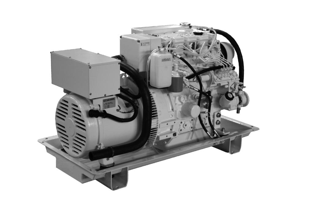
1 PARTS MANUAL P844-3 For Models: L844D, M844W3, M844LW3, NL844W3, NL844LW and M20CRW3
2 CALIFORNIA Proposition 65 Warning: Breathing Diesel engine exhaust and some of its constituents are known to the State of California to cause cancer, birth defects, and other reproductive harm. * Always start and operate the engine in a well-ventilated area. * If in an enclosed area, vent the exhaust to the outside. * Do not modify or tamper with the exhaust system. * Do not idle the engine except as necessary. For more information, go to Northern Lights th Avenue NW Seattle, WA Tel: (206) Fax: (206) Copyright 2018 Northern Lights, Inc. All rights reserved. Northern Lights, and the Northern Lights logo are trademarks of Northern Lights, Inc. Printed in U.S.A. PART NO.: P /18
3 PARTS MANUAL for Models L844D, M844W3, M844LW3, NL844W3, NL844LW3, AND M20CRW3 Please read thoroughly before attempting to use this manual: Table of Contents... 1 Model Designation & Serial Numbers... 2 Reading a Parts Page... 3 Table of Contents GROUP 1 - ENGINE Cylinder Block Assembly Crankshaft Assembly Camshaft & Oil Pump... 8 Cylinder Head Rocker Arm Cover & Assembly GROUP 2 - INTAKE & EXHAUST SYSTEM Air Filter & Housing Air Intake & Filter... 2 Air Filter & Mounting - Industrial... 3 Exhaust Manifold & Muffler - Industrial... 4 GROUP 3 - COOLING Heat Exchanger & Exhaust Manifold Expansion Tank KC & Exhaust Manifold Coolant Pump Raw Water Pump & Mounting... 7 Raw Water Pump Assembly... 8 Radiator & Guard GROUP 4 - FUEL SYSTEM General Arrangement Double Wall Injection Lines & Alarm Tank Governor & Timing Gear Case Fuel Filter & Piping Fuel Line Connection Fuel Injector Fuel Feed Pump Throttle Assembly GROUP 5 - ELECTRICAL SYSTEM 12 & 24 Volt Engine Starter Mounting & Flywheel Housing Alternator & Mounting Wire Harness, Circuit Breaker & Relay Panel. 26 Control Panels Belt Guard Assembly GROUP 6 - GASKET SETS Gasket Sets GROUP 7 - GEAR AND ADAPTER SETS Gear Attaching Parts GROUP 8 - FRAME & MOUNTING Front Engine Mounting... 0 Base Frame Assemblies GROUP 9 - ACCESSORIES GROUP 9 - & OPTIONAL EQUIPMENT PTO... 0 Electric Clutch... 1 Oil Drain Kits Coolant Recovery Tank... 4 Remote Expansion Tank... 5 Low Water Level Switch... 6 Low Coolant Level Switch... 7 Proprietary Information This publication is the sole property of Northern Lights, Inc. It may not be reproduced in whole or part without the expressed written permission of Northern Lights, Inc. Northern Lights, Inc All rights reserved. Litho U.S.A. Publication number: P /17 1
4 MODEL DESIGNATION MODELS INCLUDED This manual covers the parts and components used in: L844D, M844W3, M844LW3, M20CRW3, NL844W3, and NL844LW3. Model Numbers Model numbers give the unit's application, block model, aspiration, and RPM: L - M - NL 844 L W L - Lugger Propulsion engine M - Northern Lights Marine generator set NL - Northern Lights Industrial generator set Model number of engine block Bore Cylinders 84 mm 4 Long stroke engine block Auxiliary generator winding L 844D = M 844W3 = Lugger Propulsion engine with an 844 base engine, Tier III. Northern Lights marine diesel generator set with an 844 engine and a generator with a special winding, Tier III. M 20CRW3 = NL 844LW3 = Northern Lights 20 kw commercial grade marine diesel generator with a generator with a special winding, Tier III. Northern Lights industrial diesel generator set with an 844L engine and a radiator, Tier III. M 844LW3 = Northern Lights marine diesel generator with an 844 engine, long stroke, special winding generator,tier III. Serial Numbers Your set has three serial numbers: 1 an engine number stamped on the block, 2 a generator plate and, 3 a generator set plate. Use the serial number on the generator set plate when ordering parts or in correspondence. The generator set plate is found on the service side of the generator and resembles the drawings below. 2
5 READING A PARTS PAGE IMPORTANT: Before selecting parts, be sure that you are choosing parts from the correct page. Check the model designation at the page top. Do not use this illustration for parts purchasing. 1 ELECTRICAL SYSTEM ALTERNATOR ASSEMBLY: M - NL KEY PART NUMBER QTY. DESCRIPTION SERIALNUMBER Alternator Assembly Flywheel, complete Plate, complete Plate Stator, complete Bearing Nut Spring washer Washer Clamp Screw Screw Collar P844 06/ REFERENCES: 1. Grouping section title. 7. Quantity of parts used. 2. Model designation of equipment that uses parts 8. Description of each component part. listed on this page. 9. Serial number of unit the part fits. 3. Title and description of assembly. 10. Assembly or kit designated by Key 0 or /. 4. Drawing numbers that correspond to key 11. Grouping index number. column numbers for parts identification. 12. Page number within the grouping index. 5. Key column for locating parts shown on drawing. 13. Manual title. 6. Part number. 14. Page publication date. NOTE: a Arrows always point toward the front of the engine. 3
6 GROUP 1 ENGINE Cylinder Block Assembly 844 Marine Application Only Industrial Application Only 844cylblock 1-0
7 revised 4/4/14 GROUP 1 ENGINE Cylinder Block Assembly Cylinder Block Assembly - Marine (includes keys #2-22) Cylinder Block Assembly - Industrial (includes keys #2-22) Expansion Plug 25 mm Expansion Plug 40 mm Plug Plug Plug Idle Gear Shaft Assembly Plug Bush; Standard Bush; Undersize 0.25 mm Bush; Undersize 0.50 mm Bearing Expansion Plug, 45 mm Needle Bearing Needle Bearing Dowel Pin Dowel Pin Dowel Pin Spring Pin Stud M8 x 1.25 x 20 mm Stud M6 x 1.0 x 35 mm Stud M6 x 1.0 x 60 mm Gasket Oil Seal ** Wear Sleeve; Repair Type Drain Cock Filter Joint Oil Filter (Former # ) Tappet Push Rod Relief Valve Assembly O-ring Tube Bushing Oil Pan - Marine up to s/n xxxx-47026c Oil Pan - Marine (former # ) from s/n xxxx-47027c Oil Pan - Industrial Bolt Dipstick Tube O-ring Bolt Dipstick O-ring Oil Pipe Suction Filter Bolt Drain Hose* } up to s/n xxxx-47026c Cap* Seal Washer - Industrial Plug M12 x Industrial - *Marine Application Only - See Oil Drain used from serial number xxxx-47027c **As required 1-1
8 GROUP 1 ENGINE revised Cylinder Block Assembly 844L, M20CRW 844cylblock 1-2
9 revised GROUP 1 ENGINE Cylinder Block Assembly 844L, M20CRW Cylinder Block Assembly - Marine (includes keys #2-22) Cylinder Block Assembly - Industrial (includes keys #2-22) Cylinder Block Assembly - Commercial (includes keys #2-22) Expansion Plug 25 mm Expansion Plug 40 mm Plug Plug Plug Idle Gear Shaft Assembly Plug - Marine & Industrial Plug - Commercial Bush; Standard Bush; Undersize 0.25 mm Bush; Undersize 0.50 mm Bearing Expansion Plug Needle Bearing Needle Bearing Dowel Pin Dowel Pin Dowel Pin Spring Pin Stud M8 x 1.25 x 20 mm Stud M6 x 1.0 x 35 mm Stud M6 x 1.0 x 60 mm Gasket Oil Seal Drain Cock Filter Joint Oil Filter (Former # ) Tappet Push Rod Relief Valve Assembly O-ring Tube Bushing Oil Pan - Commercial (Marine only) up to s/n xxxx-47167c Oil Pan- Marine (former # ) from s/n xxxx-47168c Oil Pan - Industrial Oil Pan with 3/8 NPT & M12 x 1.25 Ports Bolt Dipstick Tube O-ring Bolt Dipstick O-ring Oil Pipe Suction Filter Bolt Oil Drain Hose* Bracket * Capscrew, Hex Head 3/8-16 x 3/4 S/S * Lock Washer 3/8 S/S * Cap* Seal Washer - Industrial Plug M12 x Industrial -. *Marine Application Only - See Oil Drain used from serial number xxxx-47168c 1-3
10 GROUP 1 ENGINE Crankshaft Assembly crankshaft 1-4
11 updated GROUP 1 ENGINE Crankshaft Assembly Crankshaft Assembly (includes keys #2-5) Gear Key Dowel Pin Bearing Holder Assembly (includes keys #7-8) Bolt Dowel Pin Bearing Holder Assembly (includes keys #7-8) Bearing Holder Assembly (includes keys #7-8) Bearing Holder Assembly (includes keys #7-8) Bearing; Standard Bearing; Undersize 0.25 mm Bearing; Undersize 0.50 mm Bearing; Standard Bearing; Undersize 0.25 mm Bearing; Undersize 0.50 mm Thrust Washer Bolt Bolt Ring Kit; Standard Piston Kit; Standard Piston Pin Snap Ring Connecting Rod Assembly (includes keys #22-24) Bushing Connecting Rod Bolt Nut Bearing; Standard Bearing; Undersize 0.25 mm Bearing; Undersize 0.50 mm Thrust Washer Pulley (Marine) Pulley (Industrial) Nut Flywheel Assembly (includes key #30) SAE #7-1/ Ring Gear (109 Teeth) Bolt Drive Belt (see 12V/40A & 24V/24A alternators) Drive Belt (see 12V/ 51A, 24V/ 35A, and 24V/ 40A alternators) - 1-5
12 GROUP 1 ENGINE Crankshaft Assembly 844L & M20CRW3 844crankshaft 1-6
13 updated GROUP 1 ENGINE Crankshaft Assembly 844L & M20CRW Crankshaft Assembly (includes keys #2-4) Gear Key Dowel Pin Bearing Holder Assembly (includes keys #7-8) Bolt Dowel Pin Bearing Holder Assembly (includes keys #7-8) Bearing Holder Assembly (includes keys #7-8) Bearing Holder Assembly (includes keys #7-8) Bearing; Standard Bearing; Undersize 0.25 mm Bearing; Undersize 0.50 mm Bearing; Standard Bearing; Undersize 0.25 mm Bearing; Undersize 0.50 mm Thrust Washer Bolt Bolt Bolt Ring Kit; Standard Piston Kit; Standard (includes key #17) Piston Pin Snap Ring Connecting Rod Assembly (includes keys #22-24) Bushing Connecting Rod Bolt Nut Bearing; Standard Bearing; Undersize 0.25 mm Bearing; Undersize 0.50 mm Thrust Washer Pulley (Marine) Pulley (Industrial) Pulley (Commercial) Nut Flywheel Assembly (includes key #30) SAE #7-1/ Ring Gear (126 Teeth) Bolt Drive Belt (see 12V/40A & 24V/24A alternators) Drive Belt (see 12V/ 51A, 24V/ 35A, and 24V/ 40A alternators) - 1-7
14 added 3/18/11 GROUP 1 ENGINE Kit, Oil Drain and Valve M844 M844L From S/N xxxx-47027c From S/N xxxx-47168c KEY PART NUMBER QTY DESCRIPTION S/N Ball valve, Brass 90 Deg 1/4NPT Male X 1/4NPT Female Male Connector Brass 1/4NPT X 3/8HB Push-On Hose 3/8 ID X 7 Push-On Plug, Hex Head, Brass 1/4NPT Male Connector, Stl. 1/4NPT X 3/8-37T Female Swivel, Brass. 3/8HB X 3/8-37T Push-On - B
15 added 3/18/11 GROUP 1 ENGINE Notes 1-9
16 GROUP 1 ENGINE Camshaft & Oil Pump camshaft Camshaft Assembly (includes keys #2-6) Cam Gear Key Gear Spacer Bearing Slider Plate Bolt Idler Gear Assembly (includes key #12) Thrust Washer Spring Rotor Oil Pump Cover Shim, t= Shim, t= Shim, t= Shim, t= Spring Collar Snap Ring Front Plate (844 & 844L Marine & Propulsion) Front Plate (844 & 844L Industrial) Front Plate (844L Commercial) Gasket Bolt
17 revised GROUP 1 ENGINE Cylinder Head 844 cylhead844 KEY PART NUMBER QTY DESCRIPTION SERIAL # Cylinder Head Assembly (Marine & Propulsion, includes keys #2-12, & 20) Cylinder Head Assembly (Industrial, includes keys #2-12, & 20) Expansion Plug, 18 mm Expansion Plug, 30 mm Expansion Plug, 25 mm Expansion Plug, 10 mm Intake Valve (former # ) Exhaust Valve (former # ) Valve Guide Seal - Intake Spring Retainer Keeper Valve Guide Seal - Exhaust Cap Spacer (Marine) Head Gasket; t = 1.2 mm Head Gasket; t = 1.3 mm Head Bolt Head Bolt Lifting Eye (Marine & Propulsion) Lifting Eye (Industrial) Bolt Valve Seat, Intake Bolt (Marine & Propulsion)
18 revised GROUP 1 ENGINE Cylinder Head 844L cylhead844l KEY PART NUMBER QTY DESCRIPTION SERIAL # Cylinder Head Assembly (Marine, includes keys #2-12, 20, & 22) Cylinder Head Assembly (Industrial, includes keys #2-12, 20, & 22) Expansion Plug, 18 mm Expansion Plug, 30 mm Expansion Plug, 25 mm Expansion Plug, 10 mm Intake Valve (former # ) Exhaust Valve (former # ) Valve Guide Seal - Intake Spring Retainer Keeper Valve Guide Seal - Exhaust Cap Spacer (Marine) Head Gasket; t = 1.1 mm Head Gasket; t = 1.2 mm Head Gasket; t = 1.3 mm Head Bolt Head Bolt Lifting Eye (Marine) Lifting Eye (Industrial) Bolt Valve Seat, Intake Bolt (Marine) Valve Seat, Exhaust
19 revised GROUP 1 ENGINE Cylinder Head M20CRW3 cylhead844l KEY PART NUMBER QTY DESCRIPTION SERIAL # Cylinder Head Assembly (Marine, includes keys #2-12, 20, & 22) Expansion Plug, 18 mm Expansion Plug, 30 mm Expansion Plug, 25 mm Expansion Plug, 10 mm Intake Valve (former # ) Exhaust Valve (former # ) Valve Guide Seal - Intake Spring Retainer Keeper Valve Guide Seal - Exhaust Cap Head Gasket; t = 1.1 mm Head Gasket; t = 1.2 mm Head Gasket; t = 1.3 mm Head Bolt Head Bolt Lifting Eye Bolt Valve Seat, Intake Valve Seat, Exhaust
20 GROUP 1 ENGINE Rocker Arm Assembly rockerarmcover Rocker Arm Assembly (Marine & Propulsion, includes keys 2-7, 16, & 17) Rocker Arm Assembly (Industrial, includes keys 2-7, 16, &17) Rocker Arm Assembly (Commercial, includes keys 2-7, 16, & 17) Rocker Arm - Intake Rocker Arm - Exhaust Screw Nut Rocker Arm Shaft Spring Bolt Stud Bolt Nut Oil Pressure Switch (see Electrical) Oil Pipe (844) Oil Pipe (844L & M20CRW3) Gasket Banjo Bolt Gasket O-ring Shim Banjo Bolt (tapped 1/8 NPT)
21 revised GROUP 1 ENGINE Rocker Arm Cover rockercover Rocker Arm Cover ( L Marine & Propulsion)(former # ) Rocker Arm Cover ( L Industrial) Rocker Arm Cover (844L Commericial) Gasket Baffle Breather Element Screw Gasket Cap Nut Cap O-ring Valve, Breather Bolt Bolt Bolt
22 GROUP 2 INTAKE & EXHAUST SYSTEM Air Filter and Housing L844 A / C Connector, Air Inlet Gasket, Air Intake Mounting Capscrew, Hex Head M6 x 1.0 x 20 mm Wave Washer M6 S/S Hose 1-3/4" ID x 2-1/4" Hose Clamp # Front Cover, Air Filter Housing Plate, Housing Separater Element, Air Filter Screen, Air Filter Retaining Rear Cover, Air Filter Housing Capscrew, Hex Head M6 x 1.0 x 85 mm S/S Wave Washer M6 S/S Bracket, Air Filter Support Capscrew, Hex Head M8 x 1.25 x 16 mm S/S Wave Washer M8 S/S Hose, Air Intake Hose Clamp #28 Extended Band S/S - 2-0
23 revised GROUP 2 INTAKE & EXHAUST SYSTEM Air Filter and Housing M844 & M844L A-10262, A / C Connector, Air Inlet Gasket, Air Intake Mounting Capscrew, Hex Head M6 x 1.0 x 20 mm Wave Washer M6 S/S Hose 1-3/4" ID x 2-1/4" Hose Clamp # Front Cover, Air Filter Housing Plate, Air Filter Baffle (844) Plate, Air Filter Baffle (844L) Element, Air Filter Screen, Air Filter Retaining Rear Cover, Air Filter Housing Capscrew, Hex Head M6 x 1.0 x 85 mm S/S Wave Washer M6 S/S Bracket, Air Filter Support Capscrew, Hex Head M8 x 1.25 x 16 mm S/S Wave Washer M8 S/S Hose, Air Intake (Molded) Hose Clamp # Cushion Clamp # Capscrew, Hex Head M6 x 1.0 x 16 mm S/S Flat Washer, M6 S/S - 2-1
24 GROUP 2 INTAKE & EXHAUST SYSTEM Air Intake & Filter M20CRW3, NL844, & NL844L 844K2airintake Intake Manifold (NL844, NL844L) Intake Manifold (M20CRW3) Gasket Bolt Air Filter (M20CRW3) Hose Clamp - 2-2
25 GROUP 2 INTAKE & EXHAUST SYSTEM Air Filter & Mounting NL844 & 844L 844aircleaner Air Cleaner Assembly (includes keys #13-16) Hose Clamp # Hose Bracket Bracket Lifting Eye Bolt Bolt Bolt Washer Bolt Bolt Housing Element Cover Assembly Valve - 2-3
26 GROUP 2 INTAKE & EXHAUST SYSTEM Exhaust Manifold & Muffler Industrial Muffler Assembly (includes keys #1-4) Exhaust Manifold Muffler Element Gasket Capscrew, Hex Head with Washer M6 x 1.0 x 12 mm Exhaust Pipe Gasket Capscrew, Hex Head with Washer M6 x 1.0 x 25 mm Capscrew, Socket Head M8 x 1.25 x Gasket ** Capscrew, Hex Head M8 x 1.25 x 70 mm ** Stud M8 x 1.25 x 75 mm Lock Washer, Hi-Collar M ** Hex Nut M8 x Exhaust Elbow 1-1/2 NPT, Female Exhaust Elbow, Plain Clamp Flat Washer M Lock Washer M Hex Nut M8 x Capscrew, Hex Head M8 x 1.25 x 65 mm **As required
27 GROUP 2 INTAKE & EXHAUST SYSTEM Notes 2-5
28 GROUP 3 COOLING SYSTEM Heat Exchanger & Exhaust Manifold A-6256, A-6509 / D
29 Revised GROUP 3 COOLING SYSTEM Heat Exchanger & Exhaust Manifold Exhaust Manifold/Expansion Tank Heat Exchanger Element Wet Exhaust Elbow (stainless steel) Wet Exhaust Elbow (cast iron) End Cap Cover Plate Filler Cap (7 PSI) Thermostat (82 C) Gasket Gasket (can use # ) Spring Nameplate, Northern Lights Nameplate, "Lugger" (L844 only) Hose Hose 3/4" ID x 18-1/2" Hose 5/16" ID x 25" Union 3/4 Hose Barb x 3/4 Hose Barb Plug, Socket Head 1/2 NPT Connector, Male 1/2 BSPT x 3/4 Hose Barb Hose Clamp # Hose Clamp # Hose Clamp # ** Hex Head Plug 3/8 NPT Capscrew, Hex Head M8 x 1.25 x 110 mm S/S Capscrew, Hex Head M6 x 1.0 x 110 mm S/S Capscrew, Hex Head M8 x 1.25 x 25 mm S/S Flat Washer M6 S/S Flat Washer M8 S/S Gasket Hose Clamp # Stud M8 x 1.25 x 20 x 25 mm (35 mm OAL) S/S Hex Nut M8 x 1.25 S/S Drain Cock 1/4 NPT Street Elbow, Brass 90 o 1/4 NPT * - * #32 Elbow fitting added to position #31 Drain Cock for side discharge. **As required 3-1
30 Revised GROUP 3 COOLING SYSTEM Expansion Tank & Exhaust Manifold M844 - M844L - M20CRW Keel & Radiator Cooled Applications A-6420, A-6510 / D
31 Revised GROUP 3 COOLING SYSTEM Expansion Tank & Exhaust Manifold M844 - M844L - M20CRW Keel & Radiator Cooled Applications Exhaust Manifold/Expansion Tank End Cap Cover Plate Filler Cap (7 PSI) Thermostat (82 C) Gasket Spring Decal, Northern Lights Drain Cock 1/4 NPT Hose, Overflow 5/16" ID x 25" Hose Clamp #48 (Formerly # NLA) ** Plug, Hex Head 3/8 NPT Capscrew, Hex Head M8 x 1.25 x 110 mm Capscrew, Hex Head M6 x 1.0 x 110 mm Flat Washer M Flat Washer M Gasket Plug, Socket Head 1/8 NPT Hose Male Connector 3/8 NPT x 1/2 HB Hose Clamp # Gasket ** Adapter, Dry Exhaust Straight 1-1/2 NPT (M20CRW only) ** Elbow, Dry Exhaust Heat Shield (used with Straight Adapter - M20CW only) Lagging (used with Dry Elbow) Capscrew, Hex Head M8 x 1.25 x 25mm S/S Lock Washer M8 S/S - ** As Required 3-3
32 GROUP 3 COOLING SYSTEM Coolant Pump Industrial Applications NL844 & 844L P844waterpump 3-4
33 GROUP 3 COOLING SYSTEM Coolant Pump Industrial Applications NL844 & 844L Coolant Pump Assembly (includes keys #2-5) Backing Plate Gasket ** Plug Screw Gasket Bolt Nut Bolt Gasket Thermostat F/ 82 C Thermostat Housing Plug Stud M6 x 1.0 x 45 mm Temperature Switch (221 F/ C) Hose Hose Clamp # Thermostat Cover Gasket Bolt Pulley Cooling Fan Spacer Bolt, M6 x 1.0 x 35 mm - **As required 3-5
34 GROUP 3 COOLING SYSTEM Coolant Pump, Marine & Commercial Revised coolantpump Coolant Pump Assembly (Marine - White) Coolant Pump Assembly (Commercial - Grey) Backing Plate Gasket ** Plug Screw Gasket Bolt Nut Pulley Spacer Bolt - **As required. 3-6
35 Added GROUP 3 COOLING SYSTEM Cooling Fan - Marine Models with Radiator Cooling M844LW3 32B4816D Fan (Blower) 440 mm OD Fan Plate Spacer Capscrew, Socket Head M10 x 1.5 x 20mm Capscrew, Hex Heas Flanged M8 x 1.25 x 20mm Belt ** Spacer Ring - ** As Required 3-7
36 GROUP 3 COOLING SYSTEM Raw Water Pump & Mounting Marine Applications A-4779 / B O-ring Nut M10 x Lock Washer M Fitting 1/2 NPT x 3/4 HB Raw Water Pump (see parts detail) Drive Gear Capscrew, Hex Head M8 x 1.25 x 65 mm Capscrew, Hex Head M8 x 1.25 x 60 mm Lock Washer, Helical M Hex Nut M8 x
37 GROUP 3 COOLING SYSTEM Raw Water Pump Assembly A-3706 / C Raw Water Pump Assembly (includes keys #1-17) Repair Kit (includes keys #3-9 & 11) Housing Shaft Impeller Cam Wear Plate End Cover Bearing Lip Seal Mechanical Seal Spline Seal O-ring Retaining Ring Retaining Ring Washer Pan Head Screw #10-32 x 3/8" Hex Head Screw #10-32 x 3/8" Lock Washer #
38 GROUP 3 COOLING SYSTEM Radiator & Guard Aluminum NL844 & 844L A-6306 / D-2457B 3-10
39 Updated GROUP 3 COOLING SYSTEM Radiator & Guard Aluminum NL844 & 844L Top Panel Side Panel Radiator Support Radiator Assembly, Aluminum (includes keys #20-26) Radiator Assembly (Heresite Coated) Bracket, Upper Radiator Support Spacer, Radiator Support Capscrew, Hex Head M8 x 1.25 x 20 mm Flat Washer M Lock Washer M Capscrew, Hex Head M10 x 1.5 x 20 mm Lock Washer M Capscrew, Hex Head M6 x 1.0 x 16 mm Lock Washer M Flat Washer M Capscrew, Hex Head M6 x 1.0 x 20 mm Hex Nut M6 x Hose, Radiator Inlet Hose, Radiator Outlet Hose Clamp # Radiator Cap Bolt Shroud with Fan Guard Drain Cock O-ring Hose Label Northern Lights (not shown) ** Grille ** Air Duct Adapter (optional - not shown) Bracket, Radiator Mounting - ** As required 3-11
40 GROUP 4 FUEL SYSTEM General Arrangement L844 injectors
41 Revised GROUP 4 FUEL SYSTEM General Arrangement L Injection Pump Assembly Shim Set (formerly # ) Nut Bolt Gasket Fuel Injector (see parts detail page) Return Line Injection Line # Injection Line # Injection Line # Injection Line # Clamp Bolt Nut Glow Plug 12 Volt* Glow Plug 24 Volt* Connector Gasket Feed Pump Assembly (see parts detail page) Bolt Stop Solenoid - 12 Volt (Standard Ground)* Stop Solenoid - 12 Volt (Isolated Ground)* Stop Solenoid - 24 Volt (Isolated Ground)* Screw Seal Washer Seal Washer Wire Harness Spring Washer Nut - *Note: See Electrical System 4-1
42 GROUP 4 FUEL SYSTEM General Arrangement M - NL844 injectors
43 revised GROUP 4 FUEL SYSTEM General Arrangement M - NL Injection Pump Assembly Shim Set (formerly # ) Nut Bolt Gasket Fuel Injector (see parts detail page) Return Line Injection Line # Injection Line # Injection Line # Injection Line # Clamp Bolt Nut Glow Plug 12 Volt* Glow Plug 24 Volt* Connector Gasket Feed Pump Assembly (see parts detail page) Bolt Stop Solenoid - 12 Volt (Standard Ground)* Stop Solenoid - 12 Volt (Isolated Ground)* Stop Solenoid - 24 Volt (Isolated Ground)* Screw Seal Washer Seal Washer Wire Harness Spring Washer Nut - *Note See Electrical System 4-3
44 GROUP 4 FUEL SYSTEM General Arrangement M - NL844L injectors
45 revised GROUP 4 FUEL SYSTEM General Arrangement M - NL844L Injection Pump Assembly Shim Set (formerly # ) Nut Bolt Gasket Fuel Injector (see parts detail page) Return Line Injection Line # Injection Line # Injection Line # Injection Line # Clamp Bolt Nut Glow Plug 12 Volt* Glow Plug 24 Volt* Connector Gasket Feed Pump Assembly (see parts detail page) Bolt Stop Solenoid - 12 Volt (Standard Ground)* Stop Solenoid - 12 Volt (Isolated Ground)* Stop Solenoid - 24 Volt (Isolated Ground)* Screw Seal Washer Seal Washer Wire Harness Spring Washer Nut - *Note: See Electrical System 4-5
46 GROUP 4 FUEL SYSTEM General Arrangement M20CRW3 M20CRWfuelsystem 4-6
47 revised GROUP 4 FUEL SYSTEM General Arrangement M20CRW Injection Pump Assembly Shim Nut Bolt Gasket Fuel Injector (see parts detail page) Return Line Injection Line # Injection Line # Injection Line # Injection Line # Clamp Bolt Nut Glow Plug 12 Volt* Connector Gasket Feed Pump Assembly (see parts detail page) Bolt Stop Solenoid - 12 Volt (Standard Ground)* Screw Seal Washer Seal Washer Wire Harness Nut Bolt Washer - *Note: See Electrical System 4-7
48 Added GROUP 4 FUEL SYSTEM Double Wall Injecton Lines Alarm Tank M844LW3 4-8
49 Added & revised Double Wall Injecton Lines Alarm Tank GROUP 4 FUEL SYSTEM M844LW Injection Line #1 Double Wall (Marked #1) Injection Line #2 Double Wall (Marked #2) Injection Line #3 Double Wall (Marked #3) Injection Line #4 Double Wall (Marked #4) Manifold, Injection Lines Leak-Off Banjo Bolt O-Ring Sealing Washer, Bonded 1/4 BSPP Sealing Washer 1/8 BSPP Male Connector, Steel, 1/4 BSPP x 8mm COMP Tube, Leak-Off Manifold Outlet Compression Union, Steel 8mm Hose Assembly 1/4 ID x 9-1/2 S/S - TFE Alarm Tank Assembly Clamp Assembly, 2-Lines Clamp Assembly, 3-Lines Bracket Capscrew, Hex Head M14 x 1.5 x 30mm S/S Lock Washer, Helical M14 S/S Flat Washer M14 S/S Capscrew, Hex Head M8 x 1.25 x 30mm S/S Flat Washer M8 S/S Hex Nut, Nylock M8 x 1.25 S/S - 4-9
50 GROUP 4 FUEL SYSTEM Governor & Timing Gear Case timinggear
51 revised GROUP 4 FUEL SYSTEM Governor & Timing Gear Case Timing Gear Case Complete (Marine,includes key #2) Timing Gear Case Complete (Industrial, includes key #2) Timing Gear Case Complete (Commercial, includes key #2) Spring Pin Gasket Oil Seal Governor Lever Assembly (includes keys #7 - #10) Tension Lever Snap Ring Washer Snap Pin Governor Spring Arm (Marine & Industrial) Arm (Commercial) O-ring Governor Lever Bolt Nut Shaft O-ring Snap Ring Bracket Bolt Bolt Bolt Bolt Bolt Bolt Start Spring Cover (Marine) Cover (Industrial) Cover (Commercial) Gasket (former # ) ** Hex Nut O-ring Spring Oil Fill Elbow (Marine & Commercial) O-ring (Marine & Commercial) Cap (Marine & Commercial) ** Bolt (Marine & Commercial) Bolt (Industrial) - *No longer available separately. **As required 4-11
52 GROUP 4 FUEL SYSTEM Fuel Filter & Piping 844fuelfiltercomm 4-12
53 GROUP 4 FUEL SYSTEM Fuel Filter & Piping Fuel Filter Assembly (includes keys #2-5) Fuel Filter Cartridge Gasket Banjo Bolt Plug Bracket (Marine) Bracket (Industrial) Bracket (Commercial) Bracket (Marine) Bracket (Industrial) Bracket (Commercial) Bolt Nut Spring Washer Nut Bolt (Marine & Commercial) Bolt (Industrial) Pipe (L-M-NL844) Pipe (L-M-NL844L & Commercial) Pipe Pipe Bolt Washer Gasket Banjo Bolt Banjo Bolt Gasket Banjo Bolt Gasket Washer
54 GROUP 4 FUEL SYSTEM Fuel Line Connection L844 USCG A-1 - SAE J ISO 7840 Updated A-11854/ B Fuel Manifold 1/4 NPT Capscrew, Hex Head 3/8-16 x 1-1/ Lock Washer, 3/ Male Elbow 45 0 Brass 1/4 NPT x 1/4-45T Hose Assembly 1/4 I.D. x 8 1/4 FMS Elbow 90 0 Swivel Steel 1/4-37T Male Connector Steel 1/4-37T x M8 x Sealing Washer, Bonded M Hose Assembly 1/4 I.D. x 14 1/4 FMS
55 added 3/22/11 GROUP 4 FUEL SYSTEM USCG A-1 SAE J1527 ISO 7840 Fuel Lines M844 up to s/n xxxx-47026c M844L up to s/n xxxx-47167c NL844 & NL844L All A-11855/ B Fuel Manifold 1/4 NPT Capscrew, Hex Head M6 x 1.0 x 16 mm S/S Lock Washer, Helical M6 S/S Plug, Hex Head Brass 1/4 NPT Male Elbow 90, Brass 1/4 NPT x 5/16-45T Male Elbow 90 0, Brass 1/4 NPT x 1/4-45T Hose Assembly 1/4" ID x Hose Assembly 1/4" ID x
56 GROUP 4 FUEL SYSTEM USCG A-1 SAE J1942 ABS Fuel Lines M844 from s/n xxxx-47027c M844 from s/n xxxx-47168c added 3/22/11 A-6684/ B Fuel Manifold 1/4 NPT Capscrew, Hex Head M6 x 1.0 x 16 mm S/S Lock Washer, Helical M6 S/S Plug, Hex Head Brass 1/4 NPT Male Elbow 90, Brass 1/4 NPT x 5/16-45T Male Elbow 90 0, Brass 1/4 NPT x 1/4-45T Hose Assembly 1/4" ID x Hose Assembly 1/4" ID x
57 updated GROUP 4 FUEL SYSTEM USCG A-1 SAE J1527 ISO 7840 Fuel Lines M844 from s/n xxxx-47027c M844L from s/n xxxx-47168c B-9827 Key Part Number Qty Description Serial Number Plug, Hex Head Brass 1/4 NPT Male Elbow, 45, Steel 1/4NPT X 5/16-37T Male Elbow, 45, Steel 1/4NPT X 1/4-37T Hose Assembly 1/4 ID x Hose Assembly 3/16 ID x
58 GROUP 4 FUEL SYSTEM USCG A-1 SAE J1942 ABS Fuel Lines M844 from s/n xxxx-47027c M844L from s/n xxxx-47168c revised 3/23/11 B-9827 Key Part Number Qty Description Serial Number Plug, Hex Head Brass 1/4 NPT Male Elbow, 45, Steel 1/4NPT X 5/16-37T Male Elbow, 45, Steel 1/4NPT X 1/4-37T Hose Assembly 1/4 ID x Hose Assembly 3/16 ID x
59 GROUP 4 FUEL SYSTEM Fuel Injector injector Injector Assembly (includes keys #1-8) Nut Gasket Shim Spring Spring seat Spacer Nozzle Nut
60 GROUP 4 FUEL SYSTEM Fuel Feed Pump feedpump Feed Pump Assembly (includes keys #1-15) Housing* Spring Piston Spring Diaphragm Pin Lever O-ring Spring Guide* Gasket Cap* Screw Gasket Banjo Bolt - *No longer available separately. 4-20
61 Updated GROUP 4 FUEL SYSTEM Throttle Assembly A-10414/ B Throttle Bracket Cable Clamp Clamp Shim Capscrew, Hex Head M5 x 0.8 x 14 mm Lock Washer, Helical M Capscrew, Hex Head M6 x 1.0 x 16 mm Lock Washer, Helical M Throttle Pivot Flat Washer, M8 S/S Cotter Pin, Brass 5/64 x Clevis Pin, S/S
62 GROUP 5 ELECTRICAL SYSTEM Engine Electrical 12 Volt Standard Ground Propulsion Units A / C
63 GROUP 5 ELECTRICAL SYSTEM Engine Wire Harness Oil Pressure Sender 0-80 PSI, Standard Ground Oil Pressure Switch, Standard Ground 14.2 PSI Temperature Sender 250 F, Standard Ground Temperature Switch 95 C Bracket, Circuit Breaker and Relays Capscrew, M14 x 1.5 x 30 S/S Flat Washer, M14 S/S Capscrew, Hex Head M6 x 1.0 x 20 mm Flat Washer M Hex Nut M6 x Relay 12 Volt 50 Amp Cover, Circuit Breaker and Relays Machine Screw, BH Slotted #10-32 x 3/8" S/S Flat Washer #10 S/S Magnetic Pick-up, M18 x 1.5 x 58 mm ' Wire Harness Extension (not shown) Solenoid 12 VDC 65 Amp Bracket, Relay Mounting Capscrew, Hex Head M6 x 1.0 x 16 mm Flat Washer M Hex Nut, Nylock M6 x Capscrew, Hex Head M14 x 1.5 x 30 mm S/S Lock Washer, M14 S/S Control Panel 12 Volt (not shown, see parts detail) Starter 12 Volt (see parts detail) Capscrew, Hex Head M10 x 1.5 x 30 mm Wave Washer M Stop Solenoid 12 Volt Glow Plug 12 Volt Alternator 12V/ 40 Amp Street Elbow, 90 1/8 NPT Capscrew, M6 x 1.0 x 16 mm S/S Lock Washer Flat Washer M Exhaust Temperature Switch 205 F ** Harness Assembly, High Exhaust Temperature (not shown) Banjo Bolt - **As required Updated 3/18/11 Engine Electrical 12 Volt Standard Ground Propulsion Units 5-1
64 GROUP 5 ELECTRICAL SYSTEM Engine Electrical 24 Volt Standard Ground Propulsion Units A / C
65 Updated 3/18/11 GROUP 5 ELECTRICAL SYSTEM Engine Electrical 24 Volt Standard Ground Engine Wire Harness Oil Pressure Sender 0-80 PSI, Standard Ground Oil Pressure Switch, Standard Ground 14.2 PSI Temperature Sender 250 F, Standard Ground Temperature Switch 95 C Bracket, Circuit Breaker and Relays Capscrew, M14 x 1.5 x 30 S/S Flat Washer, M14 S/S Capscrew, Hex Head M6 x 1.0 x 20 mm Flat Washer M Hex Nut M6 x Relay 24 Volt 20 Amp Cover, Circuit Breaker and Relays Machine Screw, BH Slotted #10-32 x 3/8" S/S Flat Washer #10 S/S Magnetic Pick-up, M18 x 1.5 x 58 mm ' Wire Harness Extension (not shown) Solenoid 24 VDC 65 Amp Bracket, Relay Mounting Capscrew, Hex Head M6 x 1.0 x 16 mm Flat Washer M Hex Nut, Nylock M6 x Capscrew, Hex Head M14 x 1.5 x 30 mm S/S Lock Washer, Helical M14 S/S Main Instrument Panel 24 Volt (not shown - see parts detail) Starter 24 Volt (see parts detail) Capscrew, Hex Head M10 x 1.5 x 30 mm Wave Washer M Stop Solenoid 24 Volt Glow Plug 24 Volt Alternator 24V/ 40 Amp Street Elbow, 90 1/8 NPT Capscrew, M6 x 1.0 x 16 mm S/S Lock Washer Flat Washer M Exhaust Temperature Switch, 205 F ** Harness Assembly, High Exhaust Temperature (not shown) Banjo Bolt - **As required Propulsion Units 5-3
66 Updated GROUP 5 ELECTRICAL SYSTEM Engine Electrical 12 Volt Standard Ground Marine Units A-6258 / C-2490AA 5-4
67 Updated 4/1/16 GROUP 5 ELECTRICAL SYSTEM Engine Electrical 12 Volt Standard Ground Temperature Sender 250 F 3/8 NPT Dual Station Temperature Sender 250 F (former # ) Bushing, Brass 3/8NPT x 1/8 NPT (for sender ) Temperature Switch 95 C M16 x Oil Pressure Switch 1/8 NPT Oil Pressure Sender 1/8 NPT Dual Station Oil Pressure Sender 1/8 NPT Relay, 12 Volt SPDT Terminal Retainer Relay Base Circuit Breaker, DC 15 Amp - Snap-In Type Circuit Breaker DC 15 Amp - Screw Mount Type Control Panel, S1-B (see detail) Engine Wire Harness - Round Merc Plug Connector Diode, 6 Amp 50 Volt PIV Wire Harness Extension 20 (not shown) Grommet Machine Screw #10-32 x 3/8 s/s Flat Washer # Hex Nut, Nylock # Hex Nut, M8 x Lock Washer M Hex Nut, M5 x Lock Washer M Stop Solenoid 12 Volt (see also Fuel System) Alternator 12 Volt 40 AMP Banjo Bolt M8 x 1.25 x 18mm (tapped 1/8 NPT) Oil Line Starter 12 Volt (see mounting detail) Street 90 o Steel 1/8 NPT x 1/8 NPT (not shown) - Marine Units 5-5
68 Added 4/16 GROUP 5 ELECTRICAL SYSTEM Engine Electrical 12 Volt Standard Ground B+ System Marine Units A-6258 / C-2490AA 5-6
69 Added 4/16 GROUP 5 ELECTRICAL SYSTEM Engine Electrical 12 Volt Standard Ground B+ System Marine Units Temperature Sender 250 F 3/8 NPT Dual Station Temperature Sender 250 F 1/8 NPT Bushing, Brass 3/8NPT x 1/8 NPT (for sender ) Temperature Switch 95 C M16 x Oil Pressure Switch 1/8 NPT Oil Pressure Sender 1/8 NPT Dual Station Oil Pressure Sender 1/8 NPT Relay, 12 Volt SPDT Terminal Retainer Relay Base Circuit Breaker DC 10 Amp - Screw Mount Type Control Panel, S1-B (see detail) Engine Wire Harness - Square Deutsch Plug Connector Diode, 1 Amp 200 Volt Wire Harness Extension 20 (not shown) Grommet Machine Screw #10-32 x 3/8 s/s Flat Washer # Hex Nut, Nylock # Hex Nut, M8 x Lock Washer M Hex Nut, M5 x Lock Washer M Stop Solenoid 12 Volt (see also Fuel System) Alternator 12 Volt 40 AMP Banjo Bolt M8 x 1.25 x 18mm (tapped 1/8 NPT) Oil Line Starter 12 Volt (see mounting detail) Street 90 o Steel 1/8 NPT x 1/8 NPT (not shown) - 5-7
70 Updated GROUP 5 ELECTRICAL SYSTEM Engine Electrical 12 Volt Isolated Ground Marine Units A-6398, A-6402 / C-2490C 5-8
71 Updated 4/1/16 GROUP 5 ELECTRICAL SYSTEM Engine Electrical 12 Volt Isolated Ground Temperature Sender 250 F 3/8 NPT Dual Station Temperature Sender 250 F (former # ) * Temperature Switch 95 C M16 x Oil Pressure Switch 1/8 NPT Oil Pressure Sender 1/8 NPT Dual Station Oil Pressure Sender 1/8 NPT Relay, 12 Volt SPDT Relay Base Terminal Retainer Circuit Breaker, 15 Amp - Snap-In Type Circuit Breaker, 15 AMP - Screw Mount Type Control Panel, S1-B (see detail) Engine Wire Harness - Round Merc Plug Connector Ground Harness Addition Diode, 6 Amp 50 Volt PIV Wire Harness Extension 20 (not shown) Grommet Machine Screw #10-32 x 3/8 S/S Flat Washer # Hex Nut, Nylock # Hex Nut, M8 x Lock Washer M Hex Nut, M5 x Lock Washer M Stop Solenoid 12 Volt (see also Fuel System) Alternator 12 Volt 40 AMP Banjo Bolt M8 x 1.25 x 18mm (Tapped 1/8 NPT) Oil Line Starter 12 Volt (see mounting detail) Branch Tee Steel 1/8 NPT x 1/8 NPT (not shown) Plug 1/8BSPT Bushing 3/8 NPT x 1/4 NPT * - * Bushing required with replacement sender Marine Units 5-9
72 Added 4/1/16 GROUP 5 ELECTRICAL SYSTEM Engine Electrical 12 Volt Isolated Ground B+ System Marine Units A-6398, A-6402 / C-2490C 5-10
73 Added 4/1/16 GROUP 5 ELECTRICAL SYSTEM Engine Electrical 12 Volt Isolated Ground B+ System Marine Units Temperature Sender 250 F 3/8 NPT Dual Station Temperature Sender 250 F 1/4 NPT * Temperature Switch 95 C M16 x Oil Pressure Switch 1/8 NPT Oil Pressure Sender 1/8 NPT Dual Station Oil Pressure Sender 1/8 NPT Relay, 12 Volt SPDT Relay Base Terminal Retainer Circuit Breaker, 10 AMP - Screw Mount Type Control Panel, S1-B (see detail) Engine Wire Harness - Square Deutsch Plug Connector Ground Harness Addition Diode, 1 Amp 200 Volt Wire Harness Extension 20 (not shown) Grommet Machine Screw #10-32 x 3/8 S/S Flat Washer # Hex Nut, Nylock # Hex Nut, M8 x Lock Washer M Hex Nut, M5 x Lock Washer M Stop Solenoid 12 Volt (see also Fuel System) Alternator 12 Volt 40 AMP Banjo Bolt M8 x 1.25 x 18mm (Tapped 1/8 NPT) Oil Line Starter 12 Volt (see mounting detail) Branch Tee Steel 1/8 NPT x 1/8 NPT (not shown) Plug 1/8BSPT Bushing 3/8 NPT x 1/4 NPT * - * Bushing required with sender
74 Updated GROUP 5 ELECTRICAL SYSTEM Engine Electrical 24 Volt Standard Ground Marine Units A-6258 / C-2490AA 5-12
75 Updated GROUP 5 ELECTRICAL SYSTEM Engine Electrical 24 Volt Standard Ground Marine Units Temperature Sender 250 F 3.8 NPT Dual Station Temperature Sender 250 F (former # ) Bushing, Brass 3/8NPT x 1/8 NPT (for sender ) Temperature Switch 95 C M16 x Oil Pressure Switch 1/8 NPT Oil Pressure Sender 1/8 NPT Dual Station Oil Pressure Sender 1/8 NPT Relay, 24 Volt SPDT Relay Base Terminal Retainer Circuit Breaker, 15 Amp - Snap-In Type Circuit Breaker 15 Amp - Screw Mount Type Control Panel, S1-B (see detail) Engine Wire Harness - Round Merc Plug Connector Diode, 6 Amp 50 Volt PIV Wire Harness Extension 20' (not shown) Grommet Machine Screw #10-32 x 3/8" s/s Flat Washer # Hex Nut, Nylock # Hex Nut, M8 x Lock Washer M Hex Nut, M5 x Lock Washer M Stop Solenoid 24 Volt (see also Fuel System) Alternator 24 Volt 40 AMP up to S/N xxxx-47026c (844) 1 Alternator 24 Volt 40 AMP up to S/N xxxx-47167c (844L) Alternator 24 Volt 25 AMP from S/N xxxx-47027c (844) 1 Alternator 24 Volt 25 AMP from S/N xxxx-47168c (844L) Banjo Bolt M8 x 1.25 x 18mm (Tapped 1/8 NPT) Oil Line Starter 24 Volt (see mounting detail) (former # ) Street 90 o Steel 1/8 NPT x 1/8 NPT (not shown)
76 Added GROUP 5 ELECTRICAL SYSTEM Engine Electrical 24 Volt Standard Ground B+ System Marine Units A-6258 / C-2490AA 5-14
77 revised GROUP 5 ELECTRICAL SYSTEM Engine Electrical 24 Volt Standard Ground B+ System Marine Units Temperature Sender 250 F 3.8 NPT Dual Station Temperature Sender 250 F 1/4 NPT Bushing, Brass 3/8NPT x 1/8 NPT (for sender ) Temperature Switch 95 C M16 x Oil Pressure Switch 1/8 NPT Oil Pressure Sender 1/8 NPT Dual Station Oil Pressure Sender 1/8 NPT Relay, 24 Volt SPDT Relay Base Terminal Retainer Circuit Breaker 10 Amp - Screw Mount Type Control Panel, S1-B (see detail) Engine Wire Harness - Square Deutsch Plug Connector Diode, 1 Amp 200 Volt Wire Harness Extension 20' (not shown) Grommet Machine Screw #10-32 x 3/8" s/s Flat Washer # Hex Nut, Nylock # Hex Nut, M8 x Lock Washer M Hex Nut, M5 x Lock Washer M Stop Solenoid 24 Volt (see also Fuel System) Alternator 24 Volt 25 AMP Banjo Bolt M8 x 1.25 x 18mm (Tapped 1/8 NPT) Oil Line Starter 24 Volt (see mounting detail) Street 90 o Steel 1/8 NPT x 1/8 NPT (not shown)
78 Updated GROUP 5 ELECTRICAL SYSTEM Engine Electrical 24 Volt Isolated Ground Marine Units A-6398, A-6402 / C-2490C 5-16
79 Updated GROUP 5 ELECTRICAL SYSTEM Engine Electrical 24 Volt Isolated Ground Marine Units Temperature Sender 250 F 3/8 NPT Dual Station Temperature Sender 250 F 1/4 NPT (former # )* Temperature Switch 95 C M16 x Oil Pressure Switch 1/8 NPT Oil Pressure Sender 1/8 NPT Dual Station Oil Pressure Sender 1/8 NPT Relay, 24 Volt SPDT Relay Base Terminal Retainer Circuit Breaker, 15 Amp - Snap-In Type Circuit Breaker 15 Amp - Screw Mount Type Control Panel, S1-B (see detail) Engine Wire Harness - Round Merc Plug Connector Ground Harness Addition Diode, 6 Amp 50 Volt PIV Wire Harness Extension 20' (not shown) Grommet Machine Screw #10-32 x 3/8" S/S Flat Washer # Hex Nut, Nylock # Hex Nut, M8 x Lock Washer M Hex Nut, M5 x Lock Washer M Stop Solenoid 24 Volt (see also Fuel System) Alternator 24 Volt 35 AMP up to S/N xxxx-47026c (844) 1 Alternator 24 Volt 35 AMP up to S/N xxxx-47167c (844L) Alternator 24 Volt 25 AMP from S/N xxxx-47027c (844) 1 Alternator 24 Volt 25 AMP from S/N xxxx-47168c (844L) Banjo Bolt M8 x 1.5 x 18mm (Tapped 1/8 NPT) Oil Line Starter 24 Volt (see mounting detail) (former # ) Branch Tee Steel 1/8 NPT x 1/8 NPT (not shown) Plug 1/8BSPT - * Bushing required with replacement sender
80 Added GROUP 5 ELECTRICAL SYSTEM Engine Electrical 24 Volt Isolated Ground B+ System Marine Units A-6398, A-6402 / C-2490C 5-18
81 revised GROUP 5 ELECTRICAL SYSTEM Engine Electrical 24 Volt Isolated Ground B+ System Marine Units Temperature Sender 250 F 3/8 NPT Dual Station Temperature Sender 250 F 1/4 NPT * Temperature Switch 95 C M16 x Oil Pressure Switch 1/8 NPT Oil Pressure Sender 1/8 NPT Dual Station Oil Pressure Sender 1/8 NPT Relay, 24 Volt SPDT Relay Base Terminal Retainer Circuit Breaker - 10 Amp, Screw Mount Type Control Panel, S1-B (see detail) Engine Wire Harness - Square Deutsch Plug Connector Ground Harness Addition Diode, 1 Amp 200 Volt Wire Harness Extension 20' (not shown) Grommet Machine Screw #10-32 x 3/8" S/S Flat Washer # Hex Nut, Nylock # Hex Nut, M8 x Lock Washer M Hex Nut, M5 x Lock Washer M Stop Solenoid 24 Volt (see also Fuel System) Alternator 24 Volt 25 AMP Banjo Bolt M8 x 1.5 x 18mm (Tapped 1/8 NPT) Oil Line Starter 24 Volt (see mounting detail) Branch Tee Steel 1/8 NPT x 1/8 NPT (not shown) Plug 1/8BSPT - * Bushing required with replacement sender
82 GROUP 5 ELECTRICAL SYSTEM Engine Electrical - 12 Volt Standard Ground Industrial Units A-4786/ C-2490Bnl 5-20
83 Updated GROUP 5 ELECTRICAL SYSTEM Engine Electrical - 12 Volt Standard Ground Industrial Units Temperature Sender, F Single Station 3/8 NPT Temperature Switch 221 F/ 105 C Oil Pressure Sender 0-80 PSI, Single Station 1/8 NPT Oil Pressure Switch Relay, 12 Volt SPDT Relay Base Circuit Breaker 15 Amp - Snap-In Type Circuit Breaker 15 Amp - Screw Mount Type Terminal Retainer Engine Wire Harness (includes key #10) Diode, 6 Amp 50 Volt Wire Harness Extension 20' (not shown) Grommet Machine Screw #10-32 x 3/8" Stainless Steel Flat Washer # Hex Nut, # Hex Nut, M8 x Lock Washer M Hex Nut, M5 x Lock Washer M Street Elbow 90 0, 1/8 NPT Steel Alternator 12 Volt (see parts detail) Oil Line Banjo Bolt (Tapped 1/8 NPT Female) Starter 12 Volt (see parts detail) Fuel Solenoid 12 Volt
84 GROUP 5 ELECTRICAL SYSTEM Updated Starter & Flywheel Housing L - M - NL844 flywheel Flywheel Housing - Marine SAE # Flywheel Housing - Industrial SAE # Bolt Starter - 12 Volt - Standard Ground (marked M001T66081)* Starter - 12 Volt - Isolated Ground Starter - 24 Volt - Standard Ground (Former # ) Starter - 24 Volt - Isolated Ground (Former # ) Capscrew, Hex Head M10 x 1.5 x 25 mm (12 Volt Starters) Capscrew, Hex Head M10 x 1.5 x 30 mm (24 Volt Starters) Bracket } Lock Washer for marine and propulsion - units only Bolt - *See parts detail. 5-22
85 Updated GROUP 5 ELECTRICAL SYSTEM Starter & Flywheel Housing M844DW - M844LW - M20CRW - NL844L M844DW - M844LW - M20CRW - NL844L flywheel844l KEY PART NUMBER QTY DESCRIPTION SERIAL # Flywheel Housing - Marine SAE # Flywheel Housing - Industrial SAE # Flywheel Housing - Commercial SAE # Back Plate - Marine Back Plate - Industrial Back Plate - Commercial Bolt Bolt Bolt Bolt Nut Spring Washer Bolt Starter - 12 Volt - Standard Ground (marked M001T66081) Starter - 12 Volt - Isolated Ground Starter - 24 Volt - Standard Ground (former # ) Starter - 24 Volt - Isolated Ground (former # ) Capscrew, Hex Head M10 x 1.5 x 25 mm (12 Volt Starters) Capscrew, Hex Head M10 x 1.5 x 30 mm (24 Volt Starters) Bracket (Marine only) Bolt (Marine only)
86 page updated GROUP 5 ELECTRICAL SYSTEM Small Frame Alternators & Mounting Standard & Isolated Ground 844alt Alternator 12 Volt/ 40 Amp Standard Ground (see parts detail) Alternator 12 Volt/ 40 Amp Isolated Ground Alternator 24 Volt/ 25 Amp Standard Ground from s/n xxxx-47027c (M844) Alternator 24 Volt/ 25 Amp Isolated Ground } from s/n xxxx-47168c (M844L) Tensioner Bolt Washer Bracket Bolt Bolt Nut Drive Belt L844D - M-NL844W Drive Belt M844DW - M-NL844LW - M20CRW Bolt - } 5-24
87 page updated GROUP 5 ELECTRICAL SYSTEM Medium Frame Alternator Options 12V/51 Amp & 24V/35 & 40 Amp A-7631, A-7632, A-7633, A-7634, A-7635, A-7636 & D Alternator 12 Volt/51 Amp Isolated Ground Alternator 24 Volt/40 Amp Standard Ground Alternator 24 Volt/35 Amp Isolated Ground Pulley 1-A x 2-1/2" x 5/8" ID Bracket, Alternator Mounting Capscrew, Hex Head M8 x 1.25 x 20 mm Lock Washer, Helical M Capscrew, Hex Head 1/2-13 x 2-3/4" Spacer ** Flat Washer, 1/2 SAE Hex Nut, Nylock 1/ Tensioning Arm (used with 24 Volt/35 Amp Alternator) Tensioning Arm (used with 12 Volt/51 Amp & 24 Volt/40 Amp Alternators) Capscrew, Hex Head 5/16-18 x 1" Stud Washer 5/ Lock Washer, Helical 5/ Diode Harness Addition Drive Belt (844) Drive Belt (844L & M20CR, CRW) D.C. Voltage Regulator, 12V, Adjustable Wire Harness 36" Machine Screw #10-32 x 3/4" s/s }12 Volt / 51 Amp Flat Washer #10 s/s Alternator Only Hex Nut, Nylock #10 s/s - **As required 5-25
88 GROUP 5 ELECTRICAL SYSTEM page updated Wire Harness, Circuit Breaker, & Relay Panel L844 B Wire Harness Assembly (includes keys #1-6) Bracket AMP Circuit Breaker Relay Base Terminal Retainer (not shown) Machine Screw, Flathead Countersunk #10-32 x 3/8" Hex Nut, # Machine Screw, Flathead Countersunk #10-32 x 1" Relay, 12 Volt SPST Relay, 24 Volt SPST
89 page updated GROUP 5 ELECTRICAL SYSTEM Main Instrument Panel 12 Volt with VDO Oceanline Guages L844 A-11651, A / B changed Main Instrument Panel, 12 Volt (includes all keys) Plate, Main Instrument Panel Tachometer RPM 12/24 Volt *Replaced by Tachometer RPM Voltmeter 8-16 VDC Temperature Gauge F 12 Volt Oil Pressure Gauge 0-80 PSI 12 Volt Alarm Horn 12/ 24 Volt Hourmeter 12/ 24 Volt Lamp Holder, Amber Lens Bulb, Clear 12 Volt Key Switch Toggle Switch, SPST maintained Diode 6 Amp 50 Volt (not shown) Fuse Holder, In-line 15 Amp 32 Volt Fuse 7-1/2 Amp 240 VAC/DC Plug, 5/8 O.D., Black Nylon Wire Harness O-ring Bulb Diffuser, Red (use with Tachometer ) Bulb Diffuser, Red (use with Tachometer ) Self-tapping Screw Label, Panel Electrical Load Warning (not shown) Label, 12 Volt (not shown) Bulb, Clear 12 Volt (use with Tachometer ) Bulb, Clear 12 Volt (use with Tachometer ) Bulb, Red 12 Volt
90 page updated GROUP 5 ELECTRICAL SYSTEM Main Instrument Panel 24 Volt with VDO Oceanline Guages L844 A-11651, A / B changed Main Instrument Panel, 24 Volt (includes all keys) Plate, Main Instrument Panel Tachometer RPM 12/24 Volt *Replaced by Tachometer RPM Voltmeter 8-16 VDC Temperature Gauge F 24 Volt Oil Pressure Gauge 0-80 PSI 24 Volt Alarm Horn 12/ 24 Volt Hourmeter 12/ 24 Volt Lamp Holder, Amber Lens Bulb, Clear 24 Volt Key Switch Toggle Switch, SPST maintained Diode 6 Amp 50 Volt (not shown) Fuse Holder, In-line 15 Amp 32 Volt Fuse 7-1/2 Amp 240 VAC/DC Plug, 5/8 O.D., Black Nylon Wire Harness O-ring Bulb Diffuser, Red (use with Tachometer ) Bulb Diffuser, Red (use with Tachometer ) Self-tapping Screw Label, Panel Electrical Load Warning (not shown) Label, 24 Volt (not shown) Bulb, Clear 24 Volt (use with Tachometer ) Bulb, Clear 24 Volt (use with Tachometer ) Bulb, Red 24 Volt
91 page updated GROUP 5 ELECTRICAL SYSTEM Main Instrument Panel 12 Volt with SAE Black Bezel Gauges L844 B changed Main Instrument Panel, 12 Volt (includes all keys) Plate, Main Instrument Panel Tachometer RPM 12/24 Volt Voltmeter 8-16 VDC Temperature Gauge F 12 Volt Oil Pressure Gauge 0-80 PSI 12 Volt Alarm Horn 12/ 24 Volt Hourmeter 12/ 24 Volt Lamp Holder, Amber Lens Bulb, Clear 12 Volt Key Switch Toggle Switch, SPST maintained Diode 6 Amp 50 Volt (not shown) Fuse Holder, In-line 15 Amp 32 Volt Fuse 7-1/2 Amp 240 VAC/DC Plug, 5/8 O.D., Black Nylon Wire Harness O-ring O-Ring Self-tapping Screw Label, Panel Electrical Load Warning (not shown) Bulb Diffuser, Red Label, 12 Volt (not shown) Male Disconnect 90 o 1/4 (used on all guages) Bulb, Clear
92 GROUP 5 ELECTRICAL ASYSTEM page updated Main Instrument Panel 24 Volt with SAE Black Bezel Gauges L844 B changed.2 B changed Main Instrument Panel, 24 Volt (includes all keys) Plate, Main Instrument Panel Tachometer RPM 12/24 Volt Voltmeter 8-16 VDC Temperature Gauge F 24 Volt Oil Pressure Gauge 0-80 PSI 24 Volt Alarm Horn 12/ 24 Volt Hourmeter 12/ 24 Volt Lamp Holder, Amber Lens Bulb, Clear 24 Volt Key Switch Toggle Switch, SPST maintained Diode 6 Amp 50 Volt (not shown) Fuse Holder, In-line 15 Amp 32 Volt Fuse 7-1/2 Amp 240 VAC/DC Plug, 5/8 O.D., Black Nylon Wire Harness O-ring O-Ring Self-tapping Screw Label, Panel Electrical Load Warning (not shown) Bulb Diffuser, Red Label, 24 Volt (not shown) Male Disconnect 90 o 1/4 (used on all guages) Bulb, Clear
93 GROUP 5 ELECTRICAL SYSTEM S-1 Control Panel 12 & 24 Volt A-8551, A-8552 / B S-1 Start/Stop Control Panel, 12 Volt (includes all keys) S-1 Start/Stop Control Panel, 24 Volt (includes all keys) Plate, S-1 Control Panel Rocker Switch Rocker Switch Wire Harness, 12 Volt Wire Harness, 24 Volt Label "12 Volt" * Label "24 Volt" * Resistor, 200 Ohm, 3 Watt (24 Volt Panel only) * - *Not shown 5-31
-Off - 3 22-90362 1 Rocker Switch, Momentary (On)-Off-(On) Green Lamp - 4 22-45602 1 Wire Harness - 5 00-00048 1 Label \"12-24 Volt\" (Not")
94 GROUP 5 ELECTRICAL SYSTEM S-1 Control Panel 12 & 24 Volt B+ Electrical Systems Added A-8551, A-8552 / B S-1 Start/Stop Control Panel (includes all keys) Plate, S-1 Control Panel Rocker Switch, Momentary (On)-Off Rocker Switch, Momentary (On)-Off-(On) Green Lamp Wire Harness Label "12-24 Volt" (Not Shown)
PARTS MANUAL P For Models: NL773LW4 and NL773LW4E.
 PARTS MANUAL P773-4 For Models: NL773LW4 and NL773LW4E www.northern-lights.com CALIFORNIA Proposition 65 Warning: Breathing Diesel engine exhaust and some of its constituents are known to the State of
PARTS MANUAL P For Models: M843NW3 and NL843NW3.
 PARTS MANUAL P843-3 For Models: M843NW3 and NL843NW3 www.northern-lights.com CALIFORNIA Proposition 65 Warning: Diesel engine exhaust and some of its constituents are known to the State of California to
P773-2 For Model: M773LW2 PARTS MANUAL. Marine Generators Marine Diesel Engines Land-Based Generators
 P773-2 For Model: M773LW2 PARTS MANUAL Marine Generators Marine Diesel Engines Land-Based Generators CALIFORNIA Proposition 65 Warning: Diesel engine exhaust and some of its constituents are known to the
P843NSATS For Models: NL843N2, NL843NW2, and NL843NW3 PARTS CATALOG. Marine Generators Marine Diesel Engines Land-Based Generators
 P843NSATS For Models: NL843N2, NL843NW2, and NL843NW3 PARTS CATALOG Marine Generators Marine Diesel Engines Land-Based Generators CALIFORNIA Proposition 65 Warning: Diesel engine exhaust and some of its
PARTS MANUAL P For Models: M773LW3 and NL773LW3.
 PARTS MANUAL P773-3 For Models: M773LW3 and NL773LW3 www.northern-lights.com CALIFORNIA Proposition 65 Warning: Diesel engine exhaust and some of its constituents are known to the State of California to
P753-2 For Models: M753W2 and NL753W2 PARTS MANUAL. Marine Generators Marine Diesel Engines Land-Based Generators
 P753-2 For Models: M753W2 and NL753W2 PARTS MANUAL Marine Generators Marine Diesel Engines Land-Based Generators CALIFORNIA Proposition 65 Warning: Diesel engine exhaust and some of its constituents are
P844L3MS For Models: NL844L3.1MS1 and NL844L3.1MS2 PARTS CATALOG. Marine Generators Marine Diesel Engines Land-Based Generators
 P844L3MS For Models: NL844L3.1MS1 and NL844L3.1MS2 PARTS CATALOG Marine Generators Marine Diesel Engines Land-Based Generators CALIFORNIA Proposition 65 Warning: Diesel engine exhaust and some of its constituents
P843-2 For Models: M843NW2 and NL843NW2 PARTS MANUAL. Marine Generators Marine Diesel Engines Land-Based Generators
 P843-2 For Models: M843NW2 and NL843NW2 PARTS MANUAL Marine Generators Marine Diesel Engines Land-Based Generators CALIFORNIA Proposition 65 Warning: Diesel engine exhaust and some of its constituents
P844K For Models: M844K, M844LK, NL844K, NL844LK, M16C, M20CL, & M20CR PARTS CATALOG. Marine Generators Marine Diesel Engines Land-Based Generators
 P844K For Models: M844K, M844LK, NL844K, NL844LK, M16C, M20CL, & M20CR PARTS CATALOG Marine Generators Marine Diesel Engines Land-Based Generators CALIFORNIA Proposition 65 Warning: Diesel engine exhaust
PARTS MANUAL P For Models: M773LW3, M773LW3G and NL773LW3.
 PARTS MANUAL P773-3 For Models: M773LW3, M773LW3G and NL773LW3 www.northern-lights.com CALIFORNIA Proposition 65 Warning: Breathing Diesel engine exhaust and some of its constituents are known to the State
P864 For Models: M864K, M864W, and M864W3 PARTS CATALOG. Marine Generators Marine Diesel Engines Land-Based Generators
 P864 For Models: M864K, M864W, and M864W3 PARTS CATALOG Marine Generators Marine Diesel Engines Land-Based Generators CALIFORNIA Proposition 65 Warning: Diesel engine exhaust and some of its constituents
PARTS MANUAL P For Models: M673L2, M673L3, M673LD2, M673LD3, NL673L2 and NL673L.
 PARTS MANUAL P673-2 For Models: M673L2, M673L3, M673LD2, M673LD3, NL673L2 and NL673L www.northern-lights.com CALIFORNIA Proposition 65 Warning: Diesel engine exhaust and some of its constituents are known
P843K For Models: M843NK, NL843NK, M843JK, and NL843JK PARTS CATALOG. Marine Generators Marine Diesel Engines Land-Based Generators
 P843K For Models: M843NK, NL843NK, M843JK, and NL843JK PARTS CATALOG Marine Generators Marine Diesel Engines Land-Based Generators CALIFORNIA Proposition 65 Warning: Diesel engine exhaust and some of its
P673L For Models: M673L and NL673L PARTS CATALOG. Marine Generators Marine Diesel Engines Land-Based Generators
 P673L For Models: M673L and NL673L PARTS CATALOG Marine Generators Marine Diesel Engines Land-Based Generators CALIFORNIA Proposition 65 Warning: Diesel engine exhaust and some of its constituents are
P673-2 For Models: M673LD2, M673L2, NL673L2, M673LD3, M673L3 and NL673L3 PARTS CATALOG. Marine Generators Marine Diesel Engines Land-Based Generators
 P673-2 For Models: M673LD2, M673L2, NL673L2, M673LD3, M673L3 and NL673L3 PARTS CATALOG Marine Generators Marine Diesel Engines Land-Based Generators CALIFORNIA Proposition 65 Warning: Diesel engine exhaust
Marine Generators Marine Diesel Engines Land-Based Generators
 P1066 For Models: L1066T, L1066A, L1066H, M1066T, M1066A1, M1066A2, M1066A3, M1066H, M1066TMCA, NL1066T, NL1066H1, NL1066H2, NL1066H3, NL1066H4, and M99C2 PARTS CATALOG Marine Generators Marine Diesel
CALIFORNIA Proposition 65 Warning:
 PARTS MANUAL P1064 For Models: L1064D, L1064A, M1064D, M1064T1, M1064T2, M1064A, M1064H, NL1064D, NL1064T1, NL1064T2, NL1064H1, NL1064H2, M40C2, M55C2, & M65C2 CALIFORNIA Proposition 65 Warning: Diesel
P864 For Models: M864K, M864W, and M864W3 PARTS CATALOG. Marine Generators Marine Diesel Engines Land-Based Generators
 P864 For Models: M864K, M864W, and M864W3 PARTS CATALOG Marine Generators Marine Diesel Engines Land-Based Generators CALIFORNIA Proposition 65 Warning: Diesel engine exhaust and some of its constituents
P984 For Models: M984K, ML984, L984, M30C, M984W and M33CW OPERATOR S MANUAL. Marine Generators Marine Diesel Engines Land-Based Generators
 P984 For Models: M984K, ML984, L984, M30C, M984W and M33CW OPERATOR S MANUAL Marine Generators Marine Diesel Engines Land-Based Generators CALIFORNIA Proposition 65 Warning: Diesel engine exhaust and some
P1276 For Models: L1276, M1276, and NL1276 PARTS CATALOG. Marine Generators Marine Diesel Engines Land-Based Generators
 P1276 For Models: L1276, M1276, and NL1276 PARTS CATALOG Marine Generators Marine Diesel Engines Land-Based Generators CALIFORNIA Proposition 65 Warning: Diesel engine exhaust and some of its constituents
Appendix 3 Exploded Views and Parts Lists
 Engine, Alternator Drive and Starter Assembly Drawing No. 0D5057-A 40 Generac Power Systems, Inc. Engine, Alternator Drive and Starter Assembly Drawing No. 0D5057-A 1 0C5598 1 BEARING CARRIER, FRONT 2
PARTS MANUAL SUPPORTED BY HUSTLER TURF EQUIPMENT AND EXCEL INDUSTRIES, INC.
 SHIBAURA DIESEL ENGINE MODEL: N843 and N843L PARTS MANUAL SUPPORTED BY HUSTLER TURF EQUIPMENT AND EXCEL INDUSTRIES, INC. Table of Contents Chapter 1 General Information....................................
Parts Catalog MDKBD MDKBE MDKBF
 Parts Catalog MDKBD MDKBE MDKBF Printed U.S.A. /0 00C To avoid errors or delay in filling your parts order, always give the MODEL, SPEC NO. and SERIAL NO. from the Onan nameplate. For handy reference,
Genset. Parts Catalog HDKAG
 Genset Parts Catalog HDKAG To avoid errors or delay in filling your parts order, always give the MODEL, SPEC NO. and SERIAL NO. from the Onan nameplate. For handy reference, insert your nameplate information
Parts Catalog MDKBP MDKBR MDKBS
 Parts Catalog MDKBP MDKBR MDKBS Printed U.S.A. 0 0 To avoid errors or delay in filling your parts order, always give the MODEL, SPEC NO. and SERIAL NO. from the Onan nameplate. For handy reference, insert
Carrier Transicold Diesel Engine CT4-91-TV (V1505) Service Parts List Rev A
 Service Parts List Rev A") Carrier Transicold Diesel Engine CT--TV (V0) Service Parts List -0 Rev A Service Parts List DIESEL ENGINE CT--TV (V0) CONTENTS INTRODUCTION... REPLACEMENT ENGINE PART NO.... ORDERING INSTRUCTIONS... GENERAL
Carrier Transicold Diesel Engine CT--TV (V0) Service Parts List -0 Rev A Service Parts List DIESEL ENGINE CT--TV (V0) CONTENTS INTRODUCTION... REPLACEMENT ENGINE PART NO.... ORDERING INSTRUCTIONS... GENERAL
Illustrated Parts List. 58A400 to 58A499 TURBO DIESEL
 Illustrated Parts List Model Series 58A400 to 58A499 TURBO DIESEL FORM MS 5473 12/1/2003 REPLACES FORM MS 5473 7/1/2003 FILE IN SECT. 2 OF SERVICE MANUAL 58A400 to 58A499 TYPE NUMBERS 0205, 0209, 0210,
Engine Parts Manual. Kubota Diesel Engine D1305-E3B-TXRN-1 WARNING Rev A
 9 8 9 0 8 - INCLUDES ITEMS - 0-Rev A Engine Parts Manual Kubota Diesel Engine D0-EB-TXRN- WARNING If incorrectly used, this machine can cause severe injury. Those who use and maintain this machine should
Parts Manual. RV Generator Set. HDCAA (Spec A D) HDCAB (Spec A D) English Original Instructions (Issue 9)
 HDCAB (Spec A D) English Original Instructions (Issue 9)") Parts Manual RV Generator Set HDCAA (Spec A D) HDCAB (Spec A D) English Original Instructions 0-0 9 09 (Issue 9) Introduction This parts catalog applies to the standard generator sets listed below. Parts
Parts Manual RV Generator Set HDCAA (Spec A D) HDCAB (Spec A D) English Original Instructions 0-0 9 09 (Issue 9) Introduction This parts catalog applies to the standard generator sets listed below. Parts
Parts Catalog MDKAU. Printed U.S.A C
 Parts Catalog Printed U.S.A. 00 0C To avoid errors or delay in filling your parts order, always give the MODEL, SPEC NO. and SERIAL NO. from the Onan nameplate. For handy reference, insert your nameplate
UNIVERSAL ATOMIC DIESEL MODEL (16 H.P.) PARTS MANUAL. Universal Motors
 PARTS MANUAL. Universal Motors") UNIVERSAL ATOMIC DIESEL MODEL 20 5416 (16 H.P.) PARTS MANUAL Universal Motors This copy of the Universal Motors Owners Manual has been re-created using images computer scanned from a manual rather than
UNIVERSAL ATOMIC DIESEL MODEL 20 5416 (16 H.P.) PARTS MANUAL Universal Motors This copy of the Universal Motors Owners Manual has been re-created using images computer scanned from a manual rather than
P65C-3 For Models: M50C13, M50T13, M55C13, M65C13 and M65T13 PARTS CATALOG. Marine Generators Marine Diesel Engines Land-Based Generators
 P65C-3 For Models: M50C13, M50T13, M55C13, M65C13 and M65T13 PARTS CATALOG Marine Generators Marine Diesel Engines Land-Based Generators CALIFORNIA Proposition 65 Warning: Diesel engine exhaust and some
Parts Manual. Marine Generator Set. MDKAL (Spec A C) English Original Instructions (Issue 4)
 English Original Instructions (Issue 4)") Parts Manual Marine Generator Set MDKAL (Spec A C) English Original Instructions 00 0 (Issue ) To avoid errors or delay in filling your parts order, always give the MODEL, SPEC NO. and SERIAL NO. from
Parts Manual Marine Generator Set MDKAL (Spec A C) English Original Instructions 00 0 (Issue ) To avoid errors or delay in filling your parts order, always give the MODEL, SPEC NO. and SERIAL NO. from
Spare Parts List. EW-3500-C and D EW-4200-C and D Marine Diesel Generators
 ENTEC WEST, INC. Spare Parts List EW-3500-C and D EW-4200-C and D Marine Diesel Generators Every generator produced by Entec West, Inc. has been recorded in a master computer file by serial number. This
PARTS CATALOG
 R Ingersoll COMPACT TRACTORS WITH DIESEL ENGINES 3118D AND 4118D PARTS CATALOG 8-3310 PAINT ENGINES GENERAL INFO MODEL 3118D and 4118D COMPACT TRACTORS PRODUCT IDENTIFICATION NUMBERS (PIN) OR SERIAL NUMBERS
Service Parts 4CCFOZ 4/6.5EFOZ 5CCOZ 5/8EOZ. Marine Generator Sets. Models: TP /05c. Specification Series 126
 Service Parts Marine Generator Sets Models: 4CCFOZ 4/6.5EFOZ 5CCOZ 5/8EOZ Specification Series 126 TP-5616 9/05c Description Page Introduction... 3 Numbering System Significance... 3 Illustrations... 3
Illustrated Parts List to
 TYPE NUMBERS 0022 through 0035, 0040 through 0062, 0070, 0076,0100, 0102, 0120 through 0125, 0307, 0318,0320, 0326, 0340 through 0366, 0370 through 0378, 0382, 0385, 0390, 0391, 0394, 0398, 0402, Illustrated
 REQUIRES SPECIAL TOOLS TO INSTALL. SEE REPAIR INSTRUCTION MANUAL. 411 718 38 3 1027 1 127 127 127A 1080 1081 1028 127 718A 127 718 44B 718A 2 44A 493 44 1069 112 718B 1019 LABEL KIT 1058 OWNER S MANUAL
Illustrated Parts List
 FORM MS 0670 3C 8/2001 REPLACES FORM MS 0670 2Q 11/2000 FILE IN SECT. 2 OF SERVICE MANUAL Illustrated Parts List Model Series TYPE NUMBERS 0042 through 1256. For Use On Engines Built Before Date Code 01070100.
Service Parts. John Deere 6068HFG08. Engine. Engine Models: Generator Models: 125/150REOZJ4 145/175REOZT4 TP /15
 Service s Engine Engine Models: John Deere 6068HFG08 Generator Models: 125/150REOZJ4 145/175REOZT4 Table of Contents Subject Page Subject Page Introduction... 3 Group 42: DEF Line... 27 Numbering System
Service Parts. John Deere 3029DF 3029TF 3029TF270. Engine. Engine Models: Generator Models: 20ROZJB REOZJB 20DSJB DSEJB.
 Service Parts Engine Engine Models: John Deere 3029DF 3029TF 3029TF270 Generator Models: 20ROZJB 20--40REOZJB 20DSJB 20--40DSEJB TP- 12/03b Table of Contents Description Page Description Page Introduction...
Illustrated Parts List
 FORM MS 2264 07/20/2005 REPLACES FORM MS 2264 03/04/2005 FILE IN SECT. 2 OF SERVICE MANUAL 350700 Illustrated Parts List Model Series 350700 TYPE NUMBERS 0034 through 1171. TABLE OF CONTENTS Air Cleaner.........................
Replacement Engine Kit Reelmaster
 Form Number 3361-327 Rev A Replacement Engine Kit Reelmaster 5400-D/5500-D Traction Unit Model No. 115-8009 Parts Catalog Ordering Replacement Parts To order replacement parts, please supply the part number,
O-540-F1B5 SERIES PARTS CATALOG WIDE CYLINDER FLANGE CRANKCASE MODEL ENGINES
 INTRODUCTION This illustrated parts catalog contains a complete parts listing for the Lycoming O-540-F1B5 series wide cylinder flange crankcase model aircraft engines. Major assembly and sub-assembly parts
GENSET ENGINE-G25/30. ITEM PART NO. DESCRIPTION QTY QTY REMARKS No. G25 G30
 ITEM PART NO. DESCRIPTION QTY QTY REMARKS No. G25 G30 1 CONTENTS SHEET DESCRIPTION PAGE NO. NO. E-1 CYLINDER BLOCK, LINER AND OIL SUMP 2 E-2 CYLINDER HEAD 6 E-3 PISTON AND CONNECTING ROD ASSY 10 E-4 CRANK
Service Parts. Doosan 11.1 L. Engine. Engine Model: Generator Models: 180/200REZX 180/200RZX TP /09
 Service Parts Engine Engine Model: Doosan. L Generator Models: 80/00REZX 80/00RZX TP-0 /09 Table of Contents Introduction... Numbering System Significance... Illustrations... How to Find Part Numbers...
KUBOTA WATER-COOLED DIESEL ENGINE
 SPARE PARTS CATALOGUE KUBOTA WATER-COOLED DIESEL ENGINE MODEL: E75N E75NB3 0001 010 14418-0101-0 Crankcase Compl. 1 1 0001 020 14971-2671-0 Plug, Seal 2 2 0001 030 14301-3363-0 Pin Plug 2 2 0001 040 05012-00612
Lycoming AIRCRAFT ENGINES. IO-540-AC1A5 Wide Series Flange Crankcase Model Engine PARTS CATALOG PC
 AIRCRAFT ENGINES IO-540-ACA5 Wide Series Flange Crankcase Model Engine PARTS CATALOG PC-5- November 008 Lycoming 5 Oliver Street Williamsport, PA 770 U.S.A. 570/33-8 IO-540-ACA5 PARTS CATALOG This illustrated
Parts Catalog. Marine Generator Set. MDKBT (Spec A) MDKBU (Spec A) English (Issue 2)
 MDKBU (Spec A) English (Issue 2)") Parts Catalog Marine Generator Set MDKBT (Spec A) MDKBU (Spec A) English 00 0 (Issue ) To avoid errors or delay in filling your parts order, always give the MODEL, SPEC NO. and SERIAL NO. from the Onan
Parts Catalog Marine Generator Set MDKBT (Spec A) MDKBU (Spec A) English 00 0 (Issue ) To avoid errors or delay in filling your parts order, always give the MODEL, SPEC NO. and SERIAL NO. from the Onan
STX-26 Stump Grinder
 Form No. 3365-311 Rev B STX-26 Stump Grinder Model No. 23210 Serial No. 310000001 and Up Model No. 23210G Serial No. 310000001 and Up Register at www.toro.com. Original Instructions (EN) *3365-311* B Ordering
Illustrated Parts List
 FORM MS 2263 12/08/2004 REPLACES FORM MS 2263 03/20/2004 FILE IN SECT. 2 OF SERVICE MANUAL Illustrated Parts List Model Series TYPE NUMBERS 0001 through 1421. TABLE OF CONTENTS Air Cleaners........................
STX-26 Stump Grinder
 Form No. 3383-656 Rev B STX-26 Stump Grinder Model No. 23208 Serial No. 314000001 and Up Model No. 23208G Serial No. 314000001 and Up Register at www.toro.com. Original Instructions (EN) *3383-656* B Ordering
LYCOMING A Textron Company
 LYCOMING AEIO-360-HB PARTS CATALOG This illustrated parts catalog contains a complete parts listing for the Lycoming AEIO-360-HB wide cylinder flange crankcase model aircraft engines. Major assembly and
Parts Catalog
 R Ingersoll Parts Catalog 8-3112 COMPACT TRACTORS WITH VANGUARD ENGINES 3012 - PIN 14145700 AND AFTER 3014 - PIN 14146700 AND AFTER 3016 - PIN 14147800 AND AFTER 3018 - ALL 4016 - PIN 14170800 AND AFTER
Genset. Parts Catalog GHAB. Parts Manual
 Genset Parts Manual Parts Catalog To avoid errors or delay in filling your parts order, always give the MODEL, SPEC NO. and SERIAL NO. from the Onan nameplate. For handy reference, insert your nameplate
E70PL4EEC 1999 : CAMSHAFT [1/23] Page 1 of 49
![E70PL4EEC 1999 : CAMSHAFT [1/23] Page 1 of 49](/thumbs/96/129257940.jpg "E70PL4EEC 1999 : CAMSHAFT [1/23] Page 1 of 49") E70PL4EEC 1999 : CAMSHAFT [1/23] Page 1 of 49 E70PL4EEC 1999 : CAMSHAFT [1/23] 1 5030657 1 CAMSHAFT 2 5030658 1 PLATE, Camshaft thrust 3 5030549 1 SEAL, Camshaft 4 5030989 2 BOLT, Plate 5 5030663 8 ARM,
E70PL4EEC 1999 : CAMSHAFT [1/23] Page 1 of 49 E70PL4EEC 1999 : CAMSHAFT [1/23] 1 5030657 1 CAMSHAFT 2 5030658 1 PLATE, Camshaft thrust 3 5030549 1 SEAL, Camshaft 4 5030989 2 BOLT, Plate 5 5030663 8 ARM,
Illustrated Parts List
 FORM MS 0670 08/09/2006 REPLACES FORM MS 0670 05/01/2006 FILE IN SECT. 2 OF SERVICE MANUAL 351400 Illustrated Parts List Model Series 351400 TYPE NUMBERS 0042 through 1256. TABLE OF CONTENTS Air Cleaner.........................
Service Parts 28/32EOZD 23/27EFOZD 25/28EFOZD. Marine Generator Sets. Models: TP /09b
 Service Parts Marine Generator Sets Models: 28/32EOZD 23/27EFOZD 25/28EFOZD TP-6273 2/09b Description Page Introduction... 3 Numbering System Significance... 3 Illustrations... 3 How to Find Part Numbers...
700 Diesel EFT Model Number A2013TBT4DETG SHARE OUR PASSION.
 2013 700 Diesel EFT Model Number A2013TBT4DETG SHARE OUR PASSION. TM TABLE OF CONTENTS 2013 ATV 700 Diesel EFT Green (Model No. A2013TBT4DETG) FRONT RACK, BODY PANEL, AND HEADLIGHT ASSEMBLIES... 1 REAR
Engine [P-TB216EBA] 3TNV74F-SPTB
![Engine [P-TB216EBA] 3TNV74F-SPTB](/thumbs/76/73516114.jpg "Engine [P-TB216EBA] 3TNV74F-SPTB") Ref. 0-1 Page 0-1 How to read this Parts Catalog Part No. ENGINE 3TNV74F-SPTB 2013.7.15 P-TB216EBA Ref. 0-1 Page 0-1 Ref. 0-2 Page 0-2 CYLINDER BLOCK 26 27 5 4 12 6 4 10 4 13 11 1 23 34 23 34 7 7 7 7 28
Ref. 0-1 Page 0-1 How to read this Parts Catalog Part No. ENGINE 3TNV74F-SPTB 2013.7.15 P-TB216EBA Ref. 0-1 Page 0-1 Ref. 0-2 Page 0-2 CYLINDER BLOCK 26 27 5 4 12 6 4 10 4 13 11 1 23 34 23 34 7 7 7 7 28
Illustrated Parts List to
 Illustrated Parts List Vanguard Model Series 161400 to 161499 TYPE NUMBERS 0010 through 0036, 0040, 0041, 0047, 0049, 0051, 0070, 0073, 0079 through 0085, 0090, 0101, 0110 through 0135, 0199. FORM MS 9877
Diesel Engine. SERVICE PARTS LIST for V2203-DI ( ) Non--Electronic Speed Control Tier 2 Starting With S/N 3Y /13
 Non--Electronic Speed Control Tier 2 Starting With S/N 3Y /13") R Diesel Engine SERVICE PARTS LIST for V0-DI ( -009) Non--Electronic Speed Control Tier Starting With S/N Y00 --0 0/ SERVICE PARTS LIST DIESEL ENGINE V0 -DI ( -009) Non--Electronic Speed Control Tier Starting
R Diesel Engine SERVICE PARTS LIST for V0-DI ( -009) Non--Electronic Speed Control Tier Starting With S/N Y00 --0 0/ SERVICE PARTS LIST DIESEL ENGINE V0 -DI ( -009) Non--Electronic Speed Control Tier Starting
220-D Traction Unit. Dingo. Parts Catalog. Form Number Rev A. Model No and up.
 Form Number 3324-170 Rev A Dingo 220-D Traction Unit Model No. 22302-990001 and up. Parts Catalog Ordering Replacement Parts To order replacement parts, please supply the part number, the quantity, and
Engine Replacement Kit Kubota Tier II Compliant Diesel Engine
 Form Number 3354-665 Rev A Engine Replacement Kit Kubota Tier II Compliant Diesel Engine Model No. 106-8059 Parts Catalog Ordering Replacement Parts To order replacement parts, please supply the part number,
S/N 1H019H - 1H310H Page 1 of 33 46" Cutting Deck Assembly
 1180 S/N 1H019H - 1H310H Page 1 of 33 46" Cutting Deck Assembly 1180 S/N 1H019H - 1H310H Page 2 of 33 46" Cutting Deck Assembly 1 17982 1 S Reinforcement Spindle Plate 2 618-0430 1 S Spindle Assembly w/
Page 1 of HP B&S Vanguard Engine
 1405 Page 1 of 41 14 HP B&S Vanguard Engine 1405 Page 2 of 41 14 HP B&S Vanguard Engine Ref # Part Number Qty S/P/F Description BS-28Q777-0647-E1 1 14 HP B&S Vanguard Engine 1 BS-496412 1 Cylinder Assembly
Illustrated Parts List to
 Illustrated Parts List Model Series 176400 to 176499 TYPE NUMBERS 0035, 0049, 0050, 0101, 0103, 0113, 0114, 0115, 0116. FORM MS 0419 9/97 REPLACES FORM MS 0419 5/97 FILE IN SECT. 2 OF SERVICE MANUAL 176400
EXPLODED VIEW BASE AND PULLEYS Drawing No
 Generac NP-50LPG EXPLODED VIEW BASE AND PULLEYS Drawing No. 95865 20 Generac NP-50LPG REPAIR PARTS BASE AND PULLEYS Drawing No. 95865 ITEM DESCRIPTION PART NO. QTY. ITEM DESCRIPTION PART NO. QTY. 1 BASE,
SHEET DESCRIPTION PAGE NO. NO.
 CONTENTS SHEET DESCRIPTION PAGE NO. NO. E-1 CYLINDER BLOCK, LINER AND OIL SUMP 2 E-2 CYLINDER HEAD 6 E-3 PISTON AND CONNECTING ROD ASSY 10 E-4 CRANK SHAFT 12 E-5 TIMING GEAR COVER & SEALING 14 E-6 TIMING
FORD - Cyl Block and Related Parts
 FORD - Cyl Block and Related Parts Ref Description Qty All 302 Qty 351 Qty 351-HP 1 BLOCK ASSEMBLY 1 59-4046 1 59-4047 1 59-4047 2 PLUG - 1½ CUP - BRASS 6 59-4048 6 59-4048 6 59-4048 3 PLUG - OIL PASSAGE
Illustrated Parts List
 FORM MS 9492 4C 1/2002 REPLACES FORM MS 9492 3C 6/2001 FILE IN SECT. 2 OF SERVICE MANUAL 422400 Illustrated Parts List Model Series 422400 TYPE NUMBERS 0728 through 4888. For Use On Engines Built Before
Engine Parts Manual. Kubota Diesel Engine V3800DICR-E3B-TXN-1 HR 9016 WARNING Rev A
 - INCLUDES ITEMS - 0-Rev A Engine Parts Manual Kubota Diesel Engine V00DICR-EB-TXN- HR 0 WARNING If incorrectly used, this machine can cause severe injury. Those who use and maintain this machine should
PARTS LIST WESTERBEKE. 55A Four. Publication # Edition One. August 1999
 PARTS LIST WESTERBEKE 55A Four Marine Diesel Engine Publication # 0000 Edition One August 999 ~r~ rwesterbeke WESTERBEKECORPORATION MYLES STANDISH INDUSTRIAL PARK 50 JOHN HANCOCK ROAD, TAUNTON, MA 0780-739
ATV 90 UTILITY CALIFORNIA GREEN (A2008KUB2BCAG) Page 1 of 58 AIR INTAKE ASSEMBLY
 Page 1 of 58 AIR INTAKE ASSEMBLY") 2008 ATV 90 UTILITY CALIFORNIA GREEN (A2008KUB2BCAG) Page 1 of 58 AIR INTAKE ASSEMBLY 2008 ATV 90 UTILITY CALIFORNIA GREEN (A2008KUB2BCAG) Page 2 of 58 AIR INTAKE ASSEMBLY Ref # Part Number Qty S/P/F Description
2008 ATV 90 UTILITY CALIFORNIA GREEN (A2008KUB2BCAG) Page 1 of 58 AIR INTAKE ASSEMBLY 2008 ATV 90 UTILITY CALIFORNIA GREEN (A2008KUB2BCAG) Page 2 of 58 AIR INTAKE ASSEMBLY Ref # Part Number Qty S/P/F Description
Illustrated Parts List
 FORM MS 4183 10/31/2006 REPLACES FORM MS 9748 7/1997 FILE IN SECT. 2 OF SERVICE MANUAL 290700 Illustrated Parts List Model Series 290700 TYPE NUMBERS 0100, 0102, 0106, 0107, 0108, 0333, 0402, 0410. TO
320-D Compact Utility Loader. Dingo. Parts Catalog. Form Number Rev B. Model No and up.
 Form Number Dingo 320-D Compact Utility Loader Model No. 22303-260000001 and up. Parts Catalog Ordering Replacement Parts To order replacement parts, please supply the part number, the quantity, and the
Illustrated Parts List
 FORM MS--9727--09/04/2007 REPLACES FORM MS--9727--11/01/2006 FILE IN SECT. 2 OF SERVICE MANUAL 303700 Illustrated Parts List Model Series 303700 TYPE NUMBERS 0007 through 1206. TABLE OF CONTENTS Air Cleaner...
700 DIESEL EFT MODEL NUMBER A2008TBT4DETI (RED) MODEL NUMBER A2008TBT4DETM (GREEN) (VADA7D4AV80X VADA7D4AV80X10493) MORE TO GO ON.
 MODEL NUMBER A2008TBT4DETM (GREEN) (VADA7D4AV80X VADA7D4AV80X10493) MORE TO GO ON.") 2008 700 DIESEL EFT MODEL NUMBER A2008TBT4DETI (RED) MODEL NUMBER A2008TBT4DETM (GREEN) (VADA7D4AV80X10001 - VADA7D4AV80X10493) MORE TO GO ON. TM TABLE OF CONTENTS 2008 ATV 700 Diesel EFT Red (Model No.
2008 700 DIESEL EFT MODEL NUMBER A2008TBT4DETI (RED) MODEL NUMBER A2008TBT4DETM (GREEN) (VADA7D4AV80X10001 - VADA7D4AV80X10493) MORE TO GO ON. TM TABLE OF CONTENTS 2008 ATV 700 Diesel EFT Red (Model No.
Illustrated Parts List to
 Illustrated Parts List Model Series TYPE NUMBERS 0111 through 0199, 0200 through 0213, 0300 through 0353, 1345,1353, 2035 through 2073, 2135 through 2174, 4001 through 4090, 5001, 5005, 5006, 5035 through
Mid Size Traction Unit
 FORM NO. 3318 701 ProLine Mid Size Traction Unit 18 H.P. Kohler Gear Drive Model No. 30183 790001 & Up Parts Catalog 3318 701 ORDERING REPLACEMENT PARTS To order replacement parts, please supply: the part
Mfg. No: 49T G1
 Parts Manual Mfg. No: 49T877-0004-G1 Copyright Briggs and Stratton. All Rights reserved 28-Feb-2018 Model Components Table Of Contents Page Blower Housing, Air Cleaner............................................................................
Illustrated Parts List
 FORM MS 56 08/11/2004 REPLACES FORM MS 56 11/14/2002 FILE IN SECT. 2 OF SERVICE MANUAL 312700 Illustrated Parts List Model Series 312700 TYPE NUMBERS 0101 through 01. TABLE OF CONTENTS Air Cleaner.........................
Illustrated Parts List 31L700
 FORM MS 5070 06/30/2004 REPLACES FORM MS 5070 02/20/2004 FILE IN SECT. 2 OF SERVICE MANUAL 31L700 Illustrated Parts List Model Series 31L700 TYPE NUMBERS 0036 Through 0192 TABLE OF CONTENTS Alternator..........................
O-540-A4B5 PARTS CATALOG WIDE CYLINDER FLANGE CRANKCASE MODEL ENGINES
 INTRODUCTION This illustrated parts catalog contains a complete parts listing for the Lycoming O-540-A4B5 wide cylinder flange crankcase model aircraft engines. Major assembly and sub-assembly parts of
TRX-26 Trencher. Model No Serial No and Up * * B. Register at Original Instructions (EN)
") Form No. 3414-278 Rev B TRX-26 Trencher Model No. 22974 Serial No. 400000000 and Up Register at www.toro.com. Original Instructions (EN) *3414-278* B Ordering Replacement Parts To order replacement parts,
Form No. 3414-278 Rev B TRX-26 Trencher Model No. 22974 Serial No. 400000000 and Up Register at www.toro.com. Original Instructions (EN) *3414-278* B Ordering Replacement Parts To order replacement parts,
PARTS MANUAL. RGV12000/12100 Generator. Model. PUB-GP1420 Rev. 12/01
 PARTS MANUAL Model RGV12000/12100 Generator PUB-GP1420 Rev. 12/01 Copyright 2001 Robin America, Inc. GROUP INDEX Group Name Page GENERATOR... 4 PIPE FRAME... 6 CONTROL BOX... 8 2-WHEEL ASSY.... 12 4-WHEEL
Illustrated Parts List
 FORM MS 5377 07/11/2005 REPLACES FORM MS 5377 02/25/2005 FILE IN SECT. 2 OF SERVICE MANUAL Illustrated Parts List Model Series TYPE NUMBERS 0036 through 0280. TABLE OF CONTENTS Air Cleaner.........................
Parts Catalog. Generator Set TGHAA (Spec A C) Printed in U.S.A. Replaces (Spec A) 1 97
 Printed in U.S.A. Replaces (Spec A) 1 97") Parts Catalog TGHAA Generator Set Printed in U.S.A. 9 00 (Spec A C) 9 Replaces 9 00 (Spec A) 97 To avoid errors or delay in filling your parts order, always give the MODEL, SPEC NO. and SERIAL NO. from
Parts Catalog TGHAA Generator Set Printed in U.S.A. 9 00 (Spec A C) 9 Replaces 9 00 (Spec A) 97 To avoid errors or delay in filling your parts order, always give the MODEL, SPEC NO. and SERIAL NO. from
Illustrated Parts List to
 Illustrated Parts List Model Series 171400 to 171499 TYPE NUMBERS 0035 through 0131, 0235, 0249, 0270, 0300 through 0308, 0435 through 0470, 0500 through 0505, 0520 through 0535, 1035, 1049, 1070, 1100,
ATV 300 DVX CAT GREEN (A2011KSF2BUSZ) Page 1 of 56 AIR INTAKE ASSEMBLY
 Page 1 of 56 AIR INTAKE ASSEMBLY") 2011 ATV 300 DVX CAT GREEN (A2011KSF2BUSZ) Page 1 of 56 AIR INTAKE ASSEMBLY 2011 ATV 300 DVX CAT GREEN (A2011KSF2BUSZ) Page 2 of 56 AIR INTAKE ASSEMBLY Ref # Part Number Qty S/P/F Description 1 3303-705
2011 ATV 300 DVX CAT GREEN (A2011KSF2BUSZ) Page 1 of 56 AIR INTAKE ASSEMBLY 2011 ATV 300 DVX CAT GREEN (A2011KSF2BUSZ) Page 2 of 56 AIR INTAKE ASSEMBLY Ref # Part Number Qty S/P/F Description 1 3303-705
Retriever 5800G/P/D. revised 2/01 Form Number
 Retriever 5800G/P/D PARTS LIST Advance MODELS 56482005, 56482010, 56482015 This parts list is for machines after serial number 221134 All models covered in this manual are OBSOLETE revised 2/01 Form Number
Appendix 4 Exploded Views and Parts Lists
 Enclosure Drawing No. 0D8-F 7 0 4 4 4 6 8 4 7 4 6 44 4 46 8 7 6 47 4 8 0 4 0 8 6 6 4 0 4 7 4 40 TO CARB 4 8 Generac Power Systems, Inc. Enclosure Drawing No. 0D8-F 0D68 TRAY, ENCLOSURE 0D64 PANEL, ENCLOSURE
Diesel Engine. SERVICE PARTS LIST for V2203 -DI ( ) Tier /13
 Tier /13") Diesel Engine SERVICE PARTS LIST for V0 -DI ( -00) Tier -- SERVICE PARTS LIST for DIESEL ENGINE V0 -DI ( -00) Tier Carrier Corporation, 0 D Printed in U. S. A. April 0 INTRODUCTION This Parts List identifies
Diesel Engine SERVICE PARTS LIST for V0 -DI ( -00) Tier -- SERVICE PARTS LIST for DIESEL ENGINE V0 -DI ( -00) Tier Carrier Corporation, 0 D Printed in U. S. A. April 0 INTRODUCTION This Parts List identifies
Air Intake/Filtration
 Air Intake/Filtration Air Intake/Filtration Ref # Part Description Qty 25 048 -S CLEANER, AIR-CANISTER (includes 2-8) 2 25 096 06-S COVER ASSMBLY,AIR CLEANER (includes 3,4) 3 24 462 07-S VALVE, DUST EJECTOR
Illustrated Parts List to
 FORM MS-9491 6/94 REPLACES FORM MS-9491 8/93 FILE IN SECT. 2 OF SERVICE MANUAL 404700 to 404799 Illustrated Parts List Model Series 404700 to 404799 TYPE NUMBERS 1200 through 1207, 1211 through 1214, 1400,
Illustrated Parts List Industrial/Commercial to
 FORM MS-9479 6/95 REPLACES FORM MS-9479 10/94 FILE IN SECT. 2 OF SERVICE MANUAL 402700 to 402799 Illustrated Parts List Industrial/Commercial Model Series 402700 to 402799 TYPE NUMBERS 1115 through 1117,
S/N 1H019H - 1H310H Page 1 of 48 42" Cutting Deck Assembly
 1170 S/N 1H019H - 1H310H Page 1 of 48 42" Cutting Deck Assembly 1170 S/N 1H019H - 1H310H Page 2 of 48 42" Cutting Deck Assembly 4 683-0254 1 S Deck Adjustment Bracket w/ Weld Nut 9 710-0528 1 /P Hex Cap
DIAMO TURISTA 300CC ENGINE PARTS CATALOG. Second Edition March 2008
 DIAMO TURISTA 300CC ENGINE PARTS CATALOG Second Edition March 2008 Copyright 2004-2008 LS MotorSports, LLC. Reproduction without written permission is completely forbidden. The information and diagrams
DVX 300 Euro. Model Number A2012KSF2BEUK SHARE OUR PASSION.
 ATV 2012ATV Illustrated Parts Manual DVX 300 Euro Model Number A2012KSF2BEUK TM SHARE OUR PASSION. TABLE OF CONTENTS 2012 ATV DVX 300 Euro (Model No. A2012KSF2BEUK) BODY PANEL AND HEADLIGHT ASSEMBLY...
Illustrated Parts List to
 TYPE NUMBERS 0001 through 0026, 0027 through 0049, 0059 through 0075, 0079 through 0093, 0105 through 0128, 0129 through 0169, 0171 through 0200, 0202 through 0217, 0219 through 0238, 0240 through 0256,