FIG. 1-ARRANGEMENT OF A HYDRO-PNEUMATIC CATAPULT IN AN AIRCRAFT CARRIER
|
|
|
- Evelyn Preston
- 5 years ago
- Views:
Transcription
1 AIR MANIFOLD AIR VESSELS ACCELERATION ROPE RETARDATk7N MOVING CROSSHEAD RETARDATION ROPE ACCELERATION MOVING CROSSHEAD TENSlONlNG GEAR HYDRAULIC TANK VORTEX CHAMBER HYDRAULIC PUMP LAUNCHING VALVE FIG. 1-ARRANGEMENT OF A HYDRO-PNEUMATIC CATAPULT IN AN AIRCRAFT CARRIER
 W. R. STEWART, A.M.T.Mech.E., M.I.Mar.E., R.N.")
2 THE STEAM CATAPULT COMMANDER (E) W. R. STEWART, A.M.T.Mech.E., M.I.Mar.E., R.N. Introduction As readers of this Journal will be aware, the catapult has, in recent years, become of ever greater importance in the operation of aircraft from carriers and, unless some radical change in the characteristics of aircraft becomes possible and is made, it appears that this importance will continue. Aircraft are now coming into service which cannot be expected to make a free take-off from a carrier deck under normal operational conditions. They require assisted take-off ; that is, the application of some force additional to the thrust of the aircraft engines to accelerate them rapidly to flying speed. At present the only known methods of achieving this are either jettisonable rockets attached to the aircraft or the use of the mechanical towing force of a catapult. Of these the latter is favoured as being easier and more economical to use. The situation outlined has arisen because of the penalties on aircraft performance and endurance which would unavoidably follow from building the requisite free take-off characteristics into conventional type aircraft. The accepted policy is that aircraft performance should be conserved by providing aids to take-off and landing as part of the ship wherever practicable and possible. Catapults and Existing Carriers All existing aircraft carriers in the Royal Navy and United States Navy have, up till now, used catapults of the hydro-pneumatic type. Very briefly, these catapults use the force of compressed air acting on a piston to accelerate the aircraft. The piston is connected by ropes running over pulley wheels to a bogie, or shuttle, running on wheels or slide blocks in a deck track ; the shuttle is connected to the aircraft by a bridle. The compressed air is stored in large steel air bottles and after each launch is re-compressed into the bottles by the piston which is forced back by hydraulic pressure on its other side ; the pressure is supplied by large and powerful hydraulic pumps and is controlled by valves. In addition to the ropes connecting the piston and shuttle to transmit the launching force, further ropes are required, fixed to the after end of the shuttle to bring it rapidly to rest at the end of acceleration, and then to retract it to the firing position. A typical arrangement is shown in FIG. I. These hydro-pneumatic catapults are heavy and complicated but have given satisfactory performance for a number of years. All existing R.N. aircraft carriers built during and prior to the late war have a hydro-pneumatic catapult of the mark designated BH3 which has proved adequate for piston engined fighters and strike aircraft in service to date. H.M.S. Eagle and other postwar carriers have two more powerful hydro-pneumatic catapults of the BH5 mark, giving some knots greater end speed than the BH3, and with heavier aircraft. The BH5 catapults were originally designed and built to meet a last war staff requirement ; since then it has been found possible to increase their performance by the use of higher operating air and hydraulic pressures. After the war it became apparent that the new turbo-jet aircraft in prospect would require a catapult performance higher than that of the BH5, both as regards the weight of aircraft launched and the end speeds to be attained. Consideration was given to an even larger hydro-pneumatic catapult, but analysis showed that the forces involved would be very great, requiring very heavy
3

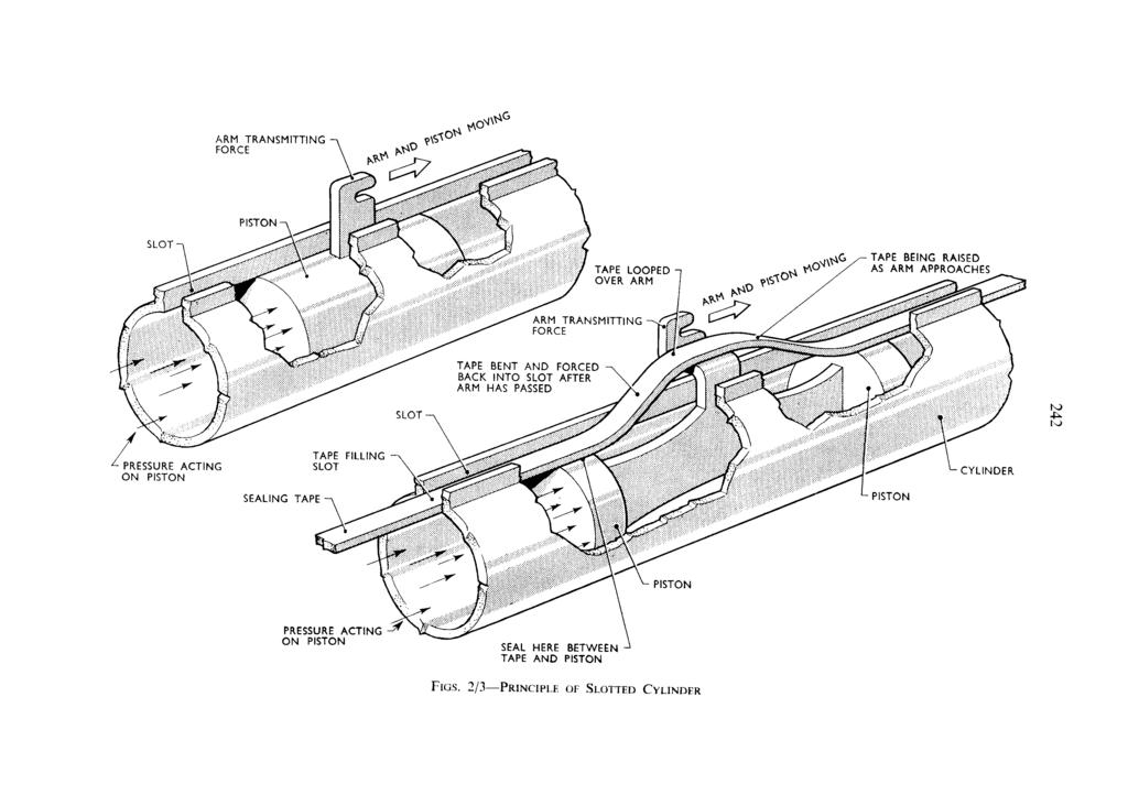
4 parts to withstand them. This would be particularly undesirable in the case of the ropes, since these have to be accelerated to the full speed of the catapult and then sharply brought to rest at the end of the launch. For example, the ropes and other moving parts in a BH5 catapult are equivalent to a weight of 17,000 lb ; this, in addition to the aircraft weight, has to be accelerated to full speed and then decelerated. In the case of a larger hydro-pneumatic catapult the situation would have been still worse and the position approached wherein it would take the catapult all its time to accelerate itself, let alone the aircraft. The Slotted Cylinder Catapult In the circumstances it was necessary to find some alternative mechanism to the hydro-pneumatic cum rope catapult if the high catapult performances desirable from the aircraft designers' point of view were to be met. Various alternatives were considered and eventually it was decided to develop an arrangement based on the slotted cylinder, a device known for many years. Briefly, this consists of a simple piston in a cylinder, which is acted upon by steam or air, or any other convenient medium. In the usual piston and cylinder arrangement the force on the piston is transmitted by a piston rod attached to it, which comes out of the end of the cylinder, frequently through a gland. In the slotted cylinder the method of transmitting the force from the piston is different. A slot is cut along the whole length of the cylinder and an arm is attached to the piston which projects out through this slot. The force on the piston is transmitted through this arm and can therefore be applied to a catapult shuttle, or anything else, without the intermediary use of a long piston rod. This is illustrated in FIG. 2. Of course the obvious problem is how to stop the steam or air, under pressure behind the piston, from merely rushing out through the slot and escaping. This is done by a device very simple in principle. Imagine that the piston is half way down the cylinder with the arm for transmitting the force projecting through the slot. Imagine too, that there is a length of steel tape with which to seal the slot. The best that could be done would be to fit the tape into the clear slot in front of and behind the piston, leaving a loop over the projecting arm and fitting the tape as snugly as possible up to the arm. If the piston was long enough it would extend beyond the looped part of the tape, so that steam behind the piston would find its escape blanked by the piston, and by the part of the tape fitting the slot-it would not be able to get to the part of the tape looped up round the projecting arm. If it is now wished to move the piston, all that is necessary is to pull up the tape in front of the projecting arm as it moves along, and press it down into the slot behind it, that is, to move the loop along with the piston keeping it just over the projecting arm (see FIG. 3). This is the principle of the slotted cylinder, but of course it is a big step to advance from the simple idea to a practical design. The great merit of the slotted cylinder is that the force on the piston is transmitted directly to the catapult shuttle, thus saving all the weight and space and heavy inertia of piston rods and ropes. The decision to attempt to develop a slotted cylinder catapult for aircraft carriers was taken in 1946, and was influenced by the fact that the Germans in the last war had successfully developed and used slotted cylinder catapults for launching V1 flying bombs. The German catapults used hydrogen peroxide to give the operating pressure in the cylinder ; they were simple but very heavy and had many features which were not suitable for ship use, for instance the piston was not retarded at the end of the launch but shot off after the Vl.
5 FOOT FOOT FIG. 4-SECTION THROUGH B.S.4 CATAPULT

6 Design Problems Many problems had to be solved to design a catapult which would be likely to be satisfactory for shipboard use. It was necessary first to devise a practical arrangement of the sealing tape. In practice this is a flexible steel strip, and suitable guides are provided on the piston to lift this over the arm from the piston projecting through the slot. A simple but ingenious arrangement was devised whereby the sealing strip, when in position, is made to serve to hold the two lips of the cylinder slot from opening out ; this is essential since the long slot in the cylinder would naturally weaken its ability to withstand the internal pressure. For shipboard use the loss of the piston with each shot could not be tolerated, so that some means of stopping it at the end of launch is required. This is no mean problem since each piston plus the attached shuttle weighs nearly a ton and must be brought to rest from, say, 120 knots in as short a distance as possible. It has been found possible to achieve this retardation in 5 ft. by fitting a tapered ram projecting from the front of each piston, which enters a thick and strong cylinder at the end of the catapult ; the cylinder is kept full of water by jets, and the water escaping through the narrow gap between the ram and cylinder mouth reaches a very high pressure which brings the piston to rest. The maximum retardation achieved is of the order of 800 g. Numerous other arrangements had to be devised, e.g. for bringing the pistons and shuttle back to the launching position, for securing positive and exact control of admission of steam to the cylinders to get the required launch characteristics, etc. Great attention has been paid to the control arrangements to secure that they should be foolproof in action and give sure, safe launching. The BS4 Catapult for Aircraft Carriers The steam catapult, as now developed for fitting in H.M. aircraft carriers, and bearing the mark BS4, consists of two long slotted cylinders lying side by side in a trough immediately under the flight deck, and extending the whole length of the catapult runway. In each cylinder is a piston with an arm extending through the slot, driving a shuttle, common to both pistons, which runs in a track in the deck and tows the aircraft in the usual manner. (FIG 4 shows a section through such an arrangement.) At the forward end of each cylinder is a water-filled retardation cylinder to bring the pistons and shuttle to rest. Steam for operating the catapult is stored in large receiver drums, two for each catapult ; these are situated one or two decks below the after end of the catapult and are charged by steam supplied from the ship's main boilers. From the receiver drums large bore pipes take the steam to two launching valves, one on the after end of each cylinder ; these control the admission of steam. At the end of a launch the launching valves are closed and a large exhaust valve opens to an exhaust pipe which discharges below the waterline. The control system and the machinery for working the various valves, and for retracting the pistons and shuttle ready for the next launch, are housed in a compartment immediately under the after end of the catapult. The actual firing of the catapult is in the hands of an operator at a deck control position. A typical layout is shown in FIG. 5. The operating sequence is as follows. The pistons are brought to the after end of the cylinders and the receiver drums charged with steam. The aircraft is placed on the catapult in the normal way and the towing bridle and holdback fitted. Using a manoeuvring gear the pistons are moved forward to take up the slack in the bridle and tension up the holdback. On the signal from the directing officer the catapult is fired by opening the launch valves and admitting steam to the cylinder at a controlled rate. At the end of launch the launching
7 CATAPULT POWER CYLINDERS7 \RETRACTING WIRES r RETARDATION UNIT RETRACTING JIGGER LAUNCHING SHUTTLE CONTROL POSITION HYDRAULIC FLUID TANK LAUNCH VALVES HAUST STEAM DISCHARGE OVERBOARD

8 valves are closed and the exhaust valve opened to empty the cylinders. The pistons and shuttle are retracted and the receiver drums recharged with steam from the ship's boilers ready for the next launch. The performance of the BS4 catapults to be fitted in Fleet carriers is very considerably greater than that of the most powerful hydro-pneumatic catapults. The heavier aircraft can be lauflched at greater speeds and lighter aircraft at much greater speeds. This latter is possible largely because the moving parts of the BS4 catapult are so much lighter than in hydro-pneumatic types, so that they can reasonably be brought to rest from much higher speeds at the end of the launch. It should be noted that however powerful the catapult, the end speed it can give is limited by the acceleration which the aircraft (and aircrew) can withstand, and by the length of the catapult runway which the ship design will allow. Thus the shorter the catapult and the less the permissible acceleration, the less is the speed which can be attained. This is a matter of simple kinematics, which is part of the laws of nature and outwith the influence of catapult designers. A prototype BS4 catapult was fitted in a temporary manner in H.M.S. Perseus and given extensive trials in 1951 and Some 1,560 launches were carried out, 355 light, 1,039 with deadloads and 166 with aircraft of nearly all available types, including Attackers, without mishap. In the early stages, as was to be expected, a number of troubles arose and were overcome by changes in detail design. Many possible improvements were also revealed and these have been incorporated in the final design for installation in ships. Without such prototype trials, and also shore trials carried out with the co-operation of the Armament Research Establishment, Ministry of Supply, it would not have been possible to be sure that the catapults being fitted in operational ships would be satisfactory and reliable, without very lengthy trials and subsequent modifications. The catapult trials in H.M.S. Perseus included a visit to the United States in the spring of 1952, where the catapult was demonstrated so successfully that the U.S. Naval Authorities quickly decided to adopt the design and, as has appeared in the public press, have embarked on a programme of fitting it in U.S.N. aircraft carriers. The characteristics to be expected from BS4 catapults in service can best be judged from measurements made during prototype trials in H.M.S. Perseus ~nd from the experience of the pilots of aircraft launched from H.M.S. Perseus. 4part from the greater speeds the most notable feature, which was commented )n by all pilots, was the very smooth acceleration as compared with hydro- ~neumatic catapults. Although the acceleration was, in many cases, high, the :ffects felt were less disturbing due to the absence of jerks. This is because the orce is solely provided and governed by an elastic medium, steam, with only L short connection to the aircraft, as compared with the relatively inelastic vater and the long connection by ropes in the hydro-pneumatic catapult. The catapult is quiet in operation except that the retardation at the end of he stroke gives a severe blow to the ship's structure ; below decks the mpression given is very similar to that of a gun being fired. It was thought hat the discharge of the catapult exhaust underwater might be noisy but in =erseus this was found not to be the case. The BS4 catapults are designed for operation at a greater rate than BH5 br BH3 catapults. A feature which must be of particular interest to aviators is reliability.

9 The BS4 catapult contains many fewer moving parts than the BH3 or BH5 types. Great care has been taken in the design to promote reliability by good detail design and by making arrangements to facilitate maintenance. This latter is most important in catapults as in all machines. No machine will remain reliable without proper servicing and maintenance ; this requires skilled work and sufficient time to do it. Given proper maintenance it is confidently expected that, following the experience in Perseus after initial troubles were overcome, the BS4 catapult will prove entirely reliable. Conclusion That perfection is unattainable is as true of catapults as of any other device. The perfect catapult would be of negligible weight, occupy negligible space and require no maintenance. This cannot be claimed for the new catapult which, though lighter than corresponding hydro-pneumatic catapults, is still of considerable weight and occupies valuable space high up in the ship ; nevertheless it is a considerable advance and, as with any novel device, it is at the beginning of its development so that further improvements and refinements in design may be expected. It is not for the writer of this article to discuss the tactical effect of the greater performance offered by the BS4 catapult, both as regards freedom of carrier operations and in facilitating the use of higher performance aircraft, or in permitting reduction in the size and weight of aircraft for the same performance and endurance, but the benefits would appear to be considerable.
Reducing Landing Distance
 Reducing Landing Distance I've been wondering about thrust reversers, how many kinds are there and which are the most effective? I am having a debate as to whether airplane engines reverse, or does something
CHAPTER 10 STEAM CATAPULTS General
 CHAPTER 10 STEAM CATAPULTS 10.1 General The purpose of the steam catapult is to provide a means to safely launch aircraft from carrier decks, day or night, in almost any kind of weather. The steam catapult
Steam Car Developments and Steam Aviation
 c Steam Car Developments and Steam Aviation Vol. VIII FEBRUARY, 19 W No. 96 Progress Report on the Leslie Steam Car. Those of our readers who have been following' the Magazine since the October, 1937,
Airframes Instructor Training Manual. Chapter 6 UNDERCARRIAGE
 Learning Objectives Airframes Instructor Training Manual Chapter 6 UNDERCARRIAGE 1. The purpose of this chapter is to discuss in more detail the last of the Four Major Components the Undercarriage (or
Introduction: Problem statement
 Introduction: Problem statement The goal of this project is to develop a catapult system that can be used to throw a squash ball the farthest distance and to be able to have some degree of accuracy with
The distinguishing features of the ServoRam and its performance advantages
 ADVANCED MOTION TECHNOLOGIES INC 1 The distinguishing features of the ServoRam and its performance advantages What is a Linear Motor? There are many suppliers of electrical machines that produce a linear
Fig.1 Sky-hook damper
 1. Introduction To improve the ride comfort of the Maglev train, control techniques are important. Three control techniques were introduced into the Yamanashi Maglev Test Line vehicle. One method uses
Stomp Rockets. Flight aboard the USS Hornet. From the USS Hornet Museum Education Department. Sue Renner and Alissa Doyle (rev.
 Stomp Rockets Flight aboard the USS Hornet From the USS Hornet Museum Education Department Sue Renner and Alissa Doyle (rev. May 2018) Alissa.Doyle@uss-hornet.org USS Hornet Museum Education Department
Hydraulic Slide Starts and Stops
 Hydraulic Slide Starts and Stops This guide is intended to assist Heartland Owners in understanding why the Hydraulic Pump may start and stop while operating the slideouts. Who created this document? Important
M:2:I Milestone 2 Final Installation and Ground Test
 Iowa State University AerE 294X/AerE 494X Make to Innovate M:2:I Milestone 2 Final Installation and Ground Test Author(s): Angie Burke Christopher McGrory Mitchell Skatter Kathryn Spierings Ryan Story
SIR HENRY JOHN ORAM H enry O ram
 SIR HENRY JOHN ORAM 1858 1939 H enry O ram was born in June 1858, and though of somewhat frail health, from an early age he showed remarkable intelligence and aptitude for learning and always did well
60 minute physics. Flight and movement. Nine hands-on activities: with GCSE Physics curriculum links. Flight & movement.
 60 minute physics Nine hands-on activities: with GCSE Physics curriculum links Mapping data Digital Electric circuits Machines & electromagnets Light Storing energy Forces & motion Changing states Flight
AMERICAN STOVE APPLICATION ARTICLE: DRAFT (Rev. 3: 2/27/08) Precision Dispensing of Epoxy for Engraved Parts
 Precision Dispensing of Epoxy for Engraved Parts") FISHMAN CORPORATION AMERICAN STOVE APPLICATION ARTICLE: DRAFT (Rev. 3: 2/27/08) Title: Precision Dispensing of Epoxy for Engraved Parts Author: Scott Beebe, President of Fishman Corporation The need to
FISHMAN CORPORATION AMERICAN STOVE APPLICATION ARTICLE: DRAFT (Rev. 3: 2/27/08) Title: Precision Dispensing of Epoxy for Engraved Parts Author: Scott Beebe, President of Fishman Corporation The need to
BULLETIN 507. Mechanical Forging Presses
 BULLETIN 507 Mechanical Forging Presses...-. ~ " The Erie Foundry Company designs and manufactu res quality machine tools that are used around the world. Erie presses have been built to stamp, cut, blank,
White paper: Pneumatics or electrics important criteria when choosing technology
 White paper: Pneumatics or electrics important criteria when choosing technology The requirements for modern production plants are becoming increasingly complex. It is therefore essential that the drive
SPEY SMlC GAS TURBINES
 SPEY SMlC GAS TURBINES IN H.M.S. 'BRAVE' LIEUTENANT-COMMANDER R. W. PARRY, B. SC., C.ENG., M.I.MEcH.E., R.N. AND COMMANDER R. A. DOXSEY, M.Sc., C.ENG., M.I.MEcH.E., R.N. (Sea Systems Con trollerate) ABSTRACT
2.- HANDLING OF VALVES BEFORE ASSEMBLY 3.- FITTING THE VALVE TO THE REST OF THE ASSEMBLY 5.- PERIODICAL INSPECTION OF THE VALVE AND MAINTENANCE
 Page 1 of 16 CONTENTS 1.- INTRODUCTION 2.- HANDLING OF VALVES BEFORE ASSEMBLY 3.- FITTING THE VALVE TO THE REST OF THE ASSEMBLY 4.- OPERATION OF A BALL VALVE 5.- PERIODICAL INSPECTION OF THE VALVE AND
CHAPTER 5 STEAM-POWERED CATAPULTS
 CHAPTER 5 STEAM-POWERED CATAPULTS Steam is the principal source of energy and is supplied to the catapults by the ship's boilers. For this chapter, a brief explanation of the steam system and its major
Initial / Recurrent Ground Take-Home Self-Test: The Beechcraft 58 Baron Systems, Components and Procedures
 Initial / Recurrent Ground Take-Home Self-Test: The Beechcraft 58 Baron Systems, Components and Procedures Flight Express, Inc. This take-home self-test partially satisfies the recurrent ground training
Application of DSS to Evaluate Performance of Work Equipment of Wheel Loader with Parallel Linkage
 Technical Papers Toru Shiina Hirotaka Takahashi The wheel loader with parallel linkage has one remarkable advantage. Namely, it offers a high degree of parallelism to its front attachment. Loaders of this
POD Propulsion. by Massimo Canepa. Where is the Problem? Loss Prevention Committee with Andrea Gennaro and Giulio Gennaro
 POD Propulsion Where is the Problem? by Massimo anepa Loss Prevention ommittee with Andrea Gennaro and Giulio Gennaro Azimuthal thrusters in ship propulsion have existed for many years in various forms.
HEIDENHAIN Measuring Technology for the Elevators of the Future TECHNOLOGY REPORT. Traveling Vertically and Horizontally Without a Cable
 HEIDENHAIN Measuring Technology for the Elevators of the Future Traveling Vertically and Horizontally Without a Cable HEIDENHAIN Measuring Technology for the Elevators of the Future Traveling Vertically
Seven Decades Of Ejection Seat Development
 Seven Decades Of Ejection Seat Development Aviation Week Guy Norris As the industry s largest and oldest consistent ejection seat developer, Martin-Baker has delivered more than 70,000 escape devices since
The 4 Stroke Diesel Cycle
 The 4 Stroke Diesel Cycle Nickolaus Otto invented the 4 stroke cycle in 1862. More details of how the four stroke spark ignition cycle works, together with pictures of Otto's first engines can be found
A basic layout diagram of a papermaking machine is shown below :
 Introduction : A papermaking machine consists of the following sections : A wire and press section (the wet section) A drier section A calender & 4. A reeler A basic layout diagram of a papermaking machine
DYNAMIC BOOST TM 1 BATTERY CHARGING A New System That Delivers Both Fast Charging & Minimal Risk of Overcharge
 DYNAMIC BOOST TM 1 BATTERY CHARGING A New System That Delivers Both Fast Charging & Minimal Risk of Overcharge William Kaewert, President & CTO SENS Stored Energy Systems Longmont, Colorado Introduction
PNEUMATIC BIKES ABSTRACT
 PNEUMATIC BIKES ABSTRACT The fact that you pick up this paper shows that there is something common among all! [f you have your own a two wheeler; if you are spending more money in your petrol; if you feel
Hydraulic energy control, conductive part
 Chapter 2 2 Hydraulic energy control, conductive part Chapter 2 Hydraulic energy control, conductive part To get the hydraulic energy generated by the hydraulic pump to the actuator, cylinder or hydraulic
NZQA registered unit standard version 4 Page 1 of 5
 Page 1 of 5 Title Drive and manoeuvre a steam driven rail vehicle Level 4 Credits 10 Purpose This unit standard covers the knowledge and skills required to drive and manoeuvre steam driven rail vehicles,
XIV.C. Flight Principles Engine Inoperative
 XIV.C. Flight Principles Engine Inoperative References: FAA-H-8083-3; POH/AFM Objectives The student should develop knowledge of the elements related to single engine operation. Key Elements Elements Schedule
OF THE FUTURE-THE PNEUMATIC BIKE ECO FRIENDLY
 ABSTRACT The fact that you pick up this paper shows that there is something common among all! [f you have your own a two wheeler; if you are spending more money in your petrol; if you feel drive in a polluted
Chapter 2 How the Diesel Aircraft Engine Functions
 Chapter 2 How the Diesel Aircraft Engine Functions People who are familiar with the functioning of a gasoline aircraft engine need not have any difficulty in understanding how a high speed Diesel aircraft
PREVOST AIR SYSTEMS WHAT THEY DO AND HOW THEY DO IT
 PREVOST AIR SYSTEMS WHAT THEY DO AND HOW THEY DO IT Air. In our buses we use air for many purposes. We warm ourselves and cool ourselves with it. We supply it to our engines so they will run. Air is what
FRL unit consist of Filterations, Regulators and Lubricator unit.
 4.1 AIR CONTROL 4.1.1 Fluid Conditioner FRL unit consist of Filterations, Regulators and Lubricator unit. It is also known as Air Service Unit. Primary function is to provide clean air at optimal pressure
Rocket Races. Rocket Activity. Objective Students investigate Newton s third law of motion by designing and constructing rocketpowered
 Rocket Activity Rocket Races Objective Students investigate Newton s third law of motion by designing and constructing rocketpowered racing cars. National Science Content Standards Unifying Concepts and
Module7:Advanced Combustion Systems and Alternative Powerplants Lecture 32:Stratified Charge Engines
 ADVANCED COMBUSTION SYSTEMS AND ALTERNATIVE POWERPLANTS The Lecture Contains: DIRECT INJECTION STRATIFIED CHARGE (DISC) ENGINES Historical Overview Potential Advantages of DISC Engines DISC Engine Combustion
Development of a Clutch Control System for a Hybrid Electric Vehicle with One Motor and Two Clutches
 Development of a Clutch Control System for a Hybrid Electric Vehicle with One Motor and Two Clutches Kazutaka Adachi*, Hiroyuki Ashizawa**, Sachiyo Nomura***, Yoshimasa Ochi**** *Nissan Motor Co., Ltd.,
International Journal of Scientific & Engineering Research, Volume 4, Issue 7, July ISSN BY B.MADHAN KUMAR
 International Journal of Scientific & Engineering Research, Volume 4, Issue 7, July-2013 485 FLYING HOVER BIKE, A SMALL AERIAL VEHICLE FOR COMMERCIAL OR. SURVEYING PURPOSES BY B.MADHAN KUMAR Department
THE TORQUE GENERATOR OF WILLIAM F. SKINNER
 THE TORQUE GENERATOR OF WILLIAM F. SKINNER IN 1939, WHICH WAS THE START OF WORLD WAR TWO, WILLIAM SKINNER OF MIAMI IN FLORIDA DEMONSTRATED HIS FIFTH-GENERATION SYSTEM WHICH WAS POWERED BY SPINNING WEIGHTS.
Installation and operating manual Quick closing valve (Bellow sealed) LK product no:
 LK product no:") LK product no: 902002 Article no: 74506 Revision: 2 Contents 1. General information... 3 2. Safety precautions... 3 2.1 Significance of symbols... 3 2.2 Explanatory notes on safety information... 3 3.
LK product no: 902002 Article no: 74506 Revision: 2 Contents 1. General information... 3 2. Safety precautions... 3 2.1 Significance of symbols... 3 2.2 Explanatory notes on safety information... 3 3.
Regents Physics Summer Assignment. Physics: Balloon Car Lab
 Regents Physics Summer Assignment Name: Physics: Balloon Car Lab A rocket is simply a chamber filled with pressurized gas. A small opening called a nozzle allows the air to escape, causing thrust that
6 costly mistakes most hydraulics users make and how you can avoid them!
 6 costly mistakes most hydraulics users make and how you can avoid them! A special advisory report by Brendan Casey - www.hydraulicsupermarket.com Brendan Casey has written over 100 maintenance-related
Unit 2: Lesson 2. Balloon Racers. This lab is broken up into two parts, first let's begin with a single stage balloon rocket:
 Balloon Racers Introduction: We re going to experiment with Newton s Third law by blowing up balloons and letting them rocket, race, and zoom all over the place. When you first blow up a balloon, you re
Development of Motor-Assisted Hybrid Traction System
 Development of -Assisted Hybrid Traction System 1 H. IHARA, H. KAKINUMA, I. SATO, T. INABA, K. ANADA, 2 M. MORIMOTO, Tetsuya ODA, S. KOBAYASHI, T. ONO, R. KARASAWA Hokkaido Railway Company, Sapporo, Japan
How to use the Multirotor Motor Performance Data Charts
 How to use the Multirotor Motor Performance Data Charts Here at Innov8tive Designs, we spend a lot of time testing all of the motors that we sell, and collect a large amount of data with a variety of propellers.
I) Clamping the work piece II) Drilling the work piece. III) Unclamping the work piece. 10
 Clamping the work piece II) Drilling the work piece. III) Unclamping the work piece. 10") Seventh Semester B.E. III IA Test, 2014 USN 1 P E M E PES INSTITUTE OF TECHNOLOGY (Bangalore South Campus) (Hosur Road, 1KM before Electronic City, Bangalore-560 100) Department of Mechanical Engineering
Seventh Semester B.E. III IA Test, 2014 USN 1 P E M E PES INSTITUTE OF TECHNOLOGY (Bangalore South Campus) (Hosur Road, 1KM before Electronic City, Bangalore-560 100) Department of Mechanical Engineering
Unit V HYDROSTATIC DRIVE AND ELECTRIC DRIVE
 Unit V HYDROSTATIC DRIVE AND ELECTRIC DRIVE HYDROSTATIC DRIVE In this type of drives a hydrostatic pump and a motor is used. The engine drives the pump and it generates hydrostatic pressure on the fluid.
(Review X-Model and V-Model)
") Overview (Review X-Model and V-Model) The O3U Corsair was the first new aircraft produced at the East Hartford plant, and the first complete aircraft to be tested full-scale in a wind tunnel at Langley
Overview (Review X-Model and V-Model) The O3U Corsair was the first new aircraft produced at the East Hartford plant, and the first complete aircraft to be tested full-scale in a wind tunnel at Langley
Development of High Power Column-Type Electric Power Steering System
 TECHNICAL REPORT Development of High Power Column-Type Electric Power Steering System Y. NAGAHASHI A. KAWAKUBO T. TSUJIMOTO K. KAGEI J. HASEGAWA S. KAKUTANI Recently, demands have increased for column-type
Railway Technical Web Pages
 Railway Technical Web Pages Archive Page Vehicle Suspension Systems Introduction Almost all railway vehicles use bogies (trucks in US parlance) to carry and guide the body along the track. Bogie suspension
Using Pneumatic Cylinders in Rivet, Hole Punch & Broaching applications
 How to control pneumatic cylinder forces Using Pneumatic Cylinders in Rivet, Hole Punch & Broaching applications Begin with force-multiplying Pneumatic Cylinders Multi-Power Air Cylinders from Fabco-Air
THE PROTECTION OF INDUSTRIAL CAPACITOR BANKS BY CURRENT LIMITING FUSES. By M.J. Smart and B. Wadcock
 203 THE PROTECTION OF INDUSTRIAL CAPACITOR BANKS BY CURRENT LIMITING FUSES By M.J. Smart and B. Wadcock 1.0 INTRODUCTION Capacitors are widely used for industrial power factor correction throughout the
HPB Hydraulic Power Braking System
 HPB Hydraulic Power Braking System 4 th Edition This publication is not subject to any update service. New versions are available in INFORM at www.wabco-auto.com Copyright WABCO 2007 Vehicle Control Systems
Series: hydraulic-type control in pneumatic machinery
 Adding Adding the the control, control, rigidity rigidity and and power power of of hydraulics hydraulics to to aa pneumatic pneumatic machine machine Control with Air-Oil Tanks Air-Oil tanks provide a
Hours / 100 Marks Seat No.
 17412 16117 3 Hours / 100 Seat No. Instructions (1) All Questions are Compulsory. (2) Answer each next main Question on a new page. (3) Illustrate your answers with neat sketches wherever necessary. (4)
INDIAN INSTITUTE OF TECHNOLOGY KHARAGPUR NPTEL ONLINE CERTIFICATION COURSE. On Industrial Automation and Control
 INDIAN INSTITUTE OF TECHNOLOGY KHARAGPUR NPTEL ONLINE CERTIFICATION COURSE On Industrial Automation and Control By Prof. S. Mukhopadhyay Department of Electrical Engineering IIT Kharagpur Topic Lecture
Variable Valve Drive From the Concept to Series Approval
 Variable Valve Drive From the Concept to Series Approval New vehicles are subject to ever more stringent limits in consumption cycles and emissions. At the same time, requirements in terms of engine performance,
SWINDON ENGINEERING SOCIETY. BRAKES FOR MODERN EXPRESS PASSENGER TRAINS,
 [No 127.] G.W.R. Mechanics Institution. SWINDON ENGINEERING SOCIETY. TRANSACTIONS, 1920-21 ORDINARY MEETING February 22nd, 1921. Chairman Mr. F. W. Hawksworth. BRAKES FOR MODERN EXPRESS PASSENGER TRAINS,
Self-Adjusting Clutch (SAC) Technology Special tools / User instructions
 Technology Special tools / User instructions") Self-Adjusting Clutch (SAC) Technology Special tools / User instructions The content of this brochure shall not be legally binding and is for information purposes only. To the extent legally permissible,
Self-Adjusting Clutch (SAC) Technology Special tools / User instructions The content of this brochure shall not be legally binding and is for information purposes only. To the extent legally permissible,
The low wing Cessna 170 a great idea that didn t fly
 The low wing Cessna 170 a great idea that didn t fly Air Facts Journal Harry Clements The three views, of the airplane described by the article title, that accompany this piece were taken from an unofficial
Chapter01 - Control system types - Examples
 Chapter01 - Control system types - Examples Open loop control: An open-loop control system utilizes an actuating device to control the process directly without using feedback. A common example of an open-loop
Aircraft Engine Development from Fundamental Considerations: Thermodynamic and Mechanical
 24 1 Aircraft Engine Development from Fundamental Considerations: Thermodynamic and Mechanical 2 Ideal Cycles 8 3 Lect-24 Q 1 W 1 Q 1 W 1 W 2 7 2 W 2 4 Heat exchanges are : Q 1 ~ c v (T 3 T 2 )>c v (T
MOTORS, VOLTAGE, EFFICIENCY AND WIRING. A Deeper Understanding
 MOTORS, VOLTAGE, EFFICIENCY AND WIRING A Deeper Understanding An understanding of motors, voltage, efficiency, wiring, and how these concepts fit together cohesively is important for several reasons. Greater
UNIT IV INTERNAL COMBUSTION ENGINES
 UNIT IV INTERNAL COMBUSTION ENGINES Objectives After the completion of this chapter, Students 1. To know the different parts of IC engines and their functions. 2. To understand the working principle of
HE Stewart Vacuum Gasoline System employs a small tank, installed under the hood. This tank is connected by brass tubing to the intake manifold, also
 T HE Stewart Vacuum Gasoline System employs a small tank, installed under the hood. This tank is connected by brass tubing to the intake manifold, also to gasoline supply tank, and to carburetor. Every
Fabric Pulse Jet Collector Early Designs (Circa 1963)
") Fabric Pulse Jet Collector Early Designs (Circa 1963) To expand in the application area for process streams that operate at higher temperatures and corrosive conditions, an improved fabric pulse jet collector
Fabric Pulse Jet Collector Early Designs (Circa 1963) To expand in the application area for process streams that operate at higher temperatures and corrosive conditions, an improved fabric pulse jet collector
Toyota Landcruiser Rear Brake Upgrade Package
 May 2007 Toyota Landcruiser Rear Brake Upgrade Package 9 Nevada Ct Hoppers Crossing Vic 3029 Ph 03 97486950 Fax 03 97485965 Email hopstop@hoppers.com.au Web www.hoppers.com.au 2 THE INFORMATION CONTAINED
The Facts on. WHATReally Affects FUEL ECONOMY? Number. in a series of 6
 The Facts on 1 Number in a series of 6 WHATReally Affects FUEL ECONOMY? As Congress considers developing an energy policy, the 13-member Alliance of Automobile Manufacturers is providing a series of fact
Hybrid Drives for Mobile Equipment
 Hybrid Drives for Mobile Equipment 2nd Symposium of the VDMA and the University of Karlsruhe (TH) 18 February, 2009 Karlsruhe An event sponsored jointly by Calculable Economy: Hydraulic Hybrid Drivetrain
 AUTOGARD SERIES 820 TORQUE LIMITER Installation and Maintenance Manual DB0009 Issue 11 21 Feb 2017 British Autogard Ltd 2 Wilkinson Rd., Love Lane Industrial Estate, Cirencester, Glos., GL7 1YT UK Tel.
Navy Case No Date: 10 October 2008
 DEPARTMENT OF THE NAVY NAVAL UNDERSEA WARFAE CENTER DIVISION NEWPORT OFFICE OF COUNSEL PHONE: 401 832-3653 NEWPORT FAX: 401 832-4432 DSN: 432-3653 Navy Case No. 96674 Date: 10 October 2008 The below identified
Project Spartan. An Innovative Light Frigate Design for General Purpose Frigate (GPFF)
") Project Spartan An Innovative Light Frigate Design for General Purpose Frigate (GPFF) The 2015 Strategic Defence and Security Review (SDSR) announced that the Royal Navy is looking to procure five light
Project Spartan An Innovative Light Frigate Design for General Purpose Frigate (GPFF) The 2015 Strategic Defence and Security Review (SDSR) announced that the Royal Navy is looking to procure five light
Selection of low-cost recovery system for Unmanned Aerial Vehicle
 Selection of low-cost recovery system for Unmanned Aerial Vehicle Abinaya.R 1, R. Arravind 2 1M.E Aeronautical Engineering, Department of Aeronautical Engineering, Nehru institute of Engineering and Technology,
CHAPTER 3 ENGINE TYPES
 CHAPTER 3 CHAPTER 3 ENGINE TYPES CONTENTS PAGE Multi-Cylinders 02 Firing orders 06 2 Stroke Cycle 08 Diesel Cycle 10 Wankel Engine 12 Radial/Rotary 14 Engine Types Multi Cylinders Below are illustrated
Metrovick F2/4 Beryl. Turbo-Union RB199
 Turbo-Union RB199 Metrovick F2/4 Beryl Development of the F2, the first British axial flow turbo-jet, began in f 940. After initial flight trials in the tail of an Avro Lancaster, two F2s were installed
Electric Drives CHAPTER1 LEARNING OBJECTIVES INTRODUCTION
 CHAPTER1 Electric Drives LEARNING OBJECTIVES After the completion of this unit, students/readers will be able to understand: 1. What is a drive? Why electric drives are preferred over mechanical drives.
HDT-RMCS DIESEL MILITARY MOTORCYCLE
 HDT-RMCS DIESEL MILITARY MOTORCYCLE Introduction The programme by the Royal Military College of Science [RMCS] and Hayes Diversified Technologies [HDT] to design and develop a diesel motorcycle was undertaken
Alfa Laval s new FCM One is a single answer to today s fuel conditioning challenges
 Editorial December 2013 Alfa Laval s new FCM One is a single answer to today s fuel conditioning challenges Much has changed since Alfa Laval launched the Fuel Conditioning Module, or FCM, in 2001. Booster
Extending the Operation Range of Dry Screw Compressors by Cooling Their Rotors
 Purdue University Purdue e-pubs International Compressor Engineering Conference School of Mechanical Engineering 2004 Extending the Operation Range of Dry Screw Compressors by Cooling Their Rotors Nikola
Aircraft Maintenance Prof. A.K Ghosh Prof. Vipul Mathur Department of Aerospace Engineering Indian Institute of Technology, Kanpur
 Aircraft Maintenance Prof. A.K Ghosh Prof. Vipul Mathur Department of Aerospace Engineering Indian Institute of Technology, Kanpur Lecture 05 Aircraft Landing Gear System Now, coming to the next aircraft
OBSERVATIONS ABOUT ROTATING AND RECIPROCATING EQUIPMENT
 OBSERVATIONS ABOUT ROTATING AND RECIPROCATING EQUIPMENT Brian Howes Beta Machinery Analysis, Calgary, AB, Canada, T3C 0J7 ABSTRACT This paper discusses several small issues that have occurred in the last
An advisory circular may also include technical information that is relevant to the rule standards or requirements.
 Revision 0 Electrical Load Analysis 2 August 2016 General Civil Aviation Authority advisory circulars contain guidance and information about standards, practices, and procedures that the Director has found
10 questions and answers about electric cars
 10 questions and answers about electric cars https://www./en/innovation/10-questions-answers-electric-cars/ The future of cars will be electric. But what does this mean in practice? How far will the cars
Maximum Flow: 600 GPM (3800 LPM) Portable Base 1250 GPM (4800 LPM) Direct Mount. Maximum Pressure: 200 PSI (1380 Kpa, 13.8 BARS)
 Portable Base 1250 GPM (4800 LPM) Direct Mount. Maximum Pressure: 200 PSI (1380 Kpa, 13.8 BARS)") STYLE 3414 Apollo S.I. Monitor with FoldING Legs OPERATING & MAINTENANCE INSTRUCTIONS WITH SPECIAL L.A. COUNTY SPECIFICATIONS The Akron Style 3414 Apollo Monitor is designed to provide efficient trouble-free
STYLE 3414 Apollo S.I. Monitor with FoldING Legs OPERATING & MAINTENANCE INSTRUCTIONS WITH SPECIAL L.A. COUNTY SPECIFICATIONS The Akron Style 3414 Apollo Monitor is designed to provide efficient trouble-free
ROTARY VERSUS RECIPROCATING ENGINES
 ROTARY VERSUS RECIPROCATING ENGINES Rotary versus Reciprocating Engines Ships, Planes and Cars Yes, I know it should be Trains boats and planes but hear me out. In 1906, the British battleship Dreadnought
Introduction. 1.2 Hydraulic system for crane operation
 Two control systems have been newly developed for fuel saving in hydraulic wheel cranes: namely, a one-wayclutch system and an advanced engine control system. The former allows one-way transmission of
ELECTRIC CURRENT. Name(s)
") Name(s) ELECTRIC CURRT The primary purpose of this activity is to decide upon a model for electric current. As is the case for all scientific models, your electricity model should be able to explain observed
Name(s) ELECTRIC CURRT The primary purpose of this activity is to decide upon a model for electric current. As is the case for all scientific models, your electricity model should be able to explain observed
PRESENTATION ON HYDRAULIC BASED COMPONENT
 PRESENTATION ON HYDRAULIC BASED COMPONENT 1.HYDRAULIC CRANE 2.HYDRAULIC LIFT 3.HYDRAULIC ACCUMULATOR 4.HYDRAULIC INTENSIFIER 5.JET PUMP PRESENTED BY: GAURAV SHARMA HYDRAULIC CRANE The hydraulic crane is
Assemblies for Parallel Kinematics. Frank Dürschmied. INA reprint from Werkstatt und Betrieb Vol. No. 5, May 1999 Carl Hanser Verlag, München
 Assemblies for Parallel Kinematics Frank Dürschmied INA reprint from Werkstatt und Betrieb Vol. No. 5, May 1999 Carl Hanser Verlag, München Assemblies for Parallel Kinematics Frank Dürschmied Joints and
... Tianjin Port Coal Loading Conveyor. *E. J. O DONOVAN & Associates, Brisbane Australia. Edmond O Donovan* and Gordon Butler
 ........... Tianjin Port Coal Loading Conveyor Edmond O Donovan* and Gordon Butler ABSTRACT As part of an overall expansion of the coal transport infrastructure in China, the Port of Tianjin is working
Advantages of the Hüttlin-Kugelmotor over the reciprocating piston engine
 Advantages of the Hüttlin-Kugelmotor over the reciprocating piston engine The Hüttlin-Kugelmotor corresponds with a four cylinder reciprocating piston engine because each full work stroke, consisting of
TRAILER TECHNOLOGY. KNOTT Trailer systems Individually tailored to your needs
 TRAILER TECHNOLOGY Tr a i l er systems AG R IC U LTU R E KNOTT Trailer systems Individually tailored to your needs www.knott.de We make your brake 1 TRAILER TECHNOLOGY Every project is special. Everything
CONFERENCE ON AVIATION AND ALTERNATIVE FUELS
 International Civil Aviation Organization WORKING PAPER 3/11/09 English only CONFERENCE ON AVIATION AND ALTERNATIVE FUELS Rio de Janeiro, Brazil, 16 to 18 November 2009 Agenda Item 2: Technological feasibility
Factors to consider when selecting a diverter valve
 Factors to consider when selecting a diverter valve Selecting a diverter valve for your pneumatic conveying system can be a tough job, especially when you consider how many diverter valves are on the market.
(12) United States Patent (10) Patent No.: US 6,643,958 B1
 United States Patent (10) Patent No.: US 6,643,958 B1") USOO6643958B1 (12) United States Patent (10) Patent No.: Krejci (45) Date of Patent: Nov. 11, 2003 (54) SNOW THROWING SHOVEL DEVICE 3,435,545. A 4/1969 Anderson... 37/223 3,512,279 A 5/1970 Benson... 37/244
USOO6643958B1 (12) United States Patent (10) Patent No.: Krejci (45) Date of Patent: Nov. 11, 2003 (54) SNOW THROWING SHOVEL DEVICE 3,435,545. A 4/1969 Anderson... 37/223 3,512,279 A 5/1970 Benson... 37/244
Development of Internationally Competitive Solid Rocket Booster for H3 Launch Vehicle
 Development of Internationally Competitive Solid Rocket Booster for H3 Launch Vehicle YANAGISAWA Masahiro : Space Launch Vehicle Project Office, Rocket Systems Department, IHI AEROSPACE Co., Ltd. KISHI
Review and Proposal of Exhaust gas operated air brake system for automobile
 Review and Proposal of Exhaust gas operated air brake system for automobile Shriram Pawar 1, Praful Rote 2, Pathan Sahil, Mohd Sayed 4 1 BE student Mechanical, SND COE & RC, YEOLA, Maharashtra,India 2
Insight. Hyperloop transportation of the future
 Insight Hyperloop transportation of the future John Colvin Principal Gabbie Anastasi Research Assistant Five years ago, Elon Musk, creator of Tesla, published a white paper on a theoretical system called
12/2013 We would like to express our gratitude to both our customers and modellers for their respect and favour in this December
 Newsletter MPM Production Ltd., Mezilesí 718, 193 00, Praha 9, Czech Republic tel.:+420 281923 910, fax:+420 281 923 892, e-mail: export@mpm.cz official website and e-shop: www. cmkkits.com 12/2013 We
Flight Testing of Your Europa Equipped with the Airmaster Propeller By Bud Yerly Custom Flight Creations, Inc.
 Flight Testing of Your Europa Equipped with the Airmaster Propeller By Bud Yerly Custom Flight Creations, Inc. Once you've selected the desired blade and hub for your Airmaster constant speed propeller,