Single-Phase Step Voltage Regulator
|
|
|
- Bernadette Bennett
- 5 years ago
- Views:
Transcription


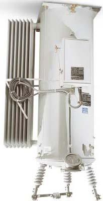
1 Single-Phase Step Voltage Regulator - Overhead Mounted - Page 1 of 12
2 Table of Contents 1 GENERAL CONSTRUCTION RIV REQUIREMENT REGULATOR CONTROLS TESTS EVALUATION CONTROL INTERROGATION SOFTWARE DEVIATION FROM SPECIFICATION SHIPPING INSTRUCTIONS APPENDIX A - EQUIPMENT DATA SHEET APPENDIX B - DEVIATIONS FROM SPECIFICATIONS Page 2 of 12
3 1 GENERAL 1.1 This specification covers electrical, mechanical and safety features and characteristics of outdoor, single phase, oil immersed, 60 Hz, 65 o C temperature rise by resistance, self cooled and force-air cooled step-type voltage regulators. The voltage regulators must be completely selfcontained and provide +/- 10% voltage regulation in thirty-two (32) steps of 5/8% each. The voltage regulator shall be of a sealed tank design that will allow operation at 65 0 C without increasing the oxidation rate of the oil. 1.2 STANDARDS - The regulators furnished under this specification shall be designed, manufactured, and tested in accordance with ANSI Standard C57.15, latest revision thereof. That standard shall be a part of this specification 1.3 RATINGS - All ratings shall be for 60 Hertz alternating current, oil-immersed, air-cooled voltage regulators capable of continuous operation at rated kva without exceeding a 55 0 C average temperature rise above 40 0 C ambient at it s rated current with a 10% raise or 10% lowering of tap positions. The basic impulse level (BIL) shall be 95 kv. The nominal system voltage will be 12,470 GRD Y/ 7200 volts. Single-phase operation shall be at a nominal voltage of 7200 volts. 1.4 The voltage regulators shall have the following capacities: kva RATING AMPERE RATING* 38 50/ / / / / /490 *The first value shall be the 55 0 C rating. The value to the right of the slash shall be the ampere rating at 65 0 C. 2 CONSTRUCTION 2.1 PRESSURE RELIEF DEVICE All voltage regulators shall be designed such that all excessive pressure build-ups are released without damage to the tank or the release of excessive amounts of oil All voltage regulators shall be equipped with a mechanical, self-resetting pressure relief device, venting between 4 PSIG and 10 PSIG. Page 3 of 12
4 2.2 VOLTAGE REGULATOR OIL Voltage regulators shall be insulated with new (unused) mineral oil. The oil shall meet the requirements of ANSI C , Article (1), ANSI C and ASTM 3487 Type The voltage regulator nameplate shall indicate that the PCB content of said voltage regulator is less than I PPM or that at time of manufacture gas chromatographic analysis certified non-detectable PCB The oil shall be inhibited mineral oil containing 0.2 percent by weight DBPC The nameplate shall show the gallons of oil. 2.3 HIGH VOLTAGE BUSHINGS AND TERMINALS Voltage regulators shall be equipped with three identical and interchangeable, covermounted, wet process porcelain high voltage bushings with clamp type terminals in accordance with ANSI C57.15, latest revision. The BIL of the Bushings shall meet or exceed 95 kv. The bushings shall be light gray in color and the minimum creep shall be 16 inches. The bushings shall have the following clamp-type terminals: VOLTAGE REGULATOR SIZE CLAMP TERMINAL SIZE RANGE 150 AMP AND BELOW #6 TO 250 KCMIL ABOVE 150 AMP AND #6 TO 500 KCMIL BELOW 300 AMP ABOVE 300 AMP #6 TO 800 KCMIL All clamp terminals shall be marked according to the latest revision of ANSI C The clamp type terminal shall be capable of being tightened with a 9/16 inch Fargo wrench (Fargo Manufacturing, Catalog No. GP-203) The bushing designations (S, L, or SL) shall be permanently marked on the regulator cover adjacent to the associated bushings All regulators shall be provided with a metal oxide varister (MOV) bypass arrester connected across the series winding All regulators shall be provided with polymer housed lightning arresters, riser pole, 9kV, 7.65 MCOV, with isolator and wildlife protector, connected to the source, and load bushings. Cooper URS0905-0A1A-1A1A or equivalent. Arresters shall be mounted on removable brackets The physical arrangement of the high-voltage terminations shall per Figure #3 of ANSI Standard C Wildlife Protector - A factory provided wildlife protector shall be included on the high voltage bushings and series arrester. Page 4 of 12
5 2.4 VOLTAGE REGULATOR TANKS Voltage regulator tanks shall be of sealed tank design with welded steel construction The overall size of the voltage regulators and the weight of the voltage regulators, once filled with oil, shall not exceed the following: SIZE (AMP) WEIGHT (LBS) HEIGHT* (INCHES) WIDTH** (INCHES) DEPTH*** (INCHES) *Height shall be measured from bottom of tank to top of primary terminal at top of primary bushing or arrester (if arrester is higher than terminal). **Width shall be measured from hanger bracket to lifting hook or cooling fin at farthest point from hanger bracket. * * *Depth shall be measured from cooling fin to outside of control box if it were mounted on tank All tanks shall be furnished with an external oil sight gauge, which indicates both oil level and oil color Voltage regulators rated 150 amperes and below shall be pole-mounted and provided with welded-on hanger brackets. Voltage regulators rated 219 amperes and above shall be provided with a base suitable for securing them to a pad or elevating structure. All voltage regulators must be capable of being secured to an elevating structure All tanks shall be furnished with either handholds in the lid or with an externally mounted and accessible terminal block to allow easy access to potential transformer connections. The covers to these items shall be gasketed and removable All regulators shall be designed so that they can be partially or completely untanked for inspection and maintenance without disconnecting any internal electrical or mechanical connections. After the unit is untanked, it shall be possible to operate the regulator mechanism and to test the control panel from an external 120 VAC source without any reconnections between the control and the regulator Tanks shall come equipped with all accessories prescribed in the latest revision of ANSI C57.15 in addition to those described in these specifications. 2.5 GROUNDING PROVISIONS Voltage regulators shall be furnished with ground provisions as specified in the latest revision of ANSI C Grounding provisions shall be 300 series stainless steel. The grounding provisions shall be tapped with 1/2"-13 NC holes that shall have a minimum thread depth of 0.5 inches. Each grounding provision shall be welded to the lower portion of the tank of the voltage Page 5 of 12
6 regulator in such a manner as to protect the integrity of the threaded holes. Threads shall NOT be painted and shall be protected with a plug during shipping. 2.6 TAP CHANGER The tap changing mechanism shall be a motor driven, quick-break design and it shall be completely oil immersed The tap changer shall be able to go from full buck to full boost in under 25 seconds. 2.7 PAINT FINISH The external parts of the voltage regulator shall have a primer coat of special rustresisting paint. The primer coat shall be followed by two coats of finish paint. All paint applied shall be highly resistant to oil and weathering. The finish coat shall be semigloss ANSI 70 sky gray color All finishes shall be certified to meet or exceed the latest revisions of ANSI C The top of the voltage regulator lid shall have at least 3.0 mils of paint. The voltage regulator sides and bottom shall have at least 3.0 mils of paint. The inside of the voltage regulator shall have at least 3.0 mils of paint from a point 2 inches below the oil level up to and including the inside of the top cover. Complete painting of the inside is acceptable Two One Quart Cans of paint used for the final coat shall be shipped with each line item. 2.8 NAMEPLATES Each regulator shall be provided with two nameplates mechanically fastened; one mounted on the control enclosure and the other mounted on the regulator tank. Nameplates shall be made of stainless steel or laser etched anodized AL and permanently marked with essential operating data as specified in the latest revision of ANSI C The voltage regulator nameplate shall specifically state that the voltage regulator is mineral oil filled and the number of gallons of oil it contains. The nameplate shall also indicate that the PCB content of said voltage regulator is less than 1 PPM or that at the time of manufacture gas chromatographic analysis certified non-detectable PCB All nameplates shall have the manufacturer's serial number bar-coded into the nameplate. Manufacturer identification characters shall not be included as part of the barcode. This barcode shall be etched into the nameplate. The character size shall be ¼ inch. The barcode shall be a minimum of 1/2 inch high and 2-1/2 inches wide The District also desires the following information be provided on similar nameplates located on both the control panel and tank. Impedance at the 16 raise position and rated kva Diagram-matic sketch of the windings Ratio correction transformer taps and corresponding system voltages Untanking weight Page 6 of 12
7 Weight of tank and fittings Weight of oil in use District purchase order numbers 3 RIV REQUIREMENT The radio influence voltage shall not exceed 100 microvolts (average measurement) at 1000 khz measured at 115 percent of rated voltage in accordance with NEMA Specification TR-1. 4 REGULATOR CONTROLS The District approved regulator control panel is the latest version of the Cooper CL-6A.The following settings and/or options shall be provided. 4.1 REVERSE POWER FLOW OPERATION All voltage regulators shall be provided with reverse power flow detectors properly assemble on the unit. The reverse power flow detector shall be capable of detecting power flow in the reverse direction and insuring that the automatic voltage control of the regulator is sensing what is effectively the load or output voltage of the unit. If required a (source-to-load) differential potential transformer (PT) shall be supplied as part of this voltage regulator accessory. The addition of the PT shall also permit metering for reverse power flow conditions. The PT shall be located internally to the regulator tank. 4.2 TAP POSITION INDICATOR An external position indicator shall indicate the tap changer position. The position indicator shall be mounted above the oil level and shall be slanted downward to enable easy reading from below, when the regulator is pole mounted. 4.3 LOAD BONUS CAPABILITY All voltage regulators shall include a feature that will permit additional current carrying capabilities at reduced regulation according to the following schedule: REGULATION (PERCENT) CURRENT (% OF 55 0 C Rating) +/ / / / The adjustment for the load bonus device shall be located inside the faceplate of the tap position indicator to prevent inadvertent adjustment. Page 7 of 12
8 4.4 CONTROL PANEL The regulator control panel shall be mounted in a weather-resistant enclosure, which is capable of being padlocked. The control enclosure shall have an external grounding provisions that shall be 300 series stainless steel. The grounding provisions shall be tapped with 1/2"-13 NC holes that shall have a minimum thread depth of 0.5 inches. Each grounding provision shall be welded to the control enclosure in such a manner as to protect the integrity of the threaded holes. Threads shall NOT be painted and shall be protected with a plug during shipping The control panel shall be hinge-mounted and designed for easy replacement. The front panel shall be constructed to provide direct control interchangeability without requiring the removal of the control enclosure. Visible means shall be provided to de-energize the control and short the current transformer prior to testing or removal of the control All leads in the control shall be either color coated or labeled for easy identification All printed circuit boards shall be conformal coated for fungi and moisture protection A ratio correction transformer shall be provided inside the control enclosure to provide easy access to fine voltage adjustment. Ratio correction taps and corresponding system voltage shall be clearly identified on the regu1ator nameplates. A software provision to provide this feature in the control will also be accepted The regulator control panel shall be microprocessor based with an event recorder that has the ability to time stamp all events placed in the event recorder. The control panel shall have the ability to digitally meter with Class 1 accuracy, as defined in the latest revision of ANSI C The control panel shall have USB update and download capabilities and be compatible with the Cooper Proview NXG software The control panel shall operate properly over a temperature range of minus 40 C to plus 85 C A thermostatically controlled heater assembly to reduce moisture shall be provided. The Heater shall be equipped with an "ON-OFF" switch. In the "ON" position the thermostat in the heater shall activate the heater at approximately 85 F and turn the heater "OFF" at approximately 100 F The controls shall include remote mounting cable to allow the remote placement of the regulator controls. The cable shall be 45 feet in length and shall be pre-connected at the factory. The bottom 10 feet of cable shall be armored The control panel shall have a digital communication port(s) located on the front panel. The port(s) shall allow trouble-free communications between a laptop (or personal computer or Data Reader) and the control panel. The successful Bidder at no additional cost to the District shall supply all accessories and software for trouble-free communications Fiber-Optic Communication for Remote Access utilizing the DNP 3.0 protocol. Page 8 of 12
9 Retaining springs to secure manuals to the cabinet shall be supplied on the inside of the enclosure. Storage of the manuals, in this manner, shall not adversely affect the control unit The control panel shall allow automatic operation of the voltage regulator under reverse power flow conditions. The reverse power flow detector shall operate within the following limits: Sensitivity - reverse power flow detected at two percent (2%) of the rated 55 C load current of the regulator Load power factor lag to 0.55 lead Input Voltage to 140 volts, 60 Hertz. Potential transformer shall be internally located for input voltage requirements Ambient Temperature - minus 30 C to plus 50 C The motor starting capacitor shall be located inside the Control panel and be easily accessible for maintenance. 5 TESTS 5.1 Each voltage regulator shall receive complete tests at the factory in accordance with latest ANSI C57.15 and NEMA TR In addition, every voltage regulator be operated for a minimum of 250 operations, stepping through multiple steps in both the raise and lower directions to verify correct control and tap changer operation and to assure that all infant failures are detected at the factory. 5.3 Copies of Certified test reports shall be available for District inspection at the District's request. Test reports shall be sent to District prior to shipping the regulators. 5.4 At the option of the District, voltage regulators may be tested for acceptance upon receipt. 5.5 SHORT CIRCUIT WITHSTAND - All voltage regulators shall be capable of withstanding, without damage, short circuit currents as specified in the latest revision of ANSI C Page 9 of 12
10 6 EVALUATION 6.1 Appendix A of this specification must be completely filled out for bid/quote to be evaluated. Prices will be firm for delivery date specified. Failure to include prices and/or delivery in the appropriate blank for each item will be sufficient cause for rejection of bid. 6.2 For bid evaluation, regulator losses will be considered. The evaluation price will be calculated using the following equation: REP=BP + (NL) ($4.07) + LL ($1.79) REP Regulator Evaluation Price BP Base Bid Price NL* Core Loss (Watts) LL* Conductor Loss (Watts) * For loss evaluation purposes, loss values at 16 raise in the Bidder s Data shall be used. 7 CONTROL INTERROGATION SOFTWARE 7.1 Software required to interrogate, modify, and download control panel functions, and event recorder shall be capable with Microsoft Windows XP & 7 operating systems. 7.2 Included with the software shall be a site license that would allow for the software to be installed on any personal computer and server that Chelan PUD deems necessary. 8 DEVIATION FROM SPECIFICATION 8.1 It is expected that any regulators supplied by the vendor will be in strict accordance with this specification unless appropriately noted with the original bid. The purchaser reserves the right to evaluate any exceptions that are taken by a vendor. Any deviation from this specification without prior approval will be sufficient cause for rejection of the regulators furnished and/or rejection of that manufacturer from furnishing the equipment in the future. All deviations shall be note on the Appendix B form Deviations From Specifications 9 SHIPPING INSTRUCTIONS 9.1 Voltage regulators shall be shipped completely assembled in an enclosed van and filled with the proper amount of voltage regulator oil. 9.2 Voltage regulators shall be shipped on individual pallets (one voltage regulator per pallet). Voltage regulators shall be securely attached to the pallets to allow for forklift handling. 9.3 Voltage regulators shipped on a flatbed truck or having damaged or broken securing devices shall be cause to reject delivery. Page 10 of 12
11 10 APPENDIX A - EQUIPMENT DATA SHEET Line Item Number: Delivery Date: Description: Manufacture: Model Control Cabinet Manufacture & Model Number Temperature Rating Size Voltage Rating Ampere Rating AMP Manufacture of pressure relief device Model number of pressure relief device Percent Z* Design Working Pressure at Tank Total Weight: Untanking Weight: Oil Weight: Case & Fittings Weight: Shipping Weight: Number of turns in series winding Number of turns in shunt winding Series winding wire material Shunt winding wire material Type of core material Maximum Megger voltage that can be applied to Series Winding Maximum Megger Voltage that can be applied to Shunt winding Volume of Oil: Maximum ampacity of switch assembly Maximum ampacity of contacts Recommended number of tap changer operations per contact prior to inspection. Lifetime number of tap changer operations per contact. Lifetime number of total tap changer operations per contact at full load current and 0.8 power factor. Height Width Depth Core loss at 16 raise at full load, rated current Conductor losses at 16 raise at full load, rated current: 0 C kva kv AMP PSI Lbs. Lbs. Lbs. Lbs. Lbs. kv kv Gal Amps Amps Inches Inches Inches Watts Watts Page 11 of 12
12 11 APPENDIX B - DEVIATIONS FROM SPECIFICATIONS Page 12 of 12
Three-Phase Pole Mounted Recloser
 Three-Phase Pole Mounted Recloser Page 1 of 8 Table of Contents 1 GENERAL... 3 2 CONSTRUCTION... 3-5 3 BUSHINGS... 5 4 LINE CONNECTOR... 5 5 TOOLS....5 6 NAMEPLATES..6 7 PAINT... 6 8 EXTERNAL HARDWARE
A. Three-phase, oil filled self-cooled, padmounted transformers are installed outdoors on pads in the EWEB distribution system.
 1. APPLICATION A. Three-phase, oil filled self-cooled, padmounted transformers are installed outdoors on pads in the EWEB distribution system. 2. REFERENCE STANDARDS A. The transformers supplied shall
DISTRIBUTION TRANSFORMERS SPECIFICATION #
 DISTRIBUTION TRANSFORMERS SPECIFICATION #1212.01 12.47kV Grd Wye Padmount & Polemount Bid No. 16-93 Exhibit I Page 1 of 19 TABLE OF CONTENTS 1 SCOPE... 3 2 STANDARDS... 3 3 EVALUATION AND AWARD... 3 4
Single-Phase Step Voltage Regulators
 Voltage Regulators Catalog Data CA225001EN Supersedes March 2017 COOPER POWER SERIES Single-Phase Step Voltage Regulators Contents GENERAL....2 STANDARD FEATURES....4 OPTIONAL ACCESSORIES...4 ARRESTERS....4
NEW Solutions for Underground System Growth
 NEW Solutions for Underground System Growth Cooper s Single-Phase Voltage Regulator Improved Power Quality More Economical Improved System Reliability Increased Safety Better Aesthetics Lower Maintenance
Howard Industries. Single-Phase Step
 Howard Industries Utility Products Division Single-Phase Step Catolog Section 28-10 Voltage Regulators INTRODUCTION Howard Industries SVR-1 single-phase step voltage regulators are tapchanging autotransformers
CLARK PUBLIC UTILITIES TECHNICAL SPECIFICATIONS THREE-PHASE PADMOUNTED TRANSFORMERS
 CLARK PUBLIC UTILITIES TECHNICAL SPECIFICATIONS THREE-PHASE PADMOUNTED TRANSFORMERS Originated 1/85 Revised 6/95 Revised 6/02 Revised 11/05 Revised 4/08 Revised 11/09 Revised 1/12 Revised 11/12 Revised
CLARK PUBLIC UTILITIES TECHNICAL SPECIFICATIONS THREE-PHASE PADMOUNTED TRANSFORMERS
 CLARK PUBLIC UTILITIES TECHNICAL SPECIFICATIONS THREE-PHASE PADMOUNTED TRANSFORMERS Originated 1/85 Revised 6/95 Revised 6/02 Revised 11/05 Revised 4/08 Revised 11/09 Revised 1/12 Revised 11/12 Revised
Single-phase step voltage regulators
 Voltage Regulators Catalog Data CA225001EN Supersedes 225-10 February 2014 COOPER POWER SERIES General Eaton's Cooper Power series VR-32 singlephase step voltage regulators are tap-changing autotransformers.
SPECIFICATION FOR THREE-PHASE PAD MOUNT TRANSFORMERS. D. Dead Front, loop feed design shall be employed.
 City of Cartersville Electric System P.O. Box 1390 320 S. Erwin St. Cartersville, GA 30120 770-387-5631 March 2006 SPECIFICATION FOR THREE-PHASE PAD MOUNT TRANSFORMERS This specification provides standardization
MATERIAL SPECIFICATION ELECTRIC OPERATIONS ORGANIZATION. M3902 ****Supercedes BECo Standard E and ComElectric Spec ****
 Page 1 of 8 ****Supercedes BECo Standard E2.12-2.12 and ComElectric Spec 6-0895**** 1.0 General Requirements SINGLE PHASE PAD-MOUNTED DISTRIBUTION TRANSFORMERS 1.1 These specifications cover single-phase
Figure 1. Single-phase pad-mounted voltage regulator. STANDARD FEATURES
 Voltage Regulators Single-Phase Pad-mounted Step GENERAL McGraw-Edison Single-Phase Padmounted Voltage Regulators add a dimension to underground system planning. They provide system planners freedom to
Technical Specification for Pole Mounted Capacitor Rack
 Technical Specification for Pole Mounted Rack Page 1 1. Scope and Function a) Pole mounted capacitor racks shall be installed on a distribution feed as an economical means of applying capacitor units to
MATERIAL STANDARD ELECTRIC OPERATIONS ORGANIZATION. ****Supercedes BECo Standard E and ComElectric Spec ****
 Page 1 of 8 ****Supercedes BECo Standard E2.12-2.14 and ComElectric Spec 7-0895**** THREE-PHASE DEADFRONT PAD-MOUNTED DISTRIBUTION TRANSFORMERS, LOOP & RADIAL FEED DESIGNS 1.0 General Requirements 1.1
CITY OF LOMPOC UTILITIES DEPARTMENT ELECTRICAL DIVISION SPECIFICATION NO. ELE-115
 CITY OF LOMPOC UTILITIES DEPARTMENT ELECTRICAL DIVISION SPECIFICATION NO. ELE-115 PADMOUNTED TRANSFORMERS 12kV AND DUAL VOLTAGE, RADIAL FEED STAINLESS STEEL NOVEMBER 2011 Specification:ELE_115_R1 Page
S Voltage Regulators. Contents. VR-32 Voltage Regulator with Quik-Drive Tap-Changer Installation, Operation, and Maintenance Instructions
 Voltage Regulators VR-32 Voltage Regulator with Quik-Drive Tap-Changer Installation, Operation, and Maintenance Instructions Service Information S225-10-30 Figure 1. VR-32 Voltage Regulator with Quik-Drive
GENERAL INFORMATION POLE MOUNT TRANSFORMER SINGLE PHASE PAD MOUNT TRANSFORMER SINGLE PHASE POLE MOUNT TRANSFORMER THREE PHASE 17
 GENERAL INFORMATION SECTION GUIDE SECTION 10 PAGE 1 DESCRIPTION SECTION NUMBER GENERAL INFORMATION... 10 POLE MOUNT TRANSFORMER SINGLE PHASE... 15 PAD MOUNT TRANSFORMER SINGLE PHASE..... 16 POLE MOUNT
43-SDMS-01 SPECIFICATIONS FOR
 SPECIFICATIONS FOR MV SHUNT POWER CAPACITOR BANK UP TO 36 KV This specification is property of SEC and subject to change or modification without any notice CONTENTS Clause Description Page 1.0 SCOPE 3
C. System Design and Performance Requirements
 Change History Date Description of Change Pages / Sections Modified 6/15/16 Updated division section from 16361-E-E to 26 10 03, removed references to other section numbers A. Summary - mgl44 Change Approver
SECTION PADMOUNT TRANSFORMER - OIL FILLED
 SECTION 26 12 19.01 PADMOUNT TRANSFORMER - OIL FILLED PART 1 GENERAL 1.1 DESCRIPTION: Padmount Transformers and Insulating Oil with underground primary and secondary connections for use in distribution
Underground Distribution Switchgear
 Underground Distribution Switchgear Functional Specification Guide Functional Specification for 15 kv, 25 kv, or 35 kv Underground Distribution Switchgear 1. Scope 1.1. This specification applies to three-phase,
SUBSTATION VACUUM CIRCUIT BREAKER (38KV)
") SUBSTATION VACUUM CIRCUIT BREAKER (38KV) For more than four decades, Myers Power Products has led the switchgear market in quality for the electric industry, delivering highly reliable products for utilities
SUBSTATION VACUUM CIRCUIT BREAKER (38KV) For more than four decades, Myers Power Products has led the switchgear market in quality for the electric industry, delivering highly reliable products for utilities
SUBSTATION VACUUM CIRCUIT BREAKER (25.8 / 27KV)
") SUBSTATION VACUUM CIRCUIT BREAKER (25.8 / 27KV) For more than four decades, Myers Power Products has led the switchgear market in quality for the electric industry, delivering highly reliable products
SUBSTATION VACUUM CIRCUIT BREAKER (25.8 / 27KV) For more than four decades, Myers Power Products has led the switchgear market in quality for the electric industry, delivering highly reliable products
CITY OF LOMPOC UTILITIES DEPARTMENT ELECTRICAL DIVISION SPECIFICATION NO. ELE-112 SUBSTATION CLASS VACUUM CIRCUIT BREAKERS OCTOBER 2008
 CITY OF LOMPOC UTILITIES DEPARTMENT ELECTRICAL DIVISION SPECIFICATION NO. ELE-112 SUBSTATION CLASS VACUUM CIRCUIT BREAKERS OCTOBER 2008 SPECIFICATION NO: ELE_112_R1.doc Page 1 of 3 Rev. 10/28/2008 SPECIFICATION
SUBSTATION VACUUM CIRCUIT BREAKER (15.5KV)
") SUBSTATION VACUUM CIRCUIT BREAKER (15.5KV) For more than four decades, Myers Power Products has led the switchgear market in quality for the electric industry, delivering highly reliable products for utilities
SUBSTATION VACUUM CIRCUIT BREAKER (15.5KV) For more than four decades, Myers Power Products has led the switchgear market in quality for the electric industry, delivering highly reliable products for utilities
Michigan State University Construction Standards SECONDARY UNIT SUBSTATIONS PAGE
 PAGE 261116-1 SECTION 261116 PART 1 - GENERAL 1.1 RELATED DOCUMENTS A. Drawings and general provisions of the Contract, including General and Supplementary Conditions and Division 01 Specification Sections,
CENTER BREAK GROUP OPERATED AIR BREAK SWITCHES RATED 15.5kV THROUGH 170kV EFFECTIVE DATE: 10/25/16 REV B
 CENTER BREAK GROUP OPERATED AIR BREAK SWITCHES RATED 15.5kV THROUGH 170kV EFFECTIVE DATE: 10/25/16 REV B TCV2 Hubbell has a policy of continuous product improvement. Please visit hubbellpowersystems.com
Design Standard. Purpose: Design Standard:
 Design Standard Purpose: This design standard has the purpose of creating a consistent application of motor-control centers throughout the East Side Union High School District, therefore achieving a standard
SPECIFICATION FOR THREE PHASE PAD-MOUNT DISTRIBUTION TRANSFORMERS
 SPECIFICATION T-5 SPECIFICATION FOR THREE PHASE PAD-MOUNT DISTRIBUTION TRANSFORMERS 1.0 GENERAL PURPOSE 1.1 These specifications cover the electrical and mechanical features of a three phase, 60 hertz,
35-kV Safefront SuperWell Mini-Switch Source Isolated Pad-Mounted Switchgear 50 Amp (Max) Clip-Mounted Current Limiting Fuses
 Clip-Mounted Current Limiting Fuses") Page 1 2016 EPMR-35-311S-R2/ESW-CM9 Three Phase Two Ways per Phase 200 Amp 35 kv Class Eaton s CPS LRTPs 50 Amp (Max) 27 kv Clip-Mounted NX Fuse Provisions 21.1/36.6 kv Grounded Wye Max Design, 150 kv
Page 1 2016 EPMR-35-311S-R2/ESW-CM9 Three Phase Two Ways per Phase 200 Amp 35 kv Class Eaton s CPS LRTPs 50 Amp (Max) 27 kv Clip-Mounted NX Fuse Provisions 21.1/36.6 kv Grounded Wye Max Design, 150 kv
Technical Specification For Outdoor Substation Harmonic Filter Banks
 Technical Specification For Outdoor Substation Harmonic Filter Banks One of Three 5th, 11th & 23rd, 34.5 kv, Rated Harmonic Filter Assemblies Provided for a Central Venezuela Heavy Oil Production Field
Drive Duty Transformer Specification Virginia Transformer Corp. Power Up! Selecting the Right Transformer
 Drive Duty Transformer Specification Virginia Transformer Corp. Power Up! Selecting the Right Transformer This document contains sample specifications for Liquid-Filled Type Drive Transformers You may
10 Commercial, Industrial, Agricultural Services
 10 Commercial, Industrial, Agricultural Services This section describes the Power Company requirements for commercial, industrial, and agricultural services. This section covers single phase and three
Single-phase pad-mounted step voltage regulator
 Voltage Regulators Catalog Data CA225002EN Supersedes February 2015 COOPER POWER SERIES Single-phase pad-mounted step voltage regulator General Eaton's Cooper Power series single-phase pad-mounted voltage
Product Specifications for Phase Over Phase GOABS(r)
") 1. General a) This specification covers the design, manufacture, and shipment of phase-over-phase, 1-way, 2-way, 3-way, and 4-way, gang-operated disconnecting switches, both air-break and load-break, for
1. General a) This specification covers the design, manufacture, and shipment of phase-over-phase, 1-way, 2-way, 3-way, and 4-way, gang-operated disconnecting switches, both air-break and load-break, for
COOPER POWER SERIES. VR-32 Voltage Regulator with Quik-Drive Tap-Changer Installation, Operation, and Maintenance Instructions
 Voltage Regulators MN225008EN Effective February 2017 Supersedes May 2015 COOPER POWER SERIES VR-32 Voltage Regulator with Quik-Drive Tap-Changer Installation, Operation, and Maintenance Instructions DISCLAIMER
Single phase pole mounted. 11kV. Electrical Engineer KEU ID#:
 Single phase pole mounted Distribution Transformers 11kV Prepared by: ARY SAIDAHMED SHEKSAEED Electrical Engineer KEU ID#: 4252 Email: ary.sayd@hotmail.com 1 S # Contents Page # 1 Introduction 3 2 Type
35-kV Safefront 200 Amp SuperWell Primary Metering Station Pad-Mounted Outdoor
 35-kV Safefront 2 Amp SuperWell 5-33 Page 1 216 EPM-PMS-35-311P-R2/ESW Three Phase Two Ways per Phase 2 Amp 35 kv Class Eaton's CPS LRTPs NEMA Standard Outdoor Instrument Transformer Provisions 21.1/36.6
Product Specifications for Aluminum Vertical Break Switches
 1. General a) This specification covers the design, manufacture, and shipment of aluminum vertical break switches, both air-break and load-break configurations, for substation and transmission switching
SUBSTATION TYPE TRANSFORMER - MINERAL OIL FILLED THREE PHASE OISC 65 C RISE 60 HERTZ
 QUALITROL TRANSFORMER BY VANTRAN 10 VAC PSIG 0 5 5 QUALITROL 10 PRESS PSIG 0 40 60 80 20 100 QUALITROL 120 25c SUBSTATION TYPE TRANSFORMER - MINERAL OIL FILLED THREE PHASE OISC 65 C RISE 60 HERTZ 115"
15-kV Live Terminal 600 Amp Group Operated Pad-Mounted Metal-Enclosed Outdoor Switchgear 140 Amp (Max) Clip Mount Current-Limiting Fuses
 Clip Mount Current-Limiting Fuses") Page 1 2015 Heavy duty 11-gauge steel enclosure is all-welded construction for long life Corrosion proof nameplate is located to provide easy access for the operator Glass reinforced barriers meet NEMA
Page 1 2015 Heavy duty 11-gauge steel enclosure is all-welded construction for long life Corrosion proof nameplate is located to provide easy access for the operator Glass reinforced barriers meet NEMA
15-kV Wall-Mount Switchgear Three-Phase Indoor/Outdoor 600 Amp S&C Mini-Rupter Switch
 Page 1 2015 Kinked roof prevents standing moisture Glass reinforced barriers meet NEMA GPO-3 Standards 0.625" diameter copper ground bar Elliott air-insulated bushings accept IEEE Standard inserts and
Solid Dielectric Load Break Switch SPECIFICATION. 25kV, 630A, 4 WAYS, 4 WAYS SWITCHED PADMOUNTED VACUUM LOAD INTERRUPTER
 Solid Dielectric Load Break Switch SPECIFICATION 25kV, 630A, 4 WAYS, 4 WAYS SWITCHED PADMOUNTED VACUUM LOAD INTERRUPTER MANUALLY OPERATED / REMOTELY OPERATED DEAD FRONT PADMOUNTED VACUUM LOAD INTERRUPTING
SERIES 802 / 812 SPECIFICATION 15KV & 25KV PADMOUNTED LIQUID-INSULATED VACUUM LOAD INTERRUPTERS AND FUSE ASSEMBLIES
 SERIES 802 / 812 SPECIFICATION 15KV & 25KV PADMOUNTED LIQUID-INSULATED VACUUM LOAD INTERRUPTERS AND FUSE ASSEMBLIES MANUALLY OPERATED / REMOTELY OPERATED DEAD FRONT PADMOUNTED SWITCHGEAR WITH VACUUM LOAD
Solid Dielectric, Single Phase Recloser
 Solid Dielectric, Single Phase Recloser Catalog O-vsp17 Viper-SP Viper-SP solid dielectric, single phase recloser combines the time-proven reliability of electronically controlled, vacuum fault interrupters
Product Specification Guide. Title: Southern States 72 kv RLSwitcher Vertical Interrupter Style Reactor Switcher
 TABLE OF CONTENTS PAGE 1.0 SCOPE... 2 2.0 STANDARDS... 2 3.0 DESIGN REQUIREMENTS... 2 3.01 Service Conditions... 2 3.02 Ratings... 3 3.03 Interrupter... 3 3.04 SF6 Gas System... 4 3.05 Terminal Pads...
Underground Distribution Switchgear
 Underground Distribution Switchgear Functional Specification Guide Functional Specification for 15 kv, 25 kv, or 35 kv Underground Distribution Switchgear 1. Scope 1.1. This specification applies to three-phase,
Typical Specification
 Engineered to Order Built to Last Typical Specification VAULT VRPFI, TWO POSITION, ROTARY PUFFER SWITCHGEAR PART 1- GENERAL 1.1 DESCRIPTION A. The switch shall consist of manually operated load interrupting,
Product Specification Guide. Title: Southern States 362 kv RLSwitcher Vertical Interrupter Style Reactor Switcher
 TABLE OF CONTENTS PAGE 1.0 SCOPE... 2 2.0 STANDARDS... 2 3.0 DESIGN REQUIREMENTS... 2 3.01 Service Conditions... 2 3.02 Ratings... 2 3.03 Interrupter... 3 3.04 SF6 Gas System... 4 3.05 Terminal Pads...
Solid Dielectric, Single Phase Reclosers
 Solid Dielectric, Single Phase Reclosers Providing electronic overcurrent protection for single phase operation on systems rated through 38kV, 800A continuous current,12.5ka symmetrical interrupting Reliable
A. Motors shall be designed, built, and tested in accordance with the latest revision of the following standard documents.
 PART 1: GENERAL 1.01 This standard is intended to provide useful information to the Professional Service Provider (PSP) to establish a basis of design. The responsibility of the engineer is to apply the
35-kV Safefront 200 Amp SuperWell Primary Capacitor Station Pad-Mounted Outdoor
 Page 1 2016 EPM-PCS-35-320P-R2/ESW-GCM6-2S-SA Three Phase Two Ways per Phase 200 Amp 35 kv Class Eaton's CPS LRTPs 35 kv Elliott Air-Insulated SuperWell Bushings 21.1/36.6 kv Grounded Wye Max Design, 150
Publication No.: PSG
 TABLE OF CONTENTS PAGE 1.0 SCOPE...2 2.0 STANDARDS...2 3.0 DESIGN REQUIREMENTS...2 3.01 Service Conditions... 2 3.02 Ratings... 3 3.03 Resistors... 3 3.04 Interrupter... 4 3.05 SF 6 Gas System... 4 3.06
BUSWAY Low Voltage (Pow-R-Flex)
") BUSWAY LOW VOLTAGE (POW-R-FLEX) PART 1 GENERAL 1.01 1.02 SCOPE The Contractor shall furnish and install the busway system including all necessary fittings, hangers and accessories as specified herein and
BUSWAY LOW VOLTAGE (POW-R-FLEX) PART 1 GENERAL 1.01 1.02 SCOPE The Contractor shall furnish and install the busway system including all necessary fittings, hangers and accessories as specified herein and
Guide Specification. Three-Phase Solid Dielectric Trident-SR with SafeVu Integral Visible Break
 Part 1-GENERAL 1.1 DESCRIPTION Guide Specification Three-Phase Solid Dielectric Trident-SR with SafeVu Integral Visible Break The switchgear shall consist of magnetically actuated solid dielectric insulated
A. Submit manufacturer's literature and technical data before starting work.
 SECTION 16425 SWITCHBOARD PART 1 GENERAL 1.01 SUMMARY A. Related Section: 1. 16450 - Grounding. 1.02 SUBMITTALS A. Submit manufacturer's literature and technical data before starting work. B. Submit Shop
University of Houston Master Construction Specifications Insert Project Name
 SECTION 26 13 13 MEDIUM VOLTAGE SWITCHGEAR PART 1 - GENERAL 1.1 RELATED DOCUMENTS: A. The Conditions of the Contract and applicable requirements of Divisions 0 and 1 and Section 26 00 01, Electrical General
ENTRANCE EQUIPMENT ER D PAGE 1 OF 5
 PAGE 1 OF 5 USE: Requirements for entrance equipment. PREVIOUS REVISION 07-01-98 ORIGINATED 03-94 PREVIOUS NUMBER ER 100 (12-01-81) LATEST REVISION: Updated meter socket labeling specification and instrument
CITY OF MARYVILLE ELECRIC DEPARTMENT Maryville, Tennessee SPECIFICATIONS FOR 15KV POWER CIRCUIT BREAKERS. September 2018
 CITY OF MARYVILLE ELECRIC DEPARTMENT Maryville, Tennessee SPECIFICATIONS FOR 15KV POWER CIRCUIT BREAKERS September 2018 Myrick Clinton Cannon TN P.E. #112337 Patterson & Dewar Engineers, Inc. P. O. Box
INSTRUCTION MANUAL #103
 INSTRUCTION MANUAL #103 www.ermco eci.com THREE PHASE PAD MOUNT DISTRIBUTION TRANSFORMER General instruc ons for installa on and opera on of Three Phase Pad Mount Distribu on Transformer. 2 INTRODUCTION
SECTION PANELBOARDS
 SECTION 16470 PANELBOARDS PART 1 - GENERAL 1.1 RELATED DOCUMENTS A. The general provisions of the contract including General and Special Conditions and General Requirements shall apply to all work under
TRINETICS CSD SERIES OIL SWITCH INSTALLATION INSTRUCTIONS
 TRINETICS CSD SERIES OIL SWITCH INSTALLATION INSTRUCTIONS 33220900 DECEMBER 2011 Caution: The equipment covered by these installation instructions should be installed and serviced only by properly trained
www. ElectricalPartManuals. com Substation Transformers Primary or Secondary Open
 Substation Transformers Primary or Secondary Open GENERAL Cooper Power Systems Primary or Secondary Open Substation Transformers are designed to meet exact customer specifications. Flexibility in design,
9. Non-Residential Services (Commercial, Industrial, and Agricultural)
") Section 9 2016 Electric Service Requirements, 3rd Edition Section 9 Non-Residential Services Directory Page 9.1 General Requirements 68 9.2 Direct-Connect Metering, Single Installations 69 9.3 Direct-Connect
Section 9 2016 Electric Service Requirements, 3rd Edition Section 9 Non-Residential Services Directory Page 9.1 General Requirements 68 9.2 Direct-Connect Metering, Single Installations 69 9.3 Direct-Connect
Cobra-S. Catalog Cobra-S
 Cobra-S Solid Dielectric, Three Phase Reclosers Providing electronic three phase overcurrent protection for systems rated through 38kV, 800A continuous current, 12.5/16kA symmetrical interrupting Control
15-kV Safefront 200 Amp Primary Capacitor Station Pad-Mounted Outdoor
 Page 1 2015 Heavy-duty 11-gauge steel enclosure is all-welded construction for long life Clear polycarbonate removable safety barrier separates upper and lower compartment (supplied only with internally
Horizontal Circuit Switchers
 > Transformer Protection > CIRCUIT SWITCHERS C A T A L O G B U L L E T I N General Application Southern States Types CSH and CSH-B Horizontal Circuit Switchers provide an economical, versatile, space saving
Horizontal Circuit Switchers
 > Transformer Protection > CIRCUIT SWITCHERS C A T A L O G B U L L E T I N General Application Southern States Types CSH and CSH-B Horizontal Circuit Switchers provide an economical, versatile, space saving
Submersible Vacuum Fault Interrupters
 Submersible Vacuum Fault Interrupters UG Distribution Medium Voltage Vacuum Fault Interrupters Functional Specification Guide PS024002EN Functional Specification for 2.4kV to 17.5kV UG Distribution Medium
1500 kva Pad Mount Transformer GRDY/14400V Primary - 208Y/120 Wye Secondary - Oil Cooled
 1500 kva Pad Mount Transformer - 24940GRDY/14400V Primary - 208Y/120 Wye Secondary - Oil Cooled Part #: MT-PMO-3P-24940GRDY.14400-1500KVA-208Y.120-N3R Page: 1 The MT-PMO-3P-24940GRDY.14400-1500KVA-208Y.120-N3R
CONTROLLIX CORPORATION CONTROLLIX.COM LOW VOLTAGE AUTOMATIC SWITCH CAPACITOR BANK SPECIFICATIONS
 LOW VOLTAGE AUTOMATIC SWITCH CAPACITOR BANK SPECIFICATIONS I. SCOPE a. This specification describes the necessary requirements for the design, fabrication, and operation of automatically switched, low
www. ElectricalPartManuals. com Substation Transformers Primary or Secondary Unit
 Substation Transformers Primary or Secondary Unit GENERAL Cooper Power Systems Primary or Secondary Unit Substation Transformers are designed to meet exact customer specifications. Flexibility in design,
100 / 110 DRYWELL FUSE SPECIFICATION
 100 / 110 DRYWELL FUSE SPECIFICATION 15KV & 25KV SUBMERSIBLE VACUUM LOAD INTERRUPTERS AND DRYWELL FUSE ASSEMBLIES MANUALLY OPERATED / REMOTELY OPERATED SUBMERSIBLE SWITCHGEAR WITH LOAD INTERRUPTING SWITCHES
C1000 Series Automatic Cap Bank
 C1000 Series Automatic Cap Bank Metal Enclosed - Medium Voltage Capacitors Assemblies Fixed / Auto Medium Voltage 5, 15, 25 and 35 kv Class Customized to your specifications The Reactive Power Solution
045 : 2000 CEB STANDARD
 045 : 2000 CEB STANDARD LOW VOLTAGE FUSE SWITCH DISCONNECTOR CEYLON ELECTRICITY BOARD SRI LANKA Specification for LOW VOLTAGE FUSE SWITCH DISCONNECTOR CEB Standard 045 : 2000 CEYLON ELECTRICITY BOARD No.
STATE OF NEW JERSEY DEPARTMENT OF TRANSPORTATION TRENTON, NEW JERSEY 08625
 STATE OF NEW JERSEY DEPARTMENT OF TRANSPORTATION TRENTON, NEW JERSEY 08625 SPECIFICATIONS FOR A 19 INCH RACK BASE MOUNT (HEATER/AC) (ENVIRONMENTAL FIELD TERMINAL CABINET) N. J. Specification No. Effective
Transformer bushings, type GOH. Technical guide
 Transformer bushings, type GOH Technical guide This Technical Guide has been produced to allow transformer manufacturers, and their designers and engineers, access to all the technical information required
distribution transformers. Single-Phase Overhead GENERAL. Cooper Power Systems manufactures a complete line of single-phase overhead-type
 Distribution Transformers Single-Phase Overhead Electrical pparatus 0-0 GENERL ooper Power Systems manufactures a complete line of single-phase overhead-type distribution transformers. Single-phase transformers
Metal-Enclosed Switches. Medium Voltage. Medium Voltage Metal-Enclosed Switches Contents
 January 2003 Vol. 1, Ref. No. [1011] -1 Medium Voltage Metal-Enclosed Switches Contents Description Page MVS................................... -2 and Breaker MSB........................ -3 Metal-Enclosed
SERIES G100 / G110 SPECIFICATION 15KV & 25KV SUBMERSIBLE & VAULT MOUNTED SF 6 -INSULATED VACUUM LOAD INTERRUPTING SWITCHES
 SERIES G100 / G110 SPECIFICATION 15KV & 25KV SUBMERSIBLE & VAULT MOUNTED SF 6 -INSULATED VACUUM LOAD INTERRUPTING SWITCHES MANUALLY OPERATED / REMOTELY OPERATED DEAD FRONT SUBMERSIBLE AND VAULT MOUNTED
35-kV Safefront 200 Amp Primary Metering Station Pad-Mounted Outdoor
 ulletin Page 1 2016 Heavy duty 11-gauge steel enclosure is all-welded construction for long life 11-gauge steel equipment plate is rigid for easier elbow operation Upper parking stands extend 3" per IEEE
Solid Dielectric, Three Phase Reclosers CATALOG VS11
 Solid Dielectric, Three Phase Reclosers Providing electronic, three phase overcurrent protection for systems rated through 38kV, 800A continuous current, 12.5kA symmetrical interrupting Reliable performance
A. Fan motors and associated equipment shall be sized to operate at 110% of calculated loads and capacities.
 PART 1: GENERAL 1.01 This design guidelines contained herein includes the requirements electric motors utilized for electric motor driven systems at Texas State University. It is the intention of this
FIXED POWER FACTOR CORRECTION EQUIPMENT 5KV CLASS MEDIUM VOLTAGE SECTION Z
 PART 1 GENERAL 1.01 1.02 1.03 1.04 1.05 SCOPE The Contractor shall furnish and install fixed power factor correction equipment as specified herein and as shown on the contract drawings. This specification
Distribution Transformers
 Distribution Transformers PEAK Three-Phase Pad-mounted Compartmental Type Functional Specification Guide Functional Specification for Three-Phase Pad-Mounted PEAK Distribution Transformers 45 10,000 kva
Q pole Pole Mounted Capacitor System
 Q pole Pole Mounted Capacitor System Introduction The ABB Qpole pole mount capacitor system is an economical solution for shunt reactive compensation on overhead distribution networks. The Qpole is suitable
Special Specification 6058 Battery Back-Up System for Signal Cabinets
 Special Specification Battery Back-Up System for Signal Cabinets 1. DESCRIPTION 2. DEFINITIONS Install a Battery Back-Up System (BBU System) for traffic signals that will provide reliable emergency power
Kuhlman Electric Corporation Volt Instrument Transformers
 Kuhlman Electric Corporation 46000 Volt Instrument Transformers 46000 Volt Table of Contents Description Model Page Wound, Dry-Type VT (High Accuracy available) U/VRU-52(H) 3-4 Wound, Oil-Filled VT (High
Section SWITCHBOARDS. Introduction. Part 1 - General. Related Work
 Section 16435 - SWITCHBOARDS Introduction Part 1 - General Related Work Section 16070 Seismic Anchorage and Restraint Section 16075 Electrical Identification Section 16080 Power Distribution Acceptance
A. Products shall be designed, manufactured, tested, and installed in compliance with the following standards:
 SECTION 26 29 13 ENCLOSED MOTOR CONTROLLERS PART 1 - GENERAL 1.1 RELATED DOCUMENTS: A. The Conditions of the Contract and applicable requirements of Divisions 0 and 1 and Section 26 00 01, Electrical General
PPS20 COMMUNICATIONS POWER SUPPLY AND BATTERY MANAGEMENT SYSTEM
 PPS20 COMMUNICATIONS POWER SUPPLY AND BATTERY MANAGEMENT SYSTEM 2 Table of Contents Introduction:... 3 1.0: Operation Principles:... 3 1.1: Stand alone supply... 3 1.2: Backed up supply:... 3 1.3: Battery
Fixed, Medium-Voltage, Pad-Mounted, Three-Phase Power Capacitor Bank Guide Form Specification
 Fixed, Medium-Voltage, Pad-Mounted, Three-Phase Power Capacitor Bank Guide Form Specification 1. General 1.1 This specification is for a fixed, medium-voltage, padmounted, three-phase power capacitor bank
COOPER POWER CA280012EN
 Reclosers Catalog Data CA280012EN Supersedes May 2014 (290-25) COOPER POWER SERIES Type VSA20B air-insulated, vacuum, electronically Description The Type VSA20B electronically controlled, vacuum circuit
Underground Distribution Switchgear
 Underground Distribution Switchgear Type VFI, Vacuum Fault Interrupter Switchgear Functional Specification Guide Functional Specification for 15 kv, 25 kv, or 35 kv Underground Distribution Switchgear
Professional Wireless Products
 Page 1 of 6 093115 Communications Power Supply and Battery Management Controller Page 2 of 6 1.0 Introduction The 093115 is a 13.8 volt 15amp transformer isolated switch mode down converter designed to
ENGINEERING SPECIFICATION
 December 206 ENGINEERING SPECIFICATION No. of 6 DATE: 2-9-6 CATEGORY SUBJECT TABLE OF CONTENTS. Overview... 2 2. General Requirements for Service... 3 3. Definitions... 3 4. Abbreviations... 5 5. References
A. Work Included: Provide low voltage switchboard work as shown, scheduled, indicated, and as specified.
 SECTION 26 24 13 LOW VOLTAGE SWITCHBOARDS PART 1 - GENERAL 1.1 RELATED DOCUMENTS: A. The Conditions of the Contract and applicable requirements of Divisions 0 and 1 and Section 26 00 01, Electrical General
Automatic, Medium-Voltage, Pad-Mounted, Three-Phase Power Capacitor Bank Guide Form Specification
 Automatic, Medium-Voltage, Pad-Mounted, Three-Phase Power Capacitor Bank Guide Form Specification 1. General 1.1 This specification is for an automatic, medium-voltage, padmounted, three-phase power capacitor
SECTION MOTOR REQUIREMENTS for HVAC
 PART 1 GENERAL 1.1 SECTION INCLUDES A. Single-phase electric motors B. Three-phase electric motors 1.2 REFERENCES SECTION 23 05 13 MOTOR REQUIREMENTS for HVAC A. ABMA 9 - Load Ratings and Fatigue Life
15-kV Live Terminal Primary Metering Station Pad-Mounted Outdoor
 ulletin Page 1 2015 Cross-kinked roof prevents standing moisture Metering Transformer compartment label is visible with doors closed Heavy duty 11-gauge steel enclosure is all-welded construction for long