DISTRIBUTION TRANSFORMERS SPECIFICATION #
|
|
|
- Amos Paul
- 6 years ago
- Views:
Transcription


1 DISTRIBUTION TRANSFORMERS SPECIFICATION # kV Grd Wye Padmount & Polemount Bid No Exhibit I Page 1 of 19
2 TABLE OF CONTENTS 1 SCOPE STANDARDS EVALUATION AND AWARD INFORMATION TO BE FURNISHED WITH BID POLEMOUNT TRANSFORMERS PAD MOUNT TRANSFORMER SINGLE PHASE PAD-MOUNTED TRANSFORMERS THREE PHASE TRANSFORMER OIL NOISE PAINT FINISH INSPECTION TESTS WORKMANSHIP, MATERIAL, AND FINISH DELIVERY METHODS SPECIFICATIONS REVISIONS LOG Bid No Exhibit I Page 2 of 19
3 1 SCOPE This specification is to cover minimum requirements for Polemount & Padmount type, outdoor, oil-immersed distribution transformers suitable for operation on the District s 12470GrdY/7200 Volt Distribution System. 2 STANDARDS All material and equipment furnished under these specifications shall conform to the latest applicable approved standards of IEEE, ANSI, NEMA and DOE except as otherwise specified herein. All distribution transformer shall be manufactured in the United States of America. 2.1 ANSI C37.47 Specifications For Distribution Fuse Disconnecting Switches, Fuse Supports, And Current Limiting Fuses. 2.2 ANSI/IEEE C General Requirements for Liquid Immersed Distribution, Power and Regulatory Transformers. 2.3 ANSI/IEEE C General Requirements for Dry Type Distribution and Power Transformers. 2.4 ANSI C Requirements for Pad Mounted, Compartmental Type, Self Cooled, Three Phase Distribution Transformers with High Voltage Bushings: High Voltage, 34,500 Grdy/19,900 Volts and Below, 2500kva and Smaller. 2.5 ANSI C Requirement for Pad Mounted, Compartmental Type, Self Cooled, Three Phase Distribution Transformers with High Voltage Bushings: High Voltage 24,940 Grdy/14,400 Volts and Below, 2500kva and Smaller. 2.6 ANSI C Switchgear and Transformers - Pad-Mounted Equipment - Enclosure Integrity. 2.7 ANSI C Terminal Markings and Connections for Distribution and Power Transformers. 2.8 ANSI/IEEE C Terminology for Power and Distribution Transformers. 2.9 ANSI/IEEE C Test Code for Liquid Immersed Distribution Power, And Regulating Transformers ANSI/IEEE C Test Code for Dry Type Distribution and Power Transformers ANSI/IEEE 386 Separable Insulated Connector Systems for Power Distribution Systems Above 600v ASTM D877 Test Method for Dielectric Breakdown Voltage of Insulating Liquids Using Disk Electrodes ANSI Z DOE 2010 Medium Voltage Transformer Efficiencies. 3 EVALUATION AND AWARD See ITB-8, Evaluation of Bids. For the purpose of evaluating bids, consideration will be given to the following four items. Product Quality Loss Evaluation Adherence to Specifications Bid No Exhibit I Page 3 of 19
4 3.1 Product Quality Product quality will be determined by the placement of the manufacturer in the most recent Washington PUD Design Committee (WAPUD) transformer teardown. Quality will be ranked by the manufacturer placement on the teardown. 3.2 Loss Evaluation Losses furnished for evaluation shall be guaranteed maximum losses for each transformer bid. No delivered unit shall exceed the guaranteed maximum losses. Guaranteed maximum losses shall comply with DOE 2010 requirements for a single unit. (no averaging) No load losses (NLL) shall be in watts, at 20 o C in accordance with ANSI C and shall be evaluated at $4.07 per watt Full-load losses (FLL) shall be in watts, measured at rated nameplate load at 85 o C in accordance with ANSI C and shall be evaluated at $1.79 per watt Evaluated Price Formula = [$4.07 x NLL] + [$1.79 x FLL] + Unit Price evaluation credit The manufacturer shall furnish with each transformer a certified test report of the no-load and fullload losses. The test report shall be submitted with the Contractor s invoice. 3.3 Adherence to Specifications. The District expects all bids to conform to these Specifications. Any exception is cause for rejection, at the District s discretion. 3.4 Evaluation Credit 3% for being lbs under the maximum specified weight 5% for being 150lbs or more under the maximum specified weight No credit given between lbs under the maximum specified weight 4 INFORMATION TO BE FURNISHED WITH BID OR QUOTE See ITB-9, Bidder s Data, for required information. Technical information shall be provided by Bidder with their Bid in a Microsoft Excel Spreadsheet on CD or USB thumb drive, and a paper copy of the same for all bid items. An electronic copy of the form is available; a sample form is shown below. Bid No Exhibit I Page 4 of 19
5 Table 1 : Technical Information Sample Form Bid No Exhibit I Page 5 of 19
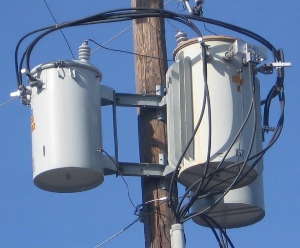
6 5 POLEMOUNT TRANSFORMERS 5.1 Ratings All ratings shall be for 60 hertz alternating current, oil immersed, self-cooled transformers capable of continuous operation at rated KVA without exceeding either a 65 o C average temperature rise or an 80 o C hot spot temperature rise The basic impulse level (BIL) shall be 95 kv. 5.2 Pressure Relief Device All transformers shall be designed such that all excessive pressure build-ups are released without damage to the tank in accordance with ANSI C All transformers shall be equipped with a pressure relief device (either Tomco Series 1776K or Qualitrol Model ). The threads shall be sealed with pipe dope. 5.3 Transformer Taps No transformer taps are required. 5.4 Transformer Oil Transformers shall be insulated with new (unused) mineral oil. The oil shall meet the requirements of ANSI C , Article (1), ANSI C and ASTM 3487 Type II. The transformer nameplate shall indicate that the PCB content of said transformer is less than 1 PPM or at time of manufacture gas chromatographic analysis certified non-detectable PCB. The oil shall be inhibited mineral oil containing 0.2 % by weight DBPC. The nameplate shall show the gallons of oil and state the oil type as Mineral Oil. 5.5 High Voltage Bushings and Terminals Transformers shall be equipped with cover-mounted, wet process porcelain high voltage bushings (two bushings) with clamp style terminals in accordance with ANSI C , Table 7. The bushings shall be light gray in color. The clamp type terminal shall be capable of being tightened with a Fargo wrench (Fargo Manufacturing, Catalog No. GP-203) High voltage bushings shall be equipped with Central Maloney Handwheel Type Wildlife Guards which are a hinged wildlife guard for use with handwheel tightened bushing terminals. Manufacturer specific part numbers allowed below: Bid No Exhibit I Page 6 of 19


7 5.6 Low Voltage Bushings and Terminals Transformers shall be equipped with side wall-mounted, low voltage bushings. Units 100 KVA and smaller shall have clamp type terminals in accordance with ANSI C , Figure 4a. Units 167 KVA and larger shall have 4-hole square spade type terminals in accordance with ANSI C , Figure 4b, Spade H Transformers of 100kVA and larger shall have a bracket centered below the secondary bushings for mounting cable supports for the secondary voltage wires Number and arrangement of low-voltage terminals shall be in accordance with ANSI C , Table Polymer secondary bushings shall be used for transformers. 5.7 Transformer Tanks Transformer tanks shall be of welded steel construction. The tank shall be a conventional, oil-filled, pole-type with only one pole-mounting position The tank covers shall have a slope of percent for moisture run-off and shall have an insulated coating on the cover capable of withstanding a minimum of 10kV at a 2000 volt/second rate of rise, tested per ASTM D149 using ¼ diameter electrodes The overall size of the transformer and the weight of the transformers, once filled with oil, shall not exceed the following: Bid No Exhibit I Page 7 of 19
8 5.7.4 Tanks shall have tank ground provisions and support lugs in accordance with ANSI Standard C Table 2: Single Phase Pole Mount Transformers Max Dimensions Size (KVA) Weight (lbs.) Height (in.) * Width (in.)** Depth (in.)*** * Height shall be measured from bottom of tank to top of primary terminal at top of primary bushing. ** Width shall be measured from lifting hook to lifting hook. *** Depth shall be measured from mounting bracket to outside of secondary terminal. 5.8 Grounding Lugs Transformers shall be furnished with a minimum of 2 ground lugs. One installed in the transformer low-voltage ground provision, and a second on the opposite side of the tank. The ground lugs shall be a Fargo (Catalog No. GC-207). 5.9 TIF and RIV Requirement TIF - Transformers shall be designed to meet REA Telephone Influence Factor (TIF) requirements, as detailed in REA Specifications D-10. Transformer I-T tests shall be made in accordance with the method described in IEEE Standard No , except as noted in REA Specifications D-10. REA Specification D-10 requires that the average overall I-T of the secondary windings per transformer nameplate KVA shall not exceed the following limits: I-T per KVA 120 Volts 132 Volts RIV - The Radio Influence Voltage (RIV) shall not (per REA Specification D-10) exceed 100 µv (average measurement) at 1 MHz measured at 110% of rated voltage in accordance with the methods outlined in ASA Publication C63.2, 1950, Appendix A, Figure 5. Dual voltage transformers shall be tested on the highest connection. Bid No Exhibit I Page 8 of 19
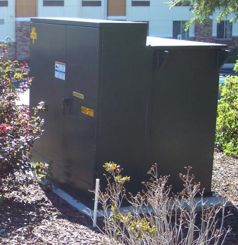
9 6 PAD MOUNT TRANSFORMER SINGLE PHASE 6.1 Ratings All ratings shall be for 60 Hertz alternating current, oil immersed, self-cooled transformers capable of continuous operation at rated KVA without exceeding either a 65 o C average temperature rise or an 80 o C hot spot temperature rise The electrical characteristics of the completely assembled high and low voltage terminals shall be in accordance with ANSI C , Table 1 and Section The basic impulse level (BIL) shall be 95 kv. 6.2 Loop Feed Transformers will be suitable for loop feed The minimum current-carrying capabilities of components for looped primary cable systems shall be 200 Amps (continuous) and 10,000 Amps rms symmetrical for 0.17 sec. (short-time current rating) for transformers with or without high-voltage switching. 6.3 Transformer Type Transformers shall be Type 2 in accordance with Figure 2a of ANSI C Pressure Relief Device All transformers shall be designed such that all excessive pressure build-ups are released without damage to the tank in accordance with ANSI C All transformers shall be equipped with a pressure relief device (either Tomco Series 1776K or Qualitrol Model ). The threads shall be sealed with pipe dope. 6.5 Transformer Taps No transformer taps are required. 6.6 High Voltage Bushings Transformers shall come equipped with two high voltage bushing wells and corresponding load break inserts for dead front application. The bushing wells shall be externally clamped, 200-amp rated, separable, and rated for primary switching per IEEE The bushings shall conform to ANSI C , Type 2 arrangement The load-break bushing inserts shall be Cooper Power Systems LBI 215 or Elastimold (Catalog No. 1601A4) Inserts shall be shipped with physically wired down & secured dust caps or use a dust cap equiped with a pressure relief hole to prevent pressure build up in the dust cap that would cause loss of the dust cap. 6.7 Low Voltage Bushings Transformers shall be equipped with fully insulated, low voltage bushings with in-line NEMA standard stud terminals in accordance with Figure 4C of ANSI C Transformers shall be furnished with the following terminals: Table 3: Single Phase Padmount Terminal Size KVA Secondary Voltage Terminal Size /120 Stud, 5/8 11 UNC-2A /120 Stud, 1 14 UNC-2A Bid No Exhibit I Page 9 of 19
10 6.8 Grounding Lugs Transformers shall be furnished with a total of 2 grounding lugs installed in the transformer highvoltage ground provision, centered near the bottom of the HV compartment and spaced horizontally 8 inches or more apart The ground lugs shall be Fargo (Catalog No. GC-207). 6.9 Compartmental Locking The terminal compartment covers shall be secured with a captive nut and a captive recessed 9/16 stainless steel or silicon bronze Pentahead bolt, and provisions for padlocking. The Pentahead bolt shall be coordinated so that it must be engaged before a padlock can be inserted into or removed from the hasp. All transformers shall meet the requirements for tamper-resistance of NEMA TR-1 and Western Underground Guide No Fusing Transformers shall be provided with Cooper Power Systems Bay-O-Net fuse holders. They shall be of the sidewall mount type with flapper, Cat. No C99FV Transformers shall be provided with Cooper Power Systems Bay-O-Net, dual sensing, load break, externally removable fuses, in series with under oil, internally mounted 8.3 kv partial range current limiting fuses (CLF). The partial range fuse shall be manufactured by Cooper Power Systems (Type ELSP) The partial range current limiting fuses shall be placed in series with the Bay-O-Net fuse holder and be mounted internally under oil. Partial range current limiting fuses shall have a nominal voltage rating of 8.3kV Oil drip shields shall be provided designed to catch and hold oil. Oil drip shields that redirect oil rather than catch and hold it will not be allowed The Bay-O-Net Fuse size and type for each voltage shall be painted on the inside of the primary side cabinet door utilizing yellow characters one (1) inch high. In addition, the bayonet and current limiting fuse part numbers will be displayed on the nameplate. Fuses shall meet the District s current fusing specifications which are shown in the table below Dual Voltage Units shall be delivered with fusing according to the lower voltage and include Bay- O-Net fuses for the higher voltage. Bid No Exhibit I Page 10 of 19
11 Table 4: 7.2 kv Single Phase Transformer Fusing Stock # KVA Bay-O-Net Fuse (Dual Sensing) Continuous Rating (A) C03M 3 Current Limiting (ELSP Backup) A01M (Isolation Link only) ELSP Rating (A) C05M 8 CBUC08040C C08M 15 CBUC08080C C10M 25 CBUC08125C C10M 25 CBUC08125C C12M 50 CBUC08165D na Table 4b: 2.4 kv Single Phase Transformer Fusing Stock # KVA Bay-O-Net Fuse (Dual Sensing) Continuous Rating (A) Current Limiting (ELSP Backup) ELSP Rating (A) C08M 15 CBUC08065C C10M 25 CBUC08100C C12M 50 CBUC08150D C12M 50 CBUC08165D C14M 65 CBUC08165D100* C03CB 65 CBUC08165D100* C04CB 100 CBUC08250D100* 500 * Two fuses in parallel Bid No Exhibit I Page 11 of 19
12 6.11 Transformer Tanks Transformer tanks shall be constructed in accordance with ANSI C The primary and secondary bushing compartment shall have a hinged, vertical-swing cover. Both the cover and the tank shall be domed or sloped to prevent moisture collection The cover hinge pins and the threaded lifting inserts shall be stainless steel Grounding provisions shall consist of two grounding lugs, centered near the bottom of the HV compartment of the transformer and spaced horizontally 8 inches or more apart. The tapped holes shall be plugged during painting to prevent coating of the threads Drain and fill plugs shall be bronze, cadmium, or stainless steel. No galvanized hardware will be acceptable. Drain and fill plugs will be sealed with pipe dope Drain and fill plugs shall be a threaded plug, not a cap, to minimize interference with anything inside the HV or LV compartments The overall maximum transformer size shall be within the following dimensional ranges: Table 5: Single Phase Transformers - Tank Sizes Size (KVA) Height (in.) * Width (in.) ** Depth (in.) *** Compartment Minimum Terminal Depth (in.) **** max. 31 min. 36 max. 40 max 15 < max 26 max 29 max 15 * Height shall be measured from top of highest point to bottom of unit. ** Width shall be measured from left to right, when facing the lid, across widest part of unit. *** Depth shall be measured from lid to rear, across deepest part of unit. **** Depth shall be measured from lid to front of bushing well wall. Bid No Exhibit I Page 12 of 19
13 7 PAD-MOUNTED TRANSFORMERS THREE PHASE 7.1 Ratings All ratings shall be for 60 Hertz alternating current, oil immersed, self-cooled transformers capable of continuous operation at rated KVA without exceeding either a 65 o C average temperature rise or an 80 o C hot spot temperature rise The electrical characteristics of the completely assembled high and low voltage terminals shall be in accordance with IEEE C , Table 3 and Table The basic impulse level (BIL) shall be 95 kv. 7.2 Transformer Type Transformers shall be loop feed construction, in accordance with Figure 2 of IEEE C Core Construction The core shall be either triplex or five-legged construction. 7.4 Pressure Relief Device All transformers shall be designed such that all excessive pressure build-ups are released without damage to the tank in accordance with IEEE C All transformers shall be equipped with a pressure relief device (either Tomco Series 1776K or Qualitrol Model ). The threads shall be sealed with pipe dope. 7.5 Transformer Taps No transformer taps are required. 7.6 High Voltage Bushings Transformers shall come equipped with high voltage bushing wells and corresponding load break inserts for dead front application. The bushing wells shall be externally clamped, 200-amp rated, separable, and rated for primary switching per IEEE The load-break bushing inserts shall be Cooper Power Systems (Catalog No. LBI 215 or Elastimold (Catalog No. 1601A4) The primary neutral shall be insulated and no H 0 bushing provided on Y- transformers Inserts shall be shipped with physically wired down & secured dust caps or use a dust cap equiped with a pressure relief hole to prevent pressure build up in the dust cap that would cause loss of the dust cap. 7.7 Low Voltage Bushings Transformers shall be equipped with fully insulated, low voltage bushings, in accordance with Fig. 8(a) of IEEE C Transformers shall be furnished with the following NEMA standard stud or spade terminals as per IEEE C Fig. 9. Bid No Exhibit I Page 13 of 19
14 Table 6: Three Phase Padmount Transformers Terminal Sizes KVA Secondary Voltage Terminal Size Y/277 Stud, 5/8 11 UNC 2A (Fig. 9d) , 208Y/ , 208Y/ Y/ Y/ Y/ Y/ Y/277 Stud, 1 14 UNC 2A With 6 hole Spade (Fig. 9d) Spade, 6 hole - (Fig. 9b) Spade, 10 hole - (Fig. 9c) Ten-hole spade pads shall be furnished with additional support, as designed by the manufacturer. The supports shall be attached to the pads at the farthest point from the tank wall and attached in a manner so as to not interfere with the use of any of the pad s holes On 750kVA and larger, a galvanized shackle shall be installed beneath each bushing for the purpose of hanging a cable grip support. 7.8 Grounding Lugs Transformers shall be furnished with a total of 4 ground lugs: two ground lug installed in the transformer low-voltage ground provision and two ground lugs installed in the transformer highvoltage ground provision The ground lugs shall be Fargo (Catalog No. GC-207) Each compartment s ground lugs shall be installed three inches from the compartment wall, one on each side of the compartment. 7.9 Compartmental Locking All hinged or removable cabinet access lids or doors shall have a three point latch and be provided with a 9/16 stainless steel or silicon bronze Pentahead captive bolt locking device and provisions for padlocking. The Pentahead bolt shall be coordinated so that it must be engaged before a padlock can be inserted into or removed from the hasp. All transformers shall meet the requirements for tamper-resistance of NEMA TR-1 and Western Underground Guide No Hand Holes A bolted on tank hand hole shall be secured against tampering by some means accessible only from the inside of the compartment Fusing Transformers shall be provided with Cooper Power Systems Bay-O-Net fuse holders. They shall be of the sidewall mount type with flapper, Cat. No C99FV Transformers shall be provided with Cooper Power Systems Bay-O-Net, dual sensing, load break, externally removable fuses. They shall also be provided with internally mounted partial range current limiting fuses (CLF) manufactured by Cooper Power Systems. Bid No Exhibit I Page 14 of 19
15 The partial range current limiting fuses (type ELSP) shall be placed in series with the Bay-O-Net fuse holder and be mounted internally under oil. Partial range current limiting fuses shall have a nominal voltage rating of 8.3kV Oil drip shields shall be provided with the Bay-O-Net fuse holder and be designed to catch and hold oil. Oil drip shields that redirect oil rather than catch and hold it will not be allowed The Bay-O-Net Fuse size and type for each voltage shall be painted on the inside of the primary side cabinet door utilizing yellow characters one (1) inch high. In addition, the bayonet and current limiting fuse part numbers will be displayed on the nameplate. Fuses shall meet the District s current fusing specifications which are shown in the table below Dual Voltage Units shall be delivered with fusing according to the lower voltage and include Bay- O-Net fuses for the higher voltage. Table 7: kv Three Phase Transformer Fusing Stock # Three Phase KVA Bay-O-Net Fuse (Dual Sensing) Continuous Ampere Rating Current Limiting (ELSP Backup) ELSP Ampere Rating C05M 8 CBUC15030C C08M 15 CBUC15080C C10M 25 CBUC15100C C12M 50 CBUC15150D C14M 65 CBUC15125C100* C14M 65 CBUC15125C100* C04CB 100 CBUC15125C100* C05CB 125 CBUC15125C100* C05CB 125 CBUC15125C100* 250 Table 7b: 4.16 kv Three Phase PAD Transformer Fusing Stock # KVA Bay-O-Net Fuse (Dual Sensing) Continuous Rating (A) Current Limiting (ELSP Backup) ELSP Rating (A) C08M 15 CBUC15080C C10M 25 CBUC15125C C12M 50 CBUC15165D C12M 50 CBUC15165D C14M 65 CBUC15150D100* C14M 65 CBUC15150D100* C04CB 100 CBUC15180D100* C05CB 125 CBUC15180D100* 360 * Two fuses in parallel Bid No Exhibit I Page 15 of 19
16 7.12 Transformer Tanks Transformer tanks shall be constructed in accordance with IEEE C Grounding provisions shall consist of 4 grounding pads, two on the HV compartment and two on the LV compartment side of the transformer. The tapped holes shall be plugged during painting to prevent coating of the threads Drain and fill plugs shall be bronze, cadmium, or stainless steel. No galvanized hardware will be acceptable. Drain and fill plugs will be sealed with pipe dope Drain and fill plugs shall be a threaded plug, not a cap, to minimize interference with anything inside the HV or LV compartments For transformers 300 kva and larger, the front cabinet apparatus compartment shall have side panels that open, extend, and lock allowing side entry to termination compartments and less restricted space For transformers 300 kva and larger, Roof sections shall be able to be raised to allow vertical cable pulling / support Oil Drain Valve Transformers shall come equipped with an oil drain valve installed at the bottom edge in the transformer secondary compartment, ¾ minimum diameter, gate or ball activated The threads shall be sealed with pipe dope Labeling A danger label, complying with ANSI Z535, shall be located on the inside of the transformer and readily visible whenever the first equipment door is open Accessories In addition to standard accessories, each transformer 1500 KVA and larger shall be properly equipped with the following gauges mounted in the low voltage compartment Oil Level Gauge Dial thermometer with maximum top oil temperature indicator and magnetic reset Tank Pressure Vacuum Gauge Tank Dimensions The maximum dimensions of the 3 phase Padmount transformers shall be as shown below. These dimensions do not include cooling fins. Table 8: Three Phase Transformers Maximum Dimensions 75 KVA Mini-Pad 150 to 500 KVA 750 to 2500 KVA Height 42 max 70 max 89 max Width 44.5 max 72 max 88 max Depth 42 max 62 max 66 max Depth of Apparatus Compartment - The minimum depth of the apparatus compartment (except 75KVA mini-pad) shall be 24 inches, as shown in Dimension F of Figure 7 of IEEE Standard C Cooling Fins - Cooling fins shall not extend further than 12 inches beyond the dimensions shown above. Bid No Exhibit I Page 16 of 19
17 8 TRANSFORMER OIL 8.1 Transformers shall be insulated with new (unused) mineral oil. The oil shall meet the requirements of ANSI C , Article (1), ANSI C and ASTM 3487 Type II. The transformer nameplate shall indicate that the PCB content of said transformer is less than 1 PPM or at time of manufacture gas chromatographic analysis certified non-detectable PCB. The oil shall be inhibited mineral oil containing 0.2 % by weight DBPC. The nameplate shall show the gallons of oil. 9 NOISE 9.1 Transformer sound levels shall not exceed the values specified in the latest revision of NEMA Publication TR PAINT FINISH 10.1 The transformer shall have a corrosion resistant finish that shall be capable of meeting the functional specifications or exceed paint requirements of ANSI C , latest revision. The outside shall be properly prepared, primed and painted with highly weather resistant finish coat. All transformers shall have the manufacturer s premium paint system Transformers shall be given a phosphatizing bath, or sand blasted, grit blasted or shot blasted, then primed with epoxy or vinyl primer. Transformers shall have a corrosion resistant finish that shall be capable of meeting the functional specifications or exceed ANSI c The exterior finish coat shall meet or exceed the following: be semi-gloss polymer, free of runs and sags, primed with a primer, no less than 2.0 mils dry thickness and a coat of semi-gloss polymer type enamel paint no less than one (1) mil dry thickness (total measured thickness 3 mils) Pole Mounted Transformers the finish coat shall be semi-gloss sky gray similar in color to ANSI Standard no. 70. The transformer top shall meet or exceed the following: have at least 10 mils of paint. The transformer sides and bottom shall have at least 3 mils of paint. The inside of the transformer shall have at least 3 mils of paint from a point 2 inches below the oil level up to and including the top. Complete painting of the inside is acceptable Pad Mounted Transformers - the finish coat shall be semi-gloss olive-green gray similar to Munsel no. 7GY3.29/1.5. The interior cabinet surfaces shall be primed and finished, with no less than 2.0 mils dry thickness 10.5 NAMEPLATES Nameplates shall be made of stainless steel or anodized aluminum and permanently marked with essential operating data meeting ANSI standard c for nameplate b The transformer nameplate shall specifically state that the transformer is filled with Mineral Oil and the number of gallons of oil it contains Nameplate impedance must be within ±10% of the actual tested impedance on all units The nameplate shall indicate that the PCB content of said transformer is less than 1 ppm or that at the time of manufacture gas chromatographic analysis certified non-detectable PCB Each nameplate shall contain a transformer bar code. The bar code label shall meet all requirements of IEEE standard c The bayonet and current limiting fuse part numbers will be displayed on the nameplate for all Padmount units Nameplates shall be mechanically fastened with rivets, bolts, or screws. Glue, adhesives, or double sided tape are not acceptable. Bid No Exhibit I Page 17 of 19
18 11 INSPECTION 11.1 The purchaser shall at any reasonable time be permitted to have a representative visit the Contractor s factory for the purpose of witnessing manufacture of the transformers to ascertain if the material and process used in the manufacturing conform to the Specifications. 12 TESTS 12.1 Each transformer shall receive complete tests at the factory in accordance with latest ANSI standards. At the option of the district, transformers may be tested for acceptance upon receipt All transformers manufactured under this specification shall be tested for core and winding (copper) losses at 85 o C, percent impedance at 85 o C, and exciting current (100% voltage and subjected to a full wave voltage impulse). Actual loss data shall be prepared in accordance with the bid form Vendor shall supply verification that the design has passed short circuit criteria per ANSI C and c latest revision Guaranteed losses: the losses submitted by the bidder for bid evaluation shall be considered as guaranteed losses by the district. DOE efficiencies will be calculated off of these quoted losses Certified test reports shall be furnished to the district at time of delivery or invoicing of transformers. Invoices must reference serial number of transformer, bid item and quoted losses. No payment will become due until proper serial numbers and the corresponding certified test reports are received by the district. 13 WORKMANSHIP, MATERIAL, AND FINISH 13.1 All workmanship and material used on the equipment shall be first class, the best of their respective kinds and shall be in full accordance with the most modern manufacturing practices for distribution transformers. 14 DELIVERY METHODS 14.1 Destination The transformers shall be shipped f.o.b. destination to 1150 Hawley Street, Wenatchee, WA The delivery will be accepted Monday through Friday between the hours of 9:00 am and 2:00 pm. No delivery of transformers will be accepted on holidays. Please call the Hawley Street Warehouse Forman at (509) , ext. 4730, 24 hours prior to delivery. No transformers will be received on national holidays Methods Polemount transformers shall be filled with the proper amount of transformer oil and shipped, completely assembled, in an enclosed van Padmount transformers rated up to 300 KVA shall be shipped on individual pallets made with 4 by 4 lumber minimum (one transformer per pallet) and securely attached to the pallets to facilitate handling with forklift and shipped, completely assembled, in an enclosed van Padmount transformer rated KVA shall be capable of being unloaded with an overhead crane (skids are not required on these sizes) and must be shipped on flatbed trailers and tarped or otherwise protected from the elements during shipping Rejection Of Shipment Transformers exhibiting damaged parts, broken securing devices, or are dirty from lack of proper shipping, shall be cause for rejection of shipment. Bid No Exhibit I Page 18 of 19
19 Bid No Exhibit I Page 19 of 19
A. Three-phase, oil filled self-cooled, padmounted transformers are installed outdoors on pads in the EWEB distribution system.
 1. APPLICATION A. Three-phase, oil filled self-cooled, padmounted transformers are installed outdoors on pads in the EWEB distribution system. 2. REFERENCE STANDARDS A. The transformers supplied shall
CLARK PUBLIC UTILITIES TECHNICAL SPECIFICATIONS THREE-PHASE PADMOUNTED TRANSFORMERS
 CLARK PUBLIC UTILITIES TECHNICAL SPECIFICATIONS THREE-PHASE PADMOUNTED TRANSFORMERS Originated 1/85 Revised 6/95 Revised 6/02 Revised 11/05 Revised 4/08 Revised 11/09 Revised 1/12 Revised 11/12 Revised
CLARK PUBLIC UTILITIES TECHNICAL SPECIFICATIONS THREE-PHASE PADMOUNTED TRANSFORMERS
 CLARK PUBLIC UTILITIES TECHNICAL SPECIFICATIONS THREE-PHASE PADMOUNTED TRANSFORMERS Originated 1/85 Revised 6/95 Revised 6/02 Revised 11/05 Revised 4/08 Revised 11/09 Revised 1/12 Revised 11/12 Revised
SPECIFICATION FOR THREE-PHASE PAD MOUNT TRANSFORMERS. D. Dead Front, loop feed design shall be employed.
 City of Cartersville Electric System P.O. Box 1390 320 S. Erwin St. Cartersville, GA 30120 770-387-5631 March 2006 SPECIFICATION FOR THREE-PHASE PAD MOUNT TRANSFORMERS This specification provides standardization
CITY OF LOMPOC UTILITIES DEPARTMENT ELECTRICAL DIVISION SPECIFICATION NO. ELE-115
 CITY OF LOMPOC UTILITIES DEPARTMENT ELECTRICAL DIVISION SPECIFICATION NO. ELE-115 PADMOUNTED TRANSFORMERS 12kV AND DUAL VOLTAGE, RADIAL FEED STAINLESS STEEL NOVEMBER 2011 Specification:ELE_115_R1 Page
Single-Phase Step Voltage Regulator
 Single-Phase Step Voltage Regulator - Overhead Mounted - Page 1 of 12 Table of Contents 1 GENERAL... 3 2 CONSTRUCTION... 3 3 RIV REQUIREMENT... 7 4 REGULATOR CONTROLS... 7 5 TESTS... 9 6 EVALUATION...
SECTION PADMOUNT TRANSFORMER - OIL FILLED
 SECTION 26 12 19.01 PADMOUNT TRANSFORMER - OIL FILLED PART 1 GENERAL 1.1 DESCRIPTION: Padmount Transformers and Insulating Oil with underground primary and secondary connections for use in distribution
MATERIAL SPECIFICATION ELECTRIC OPERATIONS ORGANIZATION. M3902 ****Supercedes BECo Standard E and ComElectric Spec ****
 Page 1 of 8 ****Supercedes BECo Standard E2.12-2.12 and ComElectric Spec 6-0895**** 1.0 General Requirements SINGLE PHASE PAD-MOUNTED DISTRIBUTION TRANSFORMERS 1.1 These specifications cover single-phase
MATERIAL STANDARD ELECTRIC OPERATIONS ORGANIZATION. ****Supercedes BECo Standard E and ComElectric Spec ****
 Page 1 of 8 ****Supercedes BECo Standard E2.12-2.14 and ComElectric Spec 7-0895**** THREE-PHASE DEADFRONT PAD-MOUNTED DISTRIBUTION TRANSFORMERS, LOOP & RADIAL FEED DESIGNS 1.0 General Requirements 1.1
GENERAL INFORMATION POLE MOUNT TRANSFORMER SINGLE PHASE PAD MOUNT TRANSFORMER SINGLE PHASE POLE MOUNT TRANSFORMER THREE PHASE 17
 GENERAL INFORMATION SECTION GUIDE SECTION 10 PAGE 1 DESCRIPTION SECTION NUMBER GENERAL INFORMATION... 10 POLE MOUNT TRANSFORMER SINGLE PHASE... 15 PAD MOUNT TRANSFORMER SINGLE PHASE..... 16 POLE MOUNT
SPECIFICATION FOR THREE PHASE PAD-MOUNT DISTRIBUTION TRANSFORMERS
 SPECIFICATION T-5 SPECIFICATION FOR THREE PHASE PAD-MOUNT DISTRIBUTION TRANSFORMERS 1.0 GENERAL PURPOSE 1.1 These specifications cover the electrical and mechanical features of a three phase, 60 hertz,
C. System Design and Performance Requirements
 Change History Date Description of Change Pages / Sections Modified 6/15/16 Updated division section from 16361-E-E to 26 10 03, removed references to other section numbers A. Summary - mgl44 Change Approver
Three-Phase Pole Mounted Recloser
 Three-Phase Pole Mounted Recloser Page 1 of 8 Table of Contents 1 GENERAL... 3 2 CONSTRUCTION... 3-5 3 BUSHINGS... 5 4 LINE CONNECTOR... 5 5 TOOLS....5 6 NAMEPLATES..6 7 PAINT... 6 8 EXTERNAL HARDWARE
15-kV Wall-Mount Switchgear Three-Phase Indoor/Outdoor 600 Amp S&C Mini-Rupter Switch
 Page 1 2015 Kinked roof prevents standing moisture Glass reinforced barriers meet NEMA GPO-3 Standards 0.625" diameter copper ground bar Elliott air-insulated bushings accept IEEE Standard inserts and
35-kV Safefront SuperWell Mini-Switch Source Isolated Pad-Mounted Switchgear 50 Amp (Max) Clip-Mounted Current Limiting Fuses
 Clip-Mounted Current Limiting Fuses") Page 1 2016 EPMR-35-311S-R2/ESW-CM9 Three Phase Two Ways per Phase 200 Amp 35 kv Class Eaton s CPS LRTPs 50 Amp (Max) 27 kv Clip-Mounted NX Fuse Provisions 21.1/36.6 kv Grounded Wye Max Design, 150 kv
Page 1 2016 EPMR-35-311S-R2/ESW-CM9 Three Phase Two Ways per Phase 200 Amp 35 kv Class Eaton s CPS LRTPs 50 Amp (Max) 27 kv Clip-Mounted NX Fuse Provisions 21.1/36.6 kv Grounded Wye Max Design, 150 kv
SERIES 802 / 812 SPECIFICATION 15KV & 25KV PADMOUNTED LIQUID-INSULATED VACUUM LOAD INTERRUPTERS AND FUSE ASSEMBLIES
 SERIES 802 / 812 SPECIFICATION 15KV & 25KV PADMOUNTED LIQUID-INSULATED VACUUM LOAD INTERRUPTERS AND FUSE ASSEMBLIES MANUALLY OPERATED / REMOTELY OPERATED DEAD FRONT PADMOUNTED SWITCHGEAR WITH VACUUM LOAD
Guide Specification. Three-Phase Solid Dielectric Trident-SR with SafeVu Integral Visible Break
 Part 1-GENERAL 1.1 DESCRIPTION Guide Specification Three-Phase Solid Dielectric Trident-SR with SafeVu Integral Visible Break The switchgear shall consist of magnetically actuated solid dielectric insulated
15-kV Live Terminal 600 Amp Group Operated Pad-Mounted Metal-Enclosed Outdoor Switchgear 140 Amp (Max) Clip Mount Current-Limiting Fuses
 Clip Mount Current-Limiting Fuses") Page 1 2015 Heavy duty 11-gauge steel enclosure is all-welded construction for long life Corrosion proof nameplate is located to provide easy access for the operator Glass reinforced barriers meet NEMA
Page 1 2015 Heavy duty 11-gauge steel enclosure is all-welded construction for long life Corrosion proof nameplate is located to provide easy access for the operator Glass reinforced barriers meet NEMA
Drive Duty Transformer Specification Virginia Transformer Corp. Power Up! Selecting the Right Transformer
 Drive Duty Transformer Specification Virginia Transformer Corp. Power Up! Selecting the Right Transformer This document contains sample specifications for Liquid-Filled Type Drive Transformers You may
SUBSTATION VACUUM CIRCUIT BREAKER (38KV)
") SUBSTATION VACUUM CIRCUIT BREAKER (38KV) For more than four decades, Myers Power Products has led the switchgear market in quality for the electric industry, delivering highly reliable products for utilities
SUBSTATION VACUUM CIRCUIT BREAKER (38KV) For more than four decades, Myers Power Products has led the switchgear market in quality for the electric industry, delivering highly reliable products for utilities
SUBSTATION VACUUM CIRCUIT BREAKER (25.8 / 27KV)
") SUBSTATION VACUUM CIRCUIT BREAKER (25.8 / 27KV) For more than four decades, Myers Power Products has led the switchgear market in quality for the electric industry, delivering highly reliable products
SUBSTATION VACUUM CIRCUIT BREAKER (25.8 / 27KV) For more than four decades, Myers Power Products has led the switchgear market in quality for the electric industry, delivering highly reliable products
SUBSTATION VACUUM CIRCUIT BREAKER (15.5KV)
") SUBSTATION VACUUM CIRCUIT BREAKER (15.5KV) For more than four decades, Myers Power Products has led the switchgear market in quality for the electric industry, delivering highly reliable products for utilities
SUBSTATION VACUUM CIRCUIT BREAKER (15.5KV) For more than four decades, Myers Power Products has led the switchgear market in quality for the electric industry, delivering highly reliable products for utilities
1500 kva Pad Mount Transformer GRDY/14400V Primary - 208Y/120 Wye Secondary - Oil Cooled
 1500 kva Pad Mount Transformer - 24940GRDY/14400V Primary - 208Y/120 Wye Secondary - Oil Cooled Part #: MT-PMO-3P-24940GRDY.14400-1500KVA-208Y.120-N3R Page: 1 The MT-PMO-3P-24940GRDY.14400-1500KVA-208Y.120-N3R
Michigan State University Construction Standards SECONDARY UNIT SUBSTATIONS PAGE
 PAGE 261116-1 SECTION 261116 PART 1 - GENERAL 1.1 RELATED DOCUMENTS A. Drawings and general provisions of the Contract, including General and Supplementary Conditions and Division 01 Specification Sections,
CITY OF LOMPOC UTILITIES DEPARTMENT ELECTRICAL DIVISION SPECIFICATION NO. ELE-112 SUBSTATION CLASS VACUUM CIRCUIT BREAKERS OCTOBER 2008
 CITY OF LOMPOC UTILITIES DEPARTMENT ELECTRICAL DIVISION SPECIFICATION NO. ELE-112 SUBSTATION CLASS VACUUM CIRCUIT BREAKERS OCTOBER 2008 SPECIFICATION NO: ELE_112_R1.doc Page 1 of 3 Rev. 10/28/2008 SPECIFICATION
Distribution Transformers
 Distribution Transformers PEAK Three-Phase Pad-mounted Compartmental Type Functional Specification Guide Functional Specification for Three-Phase Pad-Mounted PEAK Distribution Transformers 45 10,000 kva
35-kV Safefront 200 Amp SuperWell Primary Metering Station Pad-Mounted Outdoor
 35-kV Safefront 2 Amp SuperWell 5-33 Page 1 216 EPM-PMS-35-311P-R2/ESW Three Phase Two Ways per Phase 2 Amp 35 kv Class Eaton's CPS LRTPs NEMA Standard Outdoor Instrument Transformer Provisions 21.1/36.6
Distribution Transformers
 Distribution Transformers Three-Phase Pad-Mounted Compartmental Type Functional Specification Guide Functional Specification for Three-Phase Pad-Mounted Distribution Transformers 45 10,000 kva 1.0 Scope
Underground Distribution Switchgear
 Underground Distribution Switchgear Functional Specification Guide Functional Specification for 15 kv, 25 kv, or 35 kv Underground Distribution Switchgear 1. Scope 1.1. This specification applies to three-phase,
Technical Specification for Pole Mounted Capacitor Rack
 Technical Specification for Pole Mounted Rack Page 1 1. Scope and Function a) Pole mounted capacitor racks shall be installed on a distribution feed as an economical means of applying capacitor units to
TECHNICAL SPECIFICATIONS OIL FILLED PADMOUNTED THREE PHASE WYE-WYE TRANSFORMERS
 TECHNICAL SPECIFICATIONS OIL FILLED PADMOUNTED THREE PHASE WYE-WYE TRANSFORMERS I. GENERAL This specification covers three phase wye-wye padmounted transformers and is used in conjunction with the Specifications
35-kV Safefront Mini-Switch Source Isolated Pad-Mounted Switchgear 50 Amp (Max) Clip-Mounted Current-Limiting Fuses
 Clip-Mounted Current-Limiting Fuses") Page 1 2016 Heavy duty 11-gauge steel enclosure is all-welded construction for long life 11-gauge steel equipment plate is rigid for easier elbow operation Parking stands for the upper two phases extend
Page 1 2016 Heavy duty 11-gauge steel enclosure is all-welded construction for long life 11-gauge steel equipment plate is rigid for easier elbow operation Parking stands for the upper two phases extend
Solid Dielectric Load Break Switch SPECIFICATION. 25kV, 630A, 4 WAYS, 4 WAYS SWITCHED PADMOUNTED VACUUM LOAD INTERRUPTER
 Solid Dielectric Load Break Switch SPECIFICATION 25kV, 630A, 4 WAYS, 4 WAYS SWITCHED PADMOUNTED VACUUM LOAD INTERRUPTER MANUALLY OPERATED / REMOTELY OPERATED DEAD FRONT PADMOUNTED VACUUM LOAD INTERRUPTING
Fixed, Medium-Voltage, Pad-Mounted, Three-Phase Power Capacitor Bank Guide Form Specification
 Fixed, Medium-Voltage, Pad-Mounted, Three-Phase Power Capacitor Bank Guide Form Specification 1. General 1.1 This specification is for a fixed, medium-voltage, padmounted, three-phase power capacitor bank
15-kV Safefront 200 Amp Primary Capacitor Station Pad-Mounted Outdoor
 Page 1 2015 Heavy-duty 11-gauge steel enclosure is all-welded construction for long life Clear polycarbonate removable safety barrier separates upper and lower compartment (supplied only with internally
35-kV Safefront 200 Amp SuperWell Primary Capacitor Station Pad-Mounted Outdoor
 Page 1 2016 EPM-PCS-35-320P-R2/ESW-GCM6-2S-SA Three Phase Two Ways per Phase 200 Amp 35 kv Class Eaton's CPS LRTPs 35 kv Elliott Air-Insulated SuperWell Bushings 21.1/36.6 kv Grounded Wye Max Design, 150
Automatic, Medium-Voltage, Pad-Mounted, Three-Phase Power Capacitor Bank Guide Form Specification
 Automatic, Medium-Voltage, Pad-Mounted, Three-Phase Power Capacitor Bank Guide Form Specification 1. General 1.1 This specification is for an automatic, medium-voltage, padmounted, three-phase power capacitor
15-kV Safefront Mini-Switch Source Isolated Pad-Mounted Switchgear 140 Amp (Max) Clip-Mounted Current-Limiting Fuses
 Clip-Mounted Current-Limiting Fuses") Page 1 2016 Heavy duty 11-gauge steel enclosure is all-welded construction for long life 200 Amp Elliott air-insulated bushing wells accept IEEE Standard inserts and elbows ushing wells may be added or
Page 1 2016 Heavy duty 11-gauge steel enclosure is all-welded construction for long life 200 Amp Elliott air-insulated bushing wells accept IEEE Standard inserts and elbows ushing wells may be added or
CENTER BREAK GROUP OPERATED AIR BREAK SWITCHES RATED 15.5kV THROUGH 170kV EFFECTIVE DATE: 10/25/16 REV B
 CENTER BREAK GROUP OPERATED AIR BREAK SWITCHES RATED 15.5kV THROUGH 170kV EFFECTIVE DATE: 10/25/16 REV B TCV2 Hubbell has a policy of continuous product improvement. Please visit hubbellpowersystems.com
CITY OF MARYVILLE ELECRIC DEPARTMENT Maryville, Tennessee SPECIFICATIONS FOR 15KV POWER CIRCUIT BREAKERS. September 2018
 CITY OF MARYVILLE ELECRIC DEPARTMENT Maryville, Tennessee SPECIFICATIONS FOR 15KV POWER CIRCUIT BREAKERS September 2018 Myrick Clinton Cannon TN P.E. #112337 Patterson & Dewar Engineers, Inc. P. O. Box
Solid Dielectric, Single Phase Reclosers
 Solid Dielectric, Single Phase Reclosers Providing electronic overcurrent protection for single phase operation on systems rated through 38kV, 800A continuous current,12.5ka symmetrical interrupting Reliable
Product Specifications for Phase Over Phase GOABS(r)
") 1. General a) This specification covers the design, manufacture, and shipment of phase-over-phase, 1-way, 2-way, 3-way, and 4-way, gang-operated disconnecting switches, both air-break and load-break, for
1. General a) This specification covers the design, manufacture, and shipment of phase-over-phase, 1-way, 2-way, 3-way, and 4-way, gang-operated disconnecting switches, both air-break and load-break, for
100 / 110 DRYWELL FUSE SPECIFICATION
 100 / 110 DRYWELL FUSE SPECIFICATION 15KV & 25KV SUBMERSIBLE VACUUM LOAD INTERRUPTERS AND DRYWELL FUSE ASSEMBLIES MANUALLY OPERATED / REMOTELY OPERATED SUBMERSIBLE SWITCHGEAR WITH LOAD INTERRUPTING SWITCHES
Figure 1. Two and Three-phase MagneX.
 Fusing Equipment Two- & Three-Phase MagneX Interrupter Electrical Apparatus 240-33 GENERAL The Cooper Power Systems MagneX Interrupter is an overcurrent protective device that protects distribution transformers
Technical Specification For Outdoor Substation Harmonic Filter Banks
 Technical Specification For Outdoor Substation Harmonic Filter Banks One of Three 5th, 11th & 23rd, 34.5 kv, Rated Harmonic Filter Assemblies Provided for a Central Venezuela Heavy Oil Production Field
Medium Voltage Standby non-paralleling Control GUIDE FORM SPECIFICATION
 Medium Voltage Standby non-paralleling Control 1. GENERAL GUIDE FORM SPECIFICATION A. The requirements of the contract, Division 1, and part 16 apply to work in this section. 1.01 SECTIONS INCLUDE A. Medium
Product Specifications for Aluminum Vertical Break Switches
 1. General a) This specification covers the design, manufacture, and shipment of aluminum vertical break switches, both air-break and load-break configurations, for substation and transmission switching
NEW Solutions for Underground System Growth
 NEW Solutions for Underground System Growth Cooper s Single-Phase Voltage Regulator Improved Power Quality More Economical Improved System Reliability Increased Safety Better Aesthetics Lower Maintenance
C1000 Series Automatic Cap Bank
 C1000 Series Automatic Cap Bank Metal Enclosed - Medium Voltage Capacitors Assemblies Fixed / Auto Medium Voltage 5, 15, 25 and 35 kv Class Customized to your specifications The Reactive Power Solution
Solid Dielectric, Single Phase Recloser
 Solid Dielectric, Single Phase Recloser Catalog O-vsp17 Viper-SP Viper-SP solid dielectric, single phase recloser combines the time-proven reliability of electronically controlled, vacuum fault interrupters
43-SDMS-01 SPECIFICATIONS FOR
 SPECIFICATIONS FOR MV SHUNT POWER CAPACITOR BANK UP TO 36 KV This specification is property of SEC and subject to change or modification without any notice CONTENTS Clause Description Page 1.0 SCOPE 3
15-kV Live Terminal Primary Metering Station Pad-Mounted Outdoor
 ulletin Page 1 2015 Cross-kinked roof prevents standing moisture Metering Transformer compartment label is visible with doors closed Heavy duty 11-gauge steel enclosure is all-welded construction for long
Specification Pad-Mounted Capacitor Bank with Dual Fusing Integral Load-Interrupter on Line-Side Fuse Mountings
 Page 1 Specification Pad-Mounted Capacitor Bank with Dual Fusing Integral Load-Interrupter on Line-Side Fuse Mountings I. General This specification covers the design requirements for a pad-mounted capacitor
Underground Distribution Switchgear
 Underground Distribution Switchgear Functional Specification Guide Functional Specification for 15 kv, 25 kv, or 35 kv Underground Distribution Switchgear 1. Scope 1.1. This specification applies to three-phase,
500 kva Pad Mount Transformer V Delta Primary - 208Y/120 Secondary - NEMA 4X - Oil Cooled
 500 kva Pad Mount Transformer - 12470V Delta Primary - 208Y/120 Secondary - NEMA 4X - Oil Cooled Part #: MT-PDO-SS-3P-12.47KV-500KVA-208Y.120-FR3-CU Page: 1 The MT-PDO-SS-3P-12.47KV-500KVA-208Y.120-FR3-CU
35-kV Safefront 200 Amp Primary Metering Station Pad-Mounted Outdoor
 ulletin Page 1 2016 Heavy duty 11-gauge steel enclosure is all-welded construction for long life 11-gauge steel equipment plate is rigid for easier elbow operation Upper parking stands extend 3" per IEEE
Design Standard. Purpose: Design Standard:
 Design Standard Purpose: This design standard has the purpose of creating a consistent application of motor-control centers throughout the East Side Union High School District, therefore achieving a standard
1TSF /CD Attachment B. City and County of San Francisco Office of Contract Administration
 1TSF14000167/CD LINE ITEM 1: 37,5 KVA 1 PHASE PAD MOUNTED TRANSFORMER, ENVIROTEMP FR3 37.5 KVA, 10 Pad Mounted Transformer, AIMS! TYPE 2 SHRUBLINE insulating fluid 12470 Deita Two position ioadbreak switch
Padmount. Small Power Transformers 2500 kva Through 20,000 kva 5 kv Through 46 kv Primary Voltage 120V Through 25 kv Secondary Voltage
 Padmount Small Power Transformers 2500 kva Through 20,000 kva 5 kv Through 46 kv Primary Voltage 120V Through 25 kv Secondary Voltage ABB s Padmounted Transformers provide tamper-resistant protection in
34-SDMS-01 SPECIFICATIONS FOR
 SPECIFICATIONS FOR M V DROPOUT FUSE CUT OUTS This specification is property of SEC and subject to change or modification without any notice CONTENTS C l a u s e s: Page No. 1- SCOPE 3 2- CROSS REFERENCES
Section SWITCHBOARDS. Introduction. Part 1 - General. Related Work
 Section 16435 - SWITCHBOARDS Introduction Part 1 - General Related Work Section 16070 Seismic Anchorage and Restraint Section 16075 Electrical Identification Section 16080 Power Distribution Acceptance
SUBSTATION TYPE TRANSFORMER - MINERAL OIL FILLED THREE PHASE OISC 65 C RISE 60 HERTZ
 QUALITROL TRANSFORMER BY VANTRAN 10 VAC PSIG 0 5 5 QUALITROL 10 PRESS PSIG 0 40 60 80 20 100 QUALITROL 120 25c SUBSTATION TYPE TRANSFORMER - MINERAL OIL FILLED THREE PHASE OISC 65 C RISE 60 HERTZ 115"
Single Phase Padmounted Transformers kva
 Single Phase Padmounted Transformers 10-250 kva Introduction to ABB ABB is a global leader in power and automation technologies that enable utility and industry customers to improve their performance while
Typical Specification
 Engineered to Order Built to Last Typical Specification VAULT VRPFI, TWO POSITION, ROTARY PUFFER SWITCHGEAR PART 1- GENERAL 1.1 DESCRIPTION A. The switch shall consist of manually operated load interrupting,
FIXED POWER FACTOR CORRECTION EQUIPMENT 5KV CLASS MEDIUM VOLTAGE SECTION Z
 PART 1 GENERAL 1.01 1.02 1.03 1.04 1.05 SCOPE The Contractor shall furnish and install fixed power factor correction equipment as specified herein and as shown on the contract drawings. This specification
Figure 1. Single-phase pad-mounted voltage regulator. STANDARD FEATURES
 Voltage Regulators Single-Phase Pad-mounted Step GENERAL McGraw-Edison Single-Phase Padmounted Voltage Regulators add a dimension to underground system planning. They provide system planners freedom to
15-kV Safefront 200 Amp Source Isolated Cable Switching Station Pad-Mounted Non-Fusible
 ulletin Page 208 -gauge steel equipment plate is rigid for easier elbow operation Heavy-duty -gauge steel enclosure is all-welded construction for long life "Elbows" compartment label is visible with doors
Fusing Equipment. Sidewall-Mounted and Cover-Mounted Bay-O-Net Fuse Assembly GENERAL INSTALLATION
 Fusing Equipment Sidewall-Mounted and Cover-Mounted Bay-O-Net Fuse Assembly Electrical Apparatus 40-40 GENERAL Cooper Power Systems Bay-O-Net Fuse Assemblies are used to protect transformers and distribution
35-kV 200-kV BIL Apparatus Bushings B Series (bolt-in) for Elbow to Air-Insulated Service 200 Amp, 600 Amp, 900 Amp and 1250 Amp
 for Elbow to Air-Insulated Service 200 Amp, 600 Amp, 900 Amp and 1250 Amp") Page 1 2018 Grounded Metal Equipment Plate Equipment Connection 35 kv Separable Insulated Connector (elbow) Bus Bar or Other Component Grounded Metal Equipment Plate Equipment Connection Bus Bar or Other
Page 1 2018 Grounded Metal Equipment Plate Equipment Connection 35 kv Separable Insulated Connector (elbow) Bus Bar or Other Component Grounded Metal Equipment Plate Equipment Connection Bus Bar or Other
25-kV Apparatus Bushings B Series (bolt-in) for Elbow to Air-Insulated Service 200 Amp, 600 Amp, 900 Amp and 1250 Amp
 for Elbow to Air-Insulated Service 200 Amp, 600 Amp, 900 Amp and 1250 Amp") Page 1 2018 Grounded Metal Equipment Plate Equipment Connection Bus Bar or Other Component 15 kv or 25 kv Separable Insulated Connector (elbow) Equipment Connection Power Cable Power Cable ELRIM Cycloaliphatic
Page 1 2018 Grounded Metal Equipment Plate Equipment Connection Bus Bar or Other Component 15 kv or 25 kv Separable Insulated Connector (elbow) Equipment Connection Power Cable Power Cable ELRIM Cycloaliphatic
Single phase pole mounted. 11kV. Electrical Engineer KEU ID#:
 Single phase pole mounted Distribution Transformers 11kV Prepared by: ARY SAIDAHMED SHEKSAEED Electrical Engineer KEU ID#: 4252 Email: ary.sayd@hotmail.com 1 S # Contents Page # 1 Introduction 3 2 Type
INSTRUCTION MANUAL #103
 INSTRUCTION MANUAL #103 www.ermco eci.com THREE PHASE PAD MOUNT DISTRIBUTION TRANSFORMER General instruc ons for installa on and opera on of Three Phase Pad Mount Distribu on Transformer. 2 INTRODUCTION
SECTION 27 - PAD-MOUNTED TRANSFORMERS TABLE OF CONTENTS
 CABLE AND CONDUIT ENTRANCE SINGLE-PHASE PAD-MOUNTED TRANSFORMER INSTALLATION 100 KVA AND LARGER (CONCRETE PADS ONLY) 27.05-01 CABLE AND CONDUIT ENTRANCE SINGLE-PHASE PAD-MOUNTED TRANSFORMER INSTALLATION
A. Submit manufacturer's literature and technical data before starting work.
 SECTION 16425 SWITCHBOARD PART 1 GENERAL 1.01 SUMMARY A. Related Section: 1. 16450 - Grounding. 1.02 SUBMITTALS A. Submit manufacturer's literature and technical data before starting work. B. Submit Shop
10 Commercial, Industrial, Agricultural Services
 10 Commercial, Industrial, Agricultural Services This section describes the Power Company requirements for commercial, industrial, and agricultural services. This section covers single phase and three
Outdoor Power Transmission & Distribution
 Description: The purpose of the section is to highlight the current applicable UMCP Design Standards and requirements for Outdoor Power Transmission and Distribution, including but not limited to the following:
STANDARD SPECIFICATION FOR PAD-MOUNTED CAPACITOR BANKS FOR 15kV or 25kV APPLICATIONS
 A. General 1. Product The pad-mounted capacitor banks shall be in accordance with the applicable plans, drawings, and one-line diagrams and shall conform to these specifications. 2. Assembly The outdoor
35-kV Apparatus Bushings B Series (bolt-in) for Elbow to Air-Insulated Service 200 Amp, 600 Amp, 900 Amp and 1250 Amp
 for Elbow to Air-Insulated Service 200 Amp, 600 Amp, 900 Amp and 1250 Amp") Page 1 2018 Grounded Metal Equipment Plate Equipment Connection Bus Bar or Other Component 35 kv Separable Insulated Connector (elbow) Grounded Metal Equipment Plate Equipment Connection Bus Bar or Other
Page 1 2018 Grounded Metal Equipment Plate Equipment Connection Bus Bar or Other Component 35 kv Separable Insulated Connector (elbow) Grounded Metal Equipment Plate Equipment Connection Bus Bar or Other
Specifications. S&C Power Fuses Types SM- 4, SM-5, SMD-20, and SMD-40 Outdoor Distribution (4.16 kv through 34.5 kv)
") S&C Power Fuses Types SM- 4, SM-5, SMD-0, and SMD-40 Outdoor Distribution (4.16 kv through kv) For use with SM Refill Units or SMU Fuse Units Specifications Conditions of Sale STANDARD: The seller s standard
S&C Power Fuses Types SM- 4, SM-5, SMD-0, and SMD-40 Outdoor Distribution (4.16 kv through kv) For use with SM Refill Units or SMU Fuse Units Specifications Conditions of Sale STANDARD: The seller s standard
www. ElectricalPartManuals. com Substation Transformers Primary or Secondary Unit
 Substation Transformers Primary or Secondary Unit GENERAL Cooper Power Systems Primary or Secondary Unit Substation Transformers are designed to meet exact customer specifications. Flexibility in design,
SECTION PANELBOARDS
 SECTION 16470 PANELBOARDS PART 1 - GENERAL 1.1 RELATED DOCUMENTS A. The general provisions of the contract including General and Special Conditions and General Requirements shall apply to all work under
SERVICE REQUIREMENTS COMMERCIAL & INDUSTRIAL CUSTOMERS
 ENERGY SERVICES ENGINEERING 840 Northgate Drive Telephone (509) 942-7403 Fax (509) 942-7405 P.O. Box 190 Richland, WA 99352 www.ci.richland.wa.us SERVICE REQUIREMENTS COMMERCIAL & INDUSTRIAL CUSTOMERS
Detail Bill of Material Page 1 of 1 Project Name: Amphi School - MVS Replacement Negotiation No: TU700213X7K2 General Order
 Amphitheater High School Medium Voltage Switchgear Replacement Basis of Design 8/21/17 1of3 Detail Bill of Material Page 1 of 1 Project Name: Amphi School - MVS Replacement Negotiation No: TU700213X7K2
DESIGN GUIDELINES LOW VOLTAGE SWITCHGEAR PAGE 1 of 5
 DESIGN GUIDELINES LOW VOLTAGE SWITCHGEAR PAGE 1 of 5 1.1. APPLICABLE PUBLICATIONS 1.1.1. Publications listed below (including amendments, addenda, revisions, supplements, and errata), form a part of this
Power IT Liquid Filled Single Phase Padmounted Transformers kva
 X62082-Brochure 8/15/03 10:09 AM Page 1 Power IT Liquid Filled Single Phase Padmounted Transformers 10-250 kva Industrial IT enabled X62082-Brochure 8/15/03 10:09 AM Page 2 X62082-Brochure 8/15/03 10:09
Product Selection Guide
 Oil-Submersible Backup Fuses Full-Range CL Fuses External Backup Fuses Molded Fuse Products Product Selection Guide Introduction Electric distribution systems demand high levels of reliability, and flexibility
25 kv Apparatus Bushings
 Page 1 2001 ELRIM Cycloaliphatic Epoxy Provides: Nontracking, self-scouring, nonweathering performance Superior dielectric strength, dielectric loss and power factor Choice of shapes allows design innovation
INSTALLATION PRODUCTION TESTS
 Deadbreak Apparatus Connectors 600 A 15/25 kv Class Bol-T Deadbreak Connector Electrical Apparatus 600-10 GENERAL The Cooper Power Systems 600 A, 15/25 kv Class Bol-T Deadbreak Connector is used to terminate
www. ElectricalPartManuals. com SPECIFICATIONS Page 1 of 24 March 24, 2003
 Types SM-4, SM-5, SMD-20, and SMD-40 Outdoor Distribution (4.16 kv through kv) Conditions of Sale STANDARD: Seller s standard conditions of sale set forth in Price Sheet apply, except as modified under
25-kV Safefront Mini-Switch Phase Isolated Pad-Mounted Switchgear 125 Amp (Max) Clip-Mounted Current-Limiting Fuses
 Clip-Mounted Current-Limiting Fuses") ulletin Page 1 2018 11-gauge steel equipment plate is rigid for easier elbow operation Heavy-duty 11-gauge steel enclosure is all-welded construction for long life us and fuse schematic is orange-colored
ulletin Page 1 2018 11-gauge steel equipment plate is rigid for easier elbow operation Heavy-duty 11-gauge steel enclosure is all-welded construction for long life us and fuse schematic is orange-colored
8.3kV, 9.9kV, 15.5kV, 17.2kV and 23kV Cooper ELSP Backup Fuses Testing per C
 CP No.: CP1101 Rev. 00 Page: 1 of 9 CERTIFIED TEST REPORT 8.3, 9.9, 15.5, 17.2 and 23 Cooper ELSP Backup Fuses Testing per C37.41-2008 Rev. 00 DATE: May 3, 2011 ORIGINAL REPORT DATE: May 3, 2011 Cooper
25-kV Apparatus Bushings A Series (clamp-in) for Elbow to Air-Insulated Service 200 Amp and 600 Amp
 for Elbow to Air-Insulated Service 200 Amp and 600 Amp") Page 1 2018 Grounded Metal Equipment Plate Equipment Connection 15 kv or 25 kv Separable Insulated Connector (elbow) Grounded Metal Equipment Plate Equipment Connection Power Cable Power Cable ELRIM Cycloaliphatic
Page 1 2018 Grounded Metal Equipment Plate Equipment Connection 15 kv or 25 kv Separable Insulated Connector (elbow) Grounded Metal Equipment Plate Equipment Connection Power Cable Power Cable ELRIM Cycloaliphatic
Approved Meter Sockets and Cabinets
 Single Unit Residential Guide 1 PHASE, 120/240 VOLT SERVICES SERVICE CAPACITY OWNED METERING (Metering sockets and cabinets are supplied by Customer). Outdoor meter mounting height is 1730 mm ( 5 8 ) to
15-kV Safefront 200 Amp Primary Transformer Station Pad-Mounted Outdoor
 1-kV Safefront 200 mp ulletin 0-102 Page 1 2018 200 mp Elliott air-insulated bushing wells accept IEEE Standard inserts and elbows Open bottom and extra depth of elbow compartment provides space for use
Single-Phase Step Voltage Regulators
 Voltage Regulators Catalog Data CA225001EN Supersedes March 2017 COOPER POWER SERIES Single-Phase Step Voltage Regulators Contents GENERAL....2 STANDARD FEATURES....4 OPTIONAL ACCESSORIES...4 ARRESTERS....4
S&C Manual PME Pad-Mounted Gear
 S&C Manual PME Pad-Mounted Gear Outdoor Distribution,. kv and 5 kv S&C Manual PME Pad-Mounted Gear... Featuring Elbow-Connected Encased Components. S&C Manual PME Pad-Mounted Gear brings in-air insulation,
www. ElectricalPartManuals. com Substation Transformers Primary or Secondary Open
 Substation Transformers Primary or Secondary Open GENERAL Cooper Power Systems Primary or Secondary Open Substation Transformers are designed to meet exact customer specifications. Flexibility in design,
Switchgear Skid, C1192
 CUSTOM SOLUTIONS 15kV Modular Stairs stored on floor in front of battery bay Ground grid stored on front tongue of trailer Stairs deployed for unit access Storage box for fencing materials and other parts
solutions RUS accepted
 Solid Dielectric, Triple Option Reclosers Providing electronic overcurrent protection for single or three phase operation on systems rated through 38kV, 800A continuous current, 12.5kA symmetrical interrupting
56-SDMS-07 REV. 01 SPECIFICATIONS FOR
 56-SDMS-07 REV. 01 SPECIFICATIONS FOR UNIT SUBSTATIONS UP TO 36 kv ALUMINUM TRANSFORMER ALUMINUM BUS BARS LVDP This specification is property of SEC and subject to change or modification without any notice