Installation Instruction of CTC DIY 3D Printer
|
|
|
- Chrystal Austin
- 5 years ago
- Views:
Transcription


1 Installation Instruction of CTC DIY 3D Printer Focus on high-end science and technology,focus on 3D printing Zhuhai CTC Electronics Co.,Ltd. 1
2 Introduction This DIY 3D printer can be used under different voltages according to different regions, please confirm the voltage of your region before using this printer (110V or 220V) Printer maintenance conducted by customer is required after it is used for a period of time. Frequent correct maintenance can be extend the using lifetime of the printer. 1.Safety Issues In order to obtain the best 3D printing effect, we do not recommend you to use consumables of other brand other than the exclusive consumables provided by CTC company. The maintenance and repairs caused by using consumables not provided by Zhuhai CTC Electronic Co.,Ltd is not valid for the product warranty of our company. When it is printing or has just finished printing, the temperature of the module, nozzle,print bed or the other parts within the printer body is very high, please do not touch these parts with your hand. When the printer is power on, it is forbidden to touch the power supply, power port cable, or motherboard cable with hand or conductive articles. It is forbidden to print directly on the heating bed. A piece of Borosilicate glass plate is required to be put on the bed under this condition. 2. Materials and Parts Note: All parts are listed in appendix, please refer to List of Materials for CTC DIY 3D Printer as attached. 2.1 Assembling of Frames 2
 A3-EUY-MO3(Right) 1")

.")
3 No. Item Name Specification Quantity Picture A1 XZ Frame EUY-MO1 1 A2 & A3 Left side & Right side frame A2-EUY-MO2(Left) A3-EUY-MO3(Right) 1 Frame parts are as above,use 3 M3 washer, 4 nut and 6 M3 x16mm screws to assemble each board for assembling a main framework. The installation direction must be comply with the following figures (Figure 1 to Figure 5). The connection of each board and assemblies are shown in Figure as below: 3


4 2.2 Assembling of Fan Accessories: 23 Fan x1; 5 M3x30mm screws x4; 3 M3 washer x 4; 4 nut x4; 9 Fan support column x 4 Install cooling fan to the back of the left cooling outlet of A1 board with 5 M3 x 30mm screws, 3 M3 washers and 4 nuts. The fan label should face to the back of A1 board. It is required to install 4pcs of 9 Fan support column. Please note the installation direction as shown in Figure as below. 2.3 Assembling of Power Supply Accessories: 25 Power supply x1; 7 M3x8mm screw x3; 20 3D power switch x 1; 6 M3 x16mm screw x2; 5 M3x30mm screws x4; 4 nut x4 4

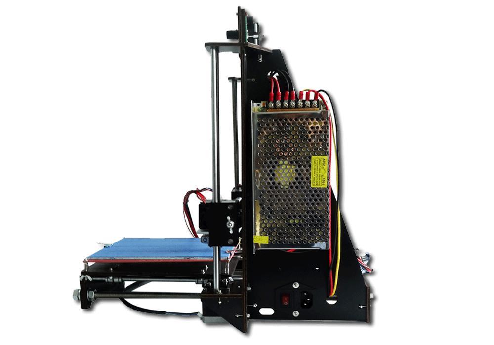
5 Fix the 25 power supply on the A2 board on the right sight of the frame with 3pcs 7 M3x8mm screws, then fix 20 3D power switch onto A2 board by using 6 M3 x16mm screws, 4 nuts and 3 M3 washers. The connection of 3D power switch and power supply cables are shown in the following figures. 2.4 Assembling of Motherboard Accessories: 30 Motherboard ; 7 M3x8mm screw x 4; 11 Motherboard Support Column x 4 As shown in the figures below, insert 4 pcs support columns into the A3 board on the left side of the framework with 4pcs 7 M3x8mm screws. The follow Figure 8.3, press 30 motherboard with its holes in alignment with the 4 columns. Pay 5

6 attention to the installation direction. The main Structure s Installation and Connections of Power cable ports The major effect of main structure is shown in Figure 9 and Figure 10. The cable ports of motherboard and their functions are shown in Figure 11. In order to get the right installation, it is suggested to see the finished product display pictures to get general idea of the overall fitting effects and to identify the installation directions and positions. 6
7 Figure 9 Figure 10 7
; 11. motor power of Right nozzle; 12. motor power of Z shaft; 13. motor power of Y shaft; 14. motor power of X shaft; 15.")
8 Figure 11 (1.power source of motherboard; 2. heating bed; 3. Left nozzle power (spare) ; 4.Right nozzle power; 5. Left nozzle driver(spare); 6. Right nozzle driver ;7.Z shaft driver; 8. Y shaft driver; 9.X shaft driver; 10.motor power of Left nozzle(spare); 11. motor power of Right nozzle; 12. motor power of Z shaft; 13. motor power of Y shaft; 14. motor power of X shaft; 15. Cooling fan of nozzle; 16.Cooling fan of Power source; 17. Z shaft stopper; 18. Y shaft stopper; 19. X shaft stopper; 20. LED port. 21.SD card ports;22.temperature sensor socket of Right nozzle; 23.temperature sensor socket of Left nozzle 24.temperature sensor of heating bed(spare); 25.function reset key of motherboard ) 1. Collect all assemblies before installation: A4, A5, Display screen, Q & P assembly as shown in the following Figures: 8


9 2. Find out 21 Dupont cable, use it to connect the motherboard on A2 and the power supply on A3. One end of the power cable connection is shown in Figure as below and the other end is connected to port 1 on the motherboard. 9


10 3. 3.Installation of P assembly - Printing bed Accessories: 6 M3 x 16mm screws x6 ; 4 nut x6 ; 22 Power cable x 5 (3 short +2 long) Align the holes of P assembly with the holes of previous installed main structure. Then fix the two and install P assembly to the main structure as shown in figure 18. Then follow figure 19 to install the bottom of P assembly to the A1 assembly. 4. Installation of 31 A4 assembly Accessories: 6 M3 x 16mm screws x3 ; 4 nut x3 ; 3 M3 Washer x3 Align the holes of A4 assembly to the A1 frame, fix it to the left bottom of the A1 10
11 assembly. Then connect the motor to port 15 on motherboard with short 22 Power cables, and connect the limit stopper cable to port 16 on motherboard. 5. Installation of 32 A5 assembly Accessories: 6 M3 x 16mm screws x3 ; 4 nut x3 ; 3 M3 Washer x3 Align the holes of A5 assembly to the A1 frame and install A5 assembly to the right bottom of the A1 assembly. Then connect the motor to port 11 on motherboard with the long 22 Power cables. 6. Installation of display screen Accessories: 6 M3 x 16mm screws x2; 4 nut x2 ; 3 M3 Washer x2 ; 13 display screen cable Align the holes of the display screen and A1 assembly to fix the two together. The LED display screen is outward as shown in Figure below. Connect the display screen to port 19 on the motherboard with 13 display screen cable. Port 19 on motherboard connect to EXP1 port on display screen, port 20 on motherboard connect to EXP2 port on display screen. 11

12 7. Installation of Q assembly Note: Because each size of assembly may bear some deviation on production, in order to obtain good installation and functions, it is suggested to pay attention to the installation of the Q assembly. If necessary, please adjust the right side of Q assembly to left or to right to ensure the normal functions, and adjust the length of the belt according to actual gap. Before assembly, the first Z-axis screw M5 ends connect flexible coupling 30, is prohibited after blowing hot and then install the flexible coupling to the M5 terminal end of the flexible coupling insert M5 depth of about 10mm. As shown below: 12


13 (1) Accessories: 38 Z top mount x 2; 6 M3 x 16mm screws x4; 4 nut x4 ; 3 M3 Washer x4 Align holes of the Z top mount with A1\A2 assemblies and with A1\A3 assemblies, fix them with screws as Figure shown below: (2) Accessories: 1 Smooth rod x2; 8 Screw locking ring x2 Get the guide rods 1 go through the hole of 38 Z top mount, 8 Screw locking ring and the outside bearing of the P assembly from up to down in both sides. 13
 Accessories: 2 Threaded rod x2 Get the 2 Threaded rod go through the hole of 38 Z top mount from up to down in both sides, rotating into the internal hole of P assembly, and insert to the shaft")
14 Adjust the distance between left and right side of P assembly, move 8 Screw locking ring to the joint of guide rod 1 and 38 Z top mount and fix it. (3) Accessories: 2 Threaded rod x2 Get the 2 Threaded rod go through the hole of 38 Z top mount from up to down in both sides, rotating into the internal hole of P assembly, and insert to the shaft couplings above the motors of A4 assembly and A5 assembly. Adjust the distance between the two sides of P assembly to ensure the correct installation. Adjust the horizontal distance between the outer ends of the two 2 Threaded rods as 320mm. Secure the tightening screws of shaft coupling on the upside of the motors. 14

15 (4) Connect the Stopper cable (red) of Q assembly to port 18 on motherboard. 8. Installation of Nozzle Accessories: 6 M3 x 16mm screws x2; 4 nut x2 ; 3 M3 Washer x2 First unscrew the cooling fan on the nozzle, dismantle the nozzle to L1,L2, L3 as three parts. Install L1 part to the movable part of P assembly with 6 M3 x 16mm screws, 4 nut and 3 M3 Washer. Please note that get 6 screw go through L1 first and then through the movable part of P assembly. Then install the nozzle and fan in the reverse steps as it was dismantled. Connect motor of the nozzle to port 10 on the motherboard with long power cable 22, and connect the fan cable to port 14 on motherboard. Connect power cable of nozzle to port 3 on motherboard. Connect temperature sensor of nozzle to port 21 on motherboard. 15

16 Debugging and Notes 1. Make sure the temperature sensor cable of the nozzle is in the correct position, as shown in Figure as below: 16

17 2. Make sure the connection of cables are in normal state. Then debug if position function of the limit stopper is normal, in particular pay attention to the debugging of Z-axis limit stopper. Click Function Key to choose Prepare, then choose Auto home and click confirm to check each stopper. Adjust the nut of the long screw on the left of Q assembly, adjust the lowest position of Z-axis moves down to ensure the gap between the nozzle and the printing bed. 3. Cut off the power and put the square glass with masking tape on top of the red heating bed, fix it with the 4 Dovetail clamps, please note the position of the dovetail clamps should not affect the functions of the nozzle and among others. Move the nozzle to check if the printing bed is parallel with the nozzle, and keep a proper gap. Then power on, check the original position of the nozzle and the gap between nozzle and the printing bed, make sure there is proper gap. 17
18 4.Check if the threaded rod of the Z-axis is deformed, make sure the gap between axis couplings of motors of A4 & A5 assemblies and the bed is 3mm.Try to keep the shaft line of Z-axis threaded rod and the output shaft of motor in the same straight line. Keep the horizontal distance of the upper and bottom sides of Z-axis threaded rod is equal. Adjust these distance and gaps until no noise occur when motor is moving on working. 5. The bundling of cables should not affect the moving space and functions of each parts. Adjust the heating temperature of the printing head according to practical conditions. 6.The sounds of rotational motors and cooling fans are normal. 7.Heating tube damage(suitable for all FDM 3D printers): When stop using the printer or need to clean the nozzle, use spanner to clamp the square aluminum block and unscrewing the nozzle. Make sure the square aluminum block can not move when unscrewing the nozzle, otherwise the heating tube would be damage. 8. Adjustment of belt: Cut the black nylon tie, readjust the size of the belt, fix it, then secure it with nylon tie. 9. Filament feeding port is the outside one, refer to Figure as below: 18


19 10. Spool holder with filament installation 19


20 20


21 11. Y-axis motor fixing (back-up accessory) Finish Product Display : 21

22 22

23 23
24 Product Parameters 1. Propose Environment Operation Environment: Good ventilation. No dust Temperature: 15 C~35 C Relative humidity: 20%~80%(no condensation) Storage Environment: Temperature:0 C~40 C Relative humidity: 10%~80% (no condensation. Free of corrosive gas and clean) 2. Printer Parameters Structure size: 200mmx200mmx180mm(these are the maximum size. It is advised to decrease practical size) Input voltage: 110V -220V Applicable operation system: Windows 7/8(32bit/64bit) Software: Cura Printing raw material: PLA Raw material property: Special PLA designed for 3D printing (exclusive composition) Layer precision: 0.1mm~0.5mm Positioning precision: X/Y axis, 0.011mm; Z-axis,0.025mm Filament diameter: 1.75mm Nozzle diameter:0.4mm 24
25 Moving axis speed: 30mm/s~100mm/s Recommended nozzle moving speed: 35~40mm/s Input file type: stl Cooling method: wind cooling Maximum temperature of nozzle: 260 C (usually 210 C) Maintenance 1. Cleaning nozzle The printing head have to be cleaned after the printer is used for a period of time. Dismantle the printing head, remove the fan and the step motor, as well as the black block at the feeding port on the motor, you will see the extruding gear of the nozzle, clean the material in the extruding gear will be ok, then install these parts back to the printer. 2. Tightening belt. Notes: (1). Belt should be seamlessly contacted with the belt wheel. (2). Forces of the two sides of the Y-axis wheel belt should be the same (3). X-axis shall be perpendicular to Y-axis 3. Maintenance of axis and threaded rods Oil the bearing steel of X,Y,Z axis with high quality lubricant. The oil amount is not supposed to be too much. Just a little to lubricate the surface will be good. 4. Trouble shooting 4.1 Offset: If offset remains after screw tightening, please check if the belt wheel is 25
26 on the same parallel line. 4.2 Abnormal temperature display Check if the thermocouple is correctly connected. If so, change the thermocouple. 4.3 Temperature display is N/A. Check if the thermocouple is correctly connected. If so, change the thermocouple X-axis moves abnormally with vibration. The X-axis motor cable should be changed. 4.5 LCD screen turns blue without information or sudden rebooting after printer is started or the Stopper switch of motor does not stop. Check if the sensor is connected correctly. If so, then change the sensor cable. 4.6 Cooling fan does not work. First check if the fan can rotate when temperature is over 40 C. If not, use screwdriver to check the ports connection or test it by battery. If still not work, replace a new fan. 4.7 Motor does not rotate, change the motor driver board. 1.Shifted layers Common Problems and Solutions (A).Screws are firmed but still shift a.check the pulleys make sure they are parallel b.check if belts are loose, tighten them B).Check drive on the mother board. Exchange drive boards of X Y Z for testing C).Check elements such as bearing on the Q module,make sure they are firm 2. Screen shown as below means temperature sensor or temperature wire is not 26
.")
27 connected well 27 is temperature of nozzle, 0 is setting temperature for nozzle 0 is temperature of platform, 0 is setting temperature of platform Check if connection of the wires of platform or mother board is connected well. If both temperature 0 are not changed, it means temperature is not setting yet or mother board broken. 3.X-axis moves abnormally or shaking (a). Check the bearing of the belts and see if they are damage or deformation (b). Check wires of the X-axis motor, if any problem change the wires 4. a.the LCD screen on but without display b.the machine restart suddenly after switch on c.the motor can not stop after touch the limit switch Check connection of the sensor s wires, if connection is no problem, there will be problem of the wires, change the wires. 5.The fan is not working. Make sure the temperature is above 50 C, if fan is not rotated,check the interface and reconnect it. Or test by battery, if still not rotated, change the fan. The default rotating speed of the fan is 255, if is 0,please adjust it to Motors can not rotate, check connection wires of the motors, exchange the 27
28 wires for testing, if motor rotating, change the wire, if not,change drive board of the motor. 7.Filament is blocked: a).filament is too thick b).dismantle the nozzle. 8.Sliding: filament is too thin,cut part of filament 9. Nozzle is blocked: heating tube is blocked by filaments, dismantle heating part and heat it to 220, then get filaments out with tweezers. 10. Abnormal temperature: thermocouple is damaged,change the thermocouple 11.Printing offset: Screw is loosened, check and tighten screw 12. Sample edge deformations: bed is too high, adjust the bed height 13. Filament is glued onto nozzle: supporting material are pulled by nozzle,reset the parameters 14. Filament does not flow out: model is faulted,transform the model into code and set parameters after model being corrected. 15.Driver or software cannot be installed: wrong system configuration, re-install the system 16. print samples cannot be glued on platform: too large gap between nozzle and bed,readjust the bed 17.Click any mode when printer is powered, the motor does not move,change a new printer identifier. 18.Tape cannot be moved off: heat the platform to 20 or 30 and take off the 28
29 tape completely. 19.When finish printing or need to change filament during printing. Please choose the function of discharge, do not pull out the filament by force,the way will deform the filament which is hot in the heating tube,thus will jam or damage the extrusion gear. 20.The wood fix Y-axis is easy fracture, if it is broken, request for A13 wood for replacement. 21.Z-axis can not move up and down or move very slowly, please operate Z-axis in controlling setting. Otherwise exchange the motor wires or drive board of the motors for testing. 22.Platform glass damaged. Do not press the platform glass heavily. After finish printing, use the blade to prize up the model carefully and take it down. Do not pull it up directly, this way will damage the platform glass easily. For the model which wasn t taken down on time. As after finish printing, the printer will be cooling down, temperature of the platform will turn down to normal, thus the model will be stick on the platform and hardly to take down, in this situation, heating the platform up to 100 C, then it can be taken down easily. 23.LCD screen is not on. (a). Check and confirm if connection wires of the screen and mother board are connected correctly. (b). Check if the white switch on the blue controller on the back of the screen is loose, firm it with screw and see if the screen is on. 29
30 24.The threaded rod bend, replace it. 25.Printer can not connect to computer: The computer without COM interface drive will not be able to be connected. 26.Filament break off or stop extrusion: Check if plastic extrusion gear is loose or damage, or the nozzles and heating tube are jam, or filament tray is stuck. 1. Quality guarantee Warranty statement and permit agreement Each product you bought is attached with the promise given by CTC. We ensure that each product manufactured by us is of high quality through strict accessory fabrication standards and assembling inspection flows. 2. After-sale guarantee (1) We promise to change or repair the product with quality problem within 3 days after your receipt of the product (free of charge and we will bear the two-way transport fees) (2) We promise to change or repair the product with quality problem within 7 days after your receipt of the product(free of charge and we will bear half of the two way transport fees) (3) We promise to change or repair the product with quality problem within 15 days after you receipt of the product free of charge. And you should bear the two-way transport fees. 30
 Do not upgrade the firmware(as Figure shown below).")
31 (4) We offer free of charge consultation service to you about any product problem after 15days since you have received the product. However, you should bear all the cost for any accessory change and the two-way transport fees. (5) Do not upgrade the firmware(as Figure shown below). Any damage caused by upgrading the firmware is not within the warranty policy. 3. Notice for return or change (1) Customer should carefully check if all the parts are included in the package according to bill of materials as soon as you receive the printer (2) CTC will not liable to any part damage caused if you have not complied with the installation instructions. And you should bear all the cost of any part needed to be changed and the transport fee. (3) Because DIY printer will be installed by customer, the printing quality varies from one customer to another. We will not accept any return request once the printer is completely installed. (3.1) Basic conditions for return/change: All the accessories, instruction manual and outer package of the product should be the same as it was sold to you. We will not accept return or change request if any one of the aforesaid is missed. You can keep the free-of-charge articles for product change; You should send the 31
32 free-of-charge articles to use with the product for product return. (3.2)Return /change due to quality problem. Please carefully check the completeness of product as soon as you have received the product. If any quality problem is found, please take a photo and contact us within 5 days. (3.3) Please note the following terms, otherwise, we will not offer return/change service to you. (1) Any product that you request to change/return shall have all the complete outer package, accessories and instruction manual, etc. (2)We will not accept return/change if the product has been stained or damaged by personal acts. (3) free-of-charge articles are not eligible for return/change. (4)No return/change is accepted if you have used non-ctc consumables. (5)Product that has been invoiced are not to be returned. You can change the product with quality problem. 4. About Product Care:(1) After you finish printing, try to clean all the residual consumables inside the nozzle to prevent nozzle being blocked next time. This is also the rudimentary maintenance for 3D printer. Note: We will not offer repair warranty if nozzle is blocked by consumables provided by other suppliers. (2) You can add some anti-lubricant to guide track once a month. (3) During printing, do not cut off the power directly or touch the conductive parts of printer with metal. 32
Contents Introduction Safety Issues Materials and Parts Notes... 3 Installation of Motherboard A1 Assembly A2 A
 ZHUHAI CTC ELECTRONIC CO., LTD CTC DIY Printer Installation and Use Manual A mature brand that has been tested by 10-years time focus on high-end science and technology, focus on 3D printing Thank you
Assembly Instructions of Geeetech Aluminum Prusa I3
 Assembly Instructions of Geeetech Aluminum Prusa I3 CONTENT Safety Instructions... 3 Preparation... 4 1. Unfold the box and check the package... 1 2. Assemble Y axis... 1 3. Build the printing platform...
JGAURORA 3D PRINTER MODEL: A5 USER GUIDE
 JGAURORA 3D PRINTER MODEL: A5 USER GUIDE Contents ----3D Printer User Guide 1. Preface... 2 1.1 Introduction...2 1.2 Safety advice... 2 1.3 Filament requirements...2 1.4 Environmental requirements...2
Building Instruction of Geeetech Prusa I3 pro W. 3D Printer
 Building Instruction of Geeetech Prusa I3 pro W 3D Printer Version 05-31-2017 Contents Safety Instructions... 2 Preparations... 3 1.Unfold the box and check the package... 4 2 Assemble the rods of a Y
Building Instructions of Geeetech Prusa I3 M201
 Building Instructions of Geeetech Prusa I3 M201 (Version 04-11-2016) CONTENT Safety Instructions... 1 Preparation... 2 1. Assemble the threaded rods of Y axis... 3 2. Assemble the front and back support
Assemble Manual of Geeetech Acrylic Prusa I3 (8mm)
") Assemble Manual of Geeetech Acrylic Prusa I3 (8mm) Warning: Shenzhen GETECH CO.,LTD. This kit contains tiny parts; please keep them away from kids under 3.. Building and operating 3D printer involves electricity,
Assemble Manual of Geeetech Acrylic Prusa I3 (8mm) Warning: Shenzhen GETECH CO.,LTD. This kit contains tiny parts; please keep them away from kids under 3.. Building and operating 3D printer involves electricity,
Building Instructions of Geeetech Prusa I3 M201
 Building Instructions of Geeetech Prusa I3 M201 (Version 11-25-2016) CONTENT Safety Instructions... 1 Preparation... 2 1. Assemble the threaded rods of Y axis... 3 2. Assemble the front and back support
WANHAO Duplicator i3. User Manual V1.2. Wanhao USA
 WANHAO Duplicator i3 User Manual V1.2 Wanhao USA 2015 www.wanhaousa.com Safety WARNING: The components on the Duplicator i3 generate high temperatures and move extremely fast. Reaching inside of the Duplicator
Installation and service instructions, warranty terms & conditions. DeeGreen. User Guide. Version 2.6
 Installation and service instructions, warranty terms & conditions DeeGreen User Guide Version 2.6 - 2 - Contents 1. Contents...- 3-2. Technical parameters...- 4-3. Safety instructions...- 4-4. Package
Prusa i3 Printer Assembly Guide
 Prusa i3 Printer Assembly Guide Special thanks to Carlos Sanchez and Miguel Sanchez for the graphics. All graphics captured from their great animation: http://www.carlos-sanchez.com/ Prusa3/ For copyright
Please read the safety instructions carefully before get started.
 Safety Instructions Please read the safety instructions carefully before get started. ANYCUBIC 3D printer generates high temperature. Do not reach inside of the printer during operation. Allow time for
To be the Chief Evangelist CR-10S Pro Printer Guide Book To make Top-quality 3D printer
 To be the Chief Evangelist CR-0S Pro Printer Guide Book To make Top-quality 3D printer This guide book is for standard CR-0S Pro. Please plug the power cord into a three-hole power jack. Detailed instructions
3D PRINTER USER MANUAL
 3D PRINTER USER MANUAL Table of contents page: 1. Introduction 2. Table of contents 3. Basic informations 4. General information 5. Glossary 6. Starter pack s content 7. Technical parameters 8. Device
5. E-axis assembly. 5. E-axis assembly. Written By: Jakub Dolezal manual.prusa3d.com/ Page 1 of 40
 5. E-axis assembly Written By: Jakub Dolezal 2018 manual.prusa3d.com/ Page 1 of 40 Step 1 Tools necessary for this chapter Needle-nose pliers for zip tie trimming. 2.5mm Allen key for M3 screws 2mm Allen
6. Pre-print checks. 3D Touch
 Page 1 1. 6. Pre-print checks........................................................................................... 1.1 a. Clearing the print bed..................................................................................
Quick Starter Manual for PrusaM201
 Quick Starter Manual for PrusaM201 Copyright Declaration The copyright of this specification belongs to the Shenzhen GETECH CO., LTD. (hereinafter referred to as the "Geeetech"), and all rights reserved.
Assembly Instructions of Geeetech Prusa I3 A pro
 Assembly Instructions of Geeetech Prusa I3 A pro (Version 04-11-2016) CONTENT Safety Instructions... 3 Preparation... 4 1. Unfold the box and check the package... 1 2. Assemble Y axis... 1 3. Build the
TRIPODMAKER BLACK EDITION USER MANUAL
 TRIPODMAKER BLACK EDITION USER MANUAL TABLE OF CONTENT Specifications and box content 1. Specifications of the Tripodmaker...4 2. Box content...5 3. Terminology...6 4. Attentions and warnings...8 Unboxing
TL4076 Top 5 Tips Get to know your TL4076
 TL4076 Top 5 Tips Get to know your TL4076 Thermal Break with Teflon liner (behind fan) Hot End Assembly Fan Heat Block Extruder with toothed gear(brass) and idler (steel) Filament Guide Tube Nozzle Cable
Introduction to 3D Printing
 TAKE HOME LABS OKLAHOMA STATE UNIVERSITY Introduction to 3D Printing by Sean Hendrix 1 OBJECTIVE The objective of this experiment is to introduce you to 3D printing, by having you print some simple parts
Modix Big-60 Assembly Instructions Part 1
 Modix Big-60 Assembly Instructions Part 1 Version 1.0, October 2017 Menu 1. X Idler Pulley Assembly... 3 2. Connecting X Axis Brackets to Z Profiles... 4 3. Assemble X Rails on X Top Profiles... 6 4. Assemble
Witbox 2. Quick start guide
 Witbox 2 Quick start guide Welcome. Thank you for choosing us. This manual will help you to use your new 3D printer correctly. Welcome to the world of Witbox 2. How do I use this manual? To make sure that
Maintenance Manual. Hephestos
 Hephestos 2016 Mundo Reader SL. All rights reserved. The reproduction, copying, distribution, publication or modification of this material is strictly prohibited unless carried out with the express prior
5. Extruder Assembly
 5. Extruder Assembly Guide for the assembly of the Extruder. Written By: Josef Prusa 2018 manual.prusa3d.com/ Page 1 of 24 Step 1 Get the necessary tools 2.5 and 1.5 mm Allen key Needle-nose pliers 2018
Pressure Sealer ES-5000 ES User Manual. <Rev >
 ES-5000 User Manual 1 1. Introduction Table of Contents 2. Installation 3. Features 1) Specifications 2) General views 4. How to Operate 1) Form Preparation 2) Loading forms 3) Start 4)
Important notice Upper supports for Z axis Pulley Corner for Y axis Right X axis and left X axis Chain coupling for left X axis
 Warranty and FAQ G004260 Important notice You can personalise your Prusa i3 HEPHESTOS and update it with the latest innovations that appear in the community. However, it is important that you understand
Desktop 3D Printer. User Manual
 Desktop 3D Printer User Manual TM Contents WELCOME 1 Safty 2 Specifications 3 How it Works 4 SETUP 5 Unpacking 6 Accessory 9 Tool Box 10 Setting Up Mankati Fullscale XT Plus 11 Fullscale XT Plus Outlook
SLIDING DOOR OPERATOR INSTRUCTION MANUAL
 SLIDING DOOR OPERATOR INSTRUCTION MANUAL (MODEL NO. 1071.101 & 1071.102) Please carefully keep this manual for good maintenance. Caution Be sure the door opener is far away from moisture, vibration, and
NWA3D A5 User Manual
 1. NWA3D A5 3D Printer Part Diagrams 2. Assembling the Spool Holder 3. Leveling the Build Plate 4. Loading and Unloading Filament 5. Operation: The Four Steps in 3D Printing 6. Troubleshooting 7. Additional
Upgrade v3 to v3.2. SeeMeCNC Guides. Upgrade v3 to v3.2. Rostock Max v3 Uprgade to v3.2. Written By: SeeMeCNC seemecnc.dozuki.
 SeeMeCNC Guides Upgrade v3 to v3.2 Rostock Max v3 Uprgade to v3.2 Written By: SeeMeCNC 2018 seemecnc.dozuki.com/ Page 1 of 34 INTRODUCTION This guide is intended to Upgrade a Rostock Max v3 to a Rostock
GETINGE ProSeal Classic/Plus/ Premium SERVICE MANUAL
 GETINGE ProSeal Classic/Plus/ Premium SERVICE MANUAL EN P/N: V.9 Service manual Getinge ProSeal V.9 V.9 History Name Version Date Comment Coen van de Laar.8 26-02-204 Manual adjusted after first review
Modix Big-60 Assembly Manual Part 2
 Modix Big-60 Assembly Manual Part 2 Version 1.0, October 2017 Menu 1. Motors & End Stop Wiring... 3 2. Controller Wiring Check... 6 3. Extruder Wiring... 7 4. Electronic Box Cover... 9 5. Filament Sensor...
DLS-TP400 USER S MANUAL
 DLS-TP400 USER S MANUAL TPMS CONTENTS Safety Precautions...... 2 Packing List... 3 Standard Tools and Accessories... 4 Display Desktop Base Installation... 5 Cigarette Lighter Bracket Installation... 6
infinite possibilities Industrial 3D Printing, Affordable Prices SHANGHAI INTAMSYS TECHNOLOGY CO. LTD.
 infinite possibilities Industrial 3D Printing, Affordable Prices FUNMAT Industrial Quality Desktop 3D Printer Insulated Chamber Able to print standard filaments without warping and cracking issues Filament
8. Electronics assembly (B3/R2 design)
") 8. Electronics assembly (B3/R2 design) Written By: Jakub Dolezal 2018 manual.prusa3d.com/ Page 1 of 31 Step 1 Tools necessary for this chapter Needle-nose pliers for zip tie trimming. 2.5mm Allen key for
8. Electronics assembly (B3/R2 design) Written By: Jakub Dolezal 2018 manual.prusa3d.com/ Page 1 of 31 Step 1 Tools necessary for this chapter Needle-nose pliers for zip tie trimming. 2.5mm Allen key for
CUSTOM CAN Custom Can Pneumatic Filling Machine Instructions for Operation and Maintenance
 CUSTOM CAN Custom Can Pneumatic Filling Machine Instructions for Operation and Maintenance U-POL US, Inc., 630 Selvaggio Dr, Suite 300, Nazareth, PA 18064 Tel: (800) 340 7824; Fax: (800) 787 5150 Email:
Unpacking Instructions
 Unpacking Instructions by Revolution 3D Printers Infinity3D_Unpacking_Instructions_V1.1 1 Copyright 2016, Revolution 3D Printers Copyright 2016 Revolution 3D Printers, Victoria, BC File version Infinity3D_V1.0,
V1.0. Showven Technologies Co.,Ltd.
 V1.0 Showven Technologies Co.,Ltd. SONICBOOM TM SMOKEJET USER MANUAL Foreword Thanks for choosing SHOWVEN SONICBOOM TM SMOKEJET. Please read following manual carefully and completely before operating this
Wind/Solar Hybrid Controller (Boost/Buck) User Manual
 User Manual") Wind/Solar Hybrid Controller (Boost/Buck) User Manual CONTENTS 1 Safety Instructions... 1 2 Product Introduction... 2 2.1 General Description... 2 2.2 Functions & Features... 2 2.3 Design & Dimensions...
Wind/Solar Hybrid Controller (Boost/Buck) User Manual CONTENTS 1 Safety Instructions... 1 2 Product Introduction... 2 2.1 General Description... 2 2.2 Functions & Features... 2 2.3 Design & Dimensions...
MacBook Pro 13" Unibody Mid 2009 LCD Replacement
 MacBook Pro 13" Unibody Mid 2009 LCD Replacement Written By: Walter Galan ifixit CC BY-NC-SA www.ifixit.com Page 1 of 25 INTRODUCTION Save money by replacing just the LCD rather than the whole display
TeeBox. The Suitcase 3D printer. BY:
 TeeBox The Suitcase 3D printer. BY: Eindhoven The Netherlands Contents Liability... 2 Returns... 2 WARNING... Error! Bookmark not defined. TRICKS AND TIP... 4 PART 1 ---Y AXIS (PRINT BED)... 7 Fasten heatbed
Strip Width Gauge Operating and Service Instructions
 Strip Width Gauge VABM 4-00 Operating and Service Instructions erstellt am 25.2.2002 freigegeben am Bemerkungen Rev.01 Seiten: Name: Rietdorf Name: Name: measuring - controlling - recording - automation
MP Maker Pro Mk.1 P/N User's Manual
 MP Maker Pro Mk.1 P/N 33013 User's Manual CONTENTS SAFETY WARNINGS AND GUIDELINES... 3 INTRODUCTION... 5 FEATURES... 5 CUSTOMER SERVICE... 5 PACKAGE CONTENTS... 6 PRODUCT OVERVIEW... 7 Front View... 7
Documentation version 1.42 ASSEMBLY INSTRUCTIONS REV 1.1
 Documentation version 1.42 ASSEMBLY INSTRUCTIONS REV 1.1 / 2 INTRODUCTION / 3 INTRODUCTION Target : Prupose a visual guide of the differents steps to build and use a µdelta printer Designers : Hugo Flye
FD 120 Card Cutter MAINTENANCE MANUAL. MyBinding.com 5500 NE Moore Court Hillsboro, OR Toll Free: Local: /2011
 FD 120 Card Cutter 5/2011 MAINTENANCE MANUAL SAFETY PRECAUTIONS Always observe the cautions and warnings given below to prevent personal injury or property damage. The degree of danger and damage that
BWS-80 Wire Stripping Machine
 BWS-80 Wire Stripping Machine Operation Manual BLUEDOG WIRE STRIPPERS www.copper-wire-stripper.com Contents 1. Specification and composition 1-4 2. Operation 4-5 3. Common trouble shooting and maintenance
Dust cover. Plug. Outlet. Wire pole holder
 Thank you for choosingxtreme machine,baby -Mammoth (4 head), designing with double gear-driving, planetary grinding with four plates. The machine speed can reach 1800 rpm. Aluminum alloy gear box with
PRSalpha Air Drill (Double Valve)
") 888-680-4466 ShopBotTools.com PRSalpha Air Drill (Double Valve) Copyright 2016 ShopBot Tools, Inc. page 1 Copyright 2016 ShopBot Tools, Inc. page 2 Table of Contents Overview...5 Spindle Mounting Plate...6
888-680-4466 ShopBotTools.com PRSalpha Air Drill (Double Valve) Copyright 2016 ShopBot Tools, Inc. page 1 Copyright 2016 ShopBot Tools, Inc. page 2 Table of Contents Overview...5 Spindle Mounting Plate...6
Hand Pallet Truck NC. Operation Manual
 Hand Pallet Truck -------NC Operation Manual Operation Manual 1 Application Range This product is suitable for using in rated load of up to 5500lbs. This PL5500HD is the perfect jack for handling palletized
Geeetech Prusa I3 M201
 Geeetech Prusa I3 M20 Copyright Declaration The copyright of this manual belongs to the Shenzhen GETECH CO., LTD. (hereinafter referred to as the "Geeetech"), and all rights reserved. No part of this specification
Heated Bed Installation Instructions
 Heated Bed Installation Instructions Overview The glass panel is heated by way of a heater element which is bonded to the glass panel and controlled by a digital temperature controller. The temperature
Assembly & Installation Guide Makerbot Rep2X and clones
 Assembly & Installation Guide Makerbot Rep2X and clones The Bondtech extruder upgrade kit for Makerbot and clones uses high-quality industrial pneumatic push-fit fittings for attaching the bowden tube.
Trifecta 800 3D Printer. User s Guide
 Trifecta 800 3D Printer User s Guide Table of Contents 3 SAFETY WARNINGS 4 WARRANTY 5 SPECIFICATIONS 6 PRINTER OVERVIEW 7 UNBOXING 9 10 11 12 13 14 15 17 18 20 22 25 26 FILAMENT INSTALLATION PRINT BED
Geeetech Prusa I3 M201. Assembly Manual
 Geeetech Prusa I3 M20 Assembly Manual SUPPORT Thanks for choosing Geeetech, we strive to provide a satisfied and pleasant shopping experience for you, but we do understand there may be some questions you
NWA3D A31 User Manual
 1. 3D Printer Parts Diagram 2. Assembly 3. Fine-Tuning 4. Leveling the Build Plate 5. Loading and Unloading Filament 6. Operation: The Four Steps in 3D Printing 7. Troubleshooting Version 2.0 8. Additional
TPMS TP200 USER S MANUAL
 TPMS TP200 USER S MANUAL V6.03.21 CONTENTS Packing List... 2 Standard Tools and Accessories... 3 Display Power On... 4 Installation of tire sensors... 5 Driving checking... 6 USB charging Socket... 6 Display
SERIES A & AA ROLLER DOORS INSTALLATION GUIDE
 SERIES A & AA ROLLER DOORS INSTALLATION GUIDE THESE INSTRUCTIONS ARE PROVIDED FOR USE BY EXPERIENCED INSTALLERS OF GARAGE DOORS BY UNDER-TAKING THE INSTALLATION OF THIS DOOR, THE INSTALLER UNDERSTANDS
Customer Name: Serial Number: Y-Axis Stall
 Technician Name: Date: Technician Name: Date: Customer Name: Serial Number: Y-Axis Stall Issue Explanation and Background Each drive motor on the machine (the x, y and z axes motors) has a sensor called
Trouble Shooting Guide for Hubbell Systems
 Trouble Shooting Guide for Hubbell Systems NOTE: Hubbell Special Products discontinued operations in 2008, so there is a very limited number of repair parts available for motor repair. In some ways, this
Energy-saving Servo Motor
 Energy-saving Servo Motor User Guide Perface GAUTION: PLEASE READ INSTEUCTION MANUAL CAREFULLY BEFORE OPERATEING. THE INSTALLATION AND OPERATION MUST BE OPERATE UNDER PROFESSIONAL TRAINED STAFF. This product
Instruction Manual For Auto Shift Hydraulic Lift Table
 Instruction Manual For Auto Shift Hydraulic Lift Table Model Number: CART-550-AS Note: Owner/Operator must read and understand this Instruction Manual before operating the lift & tilt table. Contents 1
SERVICE MANUAL. Chairman. Playman/Robo
 SERVICE MANUAL Chairman Playman/Robo US How to contact Permobil Permobil Inc. USA 6961 Eastgate Blvd. Lebanon, TN 37090 USA Phone: 800-736-0925 Fax: 800-231-3256 Email: info@permobilusa.com Head Office
BMS24. Thanks for your purchasing the BMS24 for your vehicle.
 BMS24 for 2S-24S LiPo & LiFe Low power consumption High accuracy 2.8 TFT LCD display Programmable Thanks for your purchasing the BMS24 for your vehicle. Read the ENTIRE instruction manual to become familiar
BMS SV 24S for 2S-24S LiPo, LiFe & LiTO&others Low power consumption High accuracy 2.8 TFT LCD display Programmable
 BMS SV 24S for 2S-24S LiPo, LiFe & LiTO&others Low power consumption High accuracy 2.8 TFT LCD display Programmable Thanks for your purchasing the for your vehicle. Read the ENTIRE instruction manual to
SeeMeCNC Guides. Orion Delta HE280 Hotend Upgrade. This How-to Guide will walk you through the steps of upgrading to the HE280 Hotend
 SeeMeCNC Guides Orion Delta HE280 Hotend Upgrade This How-to Guide will walk you through the steps of upgrading to the HE280 Hotend Written By: JJ Johnson 2017 seemecnc.dozuki.com Page 1 of 18 INTRODUCTION
OPERATION INSTRUCTIONS GFA-W-150\300\500\1000
 OPERATION INSTRUCTIONS HORIZONTAL SELF-SUCTION FILLER SERIES GFA-W-10\300\00\1000 Please operate in accordance with the instructions strictly. CONTENTS Overview Maintenance and Service Application Replacement
SERVICE MANUAL ULTIMATE 200
 SERVICE MANUAL ULTIMATE 200 This manual is for: 20 200-120 Ultimate 200 std. 120V 60 Hz 20 200-240 Ultimate 200 std. 240V 50 Hz 20 201-120 Ultimate 200 DMX 120V 60 Hz 20 201-240 Ultimate 200 DMX 240V 50
Documentation version ASSEMBLY INSTRUCTIONS
 Documentation version 1.6.30 ASSEMBLY INSTRUCTIONS / 2 INTRODUCTION / 3 INTRODUCTION Target : Propose a visual assembly instruction guide of the MicroDelta Rework. Designers of the MicroDelta Rework :
Ultimaker 2 Extended THINK LARGE, PRINT BIG USER MANUAL V2.1
 Ultimaker 2 Extended THINK LARGE, PRINT BIG USER MANUAL V2.1 2 TABLE OF CONTENTS 1. ULTIMAKER 2 EXTENDED 4 Ultimaker 2 Extended at a glance 5 Specifications 7 2. GETTING STARTED 8 Unboxing 9 Installation
(Designed & Manufactured by RC EXPLORER TEAM) Radon V2 series Brushless Speed Control System User Guidelines
 Radon V2 series Brushless Speed Control System User Guidelines") (Designed & Manufactured by RC EXPLORER TEAM) Radon V2 series Brushless Speed Control System User Guidelines 1. Technical /Specifications: Model: Radon Pro V2 Radon Pro V2 1S Radon Sport V2 Continuous
(Designed & Manufactured by RC EXPLORER TEAM) Radon V2 series Brushless Speed Control System User Guidelines 1. Technical /Specifications: Model: Radon Pro V2 Radon Pro V2 1S Radon Sport V2 Continuous
Preparing The Printer For Maintenance
 Chapter 4 Preparing The Printer For Maintenance Preparing The Printer For Maintenance WARNING IMPORTANT Unplug the printer power cord from the printer or power outlet before you do any maintenance procedure.
Written By: Josef Prusa
 7. PSU & Heatbed assembly PSU and Heatbed guide Written By: Josef Prusa 2017 manual.prusa3d.com/ Page 1 of 17 Step 1 Getting the necessary tools 2 and 2.5 mm allen key Needle-nose pliers Step 2 3D printed
PNL-MS Belt Conveyor with Metal Detector
 PNL-MS Belt Conveyor with Metal Detector Date: Apr, 2013 Version: Ver.B (English) Contents 1. General Description... 7 1.1 Coding Principle... 8 1.2 Features:... 8 1.2.1 Specifications Table... 10 1.2.2
Introduction. Preparation to Installation. Installation of SLAMSTOP
 INSTALLATION MANUAL Introduction Table of Contents About SLAMSTOP About this Manual SLAMSTOP is an innovative door closing system intended for smooth and noiseless automatic door closing of a car. The
BMS16. Thanks for your purchasing the BMS16 for your vehicle.
 BMS16 BMS for 2S-16S LiPo & LiFe Low power consumption High accuracy 2.8 TFT LCD display Programmable Thanks for your purchasing the BMS16 for your vehicle. Read the ENTIRE instruction manual to become
User s Manual Wind/Solar Hybrid Controller
 User s Manual Wind/Solar Hybrid Controller Please Read This User Manual Carefully Prior to Installation and Operation of This Product. 2012 V1.0 Notices 1) Battery reverse-connection is forbidden. 2) Battery
Assembly Manual FELIX One
 Assembly Manual FELIX One Version 1.0 2018 www.felixprinters.com support@felixprinters.com Zeemanlaan 15 3401 MV IJsselstein The Netherlands Introduction Table of Content Dear Customer, Thank you for choosing
User s Manual. Wind/Solar Hybrid Street Light Controller. Please Read This User Manual Carefully Prior to. Installation and Operation of This Product.
 User s Manual Wind/Solar Hybrid Street Light Controller Please Read This Carefully Prior to Installation and Operation of This Product. 2012 Version: 1.0 1. Product Introduction The wind/solar hybrid street
Cubicon Single (3DP-110F)
") Cubicon Single (3DP-110F) Operation Manual Please read the safety cautions carefully before using the product, and use the product appropriately. This document is provided to ensure the safety of users
Cubicon Single (3DP-110F) Operation Manual Please read the safety cautions carefully before using the product, and use the product appropriately. This document is provided to ensure the safety of users
Read Chapter 8 Servicing Machine in the Manual for general guidelines
 Page 1 of 6 Read Chapter 8 Servicing Machine in the Manual for general guidelines The PlasmaCAM will not work on a GFI circuit. Earth ground the grates of the PlasmaCAM. Computer Configuration A. PlasmaCAM
Wheel Angle Sensor Kit Installation
 Wheel Angle Sensor Kit Installation Item Component Part Number Qty 1. WAS Bracket Kit 200-0247-02 1 2. WAS Assembly Kit 200-0468-01 1 3. Instruction Guide 602-0401-01 1 602-0401-01-A Overview Always shut
UM3 Spare Parts Ultimaker 3 Spare-Parts Version /06/18
 Ultimaker 3 Spare-Parts Version 1.2 13/06/18 Housing 1156 Z-Shaft Cap Bottom 1901 Controler Electronics Cover 1902 Main Board Electronics Cover 1903 Cable Cover 1904 Wifi Cover 1905 Print Table Back Cover
Quick Start Guide. Caution. Warning. This guide only applies to Dreamer 3D printer of Flashforge
 Quick Start Guide Caution Warning. Do not peel the yellow film from the build plate. It is heat-resistant tape, which makes objects stick to the build plate easily.. Do not remove the wrapping around the
RM 12V/24V Series Solar Charge Controller User s Manual
 RM 12V/24V Series Solar Charge Controller User s Manual Notice Before operating the product, please read this User Manual carefully to understand its correct usage. After reading it, please keep it properly
advanced FLOW engineering Instruction Manual P/N: Make: RAM Model: Diesel Trucks Year: Engine: L6-6.7L (td)
") advanced FLOW engineering Instruction Manual P/N: 42-12035 Make: RAM Model: Diesel Trucks Year: 2013-2016 Engine: L6-6.7L (td) Please read the entire instruction manual before proceeding. Ensure all components
advanced FLOW engineering Instruction Manual P/N: 42-12035 Make: RAM Model: Diesel Trucks Year: 2013-2016 Engine: L6-6.7L (td) Please read the entire instruction manual before proceeding. Ensure all components
SWING GATE OPENERS 24V DC GEAR MOTOR
 SWING GATE OPENERS 24V DC GEAR MOTOR FOR RESIDENTIAL USER MANUAL Flashing Light Push Button Control box Gate 2 Gate 1 Index 1. Warnings 2 4. Technical Characteristics 16 2. Product Description 2.1 Applications
VBK 2596/12E/RSF. Thickness and Width Gauge for Strip and Profile. Operating- & Service Instructions. (with lateral guide rollers)
") Thickness and Width Gauge for Strip and Profile (with lateral guide rollers) VBK 2596/12E/RSF Operating- & Service Instructions erstellt am 5.2.1998 freigegeben am Bemerkungen Rev.01 Seiten:16 Name: Rietdorf
Thickness and Width Gauge for Strip and Profile (with lateral guide rollers) VBK 2596/12E/RSF Operating- & Service Instructions erstellt am 5.2.1998 freigegeben am Bemerkungen Rev.01 Seiten:16 Name: Rietdorf
OWNER S MANUAL Kellen Gross Dr., Yankton SD Phone: TRUXEDO ( ) Fax: (605) Web Site:
 Fax: (605) Web Site:") Owner s & Installation Manual READ INSTRUCTIONS - Failure to assemble cover properly will void warranty. OWNER S MANUAL Damaged or missing parts? Call 1-877-878-9336 Mon - Fri 8 am - 5 pm CT Parts will
Owner s & Installation Manual READ INSTRUCTIONS - Failure to assemble cover properly will void warranty. OWNER S MANUAL Damaged or missing parts? Call 1-877-878-9336 Mon - Fri 8 am - 5 pm CT Parts will
M2 Wiring. Table of Contents
 M2 Wiring Table of Contents M2 Wiring Harness... 2 RAMBo... 3 Wire Harness 1... 4 Wire Harness 2... 5 Wire Harness 3... 6 Wire Harness 4... 7 Wire Harness 5... 8 Connecting Wiring Harness to M2 Printer...
USER MANUAL BRUSHLESS SPEED CONTROLLER S5-RTR ESC S5A-RTR ESC RC CARS & TRUCKS
 USER MANUAL BRUSHLESS SPEED CONTROLLER S5-RTR ESC S5A-RTR ESC RC CARS & TRUCKS Declaration Thanks for purchasing our Electronic Speed Controller (ESC). High power system for RC model can be very dangerous,
3. Extruder Assembly
 3. Extruder Assembly Guide for the assembly of the Extruder. Written By: Josef Prusa 2017 manual.prusa3d.com Page 1 of 22 Step 1 Get the necessary tools 2.5 and 1.5 mm Allen key Needle-nose pliers Step
Bondtech for Prusa i3
 Bondtech for Prusa i3 Assembly and installation manual This work is licensed under a GNU General Public License v3.0 Table of Contents Acknowledgements 1 Introduction 1 Compatibility 2 What s in the box?
LS1024BP/ LS2024BP. Solar Charge Controller USER MANUAL
 EPSOLAR LS1024BP/ LS2024BP Solar Charge Controller USER MANUAL Thank you very much for selecting our product! This manual offers important information and suggestions with respect to installation, use
Jass.Performance Low Profiles Installation Manual
 Jass.Performance Low Profiles Installation Manual The Jass.Performance Low Profiles are featuring: Fully reversible upgrade of the stock headlight bodies. Premium branded E-signed, TÜV aprooved Hella Headlights
How to operate TBC-555L
 TBC-555L. How to operate TBC-555L TBC-555L 1. An example (Cutting length : 70mm, Cutting quantity : 120 pcs) Turn on the POWER SW. Set cutting length. (Press the following buttons in order.) Set cutting
SPECTRE DRONE USER MANUAL
 SPECTRE DRONE USER MANUAL PRODUCT CODE: ZXSPT www.zero-x.com.au www.zero-x.co.nz v2 Thanks for purchasing a Zero-X Spectre Drone, get ready to have the time of your life! We re sure your Zero-X Spectre
Customer Name. Instruction for Operation. Single Head Sleever
 Customer Name Instruction for Operation Single Head Sleever Content Reload of Sleeve Roll (page 3~5) Sleeve Feeding (Page 6~7) Sleeve Sensor Positioning (Page 8~10) Holder Installation (Page 11~13) Splice
Desktop 5.5 Z Axis Retrofit
 Page 1 Kit parts Desktop 5.5 Z Axis Retrofit Carriage plate with stop bolt and Z proximity switch installed Zip ties Spare bolts Spindle mounting plate with stop bolt, spring mount, and rail Z proximity
Operating & Installation Manual
 Operating & Installation Manual (ZH1.5kw wind turbine system) Company Name:YUEQING ZONHAN WINDPOWER CO.,LTD. Address:NO.195,Chengxi Road,Yuecheng,Yueqing,Zhejiang,P.R.China Zip Code:325600 Tel:86-577-62529820
INSTRUCTION MANUAL VERSION 1 ISSUED 23/11/17 MODEL NUMBER: HE161192
 INSTRUCTION MANUAL VERSION 1 ISSUED 23/11/17 MODEL NUMBER: HE161192 IMPORTANT Getting the most out of your 3D Printer Touch: Read the manual carefully It will help you set up with ease Visit wwwcocoonproductscomau