Assemble Manual of Geeetech Acrylic Prusa I3 (8mm)
|
|
|
- Octavia Marshall
- 6 years ago
- Views:
Transcription

1 Assemble Manual of Geeetech Acrylic Prusa I3 (8mm)

2 Warning: Shenzhen GETECH CO.,LTD. This kit contains tiny parts; please keep them away from kids under 3.. Building and operating 3D printer involves electricity, so all necessary precautions should be taken and adhered to. 3. Building a 3d printer requires a certain amount of handling ability and some common sense and working principle of 3D printer. However, do not worry; with this build instruction in hand, you can finish the assembly easily. Unfold and check the package Unfold the package and take all the parts out to check the condition of the items. As you can see, all the parts are packed very carefully.


3 All the acrylic plate has been etched with part ID.

4 Tips:. Before assembly, you are advised to put all the parts, especially the screws and nuts in order, which will save you a lot of time looking for the required parts.. The part ID is corresponding to the number labeled on the bag of every part.
5 Assemble Y axis (the bottom part of the chassis). Assemble the rods of a Y axis Step. Assemble the threaded rods. Required parts M0 threaded rod NO.5 Acrylic Fender NO.A 4 M8 spring washer 6 NO.8 M0 washer 8 NO.9 M0 nut 8 NO. Thread the nuts and washers into the two M0 threaded rods separately. The order should be: M0 washer > M8 spring washer >M0 screw > M0 screw > M0 washer > acrylic fender > M0 washer > M8 spring washer > M0 screw > M0 screw > M8 spring washer > M0 washer

6 Step. Assemble the smooth rods Required parts M8 smooth rod NO.3 LM8UU Linear bearings 4 NO.39 Slide bearings on each smooth rod. Before you slide the bearings please make sure they are clean.
7 .. Attach the front and rear Acrylic support plates of the rods. Required parts Acrylic plate( front) NO. A9, A 0 Acrylic plate( back) NO. A, A M0 washer 4 NO.9 M0 nut 4 NO. Slide the rods into the acrylic plate, Adjust the length so that the smooth rods fit snugly between the front and back piece. Each corner gets a washer and a nut. Adjust the inner and outer nuts so that the end of the rod is flush with the outside M0 nut. Do the same on all four corners.

8 * Tips: the Y-axis must be a rectangle, that is the rods on both side should be parallel, so is the front and back plate. Otherwise it will cause obstruction for the belt later.

9 . Assemble the Y idler Shenzhen GETECH CO.,LTD Required parts 64ZZ Ball bearing NO.38 Y belt holder NO.66 M3 x 0 screw NO.7 M3 wing nut NO.5 M4 x5 screw NO.35 M4 lock nut NO.4 Step. Thread the M3 x 0 screw through the Y idler piece. Put the M4 x5 screw through the holes with the 64ZZ bearings in between. Lock the other end with a M3 nut.

10 Step. Mount the assembled idler onto the front support plates. And screw it with a wing nut. *Please leave enough room for the belt between the ball bearing and the screw.

11 .3 Mount the Y motor Required parts Y-axis motor block NO. A3 Stepper motor NO.76 pulley NO.43 M3 x screw 3 NO.5 M3 x 6 screw NO.6 M3 square nut NO.6 Step. Mount the pulley on the motor shaft, one of the screws should be screwed on the cross section of the shaft. Do not screw too tight to turn smoothly.

12 Insert the motor block into the slot; you may need to use a little strength to do this. But be careful in case the Acrylic broke down. Then screw the motor on the block plate with M3 x 0 screws.

13 .4 Build the printing platform Shenzhen GETECH CO.,LTD Required parts Printing platform NO.A5 Acrylic fender 4 NO.A6 Y axis belt mount NO.67 Zip tie 4 NO.54 M3 x 0 screw NO.4 M3 x 0 screw 8 NO.7 M3 nut 8 NO. Step. Mount the belt mount on the bottom side of the platform with M3 x 0 screws.

14 Step. Mount the 4 Acrylic fenders on the platform with M3 x 0 screws and M3 nuts on the same side with the belt-mount. Step3. Get the build platform plate zip-tied to the 4 linear bearings of Y- Axis. *The belt-mount and the fenders are under the platform.


15 Step4. Mount the belt.
 Fix it on the belt -mount with a M3 x 0 screw and washer.")
16 Required parts Shenzhen GETECH CO.,LTD belt NO.4 M3 x 0 screw NO.4 M3 washer NO.7 Drill a hole on one end of the belt(the hole can be as the diameter of the M3 screw, leave enough margin ) Fix it on the belt -mount with a M3 x 0 screw and washer. Thread the belt through the pulley on the Y motor and the Y idler. Drill a hole on the other end of the belt and fix it on the belt -mount with a M3 x 0 screw and washer. Step5. Attach he heated bed.
17 You can also attach the heat bed later. Shenzhen GETECH CO.,LTD Required parts Heat bed NO.7 Borosilicate glass NO.7 Heating wire NO.5 Thermistor Attached on the bed Thermometry wire NO.50 Wing nut 4 NO.5 Spring 4 NO.37 M3 x35 screw 4 NO.9 clamp 4 NO.5 *The circled part needs soldering.


18 Mount the heat bed on the platform with 4 M3 x30 screws and wing nuts with springs in between. Clamp the heat bed and the glass sheet.

19 3 Assemble Y - Z axis The main frame is held upright after the acrylic fender washers on the Y axis threaded rods. The front of the plate should be sticking out a lot further than the back. Screw up the frame to the threaded rod of Y-axis. Required parts X-Z frame NO.A Acrylic fender NO.A M3 x 0 screw 4 NO.7 M3 nut 4 NO.

20 4 Mount the fan Required parts Fan NO.7 M3 x 30 screw 4 NO.8 M3 locknut 4 NO.3 Fix the fan on the right side of the frame with 4 M3 x 30 screw and locknut. Mind the direction of the wires.

21 5 Assemble the right and left side panel Required parts Acrylic left panel NO.A Acrylic right panel NO.A3 M3 x 6 screw 8 NO.6
 6. Assemble the Z-axis bottom mount Required parts Z Motor fixed plate NO.")
22 M3 square nut Shenzhen GETECH CO.,LTD 8 NO.6 Screw up the X-Z frame and the side panel then connect the rear part of the Y axis and the side panel together. You may need to adjust the distance of the X-Z frame to the rear plate. 6 Assemble the Z axis (the vertical axis) 6. Assemble the Z-axis bottom mount Required parts Z Motor fixed plate NO.A4, A5 Z Motor support plate 4 NO.A6, A7 M3 x 6 screw 8 NO.6 M3 square nut 8 NO.6


23 Screw up the acrylic plates with M3 x 0 screws and M3 square nuts. *The right and left bottom mount are different; the left one has a mount for the Z end stop. Please look at the following picture.
24 6. Assemble the Z motors Required parts Stepper Motor NO.76 M3 x screw 8 NO.5 Step.Thread the wires of the motors through the holes

25 Step. Screw up the motors with M3 x screws.

26
27 7 Assemble the X axis (the horizontal axis) 7. Assemble the X-Axis Idler Required parts 64ZZ Ball bearing NO.38 X belt holder NO. 66 M3 X30 screw NO.8 M4 X5 screw NO.35 M4 locknut NO.4 M3 wing nut NO.5 X-axis end LM8UU linear bearing NO.P NO.40 Put the screw through the printed Y idler piece, with the 64ZZ bearings in between. Lock the other end of a M3 nut.
28 Mount the assembled idler into the X-axis end. Lock it up with a wing nut. Here, you can insert the linear bearing into the end.


29 Insert a linear bearing into the other end of X-axis.

30 7. Assemble the X-axis smooth rod and the X-axis ends. Required parts 370mm smooth rod NO. LM8UU linear bearing NO.40 Brass nut NO.7 M3 x 6 screw 8 NO.6 Screw locking fender NO.9 Slide the two bearings into the two rods respectively. Then thread the two locking fender into the right end of both rods. Thread the two rods into the two X-axis ends and then mount the brass nut under both ends.

31 8 Mount the extruder on the X axis 8. Thread the zip-tie through the extruder bracket. Required parts belt bracket NO.P3 Zip tie 4 NO.54 Step. Mount the X-axis belt bracket on the smooth rods. As you can see from the picture, the two linear bearings should be placed into the two slot of the bracket. Tie them up with zip ties.

32 8. Mount the extruder support. Required parts Extruder bracket NO.P4 M4 x 6 screw NO.34 M4 lock nut NO.4

33

34 8.3 Mount the extruder Required parts MK8 extruder NO.80 MK8 assemble board NO.65 M4 x 8 screw NO.3 M4 x screw NO.33

35 This is the fully assembled MK8 extruder in the package. Take the nozzle part and the bolt out.


36 Mount the aluminum plate under the extruder. Use M4 x 8 screws to fix. Then mount the assembled extruder on the extruder bracket. Use M4 x 6 screws to

37 fix. Shenzhen GETECH CO.,LTD 8.4 Mount the X-axis motor. Required parts Stepper motor NO.76 Pulley NO.43 M3 x 8 screw 3 NO.3

38

39 8.5 Amount the X-axis belt. Shenzhen GETECH CO.,LTD Required parts Belt NO.4 Zip tie NO.54 Thread the belt through the motor end. The belt is attached on the pulley. Another end of the belt should be threaded through the belt holder on the right end of the X-axis.

40 *Pay attention to the tooth mesh of the belt and that on the bracket. Tie up both ends tightly.

41 9 Assemble the X-Z axis. Step. Thread the threaded rod of Z axis through the following part. It would be easier to do it now. Required parts L300 threaded rod NO.4

42 Step. Fix the two couplings on both of the threaded rod. And plug it on the motor shaft. Required parts couplings NO.67 *Mind the opening of the couplings, the larger opening should be put into the shaft of the motor.

43 Step3. Put the assembled X-axis on the Z-axis. Then slide the smooth rod into the linear bearings. Step4. Assemble the top mount of the Z-axis. Required parts Z-axis top mount NO.A8 M3 x 6 screw 4 NO.6 M3 square nut 4 NO.6

44 0 Mount the end stops. Step.End stop of X-axis Required parts End stop M.5 X screw NO.44 NO.

45 Step. End stop of Y-axis Required parts End stop M.5 X 6 screw M.5 Hex nut NO.45 NO. NO.0

46 Step3. End stop of Z-axis Required parts End stop M.5 X 6 screw NO.46 NO.

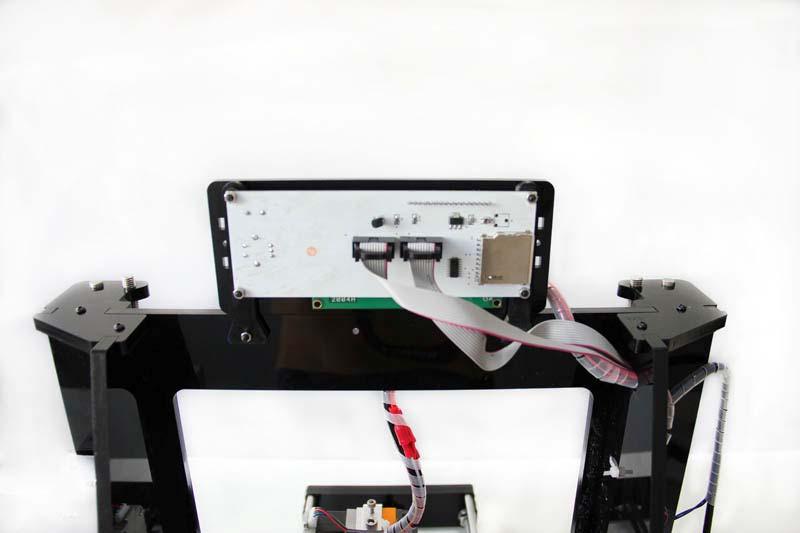
47 Mount the LCD panel frame. Required parts LCD 004 LCD frame LCD frame holder Acrylic washer M3 x 0 screw M3 nut NO.79 NO.A NO.A4 NO.A NO.7 NO.

48

49 Mount the filament spool. Shenzhen GETECH CO.,LTD Required parts Filament side panel M3 x 6 screw M3 square nut PVC tube NO.A7,8 NO.6 NO.6 NO.60,6 3 Mount the PSU Required parts PSU M4 x screw M3 x 0 screw M3 nut 4 NO.74 NO.33 NO.7 NO.

50 Power cable Shenzhen GETECH CO.,LTD NO.6 Mount the PSU on the right side panel with 4 M4 x screws. Then mount the AC socket with M3 x 0 screws. You have to take off one end of the connectors to get both the power button and the power socket into the hole.


51 . Mind the color of the wires. The wrong connection of the wire will cause serious damage to the PSU and even to the control board of the printer.


 These caps are very tiny; do not throw them away inadvertently.")
52 . Pay attention to the switch on the right side of the PSU, there are two options of voltage: 0 V and 0V, choose according the standard in your country. As shown in the following picture. 4 Mount the control board on the left side panel Here we take the Sanguinololu as an example. Step, plug the jumper caps on the following pins of the board. (In the yellow circle) These caps are very tiny; do not throw them away inadvertently. The jumper caps are packaged along with the board, do not lost them. You need to plug caps in all.

53 Step. Stack the 5 A4988 on Sanguinololu

54 Step3. Stick the heat sink on the chip of the 4 A4988.

55 Step4, connect all the wires to the interfaces of the board The referring wiring schematic diagram of Sanguinololu For more information about Sanguinololu, please visit the wiki page. Note: when connect the other Y-motor, use the 4-pin M-F DuPont cable and pay attention to the directions of the wire. If you connect them reversely, the Z motor will move in different directions. Look at the colors of the wire.


56 PS: The referring wiring schematic diagram of Ramps.4 For more information about ramps.4, please visit the ramps.4 wiki Step5. Mount the board on the left side panel of the printer. And cover the board with

57 the acrylic plate. Shenzhen GETECH CO.,LTD Required parts M3x0 screw 4 NO.7 M3 x 40 screw NO.30 M3 nut 4 NO. All the wires can be tied together under the printer, but you should make sure they don t touch the belt.

58 Arrange the wires and tidy up them with the coil. The whole printer assembly work is already done. Hope you enjoy the whole process.
Assembly Instructions of Geeetech Aluminum Prusa I3
 Assembly Instructions of Geeetech Aluminum Prusa I3 CONTENT Safety Instructions... 3 Preparation... 4 1. Unfold the box and check the package... 1 2. Assemble Y axis... 1 3. Build the printing platform...
Assembly Instructions of Geeetech Prusa I3 A pro
 Assembly Instructions of Geeetech Prusa I3 A pro (Version 04-11-2016) CONTENT Safety Instructions... 3 Preparation... 4 1. Unfold the box and check the package... 1 2. Assemble Y axis... 1 3. Build the
Building Instruction of Geeetech Prusa I3 pro W. 3D Printer
 Building Instruction of Geeetech Prusa I3 pro W 3D Printer Version 05-31-2017 Contents Safety Instructions... 2 Preparations... 3 1.Unfold the box and check the package... 4 2 Assemble the rods of a Y
Building Instructions of Geeetech Prusa I3 M201
 Building Instructions of Geeetech Prusa I3 M201 (Version 04-11-2016) CONTENT Safety Instructions... 1 Preparation... 2 1. Assemble the threaded rods of Y axis... 3 2. Assemble the front and back support
Building Instructions of Geeetech Prusa I3 M201
 Building Instructions of Geeetech Prusa I3 M201 (Version 11-25-2016) CONTENT Safety Instructions... 1 Preparation... 2 1. Assemble the threaded rods of Y axis... 3 2. Assemble the front and back support
Prusa i3 Printer Assembly Guide
 Prusa i3 Printer Assembly Guide Special thanks to Carlos Sanchez and Miguel Sanchez for the graphics. All graphics captured from their great animation: http://www.carlos-sanchez.com/ Prusa3/ For copyright
Copyright Declaration
 Geeetech Prusa I3 X Copyright Declaration The copyright of this manual belongs to the Shenzhen GETECH CO., LTD. (hereinafter referred to as the "Geeetech"), and all rights reserved. No part of this specification
Geeetech Prusa I3 M201
 Geeetech Prusa I3 M20 Copyright Declaration The copyright of this manual belongs to the Shenzhen GETECH CO., LTD. (hereinafter referred to as the "Geeetech"), and all rights reserved. No part of this specification
Geeetech Prusa I3 M201. Assembly Manual
 Geeetech Prusa I3 M20 Assembly Manual SUPPORT Thanks for choosing Geeetech, we strive to provide a satisfied and pleasant shopping experience for you, but we do understand there may be some questions you
Delta Rostock mini G2S Pro 3D Printer
 Delta Rostock mini G2S Pro 3D Printer Copyright Declaration The copyright of this manual belongs to the Shenzhen GETECH CO., LTD. (hereinafter referred to as the "Geeetech"), and all rights reserved. No
K Wiring and Electronics
 HKBay.com K Wiring and Electronics Written By: HKBay 2017 hkbay.dozuki.com Page 1 of 12 TOOLS: Hex key; ball ended, long arm, 2.5mm (1) PARTS: Arduino Mega (blue) (1) RAMPS board (red) (1) glass tabs (3)
5. E-axis assembly. 5. E-axis assembly. Written By: Jakub Dolezal manual.prusa3d.com/ Page 1 of 40
 5. E-axis assembly Written By: Jakub Dolezal 2018 manual.prusa3d.com/ Page 1 of 40 Step 1 Tools necessary for this chapter Needle-nose pliers for zip tie trimming. 2.5mm Allen key for M3 screws 2mm Allen
Modix Big-60 Assembly Manual Part 2
 Modix Big-60 Assembly Manual Part 2 Version 1.0, October 2017 Menu 1. Motors & End Stop Wiring... 3 2. Controller Wiring Check... 6 3. Extruder Wiring... 7 4. Electronic Box Cover... 9 5. Filament Sensor...
5. Extruder Assembly
 5. Extruder Assembly Guide for the assembly of the Extruder. Written By: Josef Prusa 2018 manual.prusa3d.com/ Page 1 of 24 Step 1 Get the necessary tools 2.5 and 1.5 mm Allen key Needle-nose pliers 2018
Maker's Tool Works. Written By: Micro. Wiring methods used by MTW Printers using the Rambo Electronics. Wiring Rambo Electronics & Power Supply
 Maker's Tool Works Wiring Rambo Electronics & Power Supply Wiring methods used by MTW Printers using the Rambo Electronics. Written By: Micro 2017 mtw.dozuki.com Page 1 of 10 TOOLS: Screw Drivers (1) Wire
8. Electronics assembly (B3/R2 design)
") 8. Electronics assembly (B3/R2 design) Written By: Jakub Dolezal 2018 manual.prusa3d.com/ Page 1 of 31 Step 1 Tools necessary for this chapter Needle-nose pliers for zip tie trimming. 2.5mm Allen key for
8. Electronics assembly (B3/R2 design) Written By: Jakub Dolezal 2018 manual.prusa3d.com/ Page 1 of 31 Step 1 Tools necessary for this chapter Needle-nose pliers for zip tie trimming. 2.5mm Allen key for
Electronics. Electronics docs.imade3d.com/ Page 1 of 15
 Electronics 2018 docs.imade3d.com/ Page 1 of 15 Step 1 Wire Comb 4" zip ties Wire comb Step 2 Align the wire comb with the corresponding annotations (ie. filament fan, heat block, etc.), and secure it
3. Extruder Assembly
 3. Extruder Assembly Guide for the assembly of the Extruder. Written By: Josef Prusa 2017 manual.prusa3d.com Page 1 of 22 Step 1 Get the necessary tools 2.5 and 1.5 mm Allen key Needle-nose pliers Step
Modix Big-60 Assembly Instructions Part 1
 Modix Big-60 Assembly Instructions Part 1 Version 1.0, October 2017 Menu 1. X Idler Pulley Assembly... 3 2. Connecting X Axis Brackets to Z Profiles... 4 3. Assemble X Rails on X Top Profiles... 6 4. Assemble
Pi Instruction Manual. Mechanical
 Pi3 2014 Instruction Manual Document No MANUAL WBS Pi3 2014 DIY REV01 Mechanical 3D LabteK Model 1 / 37 Content Page Introduction 2 Printed Parts 3 1, Mechanical 4 1,1 Frame Assembly 6 1,2 Y Axis Assembly
Written By: Josef Prusa
 7. PSU & Heatbed assembly PSU and Heatbed guide Written By: Josef Prusa 2017 manual.prusa3d.com/ Page 1 of 17 Step 1 Getting the necessary tools 2 and 2.5 mm allen key Needle-nose pliers Step 2 3D printed
3. X-axis assembly. 3. X-axis assembly. X axis guide. Written By: Josef Prusa manual.prusa3d.com/ Page 1 of 14
 3. X-axis assembly X axis guide Written By: Josef Prusa 2017 manual.prusa3d.com/ Page 1 of 14 Step 1 Getting the necessary tools 1.5mm & 2.5mm Allen key Needle-nose pliers Step 2 3D printed parts X-carriage
SeeMeCNC Guides. Orion Delta HE280 Hotend Upgrade. This How-to Guide will walk you through the steps of upgrading to the HE280 Hotend
 SeeMeCNC Guides Orion Delta HE280 Hotend Upgrade This How-to Guide will walk you through the steps of upgrading to the HE280 Hotend Written By: JJ Johnson 2017 seemecnc.dozuki.com Page 1 of 18 INTRODUCTION
How this (and most) 3D Printers work. Forward
 3D Printers work. Forward") Build Manual Contents Contents Contents 2 Forward 4 How this (and most) 3D Printers work. 5 3D Printing Workflow 6 Space to work 7 Tools / Parts Required 7 Build Time 8 How To Use This Manual 8 Acrylic
Build Manual Contents Contents Contents 2 Forward 4 How this (and most) 3D Printers work. 5 3D Printing Workflow 6 Space to work 7 Tools / Parts Required 7 Build Time 8 How To Use This Manual 8 Acrylic
Upgrade v3 to v3.2. SeeMeCNC Guides. Upgrade v3 to v3.2. Rostock Max v3 Uprgade to v3.2. Written By: SeeMeCNC seemecnc.dozuki.
 SeeMeCNC Guides Upgrade v3 to v3.2 Rostock Max v3 Uprgade to v3.2 Written By: SeeMeCNC 2018 seemecnc.dozuki.com/ Page 1 of 34 INTRODUCTION This guide is intended to Upgrade a Rostock Max v3 to a Rostock
ASSEMBLY MANUAL TINKERINE STUDIO. 3D Printer + Creative Solution
 + ASSEMBLY MANUAL 3D Printer + Creative Solution CONTENTS Safety Instructions Ditto at a Glance Bill of Materials Before You Start Z-Platform Ditto Frame pt.1 Ditto Frame pt.2 Gantry pt.1 Gantry pt.2 Gantry
Quick Starter Manual for PrusaM201
 Quick Starter Manual for PrusaM201 Copyright Declaration The copyright of this specification belongs to the Shenzhen GETECH CO., LTD. (hereinafter referred to as the "Geeetech"), and all rights reserved.
Important notice Upper supports for Z axis Pulley Corner for Y axis Right X axis and left X axis Chain coupling for left X axis
 Warranty and FAQ G004260 Important notice You can personalise your Prusa i3 HEPHESTOS and update it with the latest innovations that appear in the community. However, it is important that you understand
WANHAO Duplicator i3. User Manual V1.2. Wanhao USA
 WANHAO Duplicator i3 User Manual V1.2 Wanhao USA 2015 www.wanhaousa.com Safety WARNING: The components on the Duplicator i3 generate high temperatures and move extremely fast. Reaching inside of the Duplicator
UM3 Spare Parts Ultimaker 3 Spare-Parts Version /06/18
 Ultimaker 3 Spare-Parts Version 1.2 13/06/18 Housing 1156 Z-Shaft Cap Bottom 1901 Controler Electronics Cover 1902 Main Board Electronics Cover 1903 Cable Cover 1904 Wifi Cover 1905 Print Table Back Cover
M2 Wiring. Table of Contents
 M2 Wiring Table of Contents M2 Wiring Harness... 2 RAMBo... 3 Wire Harness 1... 4 Wire Harness 2... 5 Wire Harness 3... 6 Wire Harness 4... 7 Wire Harness 5... 8 Connecting Wiring Harness to M2 Printer...
Documentation version 1.42 ASSEMBLY INSTRUCTIONS REV 1.1
 Documentation version 1.42 ASSEMBLY INSTRUCTIONS REV 1.1 / 2 INTRODUCTION / 3 INTRODUCTION Target : Prupose a visual guide of the differents steps to build and use a µdelta printer Designers : Hugo Flye
Assembly Manual. 1/10th Formula 1 Car
 Assembly Manual 1/10th Formula 1 Car Center Pivot Bag 1 3374 - Center Pivot Socket 40194 - Hard Anodized Alum Pivot ball 3254-2-56 *Note - Sometimes it is helpful to slightly over-tighten the top clamp
2. Multiplexer assembly
 2. Multiplexer assembly Written By: Jakub Dolezal 2017 manual.prusa3d.com/ Page 1 of 15 Step 1 Parts identification Y-splitter (new version) - QSM fittings and steel tubes are assembled in the factory.
CONTENTS. Safety Instructions. Litto at a Glance. Bill of Materials. Before You Start. Z-Platform. Litto Frame pt.1. Litto Frame pt.2. Gantry pt.
 ASSEMBLY MANUAL CONTENTS Safety Instructions Litto at a Glance Bill of Materials Before You Start Z-Platform Litto Frame pt.1 Litto Frame pt.2 Gantry pt.1 Gantry pt.2 Gantry pt.3 Carriage Electronics /
TeeBox. The Suitcase 3D printer. BY:
 TeeBox The Suitcase 3D printer. BY: Eindhoven The Netherlands Contents Liability... 2 Returns... 2 WARNING... Error! Bookmark not defined. TRICKS AND TIP... 4 PART 1 ---Y AXIS (PRINT BED)... 7 Fasten heatbed
RJS2020 SPORT 3.2 1/10 PAN CAR KIT LESS ELECTRICS
 RJS2020 SPORT 3.2 1/10 PAN CAR KIT LESS ELECTRICS THANKS FOR BUYING THE RJ SPEED 1/10 SPORT 3.2 KIT. THE ASSEMBLY WILL NOT BE DIFFICULT IF YOU READ THE TEXT, LOOK AT THE PICTURES, AND THE EXPLODED VIEW
JGAURORA 3D PRINTER MODEL: A5 USER GUIDE
 JGAURORA 3D PRINTER MODEL: A5 USER GUIDE Contents ----3D Printer User Guide 1. Preface... 2 1.1 Introduction...2 1.2 Safety advice... 2 1.3 Filament requirements...2 1.4 Environmental requirements...2
Installation Instruction of CTC DIY 3D Printer
 Installation Instruction of CTC DIY 3D Printer Focus on high-end science and technology,focus on 3D printing Zhuhai CTC Electronics Co.,Ltd. www.ctcprinter.com 1 Introduction This DIY 3D printer can be
3D TOUCH. Extruder upgrade. Document version 1.0
 3D TOUCH Extruder upgrade Document version 1.0 1 Summary This manual is for the installation of an additional extruder into the 3D Touch. The procedure is the same for both 1 2 head, and 2 3 head upgrades.
Assembly Manual FELIX One
 Assembly Manual FELIX One Version 1.0 2018 www.felixprinters.com support@felixprinters.com Zeemanlaan 15 3401 MV IJsselstein The Netherlands Introduction Table of Content Dear Customer, Thank you for choosing
Procharger Stage II Intercooled Supercharger System (11-14 GT)
") Procharger Stage II Intercooled Supercharger System (11-14 GT) Installation Time: Approximately one day. Installed on 2012 Mustang GT 5.0/Manual Required Tools 3/8 Socket Set (Standard and Metric) 1/2
Procharger Stage II Intercooled Supercharger System (11-14 GT) Installation Time: Approximately one day. Installed on 2012 Mustang GT 5.0/Manual Required Tools 3/8 Socket Set (Standard and Metric) 1/2
TL4076 Top 5 Tips Get to know your TL4076
 TL4076 Top 5 Tips Get to know your TL4076 Thermal Break with Teflon liner (behind fan) Hot End Assembly Fan Heat Block Extruder with toothed gear(brass) and idler (steel) Filament Guide Tube Nozzle Cable
NORTHSTAR TRAILERS. Assembly Guide for SPORTSTAR II Trailer
 NORTHSTAR TRAILERS Assembly Guide for SPORTSTAR II Trailer Congratulations! You are the proud owner of a NORTHSTAR trailer. Please follow the instructions and steps in this manual for proper assembly.
Assembly Manual FELIX Tec 4
 Assembly Manual FELIX Tec 4 Version 5.2 2018 www.felixprinters.com support@felixprinters.com Zeemanlaan 15 401 MV IJsselstein The Netherlands Introduction Table of Content Dear Customer, Thank you for
5. Extruder. 5. Extruder. Extruder guide. Written By: Dozuki System manual.prusa3d.com Page 1 of 16
 5. Extruder Extruder guide Written By: Dozuki System 2017 manual.prusa3d.com Page 1 of 16 Step 1 Get the necessary tools 2.5, 2 and 1.5 mm hex spanner Needle-nose pliers Step 2 3D printed parts Extruder
HIGH FLOW COLD AIR INTAKE SYSTEM INSTALLATION INSTRUCTIONS D , D A
 HIGH FLOW COLD AIR INTAKE SYSTEM INSTALLATION INSTRUCTIONS D760-0320, D760-0320A 1992-95 325i, is 1995 M3 (3.0L) Parts List: 1 Intake Tube 1 Silicone Hose 1 Air Flow Meter Bracket 1 Hose Clamp (#36z) 1
1 Assembly of the Y axis
 1 ssembly of the Y axis Q yclone 1 Preparing the side frames. x1 x1 x6 x12 E Printed part for right side Printed part for left side o not fully tighten the screws so that you will be able to insert the
mk3 SEAT Ibiza Cupra Front Mount Intercooler.
 mk3 SEAT Ibiza Cupra Front Mount Intercooler. Warning be sure not to let any foreign body enter the inlet track of the vehicle whilst the following work is being carried out. Serious engine damage may
3D PRINTER USER MANUAL
 3D PRINTER USER MANUAL Table of contents page: 1. Introduction 2. Table of contents 3. Basic informations 4. General information 5. Glossary 6. Starter pack s content 7. Technical parameters 8. Device
GENUINE PARTS INSTALLATION INSTRUCTIONS
 GENUINE PARTS INSTALLATION INSTRUCTIONS 1. 2. 3. DESCRIPTION: APPLICATION: PART NUMBER: Accent light Kit Cube (MY2013+) 999F3 AW000 - Universal Accent Lighting Kit. 4. KIT CONTENTS: Item QTY Description
Documentation version ASSEMBLY INSTRUCTIONS
 Documentation version 1.1.0 ASSEMBLY INSTRUCTIONS / 2 INTRODUCTION / 3 INTRODUCTION Target : Provide a visual guide of the various steps required to assemble the «i3 Metal Motion» 3D printer. Designers
Installation instruction do88 Intercooler for SAAB 9-3SS/SC 2,8 V6 Turbo
 Installation instruction do88 Intercooler for SAAB 9-3SS/SC 2,8 V6 Turbo This instruction shows how to replace the OEM intercooler with this performance intercooler. At this type of installation we always
Porsche 928 with 16v LH-Jetronic Fuel System
 Porsche 928 with 16v LH-Jetronic Fuel System Toll-Free Tech Hot Line: 877-FOR-928M 877-367-9286 Please do not copy this manual and give copies to your friends. Our ability to bring you this supercharger
Table of Contents. Prusa i3 Build Manual
 Table of Contents Forward... 4 1. Y-AXIS Frame... 5 1.1 Y-AXIS Long Sections...6 1.2 Y-Axis Rear Section (Motor)...7 1.3 Y-Axis Front Section (Idler)...9 1.4 Y-Axis Lower Frame Completed...10 2. Z-AXIS
Dallas BEST 2014 Blade Runner
 Dallas BEST 2014 Blade Runner Software Training 1 Easy C software training If needed, get your 150day EasyC licence code at Rkit pickup. Must run as admin to install EasyC license. RobotC and Simulink
<THESE INSTRUCTIONS MUST BE GIVEN TO THE END USER> B&W Trailer Hitches 1216 Hawaii Rd / PO Box 186 Humboldt, KS P: F:
 B&W Trailer Hitches 26 Hawaii Rd / PO Box 86 Humboldt, KS 66748 P:620.473664 F:620.869.903 Turnoverball Gooseneck Hitch Installation Instructions Mounting
4 Assembly of Y axis
 4 ssembly of Y axis List of components for Y axis 2 x Ø 8 mm x 340 mm smooth chrome rod 2 x M10 x 370 mm threaded rod 4 x M8 x 205 mm black threaded rod 1 x M3 x 16 mm - DIN-912 class 8.8 black screw 6
<THESE INSTRUCTIONS MUST BE GIVEN TO THE END USER> B&W Trailer Hitches 1216 Hawaii Rd / PO Box 186 Humboldt, KS P: F:
 B&W Trailer Hitches 26 Hawaii Rd / PO Box 86 Humboldt, KS 66748 P:620.473664 F:620.473766 Turnoverball Gooseneck Hitch Installation Instructions Mounting
INSTALLATION INSTRUCTIONS SEMI Hidden Kit Part Number: Application: Toyota Tacoma
 INSTALLATION INSTRUCTIONS SEMI Hidden Kit Part Number: 100044 Application: 2016+ Toyota Tacoma GENERAL SAFETY PRECAUTIONS Your safety, and the safety of others, is very important. To help you make informed
rev 1_ XML02
 1 DECK, MOTOR, BLADE 2 1 DECK, MOTOR, BLADE 1 1 273675-0 GRIP A 1 1 2 266459-3 TAPPING SCREW 5X25 2 1 3 453250-0 LOCK LEVER 1 1 4 453251-8 LOCK LEVER SUPPORT 1 1 5 233173-6 COMPRESSION SPRING 4 1 1 6 144077-6
Bondtech for Prusa i3
 Bondtech for Prusa i3 Assembly and installation manual This work is licensed under a GNU General Public License v3.0 Table of Contents Acknowledgements 1 Introduction 1 Compatibility 2 What s in the box?
Documentation version ASSEMBLY INSTRUCTIONS
 Documentation version 1.6.30 ASSEMBLY INSTRUCTIONS / 2 INTRODUCTION / 3 INTRODUCTION Target : Propose a visual assembly instruction guide of the MicroDelta Rework. Designers of the MicroDelta Rework :
INSTALLATION INSTRUCTIONS `64 ½ - 70 MUSTANG, HEIDTS IFS, PRO-G GEN II P/N: MTF-201
 INSTALLATION INSTRUCTIONS `64 ½ - 70 MUSTANG, HEIDTS IFS, PRO-G GEN II P/N: MTF-201 Please read these instructions completely Before starting your installation. Assemble suspension on vehicle before powder-coating
3D PRINTER. Pack 09. Anything you can imagine, you can make! 3D technology is now available for you at home! BUILD YOUR OWN
 BUILD YOUR OWN Pack 09 Anything you can imagine, you can make! 3D PRINTER Compatible with Windows 7 & 8 Mac OS X 3D technology is now available for you at home! www.model-space.com BUILD YOUR OWN 3D PRINTER
NORTHSTAR TRAILERS. Assembly Guide for MULTISTAR Trailer
 NORTHSTAR TRAILERS Assembly Guide for MULTISTAR Trailer Congratulations! You are the proud owner of a NORTHSTAR trailer. Please follow the instructions and steps in this manual for proper assembly. TRAILER
Head Lamp Installation Guide
 Head Lamp Installation Guide This document explains the steps that need to be performed to ensure precise installation of the Jaguar XK Projector headlight system. Step 1: Remove the existing head lights
Pitch Stop Mount Support for WRX/STI
 Pitch Stop Mount Support for 2015+ WRX/STI 2017-02-06 Thank you for purchasing this PERRIN product for your car! Installation of this product should only be performed by persons experienced with installation
TOP AND CONSOLE PARTS For Models: YWED9400SW1, YWED9400SZ1, YWED9400SU1 (White/Chrome) (White/Blue) (Ultimate Silver)
 (White/Blue) (Ultimate Silver)") TOP AND CONSOLE PARTS ELECTRIC DRYER 3 08 Litho in U.S.A. (L.T.) 1 Part No. Rev. A TOP AND CONSOLE PARTS 1 Literature Parts W10151591 Use & Care Guide W10177461 Tech Sheet W10111226 Guide, Quick Start
TOP AND CONSOLE PARTS ELECTRIC DRYER 3 08 Litho in U.S.A. (L.T.) 1 Part No. Rev. A TOP AND CONSOLE PARTS 1 Literature Parts W10151591 Use & Care Guide W10177461 Tech Sheet W10111226 Guide, Quick Start
Maintenance Manual. Hephestos
 Hephestos 2016 Mundo Reader SL. All rights reserved. The reproduction, copying, distribution, publication or modification of this material is strictly prohibited unless carried out with the express prior
Installation instruction do88 Intercooler for SAAB 9-3SS/SC 4-cyl Turbo
 Installation instruction do88 Intercooler for SAAB 9-3SS/SC 4-cyl Turbo This instruction shows how to replace the OEM intercooler with this performance intercooler. 1. 4. 5. At this type of installation
Introduction Frame assembly Y axis assembly X axis assembly Z axis assembly Heated bed assembly Extruder drive assembly
 RepRapPro Huxley - RepRapWiki http://reprap.org/wiki/reprappro_huxley RepRapPro Huxley From RepRapWiki Introduction Frame assembly Y axis assembly X axis assembly Z axis assembly Heated bed assembly Extruder
Lexus ES Fine Mesh and Adaptive Cruise Control Fine Mesh Grilles Upper and Lower Replacements
 IMPORTANT: PLEASE KEEP THIS INSTRUCTION MANUAL FOR FUTURE REFERENCE! 2013-15 Lexus ES Fine Mesh and Adaptive Cruise Control Fine Mesh Grilles Upper and Lower Replacements Part #1372-0102-13 / Black Ice
STOP---READ THIS FIRST!
 STOP---READ THIS FIRST! **Read These Entire Instructions Before Starting Anything** 2003-2013 DODGE Ram 2500/3500, 8 LIFT KIT NOTE: * The factory wheels and tires WILL fit on the front of the vehicle once
Physics 144 Chowdary How Things Work. Lab #5: Circuits
 Physics 144 Chowdary How Things Work Spring 2006 Name: Partners Name(s): Lab #5: Circuits Introduction In today s lab, we ll learn about simple electric circuits. All electrical and electronic appliances
Please read the safety instructions carefully before get started.
 Safety Instructions Please read the safety instructions carefully before get started. ANYCUBIC 3D printer generates high temperature. Do not reach inside of the printer during operation. Allow time for
TOP AND CONSOLE PARTS
 TOP AND CONSOLE PARTS ELECTRIC DRYER 1 08 Litho in U.S.A.(LT) 1 Part No. Rev. B TOP AND CONSOLE PARTS 1 Literature Parts W10110850 Use & Care Guide W10110638 Tech Sheet W10111226 Guide, Quick Start 2 3980634
Illustrated Parts & Packing List 815 Rice Lake Street, Owatonna, MN For a complete distributor & dealer list go to
 Illustrated Parts & Packing List 815 Rice Lake Street, Owatonna, MN 55060 For a complete distributor & dealer list go to www.gandy.net 6250BN36C Orbit-Air Applicator 50 Cu. Ft. Hopper w/ 26 (1-1/4 ) Openings,
J & D Machine / Hyperdrive / MSA 3711 Moon Bend Rd. Chapel Hill, TN 37034
 J & D Machine / Hyperdrive / MSA 3711 Moon Bend Rd. Chapel Hill, TN 37034 www.hyperdriveracing.com 1 You now own a state of the art 1/10 scale oval race car. The Hyperdrive Assault has gone through months
This LED flashtube kit covers models 400, 404, 500, 504, 600, 680 & 506.
 L.E.D. INSTRUCTIONS I D T S O T U B I R M O C R Y N A P Kit contains: This LED flashtube kit covers models 400, 404, 500, 504, 600, 680 & 506. For the power supply: 1-LED power supply circuit board, 2
MKVI Jetta Fog Light Kit
 MKVI Jetta Fog Light Kit Part Number VW Jetta Fog Light Installation This tutorial is provided as a courtesy by ECS Tuning. Proper service and repair procedures are vital to the safe, reliable operation
6. Pre-print checks. 3D Touch
 Page 1 1. 6. Pre-print checks........................................................................................... 1.1 a. Clearing the print bed..................................................................................
Step-by-Step Instructions for ieq45 R.A. Worm Installation/Replacing September 2013
 Step-by-Step Instructions for ieq45 R.A. Worm Installation/Replacing September 2013 These instructions serve to explain how to Replace a R.A. worm; Adjust a RA worm/wheel meshing; Inspect and clean a RA
Factory Five Racing, Inc. 818 Kit Assembly manual revision 1i update
 Factory Five Racing, Inc. 818 Kit Assembly manual revision 1i update Pedal box...1 Cable Accelerator Pedal (2002-2005)...2 OEM seats...7 Windshield... 13 Center console... 19 Pedal box Attach the pedal
Installation instruction do88 Intercooler for SAAB 9-3 1,9 TTiD
 Installation instruction do88 Intercooler for SAAB 9-3 1,9 TTiD This instruction shows how to replace the OEM intercooler with this performance intercooler. At this type of installation we always recommend
Permanent Magnetic Linear Generator Project Prototype (This Material was Produced by Oregon State University s Energy Systems Group)
") Permanent Magnetic Linear Generator Project Prototype (This Material was Produced by Oregon State University s Energy Systems Group) This Permanent Magnet Linear Generator (PMLG) prototype was developed
Permanent Magnetic Linear Generator Project Prototype (This Material was Produced by Oregon State University s Energy Systems Group) This Permanent Magnet Linear Generator (PMLG) prototype was developed
Athletic Field Painting Pointers Line Star Drawing Line Star Parts List 3-4. Spray Boom Drawing Stainless Steel Tank 6
 TABLE OF CONTENTS TITLE PAGE Athletic Field Painting Pointers 1 44-508 Line Star Drawing 2 44-508 Line Star Parts List 3-4 Spray Boom Drawing 5 40-127 Stainless Steel Tank 6 4085 Spray Gun 7 40-153 Gun
S1 Sequential. T56 Magnum. Sequential shifter. Contents and assembly instructions
 S1 Sequential Sequential shifter T56 Magnum Contents and assembly instructions Parts List Sequential shifter x1 Base plate x1 Base spacer x1 Drill Square x1 Shaft fitting x1 Square washer x1 8mm Aluminium
INSTALLATION INSTRUCTIONS
 Accessory Application Publication No. INSTALLATION INSTRUCTIONS WINCH MOUNT KIT P/N 08L77-HL3-A00 SXS700M4/M2 Honda Dealer: Please give a copy of these instructions to your customer. MII 14607 Issue Date
Shown with optional GFR-1017R Body Posts. J & D Machine / Hyperdrive / MSA 3711 Moon Bend Rd. Chapel Hill, TN
 Shown with optional GFR-1017R Body Posts J & D Machine / Hyperdrive / MSA 3711 Moon Bend Rd. Chapel Hill, TN 37034 www.hyperdriveracing.com 1 You now own a state of the art 1/10 scale oval race car. The
TABLE OF CONTENTS INTRODUCTION 3. INSTALLATION PROCEDURES Air Conditioner Location 4. A/C Ducting Installation 5
 585474 1 TABLE OF CONTENTS SECTION PAGE INTRODUCTION 3 INSTALLATION PROCEDURES Air Conditioner Location 4 Air Conditioner Mounting 4 A/C Ducting Installation 5 Power Kit Installation (Batteries). 5 Separator...
Bosch Seat Motor _spec_sheet_-_Bosch_FRC_motor_6_004_.pdf. FRC_Bosch_motor_V2_6_004_RA3_ zip
 Bosch Seat Motor Specification Sheet 2016-12-21_spec_sheet_-_Bosch_FRC_motor_6_004_.pdf CAD File FRC_Bosch_motor_V2_6_004_RA3_194-06.zip Motor Mounting & Shaft Support: Suggested Motor relies on two solid
2014 GM 1500 TRUCK STOP---READ THIS FIRST! 7" Lift KIT. **Read These Entire Instructions Before Starting Anything**
 STOP---READ THIS FIRST! **Read These Entire Instructions Before Starting Anything** 2014 GM 1500 TRUCK LIFT KIT INSTRUCTIONS (PART #50768 & #50769 ) 5680 W. Barstow, Fresno, CA 93722 PH: (559) 226-8196
INSTALLATION INSTRUCTIONS Chevrolet Nova Superide II Independent Front Suspension
 INSTALLATION INSTRUCTIONS 1962 1967 Chevrolet Nova Superide II Independent Front Suspension Please read these instructions completely before starting your installation. Assemble suspension on vehicle before
Graphical representation of a gear
 Homework 4 Gears Gears are designed to transmit rotary motion. Often they are arranged in a gear train (meshed together). Gear trains provide a change in speed, torque (turning force) and direction (clockwise
Rostra Electronic Cruise Control Install On a Stratoliner or Roadliner
 Rostra Electronic Cruise Control Install On a Stratoliner or Roadliner MATERIALS LIST: 1 - Rostra Part # 250-1223 (www.brandondist.com/products/cruise1223.htm) 1 - Signal Splitter part # 250-4369 1 - Engagement
DL650 Odyssey Luggage Installation Guide
 DL650 Odyssey Luggage Installation Guide Thank you for purchasing Jesse Luggage for your Motorcycle. Our Luggage, handcrafted in the USA, is designed for those with an interest in finding the most durable
OIL COOLER KIT INSTALLATION INSTRUCTIONS PART NUMBER D
 OIL COOLER KIT INSTALLATION INSTRUCTIONS PART NUMBER D570-0904 APPLICATION: 2011-2012 E90 335i/xi (N55 engine) with BMW standard bumper and with stock oil cooler Congratulations for being selective enough
To be the Chief Evangelist CR-10S Pro Printer Guide Book To make Top-quality 3D printer
 To be the Chief Evangelist CR-0S Pro Printer Guide Book To make Top-quality 3D printer This guide book is for standard CR-0S Pro. Please plug the power cord into a three-hole power jack. Detailed instructions
\ \ ~, en ~ \ \\ en I- ( \\\ b3~(i 5/27/93. æ Lr PECULIAR HYDRAULICS W LL BELT DRIVE, SLC,
 DODGE V8-38\360 W-W/O AC W/SERPENTINE 99-9 PECULIAR HYDRAULICS BELT DRIVE, SLC, UNDERHOOD VALVE 7505 ~., ( \\\ \ \\ ~,/./ LL a: :: z en ~ en I- W LL æ Lr ~,. \ \ \ "',: e /' ~ '\ '- -- - /' "-.. -- - -..