Quick Starter Manual for PrusaM201
|
|
|
- James Hensley
- 6 years ago
- Views:
Transcription

1 Quick Starter Manual for PrusaM201
2 Copyright Declaration The copyright of this specification belongs to the Shenzhen GETECH CO., LTD. (hereinafter referred to as the "Geeetech"), and all rights reserved. No part of this specification should be reproduced or extracted in any forms or means without the prior written consent of Geeetech by any company and individuals. Technical Support If you are interested in the technology of 3 D printing, flight control and U-home, welcome to Geeetech, we have series of made-up products, main boards, modules and a variety of peripherals for you. Or if you are looking for relevant information or technical support, please login our forum where you can find anything you want about open source. To know more about our new products, please visit we will serve you wholeheartedly.
3 Contents Quick Starter Manual for PrusaM Copyright Declaration...2 Technical Support... 2 Contents Install USB Driver Download and install Repetier-Host Repetier-Host setting Function test Homing Directions of X, Y, Z motor Heating Extruder LCD Heat bed leveling Slice 3r setting Import STL files Slicing Introduction of new function Mixer...29 Print alternating color Blending color...33 Gradient color Introduction of customizable gradient template Parameters Setting Instructions: Custom Template Setting Printing Effect Demonstration Introduction of Printer Settings FAQ... 46

4 1 Install USB Driver ShenZhen GETECH CO.,LTD 1.1 Windows update will automatically update and install the driver. Connecting USB, and there is a prompt in the bottom right corner of desktop, showing that the driver is installing the device driver software. 1.2 If your computer can t install the driver automatically, please manually install the driver according to following method. Download the USB driver and click installation. 2 Download and install Repetier-Host Download and install Repetier-Host. Please choose the corresponding version of Windows/Mac/Linux according to your operating system. Windows: After installation, open Repetier-Host. For starters, you can read following link to get information about how to use Repetier-Host

5 3 Repetier-Host setting ShenZhen GETECH CO.,LTD Before printing, please set following parameters. Click the Printer Settings, and the interface of printer setting will appear. Set following parameters in printer settings 1. Connection Choose the right printer port, Baud rate and Receive Cache Size. For other settings please choose the default parameter, and then click Apply. Port: correspondence with the port in device manager Baud Rate: Receive Cache Size:

6 2. Printer Set the printer s moving speed in direction of X, Y and Z axis. For other settings please choose the default parameter, then click Apply

7 3. Extruder Set the number of extruder as 2, and set the nozzle diameter. For other settings please choose the default parameter, then click Apply. You need set the nozzle diameter according to the diameter of extruder head you purchased. If you can t confirm the diameter, please contact the manufacturer to get right parameter

8 4. Printer shape Set home position and printing platform parameters. Printer type:choose Classic Printer - 5 -

9 After successfully finishing the printer settings, click the Connect in the top left corner. If the icon turns green, it means the printer is successfully connected with upper computer
10 4 Function test When upper computer is successfully connected, don t print immediately. You should test each part of the printer to see if they can work normally. Following picture is the manual control panel of upper computer - 7 -
11 Tests you should do are as following: 4.1 Homing Separately set X, Y and Z axis as zero, and three coordinate axes will move to the direction of endstop. At this moment please observe if the homing direction is right or not. If it is not right, please refer to FAQ. Home X: X axis moves to home position Home Y: Y axis moves to home position Home Z: Z axis moves to home position :means X, Y and Z axis simultaneously moves to home position

12 4.2 Directions of X, Y, Z motor Click the arrows in the icon to test if the directions of X, Y and Z motor are right. If the direction is reversed, please modify the logic value of corresponding motor. For specific solution, please refer to FAQ
13 4.3 Heating Here you can set the heating temperature of heat bed and extruder. Temperature of extruder can not be set too high or too low, otherwise the extruder can easily have blockage. You need adjust the temperature according to your filament. Generally speaking, PLA:extruder /heat bed:55 ABS:extruder / heat bed:75-80, In order to make the filament stick on the heat bed easily, please add ABS glue on the printing platform. Notice: we set the number of extruder as 2, but actually there is only one nozzle. When you are heating extruder 1, extruder 2 is also heated by default. Therefore, you don t need
14 simultaneously heat extruder 1 and 2. ShenZhen GETECH CO.,LTD If you can t heat extruder or heat bed, please refer to FAQ. At this moment, heat bed, extruder 1 and extruder 2 are separately heated up to 55 and Extruder After the extruder reaches the preset temperature, we need to make sure filament0 and filament1 are both working. Notice: At any time, please make sure that filament 0 and filament 1 are simultaneously inserted into the nozzle. Don t only insert filament 0 or filament 1. Otherwise, once no matter which kind of filament

15 is fused too much, it will overflow upwards and then block the hole through which the other kind of filament enters the heating block from the barrel. No matter in the process of cleaning filament or inserting and removing the filament, don t insert or remove the feeding pipe near the hot end. Once the filament in it is fused too much and feeding pipe is not inserted entirely, the fused filament will overflow up and then cause blockage. If this kind of problem happens, it will be difficult to clean the filament
16 Test extruder 1 ShenZhen GETECH CO.,LTD Click the downward arrow to test if filament 0 can be discharged fluently. In order to avoid blockage, please extrude filament at 1mm or 0.1 mm. You can use one hand to hold the filament, and it will be helpful for you to know the conditions of the rotation of extruder motor and moving of filament

17 If filament can t be extruded fluently or there is blockage, you will hear a sound of clicks. Please refer to FAQ

18 Choose extruder 2, repeat the steps of extruder 1. And test if filament 1 can be extruded fluently

19 4.5 LCD You can also test if these functions are normal or not through LCD. Enter LCD>Prepare

20 In the menu of prepare, you can do 6 kinds of operations including Disable steppers/auto home/preheat PLA/ Preheat ABS/Cool down/move axis. Followings are explains for each of them. 1. Disable stepper: X,Y, Z motor unlocking. When the motor is unlocked, X, Y and Z axis can be moved manually. 2. Auto Home: three axes move to home position at the same time 3. Preheat PLA:extruder and heat bed are separately heated to preset temperature: 200,
21 4. Preheat ABS: extruder and heat bed are separately heated to preset temperature: 240,95. You can also enter LCD<control<temperature<preheat PLA conf to modify the preset temperature. Set the preset temperature of extruder and heat bed. If you want to stop heating, please enter control<temperature and manually adjust the temperature to
22 5. Move axis X,Y,Z axis can move at a resolution of 10mm, 1mm and 0.1mm. Extruder 1 and extruder 2 can only move at a resolution of 1mm and 0.1mm. 5 Heat bed leveling You need do leveling for nozzle and four corners of the heat bed. Next is one of the leveling methods. Rough adjustment There is a Z axis endstop trigger (M3*50 screw) on the left end of X axis. Tightness of the spring determines the reset position of the Z axis. Through adjusting M3*50 screw, try to make the reset position of Z axis the same with the position where the extruder head exactly stops on the heat bed

23 Fine adjustment of the relative location between extruder head and heat bed 1. Set Z axis to initial position 2. After unlocking the motor, manually move X axis and Y axis, and move the extruder to four corners of the heat bed in turn. Because of former rough adjustment, the extruder head is very close to the heat bed. 3. Put a piece of flat A4 paper in the inter space between extruder head and heat bed, then drag the paper to test if there is a slight resistance. If there is, it means the extruder head is already at the right position. If not, you need adjust the screw of this corner of the heat bed to slightly raise or lower the heat bed


24 4. Move the extruder head to other three corners, and adjust their corresponding screws. 6 Slice 3r setting Following setting is just for reference, you need set different slicing parameters according to actual printing models and filament. 6.1 Import STL files You can download here

25 After successful import, if you need, you can do operations on the items in object placement including placing it in the middle/enlarging it/rotating it

26 6.2 Slicing Click slicer>configuration, slicer3r window will prompt up

27 Click file>load config in the top left corner,and import M201 slicing configuration. Download it here

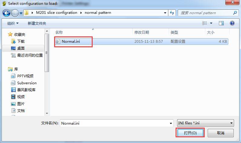
28 Import Normal.ini slicing configuration


29 After successfully importing Normal.ini slicing configuration, click save in print settings label. Set filament parameters in filament settings, and click save. Notice: please check Keep fan always on and Enable auto cooling in the tab of cooling. This is for avoiding blockage


30 In the tab of printer settings After you saving above slicing configuration, return to slicer Click the drop-down box of print settings/printer settings/filament settings, the slicing configuration which was just save as Normal.ini will appear. Choose this slicing parameters, and click slice with slic3r to do slicing for imported printing model

31 In the process of slicing

32 When slicing is finished, click print to begin printing. 7 Introduction of new function 7.1 Mixer Mixer is used to adjust the mixing proportion of two kinds of filaments in order to realize the

33 printing effect of different colors and blending colors. There is a menu in Mixer shown as following list: Prepare used for returning to upper Prepare Menu Filament 0: displaying current proportion of Filament 0. Press to enter, the value can be adjusted. Filament 1: displaying current proportion of Filament 1. Press to enter, the value can be adjusted. Note: extruder 1 is corresponding to filament 0, extruder 2 is corresponding to filament 1 The sum of the proportion of Filament 0 and Filament 1 is 100%. If you manually adjust either of the two values, system will automatically work out the other value. The proportion will not change unless you readjusting it or choosing template again. OFP: Over Fusion Protect. Through restricting the proportion of filaments, OFP can avoid blockage caused by the long-time stay in the extruder and over fusion carbonization of the two kinds of filaments. It can also avoid bad printing effects brought by filament s over-softness after over-fusion. This function is turned on by default. When it is turned on, the maximum proportion of filament is no more than 96%, and the minimum proportion is not less than 4%
34 You can also modify the OFP proportion OFP Max: maximum proportion of filament feeding OFP Min: minimum proportion of filament feeding Store Memory: save If it is not saved, the printer will agree that current parameters are valid. After restarting the printer, last setting is recovered. Templates: Menu entrance of blending template. Used for the storage of blending templates. The following is Templates menu. Templates are used for printing gradient color effect. Template 1: Once this template is chosen, Filament 1 will change to Filament 0 within the height of 2mm; Template 2: Once this template is chosen, Filament 0 will change to Filament 1 within the height of 2mm; Template 3: Once this template is chosen, Filament 0 will change to Filament 1 within the height of 10mm; Template 4:Once this template is chosen, Filament 1 will change to Filament 0 within the height of 10mm; Template 5:Once this template is chosen, Filament 0 will change to Filament 1 within the height of 20mm; Template 6:Once this template is chosen, Filament 1 will change to Filament 0 within the height of 20mm; Template 7:Once this template is chosen, Filament 0 will change to Filament 1 within the height of 50mm; Template 8:0nce this template is chosen, Filament 1 will change to Filament 0 within the height of 50mm; Both of manual adjustment and choosing template can change the blending proportion. It will come

35 into effect immediately and the proportion is determined by the last operation. Print alternating color You can use M201 to print alternating color like using other printers with dual extruders. Please calculate the printing time in advance, and adjust the proportion of filament 0 and filament 1 when it is time to change color. Method 1: Change filament 0:96%, filament1:4% to filament 0:4%,filament 1:96%,and this is changing from filament 0 to filament 1. Method 2: Select template 1, switch from filament 0 to filament 1 Select template 2, switch from filament 1 to filament
36 Blending color Manually adjusting the proportion of filament 0 and filament 1 can realize different blending colors

37 Gradient color Choose LCD<MIXER<Templates, and there are 4 pairs, 8 kinds of gradient colors for choosing. Following pictures are separately corresponding to the gradient effects from template 1 to template 8. You can change the template you want to use at any time and any stage

38 7.2 Introduction of customizable gradient template Custom template allows user to set the parameters of gradient color printing. It provides six customizable templates for user to set and they are named as Custom1 to Custom6. User can set
39 under the Mixer >Custom menu. Each template includes parameters of Start Gradient Percent, End Gradient Percent, Start Height, and End Height. Perform a Store Memory to Save it when the setting is done. Next i will show you how to set and use a customized template Parameters Setting Instructions: 1. All the settings are set based on Filament0 by default. 2. According to the work principle of Mixer, the sum feeding rate of Filament0 and Filament1 is 100%. After Filament0 is set, the system will automatically calculate the corresponding feeding rate of Filament1. 3. Start percent and end percent can be set at will. The sum of them is not always 100%. Users can adjust it according to their requirements. E.g., you can set the start percent of Filament0 as 30% and the end percent 60%. Filament0 Filament1 Total Start percent 30% 70% 100% End percent 60% 40% 100% Total 90% 110% 4. Start height and end height are print heights above the bed not the current printing height. Start height and end height must be greater than current printing height, otherwise they will be regarded as invalid. For example, current height is 40mm above the bed, but the start height in the template setting is 20mm and the end height is 30mm. It has overlapped part with current print height, so the system will automatically ignore this template and continue printing with the current template. 5. When one templates is finished, printing will continue with the feed rate percent that is fixed, without gradient effect, until you choose a new template Custom Template Setting

40 1 Open Mixer->Custom on LCD control panel: ShenZhen GETECH CO.,LTD Let s take custom 1 as example. Here we set custom 1 conf as follows: Start Percent: 30%

41 End Percent: 60% ShenZhen GETECH CO.,LTD Start Height: 0mm End Height: 30mm When the setting is done, please press Store memory to save it: Similarly you can set other custom templates, for example, custom 2: Start Percent: 60% End Percent: 20% Start Height: 30mm End Height: 60mm (note, there is no overlapped height)
42 The templates which have been set can be found in Mixer->Templates. You can change setting parameters at any time during the printing process. When the setting is done, you can start printing. Select the corresponding template in Mixer-> Templates during the printing process. Note: the * after the template means the current template you are choosing and using. System will follow your last chosen operation by default Printing Effect Demonstration The following picture shows the printing effect after the combination of Custom1 and Custom2. Filament 0: red; Filament 1: yellow

43 7.3 Introduction of Printer Settings Printer Settings is used to adjust some parameters of the printer and save them through Store memory. Choose LCD<control<printer settings
44 1. Set the printing volume of the printer X Max: 280 // X Max refers to maximum coordinate of X axis X Min: 0 // X Min refers to minimum coordinate of X axis Y Max: 210 // Y Max refers to maximum coordinate of Y axis Y Min: 0 // Y Min refers to minimum coordinate of Y axis Z Max: 200 // Z Max refers to maximum coordinate of Z axis Z Min: 0 // Z Min refers to minimum coordinate of Z axis
45 You can set the printing volume of the printer through above parameters. When setting is finished, choose Control<store memory to save the parameters. 2. Set home position Home X: MIN //Home X refers to the position of X axis after homing, and it can be set as Max

46 or Min Home Y: MIN Max or Min Home Z: MIN Max or Min ShenZhen GETECH CO.,LTD //Home Y refers to the position of Y axis after homing, and it can be set as //Home Z refers to the position of Z axis after homing, and it can be set as Notice: under normal conditions, the homing position is set as Min by default. Please don t modify this parameter at will. You can set the homing position of the printer through above parameters. When setting is finished, choose store memory to save the parameters. 3. Set motor direction X Motor Dir: False // X Motor Dir refers to the running direction of X motor

47 Y Motor Dir: True Z Motor Dir: True E Motor Dir: True E1 Motor Dir: True ShenZhen GETECH CO.,LTD // Y Motor Dir refers to the running direction of Y motor // Z Motor Dir refers to the running direction of Z motor // E Motor Dir refers to the running direction of E0 motor // E1 Motor Dir refers to the running direction of E1 motor Above setting is the default setting of M201. If you find your motor direction is reversed, you can change the motor direction through modifying this logic value. 4. Set endstop logic level
48 Logic level refers to logic active level Status refers to on/off state of endstop, NO (Normally Open), NC (Normally Close)
49 endstop of M201 is set by default as: Logic level: High Status: NC ShenZhen GETECH CO.,LTD 5. Print speed setting. Rotate the knob can adjust the printing speed during printing. It is 100% as default. 8. FAQ 1. Homing direction or motor direction is reversed. If you have this problem, please modify the logic value of corresponding motor in the menu of control>printer settings of LCD. Change the motor direction of corresponding axis from True to False or change it from False to True. 2. Instruction for the heating of extruder 2 In Repetier-Host, we set the number of extruder on M201 as 2, which means there are 2 extruder motors but only one hot end. You don t need simultaneously heat extruder 1 and extruder 2. Extruder 2 is heated by default when extruder 1 is heated
50 3. Extruder can t be heated For this problem, please check following electronic components 1) If the power supply works normally. 2) If there is a poor contact between the heating wire and the socket of control board. You should make the copper wire in the heating wire have a good contact with the cooper sheet of the socket. 3) There is an open circuit in somewhere of the hot end and heating wire (resistance is infinite), which causes no current passing through. 4) MOSFET may be burned-out. 4. Extrusion is not fluent or blockage problem 1) Whether the temperature setting of printer is proper or not. There are different melting temperatures of different filaments, and please choose proper heating temperature. Filament is easy to get carbonized when the temperature is too high; while the extrusion of filament will become less fluent when the temperature is too low. 2) The hot end cannot dissipate heat in time. Maybe this is because the fan wire of the hot end has a poor contact with the socket, which causes the fan of hot end stopping working. 3) The inter space between the nozzle tip and heat bed is too small, and this causes difficult extrusion. In order to get a proper space you can do like this: after z axis going back to home position, put an A4 paper between the nozzle and the heat bed and you can slide the paper under slight resistance. 4) The filament faces a large resistance in the path from the extruder to the nozzle. The resistance may be produced by the motor, feeding pipe or nozzle. 5) The torsion of the extruder motor is insufficient. You can adjust the potentiometer on A4988 to enhance the current. If there is blockage, please refer to following steps to solve it. 1) Heat the extruder to the temperature of the melting point of the filament. 2) Press the lever of the extruder motor and pull out the filament. If the filament is broken in the feeding pipe, please refer to step
 When you are inserting or pulling out the feeding pipe which is close to the hot end, it is easy to block the nozzle completely if your operation is not proper. Please mind your operation.")
51 3) Check the filament which has been taken out. If it has a sign of being slightly broken, please cut it off and reinsert the filament. 4) When you are inserting or pulling out the feeding pipe which is close to the hot end, it is easy to block the nozzle completely if your operation is not proper. Please mind your operation. Mark the current inserting depth of the feeding pipe in the barrel. Press the blue quick plug above the barrel and pull out the feeding pipe. Clean out the filament which is stuck in the pipe, then reinsert feeding pipe. Please notice that the depth of inserting the pipe should be the same with before. If the depth of inserting is shallower than before, melted filament will overflow upwards and takes up the place of feeding pipe, which makes the filament harder to enter the nozzle. 5) If you find too much filament gets accumulated in the hot end, please use needle to clean out surplus filament. Then reinsert feeding pipe and filament. This process doesn t need too much strength; otherwise the PTFE in the barrel will easily be stuck to broken

52 If you still have any problem, please turn to our forum for help. Our tech support will help you resolve them
Geeetech Prusa I3 M201
 Geeetech Prusa I3 M20 Copyright Declaration The copyright of this manual belongs to the Shenzhen GETECH CO., LTD. (hereinafter referred to as the "Geeetech"), and all rights reserved. No part of this specification
Geeetech Prusa I3 M201. Assembly Manual
 Geeetech Prusa I3 M20 Assembly Manual SUPPORT Thanks for choosing Geeetech, we strive to provide a satisfied and pleasant shopping experience for you, but we do understand there may be some questions you
Copyright Declaration
 Geeetech Prusa I3 X Copyright Declaration The copyright of this manual belongs to the Shenzhen GETECH CO., LTD. (hereinafter referred to as the "Geeetech"), and all rights reserved. No part of this specification
Delta Rostock mini G2S Pro 3D Printer
 Delta Rostock mini G2S Pro 3D Printer Copyright Declaration The copyright of this manual belongs to the Shenzhen GETECH CO., LTD. (hereinafter referred to as the "Geeetech"), and all rights reserved. No
Introduction to 3D Printing
 TAKE HOME LABS OKLAHOMA STATE UNIVERSITY Introduction to 3D Printing by Sean Hendrix 1 OBJECTIVE The objective of this experiment is to introduce you to 3D printing, by having you print some simple parts
JGAURORA 3D PRINTER MODEL: A5 USER GUIDE
 JGAURORA 3D PRINTER MODEL: A5 USER GUIDE Contents ----3D Printer User Guide 1. Preface... 2 1.1 Introduction...2 1.2 Safety advice... 2 1.3 Filament requirements...2 1.4 Environmental requirements...2
Please read the safety instructions carefully before get started.
 Safety Instructions Please read the safety instructions carefully before get started. ANYCUBIC 3D printer generates high temperature. Do not reach inside of the printer during operation. Allow time for
Building Instructions of Geeetech Prusa I3 M201
 Building Instructions of Geeetech Prusa I3 M201 (Version 11-25-2016) CONTENT Safety Instructions... 1 Preparation... 2 1. Assemble the threaded rods of Y axis... 3 2. Assemble the front and back support
Witbox 2. Quick start guide
 Witbox 2 Quick start guide Welcome. Thank you for choosing us. This manual will help you to use your new 3D printer correctly. Welcome to the world of Witbox 2. How do I use this manual? To make sure that
NWA3D A5 User Manual
 1. NWA3D A5 3D Printer Part Diagrams 2. Assembling the Spool Holder 3. Leveling the Build Plate 4. Loading and Unloading Filament 5. Operation: The Four Steps in 3D Printing 6. Troubleshooting 7. Additional
6. Pre-print checks. 3D Touch
 Page 1 1. 6. Pre-print checks........................................................................................... 1.1 a. Clearing the print bed..................................................................................
TL4076 Top 5 Tips Get to know your TL4076
 TL4076 Top 5 Tips Get to know your TL4076 Thermal Break with Teflon liner (behind fan) Hot End Assembly Fan Heat Block Extruder with toothed gear(brass) and idler (steel) Filament Guide Tube Nozzle Cable
Building Instructions of Geeetech Prusa I3 M201
 Building Instructions of Geeetech Prusa I3 M201 (Version 04-11-2016) CONTENT Safety Instructions... 1 Preparation... 2 1. Assemble the threaded rods of Y axis... 3 2. Assemble the front and back support
Prusa i3 Printer Assembly Guide
 Prusa i3 Printer Assembly Guide Special thanks to Carlos Sanchez and Miguel Sanchez for the graphics. All graphics captured from their great animation: http://www.carlos-sanchez.com/ Prusa3/ For copyright
Assembly Instructions of Geeetech Aluminum Prusa I3
 Assembly Instructions of Geeetech Aluminum Prusa I3 CONTENT Safety Instructions... 3 Preparation... 4 1. Unfold the box and check the package... 1 2. Assemble Y axis... 1 3. Build the printing platform...
Assemble Manual of Geeetech Acrylic Prusa I3 (8mm)
") Assemble Manual of Geeetech Acrylic Prusa I3 (8mm) Warning: Shenzhen GETECH CO.,LTD. This kit contains tiny parts; please keep them away from kids under 3.. Building and operating 3D printer involves electricity,
Assemble Manual of Geeetech Acrylic Prusa I3 (8mm) Warning: Shenzhen GETECH CO.,LTD. This kit contains tiny parts; please keep them away from kids under 3.. Building and operating 3D printer involves electricity,
Maker's Tool Works. Written By: Micro. Wiring methods used by MTW Printers using the Rambo Electronics. Wiring Rambo Electronics & Power Supply
 Maker's Tool Works Wiring Rambo Electronics & Power Supply Wiring methods used by MTW Printers using the Rambo Electronics. Written By: Micro 2017 mtw.dozuki.com Page 1 of 10 TOOLS: Screw Drivers (1) Wire
Building Instruction of Geeetech Prusa I3 pro W. 3D Printer
 Building Instruction of Geeetech Prusa I3 pro W 3D Printer Version 05-31-2017 Contents Safety Instructions... 2 Preparations... 3 1.Unfold the box and check the package... 4 2 Assemble the rods of a Y
3D PRINTER USER MANUAL
 3D PRINTER USER MANUAL Table of contents page: 1. Introduction 2. Table of contents 3. Basic informations 4. General information 5. Glossary 6. Starter pack s content 7. Technical parameters 8. Device
NWA3D A31 User Manual
 1. 3D Printer Parts Diagram 2. Assembly 3. Fine-Tuning 4. Leveling the Build Plate 5. Loading and Unloading Filament 6. Operation: The Four Steps in 3D Printing 7. Troubleshooting Version 2.0 8. Additional
WANHAO Duplicator i3. User Manual V1.2. Wanhao USA
 WANHAO Duplicator i3 User Manual V1.2 Wanhao USA 2015 www.wanhaousa.com Safety WARNING: The components on the Duplicator i3 generate high temperatures and move extremely fast. Reaching inside of the Duplicator
To be the Chief Evangelist CR-10S Pro Printer Guide Book To make Top-quality 3D printer
 To be the Chief Evangelist CR-0S Pro Printer Guide Book To make Top-quality 3D printer This guide book is for standard CR-0S Pro. Please plug the power cord into a three-hole power jack. Detailed instructions
Assembly Instructions of Geeetech Prusa I3 A pro
 Assembly Instructions of Geeetech Prusa I3 A pro (Version 04-11-2016) CONTENT Safety Instructions... 3 Preparation... 4 1. Unfold the box and check the package... 1 2. Assemble Y axis... 1 3. Build the
TRIPODMAKER BLACK EDITION USER MANUAL
 TRIPODMAKER BLACK EDITION USER MANUAL TABLE OF CONTENT Specifications and box content 1. Specifications of the Tripodmaker...4 2. Box content...5 3. Terminology...6 4. Attentions and warnings...8 Unboxing
Important notice Upper supports for Z axis Pulley Corner for Y axis Right X axis and left X axis Chain coupling for left X axis
 Warranty and FAQ G004260 Important notice You can personalise your Prusa i3 HEPHESTOS and update it with the latest innovations that appear in the community. However, it is important that you understand
Begin to Use The New ESC: Before use the new ESC please carefully check every connections are correct or not. Yellow motor wire B Blue motor wire A
 HIMOTO ZTW Brushless Electronic Speed Control for car or truck Thank you for purchasing ZTW Brushless Electronic Speed Controller(ESC). The ZTW electronic speed control (ESC) is specifically designed for
PRSalpha Air Drill (Double Valve)
") 888-680-4466 ShopBotTools.com PRSalpha Air Drill (Double Valve) Copyright 2016 ShopBot Tools, Inc. page 1 Copyright 2016 ShopBot Tools, Inc. page 2 Table of Contents Overview...5 Spindle Mounting Plate...6
888-680-4466 ShopBotTools.com PRSalpha Air Drill (Double Valve) Copyright 2016 ShopBot Tools, Inc. page 1 Copyright 2016 ShopBot Tools, Inc. page 2 Table of Contents Overview...5 Spindle Mounting Plate...6
Operation Method for Tire Sensor Calibration of 2014 Fiat Freemont
 Page 1 of 12 Operation Method for Tire Sensor Calibration of 2014 Fiat Freemont Product model Date Number X-431 series 20161110 Applicable vehicle model: Fiat Freemont model Function Description: This
Warning! Before continuing further, please ensure that you have NOT mounted the propellers on the MultiRotor.
 Mission Planner Setup ( optional, do not use if you have already completed the Dashboard set-up ) Warning! Before continuing further, please ensure that you have NOT mounted the propellers on the MultiRotor.
USER MANUAL BRUSHLESS SPEED CONTROLLER S5-RTR ESC S5A-RTR ESC RC CARS & TRUCKS
 USER MANUAL BRUSHLESS SPEED CONTROLLER S5-RTR ESC S5A-RTR ESC RC CARS & TRUCKS Declaration Thanks for purchasing our Electronic Speed Controller (ESC). High power system for RC model can be very dangerous,
MP Maker Pro Mk.1 P/N User's Manual
 MP Maker Pro Mk.1 P/N 33013 User's Manual CONTENTS SAFETY WARNINGS AND GUIDELINES... 3 INTRODUCTION... 5 FEATURES... 5 CUSTOMER SERVICE... 5 PACKAGE CONTENTS... 6 PRODUCT OVERVIEW... 7 Front View... 7
Installation Instruction of CTC DIY 3D Printer
 Installation Instruction of CTC DIY 3D Printer Focus on high-end science and technology,focus on 3D printing Zhuhai CTC Electronics Co.,Ltd. www.ctcprinter.com 1 Introduction This DIY 3D printer can be
K Wiring and Electronics
 HKBay.com K Wiring and Electronics Written By: HKBay 2017 hkbay.dozuki.com Page 1 of 12 TOOLS: Hex key; ball ended, long arm, 2.5mm (1) PARTS: Arduino Mega (blue) (1) RAMPS board (red) (1) glass tabs (3)
LAUNCH Diagnostic Product Market Report
 Product model Date Number: X-431 series 20161110 X-431 Actual Measurement: Operation Method for Tire Sensor Calibration of 2014 Fiat Freemont Applicable vehicle model Fiat Freemont model Function Description
HGM1780. Automatic Genset Controller USER MANUAL. Smartgen Technology
 HGM1780 Automatic Genset Controller USER MANUAL Smartgen Technology Smartgen Technology Co., Ltd No. 28 Jinsuo Road Zhengzhou Henan Province P. R. China Tel: 0086-371-67988888/67981888 0086-371-67991553/67992951
Support. EMROL Your power partner
 Support Support Part one What is and how to use / upgrade the software / firmware / manual How to start a capacity test Interpreting the results after a test is finished Read out the results with the BITS-software
BMS24. Thanks for your purchasing the BMS24 for your vehicle.
 BMS24 for 2S-24S LiPo & LiFe Low power consumption High accuracy 2.8 TFT LCD display Programmable Thanks for your purchasing the BMS24 for your vehicle. Read the ENTIRE instruction manual to become familiar
Welcome to VBar Express 5.3
 Bar Express Welcome to VBar Express 5.3 The VBar with V 5.3 Express software is an innovative product setting new standards for model helicopters in terms of flight performance and programming capacity.
BMS16. Thanks for your purchasing the BMS16 for your vehicle.
 BMS16 BMS for 2S-16S LiPo & LiFe Low power consumption High accuracy 2.8 TFT LCD display Programmable Thanks for your purchasing the BMS16 for your vehicle. Read the ENTIRE instruction manual to become
Documentation version 1.42 ASSEMBLY INSTRUCTIONS REV 1.1
 Documentation version 1.42 ASSEMBLY INSTRUCTIONS REV 1.1 / 2 INTRODUCTION / 3 INTRODUCTION Target : Prupose a visual guide of the differents steps to build and use a µdelta printer Designers : Hugo Flye
PF3100 TROUBLESHOOTING SOLUTIONS TO COMMON PROBLEMS. v1.1 Revised Nov 29, 2016
 PF3100 TROUBLESHOOTING SOLUTIONS TO COMMON PROBLEMS v1.1 Revised Table of Contents 1 Common Alarms and Warnings... 1 2 Common Issues... 6 2.1 Communication problems... 6 2.1.1 Controller communication
Ultimaker 2 Extended THINK LARGE, PRINT BIG USER MANUAL V2.1
 Ultimaker 2 Extended THINK LARGE, PRINT BIG USER MANUAL V2.1 2 TABLE OF CONTENTS 1. ULTIMAKER 2 EXTENDED 4 Ultimaker 2 Extended at a glance 5 Specifications 7 2. GETTING STARTED 8 Unboxing 9 Installation
Documentation version ASSEMBLY INSTRUCTIONS
 Documentation version 1.6.30 ASSEMBLY INSTRUCTIONS / 2 INTRODUCTION / 3 INTRODUCTION Target : Propose a visual assembly instruction guide of the MicroDelta Rework. Designers of the MicroDelta Rework :
Furnace Web Site FAQs. Pro Press 100 / Pro 100 / Pro 100 plus. Lift. Belt Noise
 Furnace Web Site FAQs Pro Press 100 / Pro 100 / Pro 100 plus Lift Belt Noise A Worn belt Over time the belt may become dry or worn due to heat and travel. Replace the belt Tight If the belt was recently
Instruction of Solar Charge Controller. User s Manual
 Instruction of Solar Charge Controller User s Manual 12V/24V 30A Dear Users: Thank you for selecting our product. Please read this manual carefully before you use this product. The controller is for off-grid
Upgrade v3 to v3.2. SeeMeCNC Guides. Upgrade v3 to v3.2. Rostock Max v3 Uprgade to v3.2. Written By: SeeMeCNC seemecnc.dozuki.
 SeeMeCNC Guides Upgrade v3 to v3.2 Rostock Max v3 Uprgade to v3.2 Written By: SeeMeCNC 2018 seemecnc.dozuki.com/ Page 1 of 34 INTRODUCTION This guide is intended to Upgrade a Rostock Max v3 to a Rostock
Quick user guide for the DM dispenser
 Quick user guide for the DM dispenser READ FIRST! Use the shortest/thickest USB cable possible, if the screen dims too much during operation (to the point where it s hard to read the text) your cable or
Desktop 3D Printer. User Manual
 Desktop 3D Printer User Manual TM Contents WELCOME 1 Safty 2 Specifications 3 How it Works 4 SETUP 5 Unpacking 6 Accessory 9 Tool Box 10 Setting Up Mankati Fullscale XT Plus 11 Fullscale XT Plus Outlook
DLS-TP400 USER S MANUAL
 DLS-TP400 USER S MANUAL TPMS CONTENTS Safety Precautions...... 2 Packing List... 3 Standard Tools and Accessories... 4 Display Desktop Base Installation... 5 Cigarette Lighter Bracket Installation... 6
Electric Circuits Lab
 Electric Circuits Lab Purpose: To construct series and parallel circuits To compare the current, voltage, and resistance in series and parallel circuits To draw schematic (circuit) diagrams of various
INSTALLATION USER MANUAL
 INSTALLATION & USER MANUAL DYNAMIC LOAD MANAGEMENT -PREMIUM- This document is copyrighted, 2016 by Circontrol, S.A. All rights are reserved. Circontrol, S.A. reserves the right to make improvements to
Model 1:8 Beast-ZTWSS120A 1:8 Beast-ZTWSS150A. PN#Model Cont.Current 120A 150A. Burst Current 760A 1080A
 Alien Power System BEAST Series Sensored/Sensorless Brushless ESC for 1:8 scale Car or Truck Thank you for purchasing the Alien Power System Brushless Electronic Speed Controller (ESC). The Alien Power
FlexJet Carriage Circuit Board (PCB) Replacement
 Replacement") P/N: 111484 R0 14140 NE 200th St. Woodinville, WA. 98072 PH: (425) 398-8282 FX: (425) 398-8383 ioline.com FlexJet Carriage Circuit Board (PCB) Replacement Notices: Warning! Ensure that all AC power cables
P/N: 111484 R0 14140 NE 200th St. Woodinville, WA. 98072 PH: (425) 398-8282 FX: (425) 398-8383 ioline.com FlexJet Carriage Circuit Board (PCB) Replacement Notices: Warning! Ensure that all AC power cables
D1.4.6_
 Makeblock Co., Ltd. Address: 4th Floor, Building C3, Nanshan ipark, No.1001 Xueyuan Avenue, Nanshan District, Shenzhen, Guangdong Province, China Technical support: support@makeblock.com www.makeblock.com
Trifecta 800 3D Printer. User s Guide
 Trifecta 800 3D Printer User s Guide Table of Contents 3 SAFETY WARNINGS 4 WARRANTY 5 SPECIFICATIONS 6 PRINTER OVERVIEW 7 UNBOXING 9 10 11 12 13 14 15 17 18 20 22 25 26 FILAMENT INSTALLATION PRINT BED
QUICK START GUIDE. (407) /
 /") QUICK START GUIDE (407) 774-2447 / www.sctflash.com SECTION 1: PARTS + CHECKLIST X4 DEVICE MICRO USB CABLE HDMI/OBD II CABLE TOOLS NEEDED: Fuse Puller Voltage Tester Battery Charger Pliers SECTION 2: PRE-INSTALL
QUICK START GUIDE (407) 774-2447 / www.sctflash.com SECTION 1: PARTS + CHECKLIST X4 DEVICE MICRO USB CABLE HDMI/OBD II CABLE TOOLS NEEDED: Fuse Puller Voltage Tester Battery Charger Pliers SECTION 2: PRE-INSTALL
DJI E1200 Pro. Tuned Propulsion System. User Manual V
 DJI E1200 Pro Tuned Propulsion System User Manual V1.2 2015.8 Disclaimer Thank you for purchasing the E1200 Pro (hereinafter referred to as product ). Read this disclaimer carefully before using this product.
Modix Big-60 Assembly Manual Part 2
 Modix Big-60 Assembly Manual Part 2 Version 1.0, October 2017 Menu 1. Motors & End Stop Wiring... 3 2. Controller Wiring Check... 6 3. Extruder Wiring... 7 4. Electronic Box Cover... 9 5. Filament Sensor...
Assembly Manual FELIX One
 Assembly Manual FELIX One Version 1.0 2018 www.felixprinters.com support@felixprinters.com Zeemanlaan 15 3401 MV IJsselstein The Netherlands Introduction Table of Content Dear Customer, Thank you for choosing
Cirtix series Brushless Speed Controller manual For RS1/RS A/ Page - 1 -
 RS1/RS20602010A/100524 Page - 1 - Thank you for purchasing the Speed Passion Cirtix series electronic speed controller (ESC). High power systems for RC models can be very dangerous, so we strongly suggest
Instruction of Solar Charge Controller. User s Manual
 Instruction of Solar Charge Controller User s Manual 12V/24V 10A/20A Dear Users: Thank you for selecting our product. Please read this manual carefully before you use this product. 0 The controller is
Installation and service instructions, warranty terms & conditions. DeeGreen. User Guide. Version 2.6
 Installation and service instructions, warranty terms & conditions DeeGreen User Guide Version 2.6 - 2 - Contents 1. Contents...- 3-2. Technical parameters...- 4-3. Safety instructions...- 4-4. Package
Instruction of connection and programming of the VECTOR controller
 Instruction of connection and programming of the VECTOR controller 1. Connection of wiring 1.1.VECTOR Connection diagram Fig. 1 VECTOR Diagram of connection to the vehicle wiring. 1.2.Connection of wiring
Features: Enhanced throttle response, excellent acceleration, linearity and driveability
 120A/150A ESC X-Car 120A/150A Series Sensored/Sensorless Brushless ESC for 1:8 scale Car or Truck Thank you for purchasing the X-Car Brushless Electronic Speed Controller (ESC). The X-Car 1:8 Scale 120A/150A
Wind Tunnel User Guide V0814
 Airtech X-Stream Wind Tunnel User Guide 57889 V0814 The Airtech X-Stream Wind Tunnel by Pitsco features adjustable speed and runs quietly. Quality-made and designed for accuracy, the versatile X-Stream
Issue 2.0 December EPAS Midi User Manual EPAS35
 Issue 2.0 December 2017 EPAS Midi EPAS35 CONTENTS 1 Introduction 4 1.1 What is EPAS Desktop Pro? 4 1.2 About This Manual 4 1.3 Typographical Conventions 5 1.4 Getting Technical Support 5 2 Getting Started
Quick Start Guide INVENTOR II SZ15-EN-A02
 Quick Start Guide INVENTOR II SZ15-EN-A02 WARNING 1. Hot! Avoid touching the heating nozzle in operation. 2. Moving parts in printer may cause injury. Do not wear gloves or other sources of entanglement
Build your own omni robot
 Build your own omni robot Copyright C 2014 by DAGU Hi-tech Electronic Co., Ltd. All rights reserved. No portion of this instruction sheet or any artwork contained herein may be reproduced in any shape
Quick Start Guide. Caution. Warning. This guide only applies to Dreamer 3D printer of Flashforge
 Quick Start Guide Caution Warning. Do not peel the yellow film from the build plate. It is heat-resistant tape, which makes objects stick to the build plate easily.. Do not remove the wrapping around the
DLF-220L Digital Label Finishing System
 USER MANUAL DLF-220L Digital Label Finishing System this product is certified: IMPORTANT: Please keep the original packaging in case of return. If we receive the system in non-original packaging, the warranty
MB A 12V/24V DC PROGRAMMABLE DUAL BATTERY ISOLATOR
 MB-3688 120A 12V/24V DC PROGRAMMABLE DUAL BATTERY ISOLATOR User Manual Warning and Precautions MB-3688 is built with corrosion resistant material and the main electronic assembly is well sealed inside
How this (and most) 3D Printers work. Forward
 3D Printers work. Forward") Build Manual Contents Contents Contents 2 Forward 4 How this (and most) 3D Printers work. 5 3D Printing Workflow 6 Space to work 7 Tools / Parts Required 7 Build Time 8 How To Use This Manual 8 Acrylic
Build Manual Contents Contents Contents 2 Forward 4 How this (and most) 3D Printers work. 5 3D Printing Workflow 6 Space to work 7 Tools / Parts Required 7 Build Time 8 How To Use This Manual 8 Acrylic
CALMETRIX INC. PHESO CONCRETE RHEOMETER
 PHESO USER MANUAL CALMETRIX INC. PHESO CONCRETE RHEOMETER USER MANUAL 2 Calmetrix Pheso User Manual 2018 Calmetrix Inc. All rights reserved IMPORTANT SAFETY RULES Exercise caution when handling the Pheso
Pandora would like to thank you for choosing our LIGHT+ service and security system
 Pandora would like to thank you for choosing our LIGHT+ service and security system Pandora is the exclusive brand of security systems fully developed and manufactured in Russia. The manufacturing has
DJI E800 Multirotor Propulsion System
 DJI E800 Multirotor Propulsion System User Manual V1.0 2015.01 Disclaimer Thank you for purchasing the E800 (hereinafter referred to as product ). Read this disclaimer carefully before using this product.
EV Display User Guide
 EV Display User Guide CleanPowerAuto LLC Brief Description: EV Display is designed to track battery state of charge and other related data in battery powered Electric Vehicle. EV Display is primarily designed
CurveMaker DFS v2.0 Dyna FS Ignition Programming Software
 CurveMaker DFS v2.0 Dyna FS Ignition Programming Software Contents Dynatek 164 S. Valencia St. Glendora, CA 91741 phone (626)963-1669 fax (626)963-7399 page 1) Installation 1 2) Overview 1 3) Introduction
TRITON ERROR CODES ERROR CODE MODEL SERIES DESCRIPTION RESOLUTION
 0 8100, 9100, 9600, 9610, 9615, 9640, No errors 9650, 9700, 9710, 9705, 9750, RL5000 (SDD),RL5000 (TDM), RT2000, 9800, MAKO, SuperScrip 1 9615 Unsolicited note channel 1 2 9615 Unsolicited note channel
RDS. For Windows TORSION SPRING CALCULATOR For ROLLING DOORS Version 4 REFERENCE MANUAL
 RDS For Windows TORSION SPRING CALCULATOR For ROLLING DOORS Version 4 REFERENCE MANUAL TABLE OF CONTENTS TABLE OF CONTENTS INTRODUCTION CREATING THE WORKING COPY INSTALLATION GETTING STARTED i iii iv v
Troubleshooting: Installation 10. Troubleshooting: Door Jamming and Door Handing 11. Troubleshooting: Touchscreen 14
 Programming and Troubleshooting Guide 1 2 3 4 5 6 7 Mastercode 2 Troubleshooting: Installation 10 Troubleshooting: Door Jamming and Door Handing 11 Troubleshooting: Touchscreen 14 Troubleshooting: Smart
Maintenance Manual. Hephestos
 Hephestos 2016 Mundo Reader SL. All rights reserved. The reproduction, copying, distribution, publication or modification of this material is strictly prohibited unless carried out with the express prior
PowerJet Sequential Injection INDEX. 1 Introduction 1.1 Features of the Software. 2- Software installation
 INDEX 1 Introduction 1.1 Features of the Software 2- Software installation 3 Open the program 3.1 Language 3.2 Connection 4 Folder General - F2. 4.1 The sub-folder Error visualization 5 Folder Configuration
OWNERS MANUAL GPS RENTAL. All PowaKaddy electric trolleys have been awarded the Quiet Mark by the Noise Abatement Society
 OWNERS MANUAL GPS RENTAL All PowaKaddy electric trolleys have been awarded the Quiet Mark by the Noise Abatement Society Thank you for purchasing the new PowaKaddy FW5s GPS Rental Cart. Please read these
TachoReader Combo Plus
 TachoReader Combo Plus Manual Version: 10 TachoReader Combo Plus Manual 2002-2016 INELO All rights reserved All rights reserved No parts of this work may be reproduced in any form or by any means - graphic,
PDC PROPELLER DE-ICE CONTROLLER
 PDC PROPELLER DE-ICE CONTROLLER OPERATIONAL & INSTALL MANUAL Updated: 14 October 2016 Copyright 2016 by VR Avionics Inc. All rights reserved. This User and Installation Guide and the information contained
INDEX 1 Introduction 2- Software installation 3 Open the program 4 General - F2 5 Configuration - F3 6 - Calibration - F5 7 Model - F6 8 - Map - F7
 SET UP MANUAL INDEX 1 Introduction 1.1 Features of the Software 2- Software installation 3 Open the program 3.1 Language 3.2 Connection 4 General - F2 4.1 The sub-folder Error visualization 5 Configuration
Off Grid Solar Inverter. LVS 50M User Manual
 Off Grid Solar Inverter LVS 50M User Manual Save This Manual Please read this manual carefully prior to installation, wiring, operation and maintenance of the LVS M Series. This manual contains important
Motions and Forces Propeller
 Motions and Forces Propeller Discovery Question What are the effects of friction on the motion of the propeller-driven cart? Introduction Thinking About the Question Materials Safety Trial I: Adding a
Hi-Z USB Wireless. Introduction/Welcome
 Hi-Z USB Wireless Introduction/Welcome Thank you for selecting the Hi-Z Antennas USB Wireless system. The Hi-Z USB Wireless system provides control functions from a personal computer to operate a Hi-Z
Operation Guide F306 Generation I
 Operation Guide F306 Generation I Revision 4 08-27-2014 Table of Contents 1. Introduction... 2 1.1. Warnings... 2 2. General Info Software... 2 2.1. Software toolchain overview... 2 2.2. Simplify3D Tutorials...
CreatBot 3D Printer. User manual. English V Henan Suwei Electronics Technology Co., Ltd.
 CreatBot 3D Printer User manual English V7.2 Henan Suwei Electronics Technology Co., Ltd. - 1 - CONTENTS Notice 3 Machine Diagram Front 4 Back/Hotend 5 New Feeder / Feeder 6 Hardware Installation Unpacking
Modix Big-60 Assembly Instructions Part 1
 Modix Big-60 Assembly Instructions Part 1 Version 1.0, October 2017 Menu 1. X Idler Pulley Assembly... 3 2. Connecting X Axis Brackets to Z Profiles... 4 3. Assemble X Rails on X Top Profiles... 6 4. Assemble
Troubleshooting. CryoSmart 1 - CryoSmart 20
 Troubleshooting CryoSmart 1 - CryoSmart 20 ASTORI TECNICA di Astori Claudia & C. s.n.c. - Via Stelle, 11-25020 Poncarale (BS) - Italy Phone no.: +39 030 2540240 - Fax no.: +39 030 2640812 E-mail: info@astorioscar.com
Read Chapter 8 Servicing Machine in the Manual for general guidelines
 Page 1 of 6 Read Chapter 8 Servicing Machine in the Manual for general guidelines The PlasmaCAM will not work on a GFI circuit. Earth ground the grates of the PlasmaCAM. Computer Configuration A. PlasmaCAM
The RCS-6V kit. Page of Contents. 1. This Book 1.1. Warning & safety What can I do with the RCS-kit? Tips 3
 The RCS-6V kit Page of Contents Page 1. This Book 1.1. Warning & safety 3 1.2. What can I do with the RCS-kit? 3 1.3. Tips 3 2. The principle of the system 2.1. How the load measurement system works 5
ADDENDUM TO THE STC PRO LOGGER II MANUAL
 ADDENDUM TO THE STC PRO LOGGER II MANUAL 1. Probe Test for Testing Double Insulated Appliances (Utilities Menu) The SafeTcheck Pro Logger II now has a new feature Probe Test, available on all testers with
Flymentor 3D. User Manual SHENZHEN KDS MODEL TECHNOLOGIES CO.,LTD
 WWW.KDSMODEL.COM User Manual SHENZHEN KDS MODEL TECHNOLOGIES CO.,LTD Flymentor 3D Foreward Caution 1. Summary 1.1 Introducing 1.2 Specification 1.3 Attentions 1.4 LED status 1.5 Using flow 2. Connect to
Glow Plug for E Series Only
 Charging the Battery - Do not charge the battery, with a charger using negative discharge pulses, when connected to the ECU. This will destroy the electronics of the ECU. The only method is to disconnect
G203V / G213V MANUAL STEP MOTOR DRIVE
 G203V / G213V MANUAL STEP MOTOR DRIVE PRODUCT DIMENSIONS PHYSICAL AND ELECTRICAL RATINGS Minimum Maximum Units Supply Voltage 18 80 VDC Motor Current 0 7 A Power Dissipation 1 13 W Short Circuit Trip 10
Touch plate serial number. Please save this info here for use later:
 Touch Plate Manual Touch plate serial number. Please save this info here for use later: Copyright Next Wave Automation All Rights Reserved. Version 2 April14th 2017 Updates of this manual are available