INSTRUCTION MANUAL HYDRAULIC INSTALLATION TOOLS PT
|
|
|
- Dominic Preston
- 6 years ago
- Views:
Transcription


1 INSTRUCTION MANUAL HYDRAULIC INSTALLATION TOOLS PT August 20, 2014 HK1080
2 2
3 CONTENTS EC Declaration of Conformity Safety Description Specifications Sticker Locations Principle of Operation Preparation for Use Operating Instructions Servicing the Tool Disassembly and Assembly Preparation Disassembly Assembly Assembly Drawing with Part Numbers Troubleshooting Kits and Accessories
4 SAFETY INSTRUCTIONS GLOSSARY OF TERMS AND SYMBOLS: - Product complies with requirements set forth by the relevant European directives. - READ MANUAL prior to using this equipment. - EYE PROTECTION IS REQUIRED while using this equipment. - HEARING PROTECTION IS REQUIRED while using this equipment. WARNINGS: Must be understood to avoid severe personal injury. CAUTIONS: show conditions that will damage equipment and or structure. Notes: are reminders of required procedures. Bold, Italic type and underlining: emphasizes a specific instruction. I. GENERAL SAFETY RULES: 1. A half hour long hands-on training session with qualified personnel is recommended before using Huck equipment. 2. Huck equipment must be maintained in a safe working condition at all times. Tools and hoses should be inspected at the beginning of each shift/day for damage or wear. Any repair should be done by a qualified repairman trained on Huck procedures. 3. For multiple hazards, read and understand the safety instructions before installing, operating, repairing, maintaining, changing accessories on, or working near the assembly power tool. Failure to do so can result in serious bodily injury. 4. Only qualified and trained operators should install, adjust or use the assembly power tool. 5. Do not modify this assembly power tool. This can reduce effectiveness of safety measures and increase operator risk. 6. Do not discard safety instructions; give them to the operator. 7. Do not use assembly power tool if it has been damaged. 8. Tools shall be inspected periodically to verify all ratings and markings required, and listed in the manual, are legibly marked on the tool. The employer/operator shall contact the manufacturer to obtain replacement marking labels when necessary. Refer to assembly drawing and parts list for replacement. 9. Tool is only to be used as stated in this manual. Any other use is prohibited. 10. Read MSDS Specifications before servicing the tool. MSDS specifications are available from the product manufacturer or your Huck representative. 11. Only genuine Huck parts shall be used for replacements or spares. Use of any other parts can result in tooling damage or personal injury. 12.Never remove any safety guards or pintail deflectors. 13.Never install a fastener in free air. Personal injury from fastener ejecting may occur. 14.Where applicable, always clear spent pintail out of nose assembly before installing the next fastener. 15.Check clearance between trigger and work piece to ensure there is no pinch point when tool is activated. Remote triggers are available for hydraulic tooling if pinch point is unavoidable. 16.Do not abuse tool by dropping or using it as a hammer. Never use hydraulic or air lines as a handle or to bend or pry the tool. Reasonable care of installation tools by operators is an important factor in maintaining tool efficiency, eliminating downtime, and preventing an accident which may cause severe personal injury. 17.Never place hands between nose assembly and work piece. Keep hands clear from front of tool. 18.Tools with ejector rods should never be cycled with out nose assembly installed. 19.When two piece lock bolts are being used always make sure the collar orientation is correct. See fastener data sheet for correct positioning. II. PROJECTILE HAZARDS: 1. Risk of whipping compressed air hose if tool is pneudraulic or pneumatic. 2. Disconnect the assembly power tool from energy source when changing inserted tools or accessories. 3. Be aware that failure of the workpiece, accessories, or the inserted tool itself can generate high velocity projectiles. 4. Always wear impact resistant eye protection during tool operation. The grade of protection required should be assessed for each use. 5. The risk of others should also be assessed at this time. 6. Ensure that the workpiece is securely fixed. 7. Check that the means of protection from ejection of fastener or pintail is in place and operative. 8. There is possibility of forcible ejection of pintails or spent mandrels from front of tool. III. OPERATING HAZARDS: 1. Use of tool can expose the operator s hands to hazards including: crushing, impacts, cuts, abrasions and heat. Wear suitable gloves to protect hands. 2. Operators and maintenance personnel shall be physically able to handle the bulk, weight and power of the tool. 3. Hold the tool correctly and be ready to counteract normal or sudden movements with both hands available. 4. Maintain a balanced body position and secure footing. 5. Release trigger or stop start device in case of interruption of energy supply. 6. Use only fluids and lubricants recommended by the manufacturer. 7. Avoid unsuitable postures, as it is likely for these not to allow counteracting of normal or unexpected tool movement. 8. If the assembly power tool is fixed to a suspension device, make sure that fixation is secure. 9. Beware of the risk of crushing or pinching if nose equipment is not fitted. IV. REPETITIVE MOTION HAZARDS: 1. When using assembly power tool, the operator can experience discomfort in the hands, arms, shoulders, neck or other parts of the body. 2. When using tool, the operator should adopt a comfortable posture while maintaining a secure footing and avoid awkward or off balanced postures. 3. The operator should change posture during extended tasks to help avoid discomfort and fatigue. 4. If the operator experiences symptoms such as persistent or recurring discomfort, pain, throbbing, aching, tingling, numbness, burning sensations or stiffness, these warnings should not be ignored. The operator should tell the employer and consult a qualified health professional. V. ACCESSORIES HAZARDS: 1. Disconnect tool from energy supply before changing inserted tool or accessory. 2. Use only sizes and types of accessories and consumables that are recommended. Do not use other types or sizes of accessories or consumables. VI. WORKPLACE HAZARDS: 1. Be aware of slippery surfaces caused by use of the tool and of trip hazards caused by the air line or hydraulic hose. 2. Proceed with caution while in unfamiliar surroundings; there could be hidden hazards such as electricity or other utility lines. 3. The assembly power tool is not intended for use in potentially explosive environments. 4. Tool is not insulated against contact with electrical power. 5. Ensure there are no electrical cables, gas pipes, etc., which can cause a hazard if damaged by use of the tool. VII. NOISE HAZARDS: 1. Exposure to high noise levels can cause permanent, disabling hearing loss and other problems such as tinnitus, therefore risk assessment and the implementation of proper controls is essential. 2. Appropriate controls to reduce the risk may include actions such as damping materials to prevent workpiece from ringing. 3. Use hearing protection in accordance with employer s instructions and as required by occupational health and safety regulations. 4. Operate and maintain tool as recommended in the instruction handbook to prevent an unnecessary increase in the noise level. 5. Select, maintain and replace the consumable / inserted tool as recommended to prevent an unnecessary increase in noise. 6. If the power tool has a silencer, always ensure that it is in place and in good working order when the tool is being operated. VIII. VIBRATION HAZARDS: 1. Exposure to vibration can cause disabling damage to the nerves and blood supply to the hands and arms. 2. Wear warm clothing when working in cold conditions and keep hands warm and dry. 3. If numbness, tingling, pain or whitening of the skin in the fingers or hands, stop using the tool, tell your employer and consult a physician. 4. Support the weight of the tool in a stand, tensioner or balancer in order to have a lighter grip on the tool. X. HYDRAULIC TOOL SAFETY INSTRUCTIONS: 1. Do not exceed maximum pressure setting stated on tool. 2. Carry out a daily check for damaged or worn hoses or hydraulic connections and replace if necessary. 3. Use only clean oil and filling equipment. 4. Power units require a free flow of air for cooling purposes and should therefore be positioned in a well ventilated area free from hazardous fumes. 5. Ensure that couplings are clan and correctly engaged before operation. 6. Do not inspect or clean the tool while the hydraulic power source is connected. Accidental engagement of the tool can cause serious injury. 7. Be sure all hose connections are tight. 8. Wipe all couplers clean before connecting. Failure to do so can result in damage to the quick couplers and cause overheating. 4
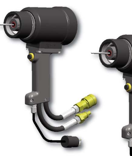
5 3585 Huck Model 3585 In line Hydraulic Installation Tool is designed to install 16 (1/2 ) to 24 (3/4 ) Pintail style Lockbolt Fasteners. This tool operates on 7400 psi (510 BAR) PULL and 2200 psi (151 BAR) RETURN pressures as supplied by Huck Hydraulic POWERIG Models 918 or equivalent. Lengths and weights do not include Nose Assemblies. Except for a nose assembly, the tool is complete with handle, hoses, couplers and control cord ready to be attached to a HUCK POWERIG. The 3585 tool is basically a cylinder and piston assembly. An unloading valve, designed to relieve the hydraulic pressure at both ends of the stroke, is positioned by the piston. A pintail ejector is provided to eject the broken pintail from the nose assembly. The end of the piston rod is threaded and a nose adapter and retaining rings are included for attaching nose assemblies. Proper PULL and RETURN pressures are important for the proper function of the Installation Tool and Nose Assemblies, and for the safety of the operator. A Gauge Set up T CE is available for checking these pressures. Instructions are furnished with the Gauge and in applicable POWERIG Instruction Manuals. DESCRIPTION 3585PT Huck Model 3585PT In line Hydraulic Installation Tool is designed to install all 16 (1/2 ) to 24 (3/4 ) Huck Spin, Huck Spin2, and BOBTAIL Fasteners. This tool operates on 7400 psi (510 BAR) PULL and 2200 psi (151 BAR) RETURN pressures as supplied by Huck Hydraulic POWERIG Models 918 or equivalent. Lengths and weights do not include Nose Assemblies. Except for a nose assembly, the tool is complete with handle, hoses, couplers and control cord ready to be attached to a HUCK POWERIG. The 3585PT tool is basically a cylinder and piston assembly. An unloading valve, designed to relieve the hydraulic pressure at both ends of the stroke, is positioned by the piston. The 3585PT does not have a pintail ejector as it is designed to install those fasteners without pintail break. The piston includes a pass through hole to allow the included T wrench to install Huck Spin collars.. Proper PULL and RETURN pressures are important for the proper function of the Installation Tool and Nose Assemblies, and for the safety of the operator. A Gauge Set up T CE is available for checking these pressures. Instructions are furnished with the Gauge and in applicable POWERIG Instruction Manuals. 5
6 SPECIFICATIONS POWER SOURCE: Huck POWERIG Hydraulic Unit HOSE KITS: Use only genuine HUCK Hose Kits 10,000 psi working pressure. HYDRAULIC FLUID: Hydraulic fluid shall meet DEXRON III, DEXRON VI, MERCON, Allison C 4 or equivalent ATF specifications. Fire resistant fluid may be used if it is an ester based fluid such as Quintolubric HFD or equivalent. Water based fluid shall NOT be used as serious damage to equipment will occur. WEIGHT: 19 lbs (8.62 kg) STROKE: inches (4.60 cm) 3585PT 1.90 inches (4.83 cm) MAX OPERATING TEMP: 125 F (51.7 C) MAX FLOW RATE: 2 gpm (7.5 l/m) MAX PULL PRESSURE: 7400 psi, (510 bar) MAX RETURN PRESSURE: 2200 psi, (151 bar) PULL CAPACITY: 45,668 lbs ( psi STICKERTICKER LOCATIONS The 3585 series tools come labeled with important stickers which contain safety and pressure settings information. It is necessary that these stickers remain on the tools and are easily read. If stickers become damaged or worn, or if they have been removed from the tool, they must be replaced. The part numbers are shown in the drawing below CE & WARNING Sticker (Maximum Operating Pressures) HUCK & Year of Mfr Sticker 6
7 PRINCIPLE OF OPERATION Pintail Ejector Piston Travel PULL Piston Piston Travel Trigger Switch Dump Valve Pressurized Oil Hydraulic Hoses Return Oil PULL PRESSURE RETURN PRESSURE PULL PRESSURE RETURN PRESSURE Pull Pressure (Pull Cycle) Fig. 1(a) Return Pressure (Return Cycle) Fig. 1(b) When the trigger is depressed, a solenoid operated valve in the POWERIG directs pressurized hydraulic fluid through the PULL hose to the front side of the piston, and allows fluid on the RETURN side to flow back to the tank (Fig 1a). The piston and nose assembly collet moves rearward installing the fastener. When the piston reaches the end of the PULL stroke, it uncovers flats on the rear end of the dump valve. These flats provide a passage for hydraulic fluid from the PULL side to the RETURN side of the piston, unloading or dumping the pressurized fluid back to the tank (Fig 1a). When the trigger is released the solenoid is deenergized and the valve directs pressurized fluid to the rear side of the piston and allows fluid on the PULL side to flow back to the tank (Fig. 1b). This causes piston and collet to move forward and pushes the nose assembly and tool off the swaged (installed) fastener. When the piston reaches the end of the return stroke, pressure is built up, causing the Powerig to shut off, completing the cycle. 7


8 PREPARATION FOR USE WARNINGS: Read full manual before using tool. A half-hour training session with qualified personnel is recommended before using Huck equipment. When operating Huck installation equipment, always wear approved eye and ear protection. Be sure there is adequate clearance for the operator s hands before proceeding. CAUTION: Do not let disconnected hoses and couplers contact a dirty floor. Keep harmful material out of hydraulic fluid. Dirt in hydraulic fluid causes valve failure In Tool and In POWERIG Hydraulic Unit. CAUTION: Do not use TEFLON tape on pipe threads. Pipe threads may cause tape to shred resulting in tool malfunction. Threadmate is available from Huck in a 4oz. tube as part number Huck recommends that only Huck Powerig Hydraulic Units be used as a power source for Huck installation equipment. Hydraulic power units that deliver high pressure for both PULL and RETURN, AND ARE NOT EQUIPPED WITH RELIEF VALVES ARE SPECIFICALLY NOT RECOMMENDED AND MAY BE DANGEROUS. POWER SOURCE CONNECTIONS Remove shipping caps from ends of pipe plug fittings. Coat pipe plug threads, hose fitting threads, and quick connect fittings with Threadmate, which is available from Huck in a 4oz. tube as part number Connect tool's control switch electrical cord to hydraulic unit. WARNING: Be sure to connect Tool s hydraulic hoses to POWERIG Hydraulic Unit before connecting Tool s switch control cord to unit. If not connected in this orderand disconnected in the reverse order, severe personal Injury may occur. 4. Connect hydraulic unit to power supply. Turn unit to ON. Hold tool trigger depressed for 30 seconds; depress trigger a few times to cycle tool and to circulate hydraulic fluid. Observe action of tool and check for leaks. Turn unit to OFF. 5. Select nose assembly for fastener to be installed. Disconnect tool's control switch electrical cord from hydraulic unit; disconnect unit from power supply. Attach nose assembly to tool. 6. Reconnect hydraulic unit to power supply. Reconnect tool's switch control cord to unit. Check operation of nose assembly; install fasteners in test plate of correct thickness with proper size holes. Inspect installed fasteners. If fasteners do not pass inspection, see TROUBLESHOOTING to locate and correct tool malfunction. WARNING: Correct PULL and RETURN pressures are required for operator s safety and for Installation TooI s function. Pressure Gauge T CE is available for checking pressures. See Tool SPECIFICATIONS and Gauge Instruction Manual. Failure to verify pressures may result in severe personal injury. 1. Use Huck POWERIG Hydraulic Unit, or equivalent, that has been prepared for operation per applicable instruction manual. Check both PULL and RETURN pressures, and if required, adjust to pressures given in SPECIFICATIONS. 2. First, turn hydraulic unit to OFF, and then, disconnect power supply from unit. Connect tool's hoses to Powerig unit. * Threadmate is a registered trademark of Parker Intangibles LLC * TEFLON is a registered trademark of DuPont Corp. 8

9 OPERATING INSTRUCTIONS WARNING: Reasonable care of installation tools by operators is an important factor in maintaining tool effeciency and in reducing repair downtime. Do not abuse the tool by dropping it, using it as a hammer, or otherwise, causing unnecessary wear and tear. Be sure there is adequate clearance for the tool and operator s hands before proceeding. Do not connect tool s hoses to each other or use hoses as a handle for carrying. WARNING: Do not pull on a fastener without a collar. If a fastener is pulled without a collar, the fastener will eject forcibly when the pintail breaks off. 4. Push nose assembly onto the fastener until the nose assembly anvil stops against the collar. Tool and nose assembly must be held at right angles (90 ) to the work. 5. Depress tool switch to start installation cycle. 6. When forward motion of nose assembly anvil stops and pintail breaks off, release switch. Tool will go into its return stroke, push off the installed fastener and eject the pintail. 7. The tool and nose assembly is ready for the next installation cycle. TO INSTALL A HUCKBOLT FASTENER 1. Check work and remove excessive gap in the space between sheets. Gap is excessive if not enough pintail sticks through the collar for the nose assembly jaws to grab onto. 2. Put fastener into hole. 3. Slide collar over fastener. (The beveled end of the collar must be towards the nose assembly and tool.) 9

10 CAUTIONS: - Consult MSDS before servicing tool. - Keep dirt and other material out of hydraulic system. - Separated parts most be kept away from dirty work surfaces. - Dirt/debris in hydraulic fluid causes Dump Valve failure in Tool and in POW- ERIG Hydraulic Unit s valves. - Always check tool assembly drawing for the proper direction of the flats on the Dump Valve. See SPECIFICATIONS for fluid type. Dispose of fluid in accordance with local environmental regulations. Recycle steel, aluminum, and plastic parts in accordance with local lawful and safe practices. PREVENTIVE MAINTENANCE NOTE: For supplementary information refer to TROUBLESHOOTING, Parts Lists, and DISASSEMBLY AND ASSEMBLY procedures in this manual. CAUTION: Do not use TEFLON tape on pipe threads. Pipe threads may cause tape to shred resulting in tool malfunction. Threadmate is available from Huck in a 4oz. tube as part number CAUTION: Always replace seals, wipers, and back-up rings when tool is disassembled for any reason. SYSTEM INSPECTION Operating efficiency of the installation tool is directly related to performance of the complete system, including the tool with nose assembly, hydraulic hoses, trigger and control cord, and POWERIG. SERVICING THE TOOL HYDRAULIC COUPLINGS Therefore, an effective preventive maintenance program includes scheduled inspections of the system to detect and correct minor troubles. 1. Inspect tool and nose for external damage. 2. Verify that hydraulic hose fittings and couplings and electrical connections are secure. 3. Inspect hydraulic hose for signs of damage or aging. Replace hoses if damaged..4. Inspect tool, hose, and POWERIG during operation to detect abnormal heating, leaks, or vibration. POWERIG MAINTENANCE Maintenance instructions and repair procedures are in the appropriate POWERIG Instruction Manual. TOOL MAINTENANCE At regular intervals, depending on use, replace all O- rings and back-up rings in the tool. Spare Parts Kit 3585KIT or 3585PTKIT should be kept on hand. Inspect cylinder bore, piston and piston rod and unloading valve for scored surfaces, excessive wear or damage, and replace as necessary. NOSE ASSEMBLY MAINTENANCE Daily cleaning of the nose assembly is recommended. This can usually he accomplished by dipping nose assembly in mineral spirits, or other suitable solvent, to clean jaws and wash away metal chips and dirt. If more thorough cleaning or maintenance is necessary, disassemble the nose assembly. Use a sharp pointed pick to remove imbedded particles from the pull grooves of the jaws. * Threadmate is a registered trademark of Parker Intangibles LLC * TEFLON is a registered trademark of DuPont Corp. 10
11 DISASSEMBLY AND ASSEMBLY PREPARATION GENERAL PRECAUTIONS During disassembly and assembly, take the following precautions to avoid damaging tool or components: (a) Always work on a clean surface. (b) Use relatively soft materials, such as brass, aluminum or wood, to protect tool when applying pressurepplying pressure. (c) Apply a continuous strong pressure, rather than sharp blows, to disassemble or assemble a component. An arbor press provides steady pressure to press a component in or out. (d) Never continue to force a component if it hangs up due to misalignment. Reverse the procedure to correct misalignment and start over. (e) Smear Lubriplate TM 13OAA or equivalent on O- rings and mating surfaces to aid assembly and prevent damage to O-rings. (A handy tube of Lubriplate 13OAA is available from Huck as part number ). (f) WARNING: Be sure to disconnect Tool s electrical control trigger system from POWERIG Hydraulic Unit BEFORE disconnecting Tool s hydraulic hoses from unit. If not disconnected in this order before any maintenance or cleaning is done, severe personal injury may occur. Coat pipe plug threads, hose fitting threads, and quick connect fittings with Threadmate, which is available from Huck in a 4oz. tube as part number DO NOT use Teflon tape on hose fitting threads. DISASSEMBLY AND ASSEMBLY TOOLS Standard hand tools such as wrenches, drifts, copper or lead hammers, screwdrivers, socket screw hexagon keys, long forceps (tweezers), etc. which can be purchased at most local supply firms are required. If possible, an arbor press and vise with soft jaws should be available. Wrench is available for Ejector Gland. Wrench is available for End Cap. SPARE PARTS AND SPARE PARTS KITS The quantity of spare parts that should be kept on hand varies with the application and number of tools in service. However, spare parts kits containing perishable parts such as O-rings, back-up rings, etc., should be kept on hand at all times. POWERIG MAINTENANCE Maintenance instructions and repair procedures are in the appropriate POWERIG Instruction Manual. TOOL MAINTENANCE At regular intervals, depending on use, replace all O- rings and back-up rings in the tool. Spare Parts Kit 3585KIT or 3585PTKITshould be kept on hand. Inspect cylinder bore, piston and piston rod and unloading valve for scored surfaces, excessive wear or damage, and replace as necessary. NOSE ASSEMBLY MAINTENANCE Daily cleaning of the nose assembly is recommended. This can usually he accomplished by dipping nose assembly in mineral spirits, or other suitable solvent, to clean jaws and wash away metal chips and dirt. If more thorough cleaning or maintenance is necessary, disassemble the nose assembly. Use a sharp pointed pick to remove imbedded particles from the pull grooves of the jaws. * Threadmate is a registered trademark of Parker Intangibles LLC * TEFLON is a registered trademark of DuPont Corp. * LUBRIPLATE is a registered trademark of Fiske Brothers Refining Co. 11
12 DISASSEMBLY WARNING: Be sure to disconnect Tool s electrical control trigger system from POWERIG Hydraulic Unit BEFORE disconnecting Tool s hydraulic hoses from unit. If not disconnected in this order before any maintenance or cleaning is done, severe personal injury may occur. DISASSEMBLY The following procedure is for complete disassembly. Disassemble only components necessary to check damaged O-ring, C-ring, back-up ring, or other components. 1. Uncouple tool hydraulic hoses, and disconnect electrical control cord. 2. Remove Sleeve (19) and Split Ring (20). Remove nose assembly. 3. Remove Coupler Nipple (32) and Coupler Body (33). Drain Hydraulic Hoses (12) into a clean container. 4. Push rearward on Piston (29) until hydraulic fluid is drained into container : Remove Retaining Ring (5) and Cover Plate (4). 3585PT: Remove Screws (5) and Retainer (6) : Use Wrench to remove End Cap (6). 3585PT: Use Wrench to remove End Cap Assembly (21). 8. Pull piston out of adapter, and remove Unloading Valve (8) from piston. NOTE: The ejector gland can be removed to inspect and/or replace components without completely disassembling tool. 9. Remove Ejector Gland Assembly (21) and Pintail Ejector (22) from piston. Use Special Wrench, P/N , to unscrew gland. 10. Use a small diameter, dull-pointed rod to remove O-rings, and back-up rings from all components. 11. Remove Socket Head Cap Screw (10) from Handle Assembly (9). 12. Remove two Button Head Cap Screws from onehalf of handle and cylinder. 13. Separate handle halves, and lift out assemble Switch (16), Control Cord (14) including Cord Connector (13), and Strain Relief (15). 14. Remove remaining button head cap screws and handle half. Remove both Hydraulic Hoses (12) from cylinder. 15. Loosen two screws at rear of switch to remove switch from electrical cord. Remove two #6-32 socket set screws to disassemble switch for cleaning. Pull strain relief grommet from cord. 16. Disassemble electrical connector to replace Connector, or to rewire. 7. Push rearward on Adapter Assembly (23) and piston, along with adapter, will slide from cylinder. 12

13 ASSEMBLY All Models Numbers in parentheses ( ) are reference numbers for: 3585 shown in Figure 8; 3585PT in Figure 9. WARNING: Do not omit any seals during servicing, leaks will result and personal injury may occur. WARNING: Tool must be fully assembled with all components included. CAUTION: Do not use TEFLON tape. Before assembling tool: (a) Clean components In mineral spirits or other solvent compatible With O-ring seals. (b) Clean out O-ring grooves. ASSEMBLY 6. Assemble ejector gland assembly and pintail ejector to the piston as Press follows: Piston, Front Gland, and a. Insert Pintail Ejector Piston (22) Assembly into Piston Tool (29). b. Drop in Ejector GLYD Washer Ring (21e). Insertion Tool (2624 & 2624HS) c (2628) Drop in O-ring (21d). (2630) d. Screw in Gland (21a) with O-ring (21g) in groove in threads, back-up ring (21b) and QUAD ring (21c) inside and Ejector Rod Wiper (21f) in place. e. Tighten Ejector Gland Assembly with Wrench. 7. Push Nose Adapter (23) into Cylinder. 8. Install Retaining Ring (18) into groove in adapter. (c) Inspect components for scoring, excessive wear or damage. (d) Replace O-rings and back-up rings. Be sure that relative positions of the O-rings and back-up rings are as shown in Figure 8. (e) Service Kit part number 3585KIT contains O- Note Rings, POLYSEAL Back-up Rings and other seals necessary for servicing Direction this tool. (f) Smear Lubriplate 130AA on O-rings and mating surfaces to prevent damage to O-rings and to aid assembly FRONT GLAND 13 ASSEMBLY 4 1. Assemble electrical Control Cord (14) to plug of electrical Connector (13). 2624HS Piston 2. Push cord thru Strain Relief (15), and attach to Switch (16). PISTON ASSEMBLY TOOL (2624, 2624HS, 2628) 3. Screw both (2630) Hoses (12) into Cylinder (1). 4. Loosely attach handle half by turning two Button Head Cap Screws into cylinder. 9. Push assembled Piston (23), assembled Front Gland with all O-rings, back-up rings, Polyseals, Wiper (24) and Wiper Housing (25) in place, and into assembled cylinder and adapter. 10. Slide Unloading Valve (22) into hole thru piston. BE SURE UNLOADING VALVE IS ASSEMBLED WITH FOUR FLATS TO THE REAR AS SHOWN. 11. Tighten End Cap, then, back off until Locator can be placed in closest matching grooves : After End Cap is locked in place, install Cover Plate (4) and Retaining Ring (5). 3585PT: After End Cap is locked in place, install Retainer (6) and Cap Screws (5). 13. Screw Coupler Nipple (32) onto hose in port P and Coupler Body (33) onto hose in port R. 14. Connect tool hoses to POWERIG hoses and cycle tool a few times. Observe action of tool and check for leaks. 15. Attach nose assembly to tool following applicable Nose Assembly Data Sheet. Use Split Ring Set and Retaining Sleeve furnished with tool. 5. Place assembled switch, electrical cord, strain relief and electrical connector into handle recesses. Evenly tighten four cap screws to 50 in. lbs. torque if plated, and 70 in. lbs. if unplated, while holding assembled components in position. 13
14 3585 ASSEMBLYA DRAWING Figure f 21g a 21b 21c 21d 21e 21 - Ejector Gland Assembly Detail Item Description Part No. Qty. 1 Cylinder O-Ring Back-up Ring Cover Plate Retaining Ring End Cap Locking Disk Dump Valve Handle #6 Screw #10 Screw Hose Cord Connector Control Cord Strain Relief Trigger Switch Assy Set Screw Retaining Ring Sleeve Split Ring Ejector Gland Assy a Gland b Back-up Ring c QUAD Ring d O-Ring e Ejector Washer f Ejector Rod Wiper g O-Ring Item Description Part No. Qty. 22 Pintail Ejector Nose Adapter Wiper Seal Wiper Housing Front Gland Polyseal GLYD Ring Piston HUCK Sticker Caution Sticker Male Connector Female Connector
15 3585PT ASSEMBLYA DRAWING d 2c 2a 2b 3b 3a 23, 24 4c 4d 4a 5 22 Figure f 2e 7 8, 9 14, 15 4g 4b 4e 4f 21 10, Item Description Part No Qty 1 Cylinder Gland Assy a Front Gland b Polyseal c Wiper Housing d Wiper e O-Ring f Back-up Ring Piston Assy a Piston b GLYD Ring End Cap Assy a End Cap b Spacer Item Description Part No Qty 4c O-Ring d Back-up Ring e Polyseal f Wiper Seal g Retaining Ring Retainer Locking Disk Dump Valve Handle Socket Hd Screw Hose Cord Connector Control Cord Strain Relief Item Description Part No Qty 14 Trigger/O-Ring Assy Setscrew Retainaing Ring Sleeve Split Ring Nose Adapter Male Connector Female Connector Screw HUCK Sticker Caution Sticker Cable Ties
16 TROUBLESHOOTING Always check the simplest possible cause of a malfunction first (example: a loose or disconnected trigger line). Then proceed logically and eliminate each possible cause until the defect is found. Where possible, substitute known good parts for suspected defective parts. Use the following steps as an aid in troubleshooting. 1. Tool fails to operate when trigger is pressed. a. Inoperative POWERIG Hydraulic Unit. See applicable instruction manual. b. Loose electrical connections. c. Damaged trigger assembly. d. Loose or faulty hose coupling. 2. Tool operates in reverse. a. Reversed hose connections between hydraulic unit and tool. 3. Tool leaks hydraulic fluid. a. Defective tool O-rings or loose connections at tool. 4. Hydraulic couplers leak fluid. a. Damaged or worn O-rings in Coupler Body Coupler 5. Hydraulic fluid overheats. a. Unit not operating properly. See units manual. b. Unit running in reverse (918; only). See unit s manual. 7. Pull grooves on fastener pintail stripped during PULL stroke. a. Operator not sliding anvil completely onto fastener pintail. b. Incorrect fastener grip. c. Worn or damaged jaw segments. d. Metal particles in jaw grooves. e. Excessive sheet gap. 8. Collar of fastener not completely swaged. a. Improper tool operation. See No. 6. b. Scored anvil. 9. Tool "hangs up" on swaged collar of fastener. a. Improper tool operation. See No. 6. b. RETURN pressure too low. c. Not enough collar lubricant. d. Nose assembly not installed correctly. 10. Pintail of fastener fails to break. a. Improper tool operation. See No. 6. b. Pull grooves on fastener stripped. See No. 7. c. PULL pressure too low. 11. Nose will not release broken pintail. a. Nose assembly not installed correctly. b. Bent or broken Pintail Ejector. 6. Tool operates erratically and fails to install fastener properly. a. Low or erratic hydraulic pressure. Air in system. b. Damaged or worn Piston O-ring in tool. c. Excessive wear on sliding surfaces of tool parts. SERVICE KIT: 3585KIT or 3585PTKIT ACCESSORIES: Ejector Gland Wrench End Cap Hex Wrench Remote Trigger (All Models) KITS AND ACCESSORIES 16
17 TOOLING WARRANTY: Huck warrants that tooling and other items (excluding fasteners, and hereinafter referred as "other items") manufactured by Huck shall be free from defects in workmanship and materials for a period of ninety (90) days from the date of original purchase. WARRANTY ON "NON STANDARD OR CUSTOM MANUFACTURED PRODUCTS": With regard to non-standard products or custom manufactured products to customer's specifications, Huck warrants for a period of ninety (90) days from the date of purchase that such products shall meet Buyer's specifications, be free of defects in workmanship and materials. Such warranty shall not be effective with respect to non-standard or custom products manufactured using buyer-supplied molds, material, tooling and fixtures that are not in good condition or repair and suitable for their intended purpose. THERE ARE NO WARRANTIES WHICH EXTEND BEYOND THE DESCRIPTION ON THE FACE HEREOF. HUCK MAKES NO OTHER WAR- RANTIES AND EXPRESSLY DISCLAIMS ANY OTHER WARRANTIES, INCLUDING IMPLIED WARRANTIES AS TO MERCHANTABILITY OR AS TO THE FITNESS OF THE TOOLING, OTHER ITEMS, NONSTANDARD OR CUSTOM MANUFAC- TURED PRODUCTS FOR ANY PARTICULAR PUR- POSE AND HUCK SHALL NOT BE LIABLE FOR ANY LOSS OR DAMAGE, DIRECTLY OR INDI- RECTLY, ARISING FROM THE USE OF SUCH TOOLING, OTHER ITEMS, NONSTANDARD OR CUSTOM MANUFACTURED PRODUCTS OR BREACH OF WARRANTY OR FOR ANY CLAIM FOR INCIDENTAL OR CONSEQUENTIAL DAM- AGES. Huck's sole liability and Buyer's exclusive remedy for any breach of warranty shall be limited, at Huck's option, to replacement or repair, at FOB Huck's plant, of Huck manufactured tooling, other items, nonstandard or custom products found to be defective in specifications, workmanship and materials not otherwise the direct or indirect cause of Buyer supplied molds, material, tooling or fixtures. Buyer shall give Huck written notice of claims for defects within the ninety (90) day warranty period for tooling, other items, nonstandard or custom products described above and Huck shall inspect products for which such claim is made. TOOLING, PART(S) AND OTHER ITEMS NOT MANU- FACTURED BY HUCK: HUCK MAKES NO WARRANTY WITH RESPECT TO THE TOOLING, PART(S) OR OTHER ITEMS LIMITED WARRANTIES 17 MANUFACTURED BY THIRD PARTIES. HUCK EXPRESSLY DISCLAIMS ANY WARRANTY EXPRESSED OR IMPLIED, AS TO THE CONDI- TION, DESIGN, OPERATION, MERCHANTABILITY OR FITNESS FOR USE OF ANY TOOL, PART(S), OR OTHER ITEMS THEREOF NOT MANUFAC- TURED BY HUCK. HUCK SHALL NOT BE LIABLE FOR ANY LOSS OR DAMAGE, DIRECTLY OR INDI- RECTLY, ARISING FROM THE USE OF SUCH TOOLING, PART(S) OR OTHER ITEMS OR BREACH OF WARRANTY OR FOR ANY CLAIM FOR INCIDENTAL OR CONSEQUENTIAL DAM- AGES. The only warranties made with respect to such tool, part(s) or other items thereof are those made by the manufacturer thereof and Huck agrees to cooperate with Buyer in enforcing such warranties when such action is necessary. Huck shall not be liable for any loss or damage resulting from delays or nonfulfillment of orders owing to strikes, fires, accidents, transportation companies or for any reason or reasons beyond the control of the Huck or its suppliers. HUCK INSTALLATION EQUIPMENT: Huck International, Inc. reserves the right to make changes in specifications and design and to discontinue models without notice. Huck Installation Equipment should be serviced by trained service technicians only. Always give the Serial Number of the equipment when corresponding or ordering service parts. Complete repair facilities are maintained by Huck International, Inc. Please contact one of the offices listed below. Eastern One Corporate Drive Kingston, New York Telephone (845) FAX (845) Outside USA and Canada Contact your nearest Huck International Office, see back cover. In addition to the above repair facilities, there are Authorized Tool Service Centers (ATSC's) located throughout the United States. These service centers offer repair services, spare parts, Service Parts Kits, Service Tools Kits and Nose Assemblies. Please contact your Huck Representative or the nearest Huck office listed on the back cover for the ATSC in your area.

18 One Great Connection SM A Global Organization Alcoa Fastening Systems (AFS) maintains company offices throughout the United States and Canada, with subsidiary offices in many other countries. Authorized AFS distributors are also located in many of the world s Industrial and Aerospace centers, where they provide a ready source of AFS fasteners, installation tools, tool parts, and application assistance. Alcoa Fastening Systems world-wide locations: Americas Far East Europe Alcoa Fastening Systems Aerospace Products Tucson Operations 3724 East Columbia Tucson, AZ FAX: Alcoa Fastening Systems Aerospace Products Carson Operations PO Box Watson Center Rd. Carson, CA FAX: Alcoa Fastening Systems Industrial Products Kingston Operations 1 Corporate Drive Kingston, NY FAX: Alcoa Fastening Systems Industrial Products Latin America Operations Avenida Parque Lira Tacubaya Mexico, D.F. C.P FAX: TELEX: LUKSME Alcoa Fastening Systems Industrial Products Australia Operations 14 Viewtech Place Rowville, Victoria Australia Toll Free: FAX: Alcoa Fastening Systems Industrial Products United Kingdom Operations Unit C, Stafford Park 7 Telford, Shropshire England TF3 3BQ FAX: Alcoa Fastening Systems Aerospace Products France Operations Clos D Asseville BP Us Par Vigny France FAX: Alcoa Fastening Systems Industrial Products Waco Operations PO Box Imperial Drive Waco, TX FAX: Certified to ISO 9001:2008 Industrial Products Industrial Products Certified to ISO 14001:2004 For The Long Haul, The Future of Fastening Technology, The Future of Assembly Technology, The Future of Tooling Technology, and Tools of Productivity are service marks of Huck International. Huck provides technical assistance regarding the use and application of Huck fasteners and tooling. NOTICE: The information contained in this publication is only for general guidance with regard to properties of the products shown and/or the means for selecting such products, and is not intended to create any warranty, express, implied, or statutory; all warranties are contained only in Huck s written quotations, acknowledgements, and/or purchase orders. It is recommended that the user secure specific, up to date data and information regarding each application and/or use of such products. HWB M For the Long Haul 2003 Alcoa Fastening Systems 1 Corporate Drive, Kingston, NY Tel: Fax:
INSTRUCTION MANUAL HYDRAULIC INSTALLATION TOOLS
 INSTRUCTION MANUAL HYDRAULIC INSTALLATION TOOLS 2624 2628 P R 2630 2624HS 04-01-2004 HK1052 2 CONTENTS EU DECLARATION OF CONFORMITY.............................2 CONTENTS.................................................3
HUCK FASTENERS HUCK FASTENERS HUCK FASTENERS HUCK FASTENERS HUCK FASTENERS HUCK FASTENERS HUCK FASTENERS HUCK FASTENERS INSTRUCTION MANUAL
 INSTRUCTION MANUAL 230 PNEUDRAULIC INSTALLATION TOOL HUCK FASTENERS HUCK FASTENERS HUCK FASTENERS HUCK FASTENERS HUCK FASTENERS HUCK FASTENERS HUCK FASTENERS HUCK FASTENERS U.S. Patent 4,878,372; 4,964,292
INSTRUCTION MANUAL HS24LH HYDRAULIC INSTALLATION TOOL
 INSTRUCTION MANUAL HS24LH HYDRAULIC INSTALLATION TOOL Form HK 1024 04-22-2004 EU Declaration of Conformity Manufacturer: Huck International, Inc., Installation Systems Division, 1 Corporate Drive, Kingston,
Instruction Manual HPT25RH, HPT35RH, and HPT57RH Hydraulic Installation Tools
 Instruction Manual HPT25RH, HPT35RH, and HPT57RH Hydraulic Installation Tools November 4, 2016 HK827 Makers of Huck, Marson, Recoil Brand Fasteners, Tools & Accessories 2 Contents EC Declaration of Conformity...2
Instruction Manual. hydraulic installation tools. April 28, 2015 HK1180. Makers of Huck, Marson, Recoil Brand Fasteners, Tools & Accessories
 Instruction Manual BobTail Installation System SF32 & SF32L hydraulic installation tools Makers of Huck, Marson, Recoil Brand Fasteners, Tools & Accessories April 28, 2015 HK1180 2 Contents Safety.................................
INSTRUCTION MANUAL HYDRAULIC INSTALLATION TOOLS
 INSTRUCTION MANUAL HYDRAULIC INSTALLATION TOOLS HUCK SPINC UTTER COLLAR CUTTING KITS 03-04-2005 HK1055 2 CONTENTS SAFETY...................................................4 SPECIFICATIONS.............................................5
A1100 Pneumatic Installation Tool
 Instruction Manual A1100 Pneumatic Installation Tool Safety Instructions 3 Description Specifications Principle of Operation Preparation for Use Operating Instructions 5 Attaching a Nose Assembly 5 Maintenance
SFBTT8 series. Instruction Manual. BobTail Hydraulic Installation Tools. Declaration of Conformity 2. Safety Instructions 3-4. Sticker Locations 4
 Instruction Manual SFBTT8 series BobTail Hydraulic Installation Tools Declaration of Conformity 2 Safety Instructions 3-4 Sticker Locations 4 Specifications 5 Principle of Operation 5 Preparation for Use
968 and 968D Powerig Hydraulic Units
 Instruction Manual 968 and 968D Powerig Hydraulic Units Declaration of Conformity 2 Safety Instructions 3-4 Principle of Operation 5 Description 5 968 Specifications 6 Optional Equipment 6 Additional Safety
Instruction Manual EPS6V and EPS6VL. Ebbert Collection Unit. Safety Instructions 3. Description 4. Specifications 4. Principle of Operation 5
 Instruction Manual EPS6V and EPS6VL Ebbert Collection Unit Safety Instructions 3 Description 4 Specifications 4 Principle of Operation 5 Maintenance 5 General Components Drawings and Parts Lists 6-8 Vacuum
7142 & Instruction Manual. Hydraulic Installation Tool Safety Instructions 3-4. Description 5.
 Safety Instructions 3-4 Instruction Manual 7142 & 8142 Hydraulic Installation Tool Description 5 Specifications 5 Principle of Operation 5 Preparation for Use 6 7142 7142-20 Operating Instructions 7 Maintenance
Instruction Manual. Hydraulic Installation Tool. Declaration of Conformity 2. Safety Instructions 3-4. Description 5. Specifications 5-7
 Instruction Manual 2580 Hydraulic Installation Tool Declaration of Conformity 2 Safety Instructions 3-4 Description 5 Specifications 5-7 Principle of Operation 8 Preparation for Use 8 Operating Instructions
Instruction Manual. Hydraulic Installation Tool. Declaration of Conformity 2. Safety Instructions 3-4. Description 5.
 Declaration of Conformity 2 Instruction Manual 507 Hydraulic Installation Tool Safety Instructions 3-4 Description 5 Specifications 5 Principle of Operation 6 Preparation for Use 7 Operating Instructions
Instruction Manual SF60 BobTail Hydraulic Installation Tool
 Declaration of Conformity 2 Instruction Manual SF60 BobTail Hydraulic Installation Tool Safety Instructions 3-4 Tool Specifications 5 Optional Equipment 5 Principle of Operation 6 Preparation for Use 6
INSTRUCTION MANUAL 940HS & HS POWERIG HYDRAULIC UNIT Form HK943
 INSTRUCTION MANUAL 940HS & 940-0HS POWERIG HYDRAULIC UNIT 05-5-004 Form HK943 SAFETY This instruction manual must be read with particular attention to the following safety guide lines, by any person servicing
INSTRUCTION MANUAL MODEL 5901 HYDRAULIC INSTALLATION TOOL
 INSTRUCTION MANUAL MODEL 5901 HYDRAULIC INSTALLATION TOOL Form HK 499 03-18-2004 EU Declaration of Conformity Manufacturer: Huck International Inc., Installation Systems Division, 85 Grand Street, Kingston,
MODEL 2600 AND
 INSTRUCTION MANUAL MODEL 2600 AND 2600-16 HYDRAULIC INSTALLATION TOOL Form HK 914 03-11-2004 EU Declaration of Conformity Manufacturer: Huck International Inc., Installation Systems Division, 85 Grand
940S-2 and 940S-2-230
 Safety Instructions 3 Instruction Manual 940S-2 and 940S-2-230 Powerig Hydraulic Units Specifications 4-5 Electrical Schematics 6 Description 7 Principle of Operation 7 Preparation for Use 8 Checking and
B1100 series. Instruction Manual. Battery-Powered Tool. EC Declaration of Conformity 2. Safety Instructions 3-4, 8. Description 5
 EC Declaration of Conformity 2 Instruction Manual B1100 series Battery-Powered Tool Safety Instructions 3-4, 8 Description 5 Principle of Operation 5 Specifications and Battery and Charger Safety 5-6 Maintenance
5304, 6304, 7304, 8304, 9304 series
 Instruction Manual 504, 604, 704, 804, 904 series Hydraulic Installation Tools serial numbers 0401 and above Declaration of Conformity Safety Instructions -4 Description 5 Specifications 5 Principle of
516, 520, 524, 528, 532, 536
 Safety Instructions 3-4 Instruction Manual 516, 520, 524, 528, 532, 536 Hydraulic Collar Cutter Models Description 5 Specifications 5 Sticker Locations 5 Principle of Operation 6 Preparation for Use 6
INSTRUCTION MANUAL PNEUDRAULIC INSTALLATION TOOL. Form HK
 INSTRUCTION MANUAL 246 PNEUDRAULIC INSTALLATION TOOL HUCK U.S. PAT. 4597263 246 Form HK 825 02-10-2004 EU Declaration of Conformity Manufacturer: Huck International, Inc., Installation Systems Division,
EPS4 series. Instruction Manual. Ebbert Power Source. Safety Instructions 3. Description 4. Specifications 4. Principle of Operation 5.
 590441 REV B Instruction Manual EPS4 series Ebbert Power Source Safety Instructions 3 Description 4 Specifications 4 Principle of Operation 5 EPS4 Maintenance 5 EBBERT ENGINEERING TM Parts List 6 MADE
INSTRUCTION MANUAL PNEUDRAULIC INSTALLATION TOOL HK824
 INSTRUCTION MANUAL 245 PNEUDRAULIC INSTALLATION TOOL HUCK U.S. PAT. 4597263 245 03-10-2006 HK824 EU Declaration of Conformity Manufacturer: Huck International, Inc., Installation Systems Division, 1 Corporate
GB7624 GAGE BILT MADE IN U.S.A. HYDRAULIC INSTALLATION TOOL
 GB7624 HYDRAULIC INSTALLATION TOOL PLEASE CONTACT GAGE BILT FOR ALL OTHER SERIAL NUMBERS. GAGE BILT TOOLS ARE AVAILABLE WORLDWIDE E-MAIL US FOR DISTRIBUTOR NEAR YOU. GAGE BILT MADE IN U.S.A. GAGE BILT
BobTail Hydraulic Installation Tool Models
 Instruction Manual BobTail Hydraulic Installation Tool Models BTT25-DT BT60-325-RA BTT57-DT BTT35-DT BTT25RH-DT BTT57R-DT EU Declaration of Conformity 2 Safety Instructions 3-4 Description 5 Principle
INSTRUCTION MANUAL 585 ALL MODELS HYDRAULIC INSTALLATION TOOL
 INSTRUCTION MANUAL 585 ALL MODELS HYDRAULIC INSTALLATION TOOL Form HK 602 03-15-2004 EU Declaration of Conformity Manufacturer: Huck International Inc., Installation Systems Division, 85 Grand Street,
Instruction Manual 3585 series Hydraulic Installation Tools
 Declaration of Conformity 2 Safety Instructions 3-4 Instruction Manual 3585 series Hydraulic Installation Tools Tool Description 5 Specifications 5 Principle of Operation 6 3585 Preparation for Use 7 3585PT
ERT1S ERT2S ERT3S ERT4S
 Safety Instructions 3-4 General Information 5 Instruction Manual ERTS ERT2S ERT3S ERT4S Ebbert Engineering Riveting Tools Principle of Operation 5 Specifications 6-7 Disassembly and Assembly Instructions
2024 series Pneudraulic Installation Tool
 Declaration of Conformity 2 Safety Instructions 3 Instruction Manual 2024 series Pneudraulic Installation Tool Patent Pending Specifications 4-6 Principle of Operation 7 Preparation for Use 7 Operating
EBBERT RIVETING SOLUTIONS SALES & ENGINEERING GUIDE
 EBBERT RIVETING SOLUTIONS SALES & ENGINEERING GUIDE 06-05-015 HK1060 CONTENTS CONTENTS... TOOLS ERT1S... & 4 ERTS...5 & 6 ERTS...7 & 8 ERT4S...9 & 10 ERT5S...11 & 1 ERT6S...1 & 14 ERTSMQ...15 & 16 ERT9
INSTRUCTION MANUAL 244BT PNEUDRAULIC INSTALLATION TOOL HK1113
 INSTRUCTION MANUAL 244BT PNEUDRAULIC INSTALLATION TOOL 10-09-2009 HK1113 EC Declaration of Conformity Manufacturer:, Industrial Products Group, 1 Corporate Drive, Kingston, NY, 12401, USA Description of
940S-2-HDC. Instruction Manual. Powerig Hydraulic Unit. Safety Instructions 3. Description 4. Specifications 4. Principle of Operation 5
 Safety Instructions Description 4 Instruction Manual 940S--HDC Powerig Hydraulic Unit Specifications 4 Principle of Operation 5 Electrical Schematics 5 Primary Components Drawing 6 Preparation for Use
GB2620 GAGE BILT MADE IN U.S.A. INSTALLATION TOOL
 GB2620 INSTALLATION TOOL GAGE BILT TOOLS ARE AVAILABLE WORLDWIDE E-MAIL US FOR DISTRIBUTOR NEAR YOU. GAGE BILT MADE IN U.S.A. GAGE BILT Inc. 44766 Centre Court (586) 226-1500 Clinton Twp. MI 48038 (586)
Instruction Manual 940S 940S S-380. Powerig Hydraulic Units. Safety Instructions 3. Description 4. Specifications 4. Principle of Operation 4
 Safety Instructions 3 Description 4 Instruction Manual 940S 940S-30 940S-380 Powerig Hydraulic Units Specifications 4 Principle of Operation 4 Preparation for Use 4 Checking and Adjusting Pressures 5 Operating
GB2620 GAGE BILT MADE IN U.S.A. INSTALLATION TOOL
 GB2620 INSTALLATION TOOL GAGE BILT TOOLS ARE AVAILABLE WORLDWIDE E-MAIL US FOR DISTRIBUTOR NEAR YOU. GAGE BILT MADE IN U.S.A. GAGE BILT Inc. 44766 Centre Court (586) 226-1500 Clinton Twp. MI 48038 (586)
2015 SERIES PNEUDRAULIC INSTALLATION TOOLS
 Distributed by Toll Free 1 800 563 1293 INSTRUCTION MANUAL 2015 SERIES PNEUDRAULIC INSTALLATION TOOLS ALL MODELS 03-07-2013 HK958 2 CONTENTS EU DECLARATION OF CONFORMITY.................................2
Instruction Manual T CE. Pressure Gauge. EC Declaration of Conformity 2. Safety Instructions 3-4. Description 5.
 Instruction Manual T-124833CE Pressure Gauge EC Declaration of Conformity 2 Safety Instructions 3-4 Description 5 Specifications 5 Principle of Operation 5 Maintenance 6 Checking Powerig Hydraulic Power
INSTRUCTION MANUAL MODEL 2480 (FOR BRAZIL) HYDRAULIC INSTALLATION TOOL
 HYDRAULIC INSTALLATION TOOL") INSTRUCTION MANUAL MODEL 2480 (FOR BRAZIL) HYDRAULIC INSTALLATION TOOL Form HK1065 04-29-2004 EU Declaration of Conformity Manufacturer: Alcoa Fastening Systems, 1 Corporate Drive, Kingston, NY, 12401,
INSTRUCTION MANUAL MODEL 2480 (FOR BRAZIL) HYDRAULIC INSTALLATION TOOL Form HK1065 04-29-2004 EU Declaration of Conformity Manufacturer: Alcoa Fastening Systems, 1 Corporate Drive, Kingston, NY, 12401,
INSTRUCTION MANUAL MODEL , A and A HYDRAULIC INSTALLATION TOOL
 INSTRUCTION MANUAL MODEL 208-625, A208-625 and A208-625-2 HYDRAULIC INSTALLATION TOOL Form HK 800 03-01-2004 EU Declaration of Conformity Manufacturer: Alcoa Fastening Systems, 1 Corporate Drive, Kingston,
INSTRUCTION MANUAL MODEL 2480 SERIES HYDRAULIC INSTALLATION TOOL
 INSTRUCTION MANUAL MODEL 2480 SERIES HYDRAULIC INSTALLATION TOOL Form HK 970 02-18-2004 EU Declaration of Conformity Manufacturer: Alcoa Fastening Systems, 1 Corporate Drive, Kingston, NY, 12401, USA Description
Instruction Manual 206 series Hydraulic Installation Tool
 Declaration of Conformity 2 Safety Instructions 3-4 Instruction Manual 206 series Hydraulic Installation Tool Tool Description 5 Principle of Operation 5 Tool Specifications 6 Operation/Installation Sequence
GB2581 GAGE BILT MADE IN U.S.A. INSTALLATION TOOL
 GB2581 INSTALLATION TOOL GAGE BILT TOOLS ARE AVAILABLE WORLDWIDE E-MAIL US FOR DISTRIBUTOR NEAR YOU. GAGE BILT MADE IN U.S.A. GAGE BILT Inc. 44766 Centre Court (586) 226-1500 Clinton Twp. MI 48038 (586)
ORIGINAL INSTRUCTIONS GB2628/GB2628A INSTALLATION TOOL
 ORIGINAL INSTRUCTIONS GB2628/GB2628A INSTALLATION TOOL GAGE BILT TOOLS ARE AVAILABLE WORLDWIDE E-MAIL US FOR A DISTRIBUTOR NEAR YOU. GAGE BILT MADE in USA 44766 Centre Court Clinton Twp. MI 48038 USA Ph:
INSTRUCTION MANUAL 212 PNEUDRAULIC INSTALLATION TOOL
 INSTRUCTION MANUAL 212 PNEUDRAULIC INSTALLATION TOOL 11-09-2009 HK838 THREADLOCKER RECOMMENDATION Loctite 243 THREADLOCKER TO REPLACE Vibra-Tite IN HUCK PNEUDRAULIC INSTALLATION TOOLS In order to ensure
Instruction Manual SF20 BobTail Hydraulic Installation Tool
 Declaration of Conformity 2 Safety Instructions 3-4 Tool Specifications 5 Instruction Manual SF20 BobTail Hydraulic Installation Tool Optional Equipment 5 Principle of Operation 6 Preparation for Use 6
PULSE TOOLS INSTRUCTION MANUAL & MAINTENANCE
 PULSE TOOLS INSTRUCTION MANUAL & MAINTENANCE R Rev 4.0 (11/21/2012) READ ALL THE INSTRUCTIONS COMPLETELY BEFORE OPERATION. COMPLY WITH ALL THE INSTRUCTIONS AND RULES IN THIS MANUAL AND SAVE THIS MANUAL
Instruction Manual 2502 & A2502 SERIES HYDRAULIC INSTALLATION TOOL Form HK 837
 Instruction Manual 2502 & A2502 SERIES HYDRAULIC INSTALLATION TOOL 03-10-2004 Form HK 837 EU Declaration of Conformity Manufacturer: Huck International Inc., Installation Systems Division, 85 Grand Street,
INSTRUCTION MANUAL 2013 AND
 INSTRUCTION MANUAL 2013 AND 2014 ALL MODELS PNEUDRAULIC INSTALLATION TOOL 01-23-2006 HK978 EU Declaration of Conformity Manufacturer: Huck International Inc., Installation Systems Division, 85 Grand Street,
Instruction Manual 2025 series Pneudraulic Installation Tools
 Declaration of Conformity 2 Safety Instructions 3 Instruction Manual 2025 series Pneudraulic Installation Tools Patent Pending Specifications 4-6 Principle of Operation 7 Preparation for Use 7 Operating
Instruction Manual 256 Pneudraulic Installation Tool
 Declaration of Conformity 2 Instruction Manual 256 Pneudraulic Installation Tool Patent Pending Safety Instructions 3 Principle of Operation 4 Tool Specifications 4 Preparation for Use 5 Maintenance 5
LUBRICATOR GUN INSTRUCTIONS-PARTS LIST. 10,000 psi (700 bar) Maximum Delivery Pressure. Detachable-type
 Maximum Delivery Pressure. Detachable-type") INSTRUCTIONS-PARTS LIST 306 460 INSTRUCTIONS This manual contains important warnings and information. READ AND KEEP FOR REFERENCE. Rev. E Supercedes D Detachable-type LUBRICATOR GUN 10,000 psi (700 bar)
INSTRUCTIONS-PARTS LIST 306 460 INSTRUCTIONS This manual contains important warnings and information. READ AND KEEP FOR REFERENCE. Rev. E Supercedes D Detachable-type LUBRICATOR GUN 10,000 psi (700 bar)
Distributed by. Toll Free INSTRUCTION MANUAL 918 SERIESS POWERIG HYDRAULIC UNITS HK786
 Distributed by Toll Free 1 800 563 1293 INSTRUCTION MANUAL 918 SERIESS POWERIG HYDRAULIC UNITS 08-02-2012 HK786 2 CONTENTS SERIAL NUMBER PRODUCT NOTICES................................2 SAFETY....................................................4
Specifications 4 Instruction Manual 256BT Pneudraulic Installation Tool
 Declaration of Conformity 2 Safety Instructions 3 Specifications 4 Instruction Manual 256BT Pneudraulic Installation Tool Patent Pending Principle of Operation 4 Attaching a Nose 4 Preparation for Use
Pro Shot Grease Dispense Valve
 Instructions Parts List Pro Shot Grease Dispense Valve 309032J For high pressure grease dispense. 8000 psi (55 MPa, 552 bar) Maximum Working Pressure Model No. 242055, Series B, 1/4 npt Fluid Inlet Model
GBP784B INSTALLATION TOOL
 GBP784B INSTALLATION TOOL GAGE BILT MADE IN U.S.A. GAGE BILT PRODUCTS CORP. 14500 Barber Drive (586) 771-7664 Warren, Mi 48088 (586) 771-2665 Fax e-mail:solutions@gagebilt.com / www.gagebilt.com TABLE
918 series Powerig Hydraulic Unit
 Safety Instructions 3 Description 4 Specifications 5 Principle of Operation 5 Instruction Manual 918 series Powerig Hydraulic Unit Preparation for Use 6 Checking and Adjusting Pressures 7 Operating Instructions
ORIGINAL INSTRUCTIONS G700
 ORIGINAL INSTRUCTIONS G700 HYDRO-SHIFT CHERRYLOCK RIVETER 1224 East Warner Ave, Santa Ana, Ca 92705 Tel: 1-714-545-5511 Fax: 1-714-850-6093 www.cherryaerospace.com G700 HYDRO-SHIFT INSTRUCTIONS TABLE OF
Spray Nozzle Adapters
 INSTRUCTIONS-PARTS LIST 306 788 INSTRUCTIONS This manual contains important warnings and information. READ AND KEEP FOR REFERENCE. First choice when quality counts. Rev. G Supersedes Rev. F DIRECTIONAL
Lubricator Gun: 10,000 psi (700 bar) Maximum Delivery Pressure when disconnected from Dispenser
 Maximum Delivery Pressure when disconnected from Dispenser") INSTRUCTIONS-PARTS LIST 30 455 INSTRUCTIONS This manual contains important warnings and information. READ AND KEEP FOR REFERENCE. Rev. C Supercedes B Hand-Operated Portable Grease Dispenser Buckshot Luber
INSTRUCTIONS-PARTS LIST 30 455 INSTRUCTIONS This manual contains important warnings and information. READ AND KEEP FOR REFERENCE. Rev. C Supercedes B Hand-Operated Portable Grease Dispenser Buckshot Luber
GB910 GAGE BILT MADE IN U.S.A. HYDRAULIC POWERUNIT
 GB910 HYDRAULIC POWERUNIT GAGE BILT TOOLS ARE AVAILABLE WORLDWIDE E-MAIL US FOR A DISTRIBUTOR NEAR YOU. GAGE BILT MADE IN U.S.A. GAGE BILT Inc. 44766 Centre Court (586) 226-1500 Clinton Twp. MI 48038 (586)
Instruction Manual 940 Powerig Hydraulic Power Source
 Instruction Manual 940 Powerig Hydraulic Power Source Serial Number Notice Safety Instructions 3 Description 4 Principle of Operation 4 Preparation for Use 4 Specifications 5 Checking and Adjusting Pressures
918 Series POWERIG Hydraulic Units
 Instruction and Maintenance Manual 918 Series POWERIG Hydraulic Units All Models Form HK 786 03-24-2004 NOTICE Manual applies to models: 918, serial nos. 0449 and above 918-5, serial nos. 0311 and above
Pressure Roller with 24-inch Fixed Extension - For application of architectural paints and coatings -
 Instructions Important Safety Instructions Read all warnings and instructions in this manual. Save these instructions. 311082D Pressure Roller with 24-inch Fixed Extension - For application of architectural
Printed: Doc-Nr: PUB / / 000 / 00
 ORIGINAL OPERATING INSTRUCTIONS Hilti HTE-P 33 dispenser It is essential that the operating instructions are read before the tool is operated for the first time. Always keep these operating instructions
ORIGINAL INSTRUCTIONS G715A. Pneumatic-hydraulic Riveter E. Warner Ave Santa Ana, CA
 ORIGINAL INSTRUCTIONS G715A Pneumatic-hydraulic Riveter 1224 E. Warner Ave Santa Ana, CA 92705 www.cherryaerospace.com DESCRIPTION The Cherry G715A Pneumatic-Hydraulic Riveter is designed specifically
Hydraulic Installation Tooling (HK1173) Alcoa Fastening Systems & Rings. Nose Assembly. Installation Tool. Hose Kit.
 Alcoa Fastening Systems & Rings. Nose Assembly. Installation Tool. Hose Kit.") Tool Set-up Nose ssembly Figure 3 Installation Tool Hose Kit Powerig Tool shown with electric trigger. General arrangement of fastening system components 8 TEFLON Stick - 503237 TEFLON Sealant - 620012
Tool Set-up Nose ssembly Figure 3 Installation Tool Hose Kit Powerig Tool shown with electric trigger. General arrangement of fastening system components 8 TEFLON Stick - 503237 TEFLON Sealant - 620012
Principle of Operation 5 Instruction Manual 918 series Powerig Hydraulic Power Source
 Safety Instructions 3 Description 4 Specifications 5 Principle of Operation 5 Instruction Manual 918 series Powerig Hydraulic Power Source Preparation for Use 6-7 Kits and Accessories 7 Checking and Adjusting
OWNER/OPERATOR MANUAL. Airmotor effective dia. in. 2.5
 MODELS 282050, 282716 & 283513 AIR OPERATED CHASSIS PUMP SERIES A OWNER/OPERATOR MANUAL SPECIFICATIONS Airmotor effective dia. in. 2.5 Airinlet Material outlet 1/4 NPTF 1/4 NPTF Liquid to Air Pressure
Model BP6150. Triplex Ceramic Plunger Pump Operating Instructions/ Manual
 Model BP6150 Triplex Ceramic Plunger Pump Operating Instructions/ Manual Contents: Installation Instructions: page 2 Pump Specs: page 3 Exploded View: page 4 Parts List / Kits Torque Specifications: page
Viscount I Hydraulic Motor and Displacement Pump
 INSTRUCTIONS-PARTS LIST 308 674 INSTRUCTIONS This manual contains important warnings and information. READ AND KEEP FOR REFERENCE. Rev. C Supersedes Rev. B Viscount I Hydraulic Motor and Displacement Pump
INSTRUCTION MANUAL MODEL 200 PNEUDRAULIC INSTALLATION TOOL
 INSTRUCTION MANUAL MODEL 200 PNEUDRAULIC INSTALLATION TOOL Form HK 154 03-05-2004 SAFETY This instruction manual must be read with particular attention to the following safety guide lines, by any person
TM SERIES MIXER TMS OPERATION & PARTS MANUAL
 TM SERIES MIXER TMS OPERATION & PARTS MANUAL EU Declaration of Conformity Finish Thompson Inc. hereby declares that the following machine(s) fully comply with the applicable health and safety requirements
Merkur Displacement Pump
 Repair/Parts Merkur Displacement Pump 32792G EN For use with high-performance finishing and coating pumps in hazardous and non-hazardous locations. For professional use only. Important Safety Instructions
TB SERIES PUMPS TBS OPERATION & PARTS MANUAL
 TB SERIES PUMPS TBS OPERATION & PARTS MANUAL EU Declaration of Conformity Finish Thompson Inc. hereby declares that the following machine(s) fully comply with the applicable health and safety requirements
Model GP Triplex Ceramic Plunger Pump Operating Instructions/ Manual
 Model GP6145-3100 Triplex Ceramic Plunger Pump Operating Instructions/ Manual Contents: Installation Instructions: page 2 Pump Specifications: page 3 Exploded View: page 4 Parts List / Kits: page 5 Repair
Elgin Hydraulic Clutch-Brake ECB-240, Product Number FORM NO. L F FORM NO. L F-0704
 Elgin Hydraulic Clutch-Brake ECB-20, Product Number 96225 FORM NO. L-20283-F-070 1 FORM NO. L-20283-F-070 In accordance with Nexen s established policy of constant product improvement, the specifications
Pressurized oil drain for collection of used lubricants and anti-freeze.
 Instructions - Parts List 24-Gallon (90-Liter) Oil Ace 30864B Pressurized oil drain for collection of used lubricants and anti-freeze. Model 9577 Series A 8 psi (55 kpa,5 bar) Maximum Working Pressure
Model CP420/CP425. Triplex Ceramic Plunger Pump Operating Instructions/ Repair and Service Manual
 Model CP420/CP425 Triplex Ceramic Plunger Pump Operating Instructions/ Repair and Service Manual Updated 02/12 Contents: Installation Instructions: page 2 Pump Specifications: page 3 Exploded View: page
MODEL EGA130 OWNERS MANUAL
 3/4 IMPACT WRENCH MODEL EGA130 OWNERS MANUAL www.eaglecompressor.com 1-800-551-2406 READ THE ENTIRE MANUAL BEFORE PUTTING THIS TOOL IN SERVICE Limited Air Tool Warranty Wood Industries, Inc. warrants air
15H882 Slider Bearing Kit
 Instructions 15H882 Slider Bearing Kit 311616D ENG To replace slider bearings on E-Flo 4-Ball Piston Pumps. For professional use only. Important Safety Instructions Read all warnings and instructions in
GB51 GAGE BILT MADE IN U.S.A. PNEUMATIC INSTALLATION TOOL
 ORIGINAL INSTRUCTIONS GB51 PNEUMATIC INSTALLATION TOOL PLEASE CONTACT GAGE BILT FOR ALL OTHER SERIAL NUMBERS. GAGE BILT MADE IN U.S.A. GAGE BILT TOOLS ARE AVAILABLE WORLDWIDE E-MAIL US FOR A DISTRIBUTOR
Model , Series A 9 in. (23 cm) roller frame with 45 angle and 12 in. reach 1/2 in. (13 mm) nap roller cover
 roller frame with 45 angle and 12 in. reach 1/2 in. (13 mm) nap roller cover") Operating Instructions 309899 Rev. A This manual contains important warnings and information. READ AND KEEP FOR REFERENCE. INSTRUCTIONS Manufactured by Model 246818, Series A 9 in. (23 cm) roller frame
Operating Instructions 309899 Rev. A This manual contains important warnings and information. READ AND KEEP FOR REFERENCE. INSTRUCTIONS Manufactured by Model 246818, Series A 9 in. (23 cm) roller frame
Air Actuated Hydraulic Bottle Jacks
 Air Actuated Hydraulic Bottle Jacks Operating Instructions & Parts Manual Model Number Atd-7412 Atd-7420 Capacity 12 Ton 20 Ton Atd Tools Inc. 160 Enterprise Drive, Wentzville MO 63385 Printed in China
INSTRUCTIONS PARTS LIST This manual contains important warnings and information. READ AND RETAIN FOR REFERENCE
 INSTRUCTIONS PARTS LIST 308 493 This manual contains important warnings and information. READ AND RETAIN FOR REFERENCE Rev. A Second Gun Hose Kit 100 psi (6.9 bar) Maximum Working Pressure These kits include
Hydraulic Transmission Jack, Telescopic
 Operating Instructions & Parts Manual Hydraulic Transmission Jack, Telescopic Model 4000 400 (Air Operated) Capacity 000 lbs. 000 lbs. Model 4000 Model 400 U.S. Patent No. 6,02,377! This is the safety
DISPLACEMENT PUMP INSTRUCTIONS-PARTS LIST Rev. K. Model , Series A Model , Series B Model , Series A
 INSTRUCTIONS-PARTS LIST INSTRUCTIONS This manual contains important warnings and information. READ AND KEEP FOR REFERENCE. DISPLACEMENT PUMP 308190 Rev. K 3000 psi (210 bar) MAXIMUM WORKING PRESSURE Model
BMK-30. Heavy-Duty By-Pass Filtration System Installation and Servicing Instructions
 BMK-30 Heavy-Duty By-Pass Filtration System Installation and Servicing Instructions IMPORTANT NOTICE Read all instructions completely before attempting to install this unit. Improper installation could
Fuel Meter. Instructions - Parts List. Contents B. Model , measures in gallons Model , measures in liters. For metering fuels.
 Instructions - Parts List Fuel Meter 311309B For metering fuels. 80 psi (0.55 MPa, 5.5 bar) Maximum Working Pressure Model 260405, measures in gallons Model 260414, measures in liters Important Safety
MODEL EGA200 OWNERS MANUAL
 3/8 RATCHET WRENCH MODEL EGA200 OWNERS MANUAL www.eaglecompressor.com 1-800-551-2406 READ THE ENTIRE MANUAL BEFORE PUTTING THIS TOOL IN SERVICE Limited Air Tool Warranty Wood Industries, Inc. warrants
1/4 ANGLE DIE GRINDER
 1/4 ANGLE DIE GRINDER MODEL EGA500 OWNERS MANUAL www.eaglecompressor.com 1-800-551-2406 READ THE ENTIRE MANUAL BEFORE PUTTING THIS TOOL IN SERVICE Limited Air Tool Warranty Wood Industries, Inc. warrants
POP 4000 SERIES RIVET TOOLS
 POP 4000 SERIES RIVET TOOLS PRT4000 MCS4000 INSTRUCTION MANUAL Ver:2 05 Aug 2002 WARNING: ONLY TRAINED SERVICE PERSONNEL SHOULD PERFORM SERVICE PROCEDURES. IMPORTANT READ THE FOLLOWING SAFETY INSTRUCTIONS
Series CP200. Triplex Ceramic Plunger Pump Operating Instructions/ Repair and Service Manual. For Models: CP218 CP219 CP220 CP230
 Series CP200 Triplex Ceramic Plunger Pump Operating Instructions/ Repair and Service Manual For Models: CP218 CP219 CP220 CP230 Updated 10/02 Contents: Installation Instructions: page 2 Pump Specifications:
Universal Hand Pump. Instructions D EN. - For transferring grease to Grease Jockey and G3 Systems - Part No Hand Operated - 35# Pump
 Instructions Universal Hand Pump 31758D EN - For transferring grease to Grease Jockey and G3 Systems - Part No. 47886 Hand Operated - 35# Pump 600 psi (4.13 MPa, 41.3 bar) Maximum Working Pressure 85 ml
Single shot MODEL EGA700 OWNERS MANUAL
 Single shot AIR OPERATED GREASE GUN MODEL EGA700 OWNERS MANUAL www.eaglecompressor.com 1-800-551-2406 READ THE ENTIRE MANUAL BEFORE PUTTING THIS TOOL IN SERVICE Limited Air Tool Warranty Eagle warrants
Vertical Hydraulic Driver
 Repair-Parts Vertical Hydraulic Driver 3A001C EN For use with a vertically mounted proportioning pump. For professional use only. D30 - Vertical Hydraulic Driver 100 psi (8. MPa, 8.7 bar) Maximum Working
RUFNEX Series Low Profile Wrenches Operation and Maintenance Manual
 RUFNEX Series Low Profile Wrenches Operation and Maintenance Manual http://www.torsionx.com Use the RUFNEX Series Ultra-Low Profile Wrenches to install and remove large bolts that have minimal wrench clearance.
 Operation and Maintenance Manual Model.75,, 3, 5, 8, 0, 0, 5, 35, 50 http://www.torsionx.com Use the MaxDrv Series Square Drive Torque Wrench Model.75,, 3, 5, 8, 0, 0, 5, 35, 50 to install and remove threaded
Motor Mounting Kits. Instructions J EN. 16C487 Motor Coupler Kit includes 2.25 in. (57.2 mm) key For NEMA 182/184 TC Frame ATEX Electric Motors
 key For NEMA 182/184 TC Frame ATEX Electric Motors") Instructions Motor Mounting Kits 31160J EN To install electric motors on E-Flo 4-Ball Piston Pumps. For professional use only. (Kits do not include motors.) 16C487 Motor Coupler Kit includes 2.2 in. (7.2
Instructions Motor Mounting Kits 31160J EN To install electric motors on E-Flo 4-Ball Piston Pumps. For professional use only. (Kits do not include motors.) 16C487 Motor Coupler Kit includes 2.2 in. (7.2
Single Post Caliper Brake VC500
 Single Post Caliper Brake VC500 1 In accordance with Nexen s established policy of constant product improvement, the specifications contained in this manual are subject to change without notice. Technical