ARL Listed STD: UL756
|
|
|
- Kelley Stephens
- 5 years ago
- Views:
Transcription
741-9840 1400 NW 65 th Place Sales:(800)741-9840 Ft.")
1 MULTI-DENOMINATION BILL AND BILL & COIN CHANGERS AC AC AC AC OPERATION MANUAL ARL Listed STD: UL756 American Changer Corporation Parts & Service:(888) NW 65 th Place Sales:(800) Ft. Lauderdale, FL Fax:(954) Internet Address: Service Questions? TABLE OF CONTENTS SECTION A: SET-UP & INSTALLATION Uncrating & Setup 2 Mounting Instructions 2-3 Loading the F53 Bill Dispenser 3-4 Filling the Coin Hopper 5 Fuse Replacement 5 SECTION B: BOARD PROGRAMMING Programming the AC Series 6-14 SECTION C: MEI (MARS) VALIDATOR MEI AE2602 Bill Validator Info SECTION D: FUJITSU F-53 BILL DISPENSER INFORMATION F-53 Dispenser Information F-53 Sensor locations 22 F-53 Error Code Descriptions F-53 Cleaning & Maintenance SECTION E: COIN HOPPER SERVICE MANUAL Money Controls MKIV Universal Hopper SECTION F: PARTS LISTS Coin Hopper Breakdown 43 MARS Parts Breakdown SECTION G: SERVICE CENTERS MARS Authorized Service Centers SPECIFICATIONS Operating voltage 120Vac +10/-15% Power Consumption Logic Board: 10W F-53: 144W max. Validator: 50W max. Operating Temperature degrees Fahrenheit Interface to F-53 24Vdc, RS-232 Interface to Validator 24Vdc, MDB WARRANTY The MEI (Mars) Validator is under warranty for two (2) years from the date of purchase. The dispensers and logic boards are under warranty for one (1) year from the date of purchase. COVERED Defects in workmanship or materials NOT COVERED Damage caused by physical abuse Misapplication Vandalism End user s attempt to repair item Cleaning / Maintenance It is the End User s responsibility to follow the cleaning & maintenance procedure outlined on page 18. Any unit coming in for repair requiring only a cleaning will be charged a flat rate of $65.00 plus shipping and handling. Revision 30A A Return Material Authorization number (RMA #) must be obtained before returning a unit for repair. A copy of invoices must accompany any and all warranty work.
2 UNCRATING AND SETUP Remove your AC7500 series dispenser from the shipping box. Take the Hex handle out of the manila envelope and open the door. The lock system is a screw-in type and, therefore, must be turned at least 10 times counter-clockwise until it opens. Inspect the interior for any connectors or components that may have been dislodged during shipping. The lock and keys for your Multi- Denomination Changer will also be inside the manila envelope, along with this manual. To install the locks, insert a cylinder into the center of each of the round holes. Turn the keys counter-clockwise ¼ turn, and remove the keys. NOTE: The only way to get a duplicate set of keys made is to save the silver tag that comes between the keys. Write your Key ID# below for reference. ALL KEY ORDERS TAKE 4-6 WEEKS!!! MOUNTING THE AC7502.1/AC TO A WALL IF YOU ARE UNSURE IN ANY WAY IN PROCEEDING WITH THE FOLLOWING STEPS, PLEASE HIRE A LOCAL PROFESSIONAL ELECTRICIAN TO MOUNT YOUR CHANGER FOR YOU! 1. Disconnect any and all AC power going into the AC7500 series changer. 2. Slide the bill dispenser and the coin hopper (model AC only) out of the cabinet. 3. Note: You will need to verify with the building code that it is allowable to plug the changer into a 3 prong grounded wall outlet. Do not use an extension cord unless allowed by the building electrical code. If it is not, there must be 120VAC run through a conduit into the changer. If this is not required, proceed to step #6. 4. Let an electrician run the conduit, install the new breaker, run the wire, and help decide how the wiring will enter the changer (from the back or the bottom). This will affect the mounting location. 5. After the conduit has been installed, proceed with the mounting. 6. Locate the 4 punch-outs on the back wall of the changer. Using a screwdriver and hammer knock the punch-outs out by hitting them from the inside of the changer. 7. Using a stud finder, select a location to hang the changer by locating the wall studs. 8. Find an appropriate wall to bolt the changer into. The wall should have studs or be constructed of concrete. You may also be required to use a support brace under the changer. Consult a professional with any questions you may have NOTE: SECURING THE CHANGER USING LESS THAN ALL 4 HOLES MAY BE DANGEROUS. EACH HOLE NEEDS A BOLT THROUGH IT MOUNTED SECURELY TO THE WALL. MOUNTING THE CHANGER IN ANY OTHER WAY MAY RESULT IN THE CHANGER BEING TORN OFF OR FALLING OFF THE WALL, RESULTING IN PERSONAL OR CUSTOMER INJURY ALONG WITH ELECTRICAL SHOCK. 10. Choose a height to mount the changer, keeping in mind that a handicapped person in a wheelchair should still be able to insert a bill into the bill validator. (We recommend no higher than 4 feet above the ground.) 11. Have someone hold the changer against the wall while someone else marks the holes. CAUTION: THE CHANGER WEIGHS 125 POUNDS; DO NOT EXERT YOURSELF SO THAT YOU MAY CAUSE AN INJURY. 12. BEFORE DRILLING THE FOUR MARKED HOLES ENSURE THAT THERE ARE NO ELECTRICAL WIRES, TELEPHONE LINES, GAS, OR WATER LINES BEHIND THE WALL WHICH DISRUPTING MAY CAUSE PERSONAL INJURY OR LOSS OF LIFE! 13. Hold the changer back up to the wall. Thread and tighten bolts. 14. Verify that the machine is securely mounted, and reinstall the bill dispenser and coin hopper (model AC only). MOUNTING THE AC7505.1/AC INTO A WALL IF YOU ARE UNSURE IN ANY WAY IN PROCEEDING WITH THE FOLLOWING STEPS, PLEASE HIRE A LOCAL PROFESSIONAL ELECTRICIAN TO MOUNT YOUR CHANGER FOR YOU! 1. Disconnect any and all AC power going into the AC7500 series changer. 2. Slide the bill dispenser and the coin hopper (model AC only) out of the cabinet. 3. Note: You will need to verify with the building code that it is allowable to plug the changer into a 3 prong grounded wall outlet. Do not use an extension cord unless allowed by the building electrical code. If it is not, there must be 120VAC run through a conduit into the changer. If this is not required, proceed to step #6. 4. Let an electrician run the conduit, install the new breaker, run the wire, and help decide how the wiring will enter the changer (from the back or the bottom). This will affect the mounting location. 5. After the conduit has been installed, proceed with the mounting. 6. Find an appropriate wall to bolt the changer into. The wall should have studs or be constructed of concrete. Consult a


3 professional with any questions you may have. 7. NOTE: SECURING THE CHANGER USING LESS THAN 4 BOLTS OR WELDED ANGLE IRON MAY BE DANGEROUS. EACH HOLE NEEDS A BOLT THROUGH IT MOUNTED SECURELY TO THE WALL. MOUNTING THE CHANGER IN ANY OTHER WAY MAY RESULT IN THE CHANGER BEING TORN OR FALLING OUT OF THE WALL, RESULTING IN PERSONAL OR CUSTOMER INJURY ALONG WITH ELECTRICAL SHOCK. 8. Choose a height to mount the changer keeping in mind that a handicapped person in a wheelchair should still be able to insert a bill into the bill validator. (We recommend no higher than 4 feet above the ground). 9. AC and AC changers have four holes in the bottom of the cabinet to be used for bolting it into the wall. 10. Have someone hold the changer inside the wall while someone else marks the bolt holes. CAUTION: THE CHANGER WEIGHS 125 POUNDS; DO NOT EXERT YOURSELF SO THAT YOU MAY CAUSE AN INJURY. 11. BEFORE DRILLING THE FOUR MARKED HOLES ENSURE THAT THERE ARE NO ELECTRICAL WIRES, TELEPHONE LINES, GAS, OR WATER LINES INSIDE THE WALL WHICH DISRUPTING MAY CAUSE A LOSS OF LIFE OR PERSONAL INJURY! 12. Put the changer back into the wall. Thread and tighten the bolts. 13. Verify that the machine is securely mounted, and reinstall the bill dispenser and coin hopper (model AC only). LOADING THE F53 BILL DISPENSER Different bill types are held in individual bill cartridges that are removable from the main dispenser body. Perform the following procedure to load bills into a cartridge, and ready the machine for use. NOTE: Street Grade notes may be dispensed from this dispenser, but not necessarily Tissue Paper degraded notes. Please make sure ripped bills, taped bills, seriously worn bills, and/or crumpled bills are removed from the stack before loading! Bills that are folded in any way should be straightened before being loaded for the most trouble-free operation. Loading Bills: 1. Turn off the power to the Main Logic Board using the rocker switch on the bottom right side (I = ON, O = OFF). 2. Push the button on the bottom right of an inserted cartridge to release it. Then, slide it straight forward, and out of the dispenser. 3. On the opposite side of the release button is another button that unlocks the top of the cartridge. Push it, and swing open the top. FRONT PRESSURE PLATE REAR GUIDE SIDE GUIDES 4. Lift open both the pressure plate and the rear guide, as seen in the figure above. The rear guide should just swing up, while the pressure plate should be slid straight up following the grooves on either side of it. Then, it should be rotated so it is held in place, at an angle, by the notches at the top of the grooves. 5. Assemble the bills into a stack, and square them up by jogging and aligning them, tapping them against a flat surface, and removing any folded or crumpled bills. 6. Load the bills into the cartridge so they fit snugly between the side guides. Then, lower the pressure plate and rear guide to hold the bills securely in place. Re-close the cartridge. NOTE: The cartridge holds a maximum of 500 bills; do not cram the bills or overfill the cartridge! 3


![] a b c d $1 [A] $5 [B] $10 [C] $20 [D] $50 [E] $100 [F] 4.](/docs-images/88/115237774/images/4-2.jpg "To replace a magnet, locate the proper slot using the bill denomination table and the embossed letters on the exterior of the cartridge (a-d in the figure above).")

4 a b c d Setting Bill Denominations: Inside each cartridge, there are four slots, a d, and two magnets. The magnets are used to indicate the bill denomination loaded into each cartridge. Refer to the following table to determine the proper slots to put the magnets into when loading bills. NOTE: The magnet positions are preset by American Changer, and do not need to be changed unless you wish to dispense a different denomination. To simply refill empty cartridges, use the table below to identify which cartridge to load which bill denomination into. Exterior Interior d c b a Bracket Magnets Magnet Slot Bill Denomination [ref.] a b c d $1 [A] $5 [B] $10 [C] $20 [D] $50 [E] $100 [F] 4. To replace a magnet, locate the proper slot using the bill denomination table and the embossed letters on the exterior of the cartridge (a-d in the figure above). Insert a magnet into the slot with its white sides oriented as shown in the figure below, i.e. both white surfaces facing the exterior of the cartridge. NOTE: This is VERY IMPORTANT! The F53 may not properly recognize the bill denomination if the magnets are inserted the wrong way. Slide each magnet all the way into its slot, and then reattach the bracket, using the two screws, to hold them in place. = Magnet in slot; = Slot empty 1. Remove a cartridge from the dispenser. 2. Open the cartridge, and locate the four magnet slots along the inside front of the top. The two magnets are held in place inside their slots by an aluminum bracket. 3. To remove a magnet, unscrew the two screws holding the aluminum bracket in place, and remove the bracket. Be careful not to lose the two nuts; they are small and not permanently connected to the cartridge (In case you do, the screw size is M3.5 x 6mm). Once the bracket is off, a magnet may be pulled out with your fingers, pried out with a small flathead screwdriver, or pushed out from the opposite side using any rod-shaped implement. White White 4
5 FILLING THE COIN HOPPER Hopper Coin/Token Sizes: The standard MKIV hopper will automatically adjust to dispense coins/tokens ranging in size from mm in diameter and mm in thickness. There are options available to dispense larger, up to 31 mm, and smaller, down to 16 mm, coins or tokens. For reference, a nickel is 21.2 mm, a quarter is 24.3mm, and Susan B. Anthony and Sacagawea Dollars are 26.5mm in diameter. The Money Controls MKIV Universal Hopper can hold up to 1600 quarters ($400 worth) without a hopper extension. With the supplied American Changer hopper extension, an additional 1200 coins can be added, making the total 2800 quarters ($700 worth). The capacity for Dollar coins is 2200 Susan B. Anthony or Sacagawea dollars, with the extension, and 1250 coins without it. Security LED ON = All systems OK Hopper Coin Bin (Pour the coins into this hole) 4. Slide the hopper back onto the hopper plate, making sure it goes all the way back. Do not use excessive force! 5. Verify that the hopper plate harness is plugged in to the correct connector on the Main Logic Board for the coin/token value being used. The upper connector is for $1.00 coins, and the lower connector is for $0.25 coins. 6. Turn ON the power switch. After approximately 30 seconds, when the machine has completed its start-up procedure, the changer will be ready to use. To change the amounts of coins dispensed, refer to the Setting the Payouts section of this manual. FUSE High voltage fuse: This is the primary transformer AC fuse for the main logic board, from which the validator and hopper (if installed) draw their power. Any direct short of the Transformer, validator, or hopper will cause this fuse to blow. Replace this fuse with a 2-½ Amp, 250 Volt, size 5mm x 20mm, fast-acting fuse only. REPLACING THIS FUSE WITH ANYTHING OTHER THAN A 2-½ AMP FAST- ACTING FUSE MAY RESULT IN A FIRE OR AN UNSAFE WORKING CONDITION!! Coin counting LED 12Vdc Power LED Coin counting optical sensor 12-pin male connector (Rear-Load; on Front-Load models, connector is on opposite side Motor Loading Coins/Tokens into the Hopper: 1. Turn off the power to the Main Logic Board using the rocker switch on the bottom right side (I = ON, O = OFF). 2. Remove the hopper from the cabinet by, first, sliding it free of the hopper plate, and then, lifting it out of the machine for access to the coin bin. 3. Pour the coins/tokens into the opening. NOTE: There must be at least enough coins in the hopper to cover the two gold-color metal plates at the bottom of the Hopper Coin Bin for the machine to work (Anywhere between 100 and 2800 coins, minimum to maximum with extension). 5
6 PROGRAMMING THE AC SERIES CHANGER Section Page(s) Program Flow Chart 7-9 Standby Operation 10 Menu Navigation 10 Coin Hopper Setup 10 Bill Dispenser Setup 11 Dispenser Type 11 Low Bills Detection 11 Setting the Payouts Using the Hopper Dump Feature 12 Anti-Stringing Protection System Diagnostics Bill & Coin Counts 13 Ambient Temperature 14 Bill Cartridges 14 Board Firmware Version 14 Main Logic Board Command in Execution 14 Validator Command in Execution 14 Bill Dispenser (BDU) Command in Execution 14 Last Bill in Escrow 14 Last Change Payout 14 6
7 7
8 8
9 9
10 STANDBY OPERATION Power-ON the Main Logic Board (MLB), and allow it to run through its start-up procedure, which may take up to a minute. During this time, you may hear the bill dispenser and validator motors cycling as they are being initialized; this is normal. The board will reach its Standby state, ready to accept bills, once all motion has ceased, and all indicator lights are showing the following Ready conditions: 1. The MLB display s green backlight will be ON continuously, and the screen will show the current count of total dollars changed by the machine (refer to the figure below). 2. The Bill Dispenser s green seven-segment LED display will show a zero (0). 3. The validator s red indicator LED will be ON solid. decreases a value; SEL (Select) is like a computer s Enter key in that it enters the submenus (moves right on the Flow Chart), and saves values and selections to permanent memory; ESC (Escape) is used to go back one step to the previous menu (left on the Flow Chart). NOTE: Selecting any of the Exit options located in various places throughout the program menus will take the display immediately back to the Standby state. The following sections of this manual describe the various features available on the board, and how to use them. The writing in parentheses at the beginning of paragraphs is the pushbutton sequences used to navigate to that specific program menu option. TOTAL $00000 MENU NAVIGATION Navigation through the various program menus is done using the LCD screen and the four pushbuttons located directly below it as an interface. Various things can be accomplished within the program, including setting up the Coin Hopper(s) and Bill Dispenser, setting the payouts, and accessing accounting and other diagnostic information. To access the program menus, press any of the four pushbuttons while in the Standby state. These are, from left to right: UP, DOWN, SEL (Select), and ESC (Escape), and they can be seen in the above figure. The first menu option that appears is the Setup menu. Use either the UP and DOWN pushbuttons to move to a different menu option, or press SELECT to enter the Setup menu. Pressing ESCAPE will take you back to the Standby state. At this point, it will be very helpful to follow along in the Program Flow Chart on pgs. 7-9 as you navigate through the program menus. The four pushbuttons functions remain the same throughout the program menus. These are: UP moves to the next menu item above the current one, or increases a value; DOWN moves to the next menu item below the current one, or 10 COIN HOPPER SETUP (SELx2) HOPPERS: The Hoppers menu is used to tell the controller board whether or not a hopper is going to be used, and if so, the value of the coins/tokens it contains to be dispensed. (SELx3) HOPPER #1: Press SELECT when the Hopper #1 menu option is displayed to set the value of the coins/tokens in Hopper #1. Hopper #1 is the hopper connected to the lower hopper connector on the left side of the board. Use the UP and DOWN buttons to modify the displayed value until it is as desired, and then press SELECT to save it into permanent memory. The possible coin/token values are 20 per $1 1 per $1, No Hopper, $0.01, and $ $20.00 in $0.25 increments. NOTE: If there is no Hopper #1 being used, select No Hopper. (SELx3, ) HOPPER #2: Press SELECT when the Hopper #2 menu option is displayed to set the value of the coins/tokens in Hopper #2. Hopper #2 is the hopper connected to the upper hopper connector on the left side of the board. Use the UP and DOWN buttons to modify the displayed value until it is as desired, and then press SELECT to save it into permanent memory. The possible coin/token values are 20 per $1 1 per $1, No Hopper, $0.01, and $ $20.00 in $0.25 increments. NOTE: If there is no Hopper #2 being used, select No Hopper.
11 BILL DISPENSER SETUP (SELx2, ) DISPENSER: Enter the Dispenser menu to make settings that involve the bill dispenser. These include the type of bill dispenser being used, the bill denomination to be dispensed (F50 only), the low-bills detection method to be employed, and the number(s) of bills currently loaded in the bill dispenser, by denomination. (SELx2,, SEL) DISPENSER TYPE: Press SELECT when the Type menu option is displayed to set the type of bill dispenser to be used. Use the UP and DOWN pushbuttons to scroll between the different bill dispenser options, which are F53, and F50 w/ $1 bills F50 w/ $100 bills. When the desired bill dispenser is displayed, press SELECT to save it into permanent memory. NOTE: If using an F50, select the option that shows the bill denomination you are going to dispense. The F53 bill denominations are automatically detected. (SELx2,, SEL, ) LOW BILLS DETECTION METHOD: Press SELECT when the Low Bills menu option is being displayed to set the method that the controller board will use to determine when there is a low number of bills remaining in the dispenser. The board can either use the built-in sensors inside of the dispenser, or keep track of the exact count of remaining bills, updating it continuously as bills are dispensed. There are pros and cons to both methods, which are described in the following sections. (SELx2,, SEL,, SEL) SENSORS: While the Sensors menu option is displayed, press SELECT to utilize the bill dispenser s sensors to detect when the bills are low. The sensors are optical, and simply detect the size of the remaining stack of bills. The advantage of this method is its simplicity, because the bill counts do not have to be manually entered into the board. The disadvantage is that many bills, up to 40 or more, remain inside of the dispenser (F50) or its cartridges (F53) when the sensors detect low bills, and send the machine out-ofservice. (SELx2,, SEL,, SEL, ) COUNTS: Press SELECT and enter the Counts menu to have the controller board keep track of the remaining bills quantities to know when they run low. Once Counts has been selected, the display will go immediately to the $1: screen, where the $1 bills count can be entered. Use the UP and DOWN pushbuttons to increase or decrease the count on the screen to the exact quantity of $1 bills that are currently loaded in the dispenser. NOTE: Each press of the pushbutton increments or decrements the count by one. Hold the 11 pushbutton down to increase or decrease the count rapidly. When the desired count has been reached, press SELECT to save the count into the board s permanent memory, and move to the next bill denomination. The denominations appear in order: $1, $5, $10, $20, $50, and $100. You only need to set the counts of the bill denomination(s) you will be dispensing, and you may ignore the rest. Press SELECT to move through any counts not needed. The advantage of the Counts method is the low number of bills remaining when the machine goes out-of-service. Since the board maintains an exact count of bills remaining, it will only go out-of-service when there are not enough to make a single payout. Thus, depending on the set payout, typically fewer than 10, but as few as zero, bills may be left inside of the dispenser. The disadvantage of the Counts method is that the bill quantities must be manually entered into the controller board each time the machine is refilled. NOTE: When using the Counts low-bills detection method, be careful to enter the exact quantity of bills in the dispenser. Incorrect count entries may lead to high numbers of bills remaining inside the dispenser when the machine goes out-of-service, or, worse, incomplete payouts to customers! SETTING THE PAYOUTS (SEL, ) PAYOUT: Since each input bill denomination has its own unique payout setting, pressing SELECT while the Payout menu option is being displayed will enter a menu where each of them are listed. Once inside this menu, use the UP and DOWN pushbuttons to scroll through the input bill denominations, which begin with $1, and increase through $2, $5, $10, $20, $50, and up to $100. Navigate through the menu until the desired input bill denomination is being displayed, and then press SELECT. The first setting to be made is whether the board will accept or reject the selected input bill denomination. Use the UP and DOWN buttons to scroll through the options Accept, Reject, and Exit, and then press SELECT to save the displayed choice into permanent memory. If Accept is chosen, the next step is to set the desired bill/coin payout combination for the currently selected input bill denomination. The first payout option to be displayed is the quantity of coins/tokens to be dispensed from Hopper #1. The LCD screen should look like the following figure, with HOP1: at the bottom indicating Hopper #1, and 000 beside it indicating the quantity of coins/tokens to be dispensed.
.")
12 USING THE HOPPER DUMP FEATURE Σ= HOP1:XXX Use the UP and DOWN pushbuttons to increase or decrease the number shown until it is the desired quantity. NOTE: If no Hopper #1 is installed, the payout quantity 000 will change to XXX, and pressing UP or DOWN will have no effect (refer to the above figure). Press SELECT to save the Hopper #1 payout quantity into permanent memory and move to the next payout option, Hopper #2. The Hopper #2 payout quantity should be set in the same manner, followed by the $1 bill payout quantity, then the $5, and $10, and so on. NOTE: Only bill denominations that are less than the currently selected input bill denomination will show up as payout options. For example, $5 bills will only show up as a payout option for $10 and higher input bill denominations. The top line of the LCD screen displays a running total (Σ = sum) of the bill/coin payout combination for the currently selected input bill denomination. This total is based on the bill/coin payout quantities and their values, and is updated when SELECT is pressed. After the last payout option has been saved by pressing SELECT, the display should return to the list of input bill denominations so another payout can be immediately set. If it doesn t, and the display returns, instead, to the Hopper #1 payout setting, there is a problem with one or more of the payout quantities just set. Notice that the total (Σ) at the top of the screen does not add up to the current input bill denomination; this will give you a clue as to which setting is at fault. If an input bill denomination is to be rejected, pressing SELECT while Reject is being displayed will save that information into permanent memory, and return the display to the input bill denomination list. To exit from this list, either scroll and choose Exit, or press the ESCAPE pushbutton twice. (SEL, x2) DUMP: Press SELECT to enter the Dump menu if you would like to empty the coin hopper(s). Coin dumping is a convenient method of emptying all of the coins/tokens from a hopper without having to remove the hopper from the machine. Also, since the Main Logic Board is controlling the operation, the coins are counted as they are dispensed, so the user will know exactly how many were left inside the hopper. (SEL, x2, SEL) HOPPER #1: Navigate to this menu, Hopper #1, to dump the coins/tokens from Hopper #1. Press SELECT to initiate the dispensing, and display the coin count on the LCD screen. The hopper will run until it is completely empty, and will turn OFF automatically, with the final count remaining on the display. To stop the coin dump at any time before the hopper is empty, press the SELECT pushbutton. The count displayed will be the number of coins dispensed up to that point. Press ESCAPE to exit out of the hopper Dump feature. (SEL, x2, SEL, ) HOPPER #2: Navigate to this menu, Hopper #2, to dump the coins/tokens from Hopper #2. Press SELECT to initiate the dispensing, and display the coin count on the LCD screen. The hopper will run until it is completely empty, and will turn OFF automatically, with the final count remaining on the display. To stop the coin dump at any time before the hopper is empty, press the SELECT pushbutton. The count displayed will be the number of coins dispensed up to that point. Press ESCAPE to exit out of the hopper Dump feature. ANTI-STRINGING PROTECTION Stringing refers to a method of defrauding any machine that uses a bill validator using string or tape attached to the end of a bill. The bill is inserted into the machine, and is yanked back out using the string or tape attachment after the validator has credited the money. This results in the thief getting the bill back, in addition to the change or other item(s) dispensed by the machine. The board s Anti-Stringing Protection feature will not totally prevent the machine from getting strung, rather it is a method of limiting the amount of money and/or tokens the thief is able to steal. (SEL, x3) STRING: Press the SELECT pushbutton and enter the String menu to either enable or disable the Anti- Stringing Protection feature. 12
13 (SEL, x3, SEL) ANTI-STRINGING SETUP: Immediately inside of the String menu, the first option displayed is Yes. Press SELECT with Yes displayed to enable the Anti-Stringing Protection feature, and to make the settings that control the behavior of the protection. The first setting is the Maximum Dollar Amount setting. This option establishes the maximum dollar amount that can be accepted by the machine within the user-set time limit (next setting) before triggering the Anti-Stringing Protection, which puts the machine out-ofservice. The dollar amount can be set anywhere between $5 and $500 in $5 increments. Press SELECT to save the amount into permanent memory and continue to the second setting. The second, and final, setting is the Maximum Time setting. Entered here is the time limit for the changer accepting the user-set Maximum Dollar Amount (previous setting). If the changer accepts the Maximum Dollar Amount within the amount of time set here, the Anti-Stringing Protection feature will be triggered, and the machine will go out of service. The Maximum Time can be set to anywhere between 1 and 120 minutes in 1 minute increments. Press SELECT to save the time into permanent memory and return to the Standby screen. (SEL, x3, SEL, ) DISABLE PROTECTION: Navigate to this menu, No, and press the SELECT pushbutton to disable the Anti-Stringing Protection feature. The display will return to the Standby state, and the machine will operate normally. SYSTEM DIAGNOSTICS (SEL, x4) DIAGNOSTICS: Enter the Diagnostics menu to view various information about the board s current state of operation. The most important submenu inside the Diagnostics menu is the Counts submenu. There, all of the counts maintained by the Main Logic Board, including the received, dispensed, rejected, and remaining counts, may be viewed. The other submenus contain assorted diagnostic information, as described in the following paragraphs, designed for use in troubleshooting. (SEL, x4, SEL) COUNTS: Press SELECT when the Counts menu option is being displayed to view the board s various counts. The counts may only be viewed inside the Counts menu, and not modified, except to reset them to zero. (SEL, x4, SELx2) BILLS RECEIVED: When the Received menu option is displayed, press SELECT to view the quantities of bills received by the machine. Use the UP and DOWN pushbuttons to scroll through each bill denomination and its received count, starting 13 with $1, and progressing through $2, $5, $10, $20, $50, and up to $100. When finished, press ESCAPE to exit the list. (SEL, x4, SELx2, ) BILLS/COINS DISPENSED: When the Dispensed menu option is displayed, press SELECT to view the amounts of bills and coins dispensed by the machine. Use the UP and DOWN pushbuttons to scroll through each count, starting with Hopper #1, and progressing through Hopper #2, $1, $5, $10, $20, $50, and up to $100. When finished, press ESCAPE to exit the list. NOTE: The hopper counts are in dollar units, not actual quantities. For example, if a hopper containing quarters shows a count of 3, this means that $3.00, or 12 quarters, have been dispensed. The bill counts, on the other hand are actual quantities. (SEL, x4, SELx2, x2) BILLS REJECTED: When the Rejected menu option is displayed, press SELECT to view the quantities of bills rejected by the dispenser. Bills are rejected by the F50 or F53 bill dispensers for various reasons, including being crumpled, folded, or torn. These bills remain inside of the dispenser in a special compartment. Use the UP and DOWN pushbuttons to scroll through each bill denomination and its rejected count, starting with $1, and progressing through $5, $10, $20, $50, and up to $100. When finished, press ESCAPE to exit the list. (SEL, x4, SELx2, x3) BILLS/COINS REMAINING: When the Remaining menu option is displayed, press SELECT to view the quantities of bills and coins remaining in the machine. Use the UP and DOWN pushbuttons to scroll through each count, starting with Hopper #1, and progressing through Hopper #2, $1, $5, $10, $20, $50, and up to $100. When finished, press ESCAPE to exit the list. NOTE: The hopper counts do not list actual quantities, they only show either OK or LOW, indicating the hopper has enough coins/tokens remaining or is running low, respectively. The bill counts, on the other hand are actual quantities. (SEL, x4, SELx2, x4) RESET COUNTS: Enter the Reset menu option to reset three of the Logic Board s four counts to zero. These are the received, dispensed, and rejected counts. NOTE: The bills remaining counts cannot be reset to zero here, they can only be modified in the Setup menu. Use the UP and DOWN pushbuttons to scroll between the two options, Yes or No. Press SELECT when Yes is displayed to reset the
14 received, dispensed, and rejected counts to zero, or when No is displayed to return to the Diagnostics menu without resetting the counts. (SEL, x4, SEL, ) AMBIENT TEMPERATURE: Press SELECT when Temp is being displayed on the LCD screen to view the current ambient temperature inside the cabinet. The temperature will be displayed in degrees Celsius ( C). To convert degrees Celsius to degrees Fahrenheit ( F), multiply the Celsius number by 1.8, and then add 32. (SEL, x4, SEL, x2) BILL CARTRIDGES: Navigate to the F53 menu option inside of the Diagnostics menu, and press SELECT to view the bill denominations currently loaded in the bill dispenser. The denominations are listed by Cassette (cartridge) number, with #1 being the upper and #2 being the lower bill cartridge of the F53 dispenser. Use the UP and DOWN pushbuttons to scroll between Cassette numbers. NOTE: Although most F53 dispensers have only two bill cartridges, more are possible, so the board was designed with the capability of controlling an F53 with up to four bill cartridges. In the case of an F50 dispenser, its single bill denomination is listed in Cassette #1. (SEL, x4, SEL, x3) FIRMWARE VERSION: Enter the program menu option Version to view the board s current firmware version. The firmware version is also displayed momentarily when the board power is turned on. (SEL, x4, SEL, x6) BILL DISPENSER (BDU) COMMAND IN EXECUTION: Enter the program menu option BDU CMD to view the current Bill Dispenser command in execution. The display shows the command, which is the specific operation or function that the Bill Dispenser is performing, on the top line above a time-out period, in seconds, on the bottom. (SEL, x4, SEL, x7) LAST BILL IN ESCROW: Press SELECT while the Escrow menu option is being displayed to view the denomination of the bill most recently in the escrow position inside of the validator. The escrow position is fully inside the validator, but not yet stacked. A bill gets held in this position while the controller board decides whether to accept or reject it. (SEL, x4, SEL, x8) LAST CHANGE PAYOUT: While Change is being displayed on the LCD screen, press SELECT to view the bill/coin combination that made up the most recent payout. Use the UP and DOWN pushbuttons to scroll through the list of possible payout options, beginning with Hopper #1. The hopper numbers, or bill denominations, are displayed beside the quantity of bills/coins of that type that made up the payout. The other payout options include Hopper #2, $1, $5, $10, $20, $50, and $100 bills. ---[END PROGRAMMING SECTION]--- (SEL, x4, SEL, x4) MAIN LOGIC BOARD COMMAND IN EXECUTION: Enter the program menu option MLB CMD to view the current Main Logic Board command in execution. The display shows the command, which is the specific operation or function that the MLB is performing, on the top line above a time-out period, in seconds, on the bottom. (SEL, x4, SEL, x5) VALIDATOR COMMAND IN EXECUTION: Enter the program menu option VAL CMD to view the current Validator command in execution. The display shows the command, which is the specific operation or function that the Validator is performing, on the top line above a time-out period, in seconds, on the bottom. 14

15 MARS AE2602 MEI MARS AE2602 VALIDATOR SECTION PAGE Removing the Bill Box 16 Clearing a bill jam 16 Setting the bill types accepted 17 Cleaning & Maintenance 18 Troubleshooting & Error Codes 19 BILL ACCEPTOR 24VDC $1-$20 15
16 Removing the bill box 1. Push BLUE button forward. 2. Push bill box up and out. Clearing A Bill Jam 1. Pull up on silver bar (Rod) 2. Pull bar away from the Mars. 16
17 Setting the DIP Switches FACTORY DEFAULT IS ALL SWITCHES SET TO OFF! (SETTINGS MARKED BY X s) X X 17
18 Cleaning Cleaning & Maintenance You can clean the bill acceptor while it is still mounted in the machine. 1. Remove power from the machine. 2. Unlatch the magazine by pushing the blue latch (located on the top of the unit) toward the front of the unit. 3. Unhook and remove the magazine by holding the latch and lifting up and then back on the magazine. 4. Unlatch the LED Housing by lifting up on the metal bar (located below the Status LED). 5. Remove the LED Housing by holding the metal bar and pulling back on the LED Housing. 6. Clean the bill path with a soft cloth. You may use mild, non-abrasive, non-petroleum based cleaners if sprayed on the cloth. 18
19 Status LED A Status LED provides assistance in diagnosing the condition of the Series AE2600. The following is a description of the LED codes, their meanings, and suggested remedial actions. 19
20 FUJITSU F-53 DISPENSER SECTION driven 20
21 (2) This picture shows the F53 Spray-Type top unit of a Front Load changer (AC7502.1, AC7512.1). The dispenser inside Rear Load changers (AC7505.1, AC7515.1) feeds the bills out of a Release outlet that is situated on the opposite side of the one shown. 21
22 SENSOR DIAGRAM Sensor Descriptions Cassette 1 BPS: REJS: DFSS: DFCS: Bill Pass Sensor (Dispensed bills) Rejected Bills Sensor Gate Switch Timing Sensor Double Feed Check Sensor (Bill thickness detection) FDLS1-6: Denominations 1-6 Length Detection Sensor Cassette 2 NES1-6: SET1-6: Denominations 1-6 Near-End Sensor (Low bills detection) Magnet Settings Detection Sensor (Cartridge bill type) Cassette 3~6 (Option on F53) 22
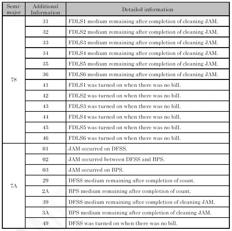
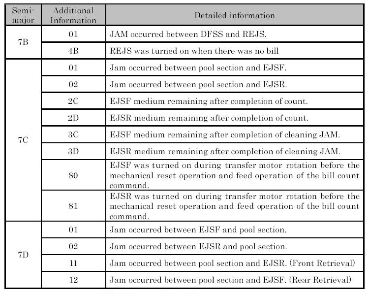
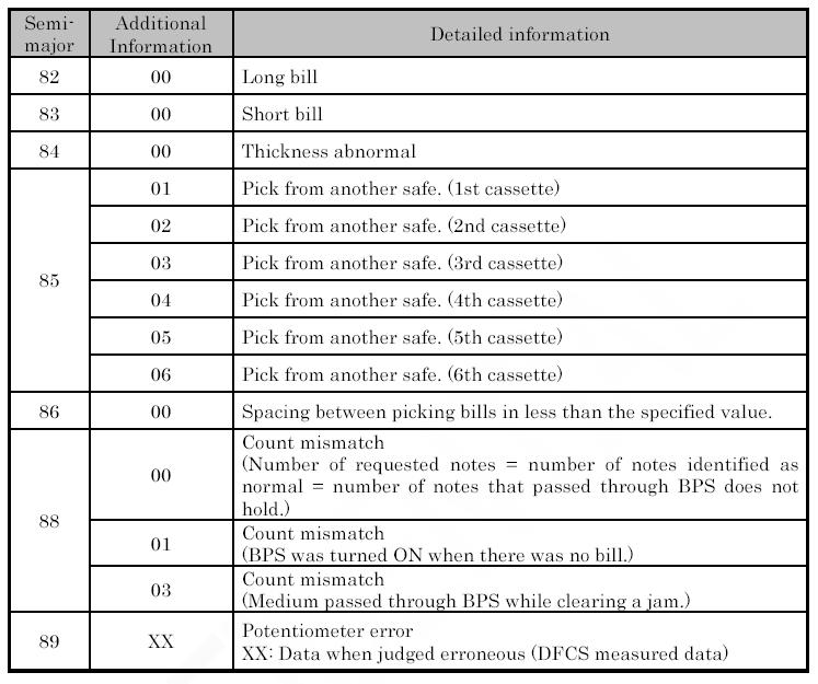
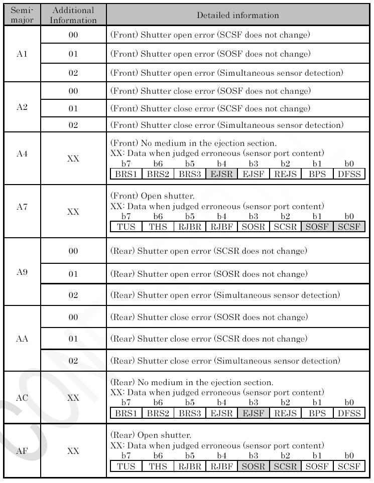
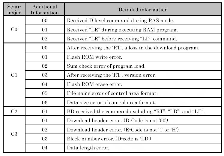
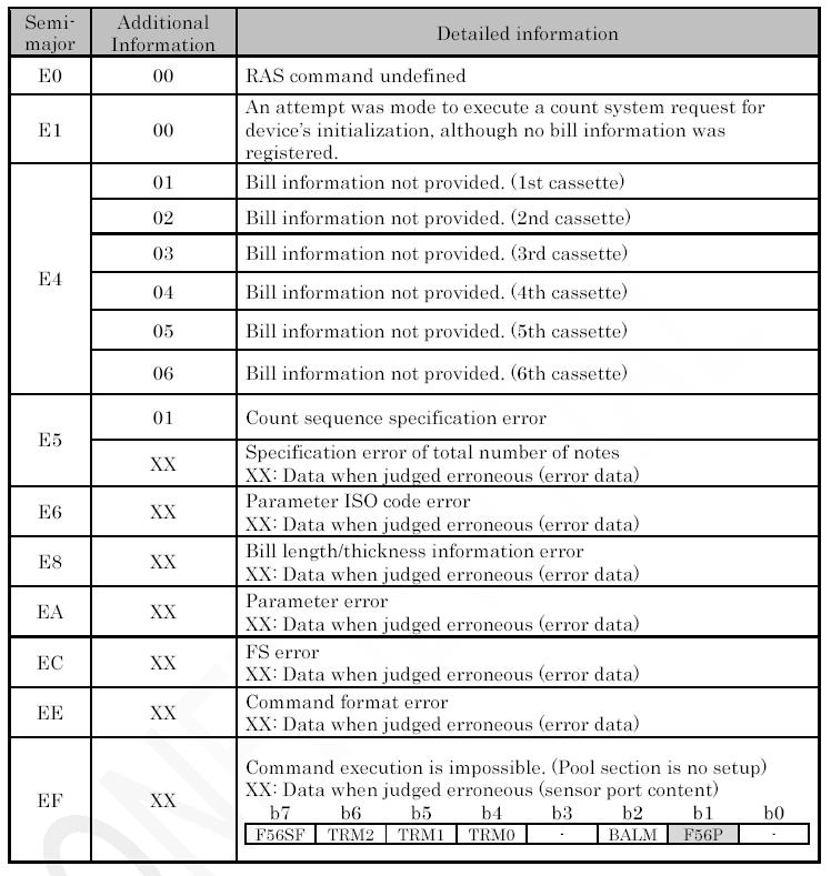
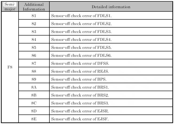
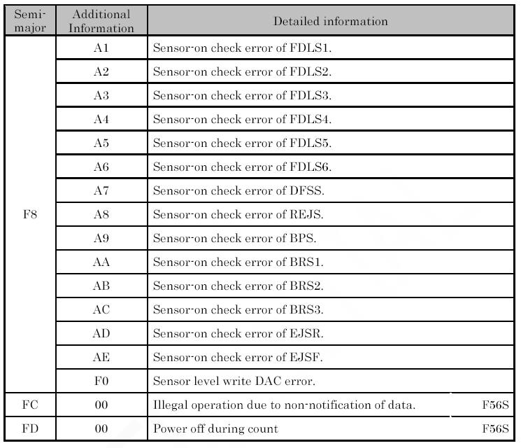
23 ERROR CODES Error Codes from the F53 bill dispenser are presented on the green LED character display located on the lower right-hand corner of the dispenser s PC Board (refer to figure on page 33). 3 RD Character 4 TH Character 5 TH Character 6 TH Character (1) All error codes are a sequence of 6 characters that are displayed, in order, for approximately 1 second each. Error codes always begin with Er as the first two characters. (2) The third character shows the position in which the error occurred, the fourth character shows more detailed information about the error, and the fifth and sixth characters give any additional information. (3) The tables on the following pages define all of the possible error codes on the F53. EXAMPLE: For the error 2 nd Cassette Pick Error, the display will flash: E-r repeatedly; one second per character. 23
24 24

25 25
26 26
27 27
28 28

29 29
30 30
31 31
32 32
33 33 LED Character Display
34 ROUTINE CLEANING & MAINTENANCE YEARLY Belts: Inspect whether the bill-carrying flat belts have become loose due to expansion, or are worn, cracked, or damaged in any way. If so, replace them with new belts. Cartridge Pick/Sub Rollers: Inspect the Pick and Sub Rollers in each bill cartridge. If they are worn, damaged, or have difficulty pulling bills out of the cartridge, replace them with new rollers. EVERY FOUR MONTHS (OR WHEN NEEDED) Bill Thickness Detection Lever: Check whether paper dust, or other dirt and grime has adhered to the thickness detection lever, or its attached metal rollers. Clean both sides of the lever and the rollers with a soft dry cloth. Sensors: Inspect all of the F53 s optical sensors for dirt, dust, or any other grime that could lead to impaired operation. Gently clean the sensors using ONLY a soft, dry, and lint-free cloth. Belts and Rollers: Clean all of the machine s belts and rollers, paying close attention to the bill-carrying belts and the Pick and Sub Rollers in each bill cartridge. Remove any dirt and grease from them using a soft, lint-free cloth soaked in isopropyl alcohol. 34
35 35
36 MKIV UNIVERSAL HOPPER INDEX PAGE 1. Coin box removal & assembly Exit window replacement Logic board replacement End plate removal Track plate removal 39 5a. Track plate Assembly 40 5b. Track plate Replacement 41 5c. Final drive gear replacement Gearbox assembly Motor replacement 42 SERVICE MANUAL To UN-jam the hopper, refer to sections 4 5b, pages
37 1. COIN BOX REMOVAL 1. Place the hopper in front of you as shown, (looking at the outside of the coin box ). 6. As the coin box is being removed, carefully slide the logic board out. The stirrer may stay with the coin box or fall onto the center plate. Refer to FIG Remove the 2 locking nuts, which hold the low level sense plate wires to the studs. 3. Remove the crimp & wire from the studs. Refer to FIG 1a. 4. Remove the 5 screws indicated (B), which hold the coin box to the center plate. ACCESS IS NOW AVAILABLE TO THE LOW LEVEL SENSE PLATES, THE MAIN PCB, THE EXIT WINDOW, THE MOTOR TERMINALS & PART OF THE WIRING LOOM. 1a. COIN BOX ASSEMBLY 1. Firstly, locate the stirrer in the coin box as shown in FIG Gently lift the coin box away from the rest of the hopper. (Refer to FIG 1b) NOTE: The logic board & stirrer are located in the coin box. 37
38 COIN BOX ASSEMBLY (cont.) 2. Line up the center plate & coin box as shown below. FIG 12a. 3. Route the ribbon cable as shown below. 4. Fit the logic board into slots shown below. 5. Feed the level sense wires through the slot shown below. 7. Align the center plate & coin box & push together. 8. Turn the hopper over & refit the screws. 9. Refit the level sense wires. 2. EXIT WINDOW REPLACEMENT 1. First, remove the coin box, section 1. This will then enable access to the exit window 2. Unscrew & remove the 2 fixing screws. (See FIG 4) 3. Remove the exit window from the center plate. 4. Unclip & remove the 10-way ribbon cable header. 6. Lift the centre plate to meet the coin box. FIG 12b & c. 5. To re-assemble, follow the above steps in reverse. 38
39 3. LOGIC BOARD REPLACEMENT 1. First, remove the coin box, section Holding the connector blanking plate gently lift the end plate away from the rest of the hopper. This will then enable access to the logic board. 5. To re-assemble, follow the above steps in reverse. 5. TRACK PLATE REMOVAL 1. First, remove the end plate, section way ribbon IDC socket (CONN 1): 2. Move the two ejector arms at right angles to & away from the connector, if fitted. 3. This should release the socket from the header. 4. Clasping the connector between thumb & forefinger, pull away from pin header. See FIG The elevator track & final drive gear can now be removed by lifting up & away from the center plate. 14-way crimp socket (CONN 2): 5. Gently unclip the friction lock from the connector housing. 6. Clasping the connector between thumb & forefinger, pull away from pin header. 7. The Logic Board is now released. 8. To re-assemble, follow the above steps in reverse. 4. END PLATE REMOVAL 1. Place the hopper in front of you as shown, (looking at the outside of the end plate ). Refer to FIG Remove the 9 screws indicated (B), which hold the end plate to the center plate. 3. Locate the position of the connector blanking piece. 39
40 5a. TRACK PLATE ASSEMBLY The following 3 sketches show how to take the track plate apart. The following 3 sketches show how to assemble the track plate. 40
41 5b. TRACK PLATE REPLACEMENT 1. The gray shaded area, in FIG 7b, is the track plate guide path. FIG 7b. 2. Once the track plate is in position, turn the track through to ensure it is seated in the guide path correctly. 5c. FINAL DRIVE GEAR REPLACEMENT 1. Once the elevator track is in place, the final drive gear can be fitted by placing the gear over its mounting spindle, while lining the teeth up with the secondary drive gear, adjust the elevator track so that the gear falls into place. (See FIG 7c) 2. The end plate can now be re-fitted. See section 4. 41
42 6. GEAR BOX ASSEMBLY 1. Remove the end plate. Section Remove the elevator track & final drive gear. Section Remove the gears in the order as shown in FIG 9. Access to the motor fixing screws is now possible. 5. To re-assemble, follow the above steps in reverse. 3. Remove the gearbox cover. 7. MOTOR REPLACEMENT 1. Remove the coin box. Section Unscrew the 2 motor fixing screws. FIG To re-assemble, follow the above steps in reverse. 2. Unsolder the red & black wires from the motor. NOTE: The black wire connects to the terminal marked with a RED dot. 3. Remove the end plate. Section Remove the track plate & final drive gear. Section 5 5. Remove the gearbox cover. 6. Disassemble the gearbox. Section 6. 42
43 # Motor # Motor Side Cover # Center Plate # End Plate #5A Coin Optic Board. #5B Optic ribbon cable. # Red track plates (16 per belt) # Logic board wire harness # Male 12 pin connector # Female 12 pin connector # Idler gear # Gear Box # Gear Shaft # Gear #1 Plastic # Gear #2 & 3 # Output gear # Gear #4 # Blanking Plate # Fixing screw # Cam Shaft Agitator Cam shaft bearing # Cam Agitator # Stirrer # Low level contact plate. # Mark IV PC logic board. #4 #18 #8 #6 #11 #17 #15 #10 #16 #12 #3 #5A #19 #14 #20 #13 #1 #21 #5B #23 #7 #22 #2 #18 43

44 MARS AE2600 SERIES 24VDC PARTS BREAKDOWN #8 PICTURE # #1 #2 #3 #4 #5 #6 #7 #8 #9 PART # AE AE AE AE AE AC1045 AE AE AE
45 CONTINUED PICTURE # #1 #2 #3 #4 #5 #6 #7 #8 PART # AE AE AE AE AE AE AE AE DESCRIPTION Gearbox Assy Tension Assy Tension Spring Tire/Wheel Assy Belt, Timing, (1 of 2)-143 Teeth Pulley, Compound Shaft, Pulley Belt, Timing, (1 of 2)-56 Teeth 45
46 CONTINUED PICTURE # #1 #2 #3 #4 PART # AE AE AE AE DESCRIPTION Main Chassis, Plastic Stacker Latch, Blue Spring, Stacker Latch Lower Housing Lift Spring 46
MKIV Universal Hopper Service Manual TSP053.doc Issue 2.1 June 2004
 This document is the copyright of Money Controls Ltd and may not be reproduced in part or in total by any means, electronic or otherwise, without the written permission of Money Controls Ltd. Money Controls
VALICHANGER OPERATIONS MANUAL SERIES AC1000/1001
 Fax:(954)917-5204 VALICHANGER OPERATIONS MANUAL SERIES AC1000/1001 Table of Contents SECT. A: SET-UP & INSTALLATION Uncrating & Setup 3 Mounting instructions 3-4 Filling the Hopper 4 Using the Dump Mode
AMERICAN CHANGER & HOFFMAN MINT
 AMERICAN CHANGER & HOFFMAN MINT We Are Changing the Industry 1400 N. W. 65 th Place, Fort Lauderdale, Florida 33309 T: (+1) 954-917-3009 F: (+1) 954-917-3079 www.americanchanger.com www.hoffmanmint.com
VALICHANGER OPERATIONS MANUAL SERIES AC400/500
 VALICHANGER OPERATIONS MANUAL SERIES AC400/500 American Changer Corp. Parts & Service:(888)741-9840 1400 NW 65 th Place Sales:(800)741-9840 Ft. Lauderdale, FL 33309 Fax:(954)917-5204 Internet Address:
Auto Sentry-eXP Maintenance. Revised 12/21/07
 Auto Sentry-eXP Maintenance Revised 12/21/07 Maintenance Procedures for Auto Sentry exp Bill Dispenser Credit Card Reader Bill Acceptor Bill Dispenser Maintenance Bill Dispenser Problem / Cause Bill Dispenser
JEEVES. JEEVES Installation Manual. Installation Manual The Easiest Do-It-Yourself Dumbwaiter on the Market
 1 888-323-8755 www.nwlifts.com JEEVES Installation Manual The Easiest Do-It-Yourself Dumbwaiter on the Market This manual will cover the installation procedure step-by-step. The installation of this dumbwaiter
Wittek Ball Dispenser Manual. Call or go online at to order!
 Wittek Ball Dispenser Manual Call 1-800-869-1800 or go online at www.wittekgolf.com to order! INTRODUCTION The 10K Signature Series Dispensers will vary with the individual characteristics of each range
Validator and Control Board Update Instructions for BC1
 Validator and Control Board Update Instructions for BC1 Installation Overview The update kit for the Rowe BC1 enables the changer to interface with a Mars AE/VN 120-volt validator. The validator determines
To Purchase This Item, Visit BMI Gaming
 Table of Contents General Operation. 3 How Slam-A-Winner plays How the Wheel Scores How the Ball Lift works Programming Options... 4-6 Troubleshooting Guide. 7-8 Parts Identification 9 Schematics 10-13
Maintenance Guide AZTEC BNF-2000 BILL ACCEPTOR PRIMARY COMPONENT PARTS
 AZTEC BNF-2000 Bill Acceptor Maintenance Guide October, 2007 October, 2007 Maintenance Guide JCM is a registered trademark of JCM American Corporation. All other product names mentioned herein may be registered
JBI Docupunch P33 Automatic Punch
 JBI Docupunch P33 Automatic Punch Instruction Manual Provided By http://www.mybinding.com http://www.mybindingblog.com TABLE OF CONTENTS SECTION I: INSTALLATION & TESTING: 1) Uncrating, Inspection & removal
TRIPLE PHONE CARD DISPENSER OPERATIONS MANUAL SERIES AC503/504-(V)
") TRIPLE PHONE CARD DISPENSER OPERATIONS MANUAL SERIES AC503/504-(V) American Changer Corp. Parts & Service:(888)741-9840 1400 NW 65 th Place Sales:(800)741-9840 Ft. Lauderdale, FL 33309 Fax:(954)917-5204
TRIPLE PHONE CARD DISPENSER OPERATIONS MANUAL SERIES AC503/504-(V) American Changer Corp. Parts & Service:(888)741-9840 1400 NW 65 th Place Sales:(800)741-9840 Ft. Lauderdale, FL 33309 Fax:(954)917-5204
SINGLE PHONE CARD DISPENSER OPERATIONS MANUAL SERIES AC501-(V)
") SINGLE PHONE CARD DISPENSER OPERATIONS MANUAL SERIES AC501-(V) American Changer Corp. Parts & Service:(888)741-9840 1400 NW 65 th Place Sales:(800)741-9840 Ft. Lauderdale, FL 33309 Fax:(954)917-5204 Internet
SINGLE PHONE CARD DISPENSER OPERATIONS MANUAL SERIES AC501-(V) American Changer Corp. Parts & Service:(888)741-9840 1400 NW 65 th Place Sales:(800)741-9840 Ft. Lauderdale, FL 33309 Fax:(954)917-5204 Internet
Service Manual Model L1000 Smart Lift
 Service Manual Model L1000 Smart Lift Form #1-147 Rev. 10/1/13 Table of Contents Parts Breakdown 3 Monthly Maintenance Checklist 5 Smart Lift Operating Instructions 7 Scale Calibration 8 Advanced Smart
Installation & Service Manual
 Installation & Service Manual for M² Sync Slideout Control Box #1510000122 CONTENTS Introduction Installation Installation Problems Program Mode Operation Mode Preventative Maintenance Fault Diagnostics
Installation and Service Manual M² Sync Room Slideout System without Room Lock Connectors on Control Box
 Installation & Service Manual M² Sync Room Slideout System w/o Room Locks: for Slideout Control Box# 1510000143 and 1510000198 Figure 1 01/13 Power Gear #3010002088 Rev. 0C Installation and Service Manual
Service Manual Model S800 Smart Stand
 Service Manual Model S800 Smart Stand Form #1-146 Rev. 10/3/13 Table of Contents Parts Breakdown 3 Monthly Maintenance Checklist 7 Smart Stand Operating Instructions 9 Scale Calibration 10 Advanced Smart
Service Manual. Model L500 and L600 Smart Lift. WARNING: Cancer and Reproductive Harm - Form #1-144 Rev.
 Service Manual Model L500 and L600 Smart Lift WARNING: Cancer and Reproductive Harm - www.p65warnings.ca.gov. Form #1-144 Rev. 2/5/19 Table of Contents Parts Breakdown 3 Monthly Maintenance Checklist 5
Service Manual Model S400 and S500 Smart Stand
 Service Manual Model S400 and S500 Smart Stand Form #1-145 Rev. 10/3/13 Table of Contents Parts Breakdown 3 Monthly Maintenance Checklist 7 Smart Stand Operating Instructions 9 Scale Calibration 10 Advanced
GENESIS KIT for Rowe. INSTALLATION: BC12R, 1400 Special tools needed drill and a 5/32 bit
 Page 1 of 5 GENESIS KIT for Rowe INSTALLATION: BC12R, 1400 Special tools needed drill and a 5/32 bit THE COIN DETECTOR LIGHT(S) ON THE COIN DISPENSER FRAME NEED TO BE THE NEWER RED LED TYPE. IF YOU HAVE
Troubleshooting Guide
 Troubleshooting Guide 1 TABLE OF CONTENTS How To Use Guide...3 Figure 1...4 Figure 2......5 Electrical Problems...6 Vacuum Motor Problems...8 Fragrance Delivery Problems...10 Timer Problems...15 Coin/Bill
IMPORTANT! DO NOT THROW AWAY THE SHIPPING CARTON AND PACKING MATERIAL
 Operator s Manual IMPORTANT! DO NOT THROW AWAY THE SHIPPING CARTON AND PACKING MATERIAL ii Table of Contents Operator Safety... 1 Introduction... 2 Unpacking and Setup... 3 Unpacking... 3 Setup... 4 ROCKET
CM1000C CM1800C ChangeMakers. Operator s Manual. Seaga Manufacturing, Inc. 700 Seaga Drive Freeport, IL USA
 CM1000C CM1800C ChangeMakers Operator s Manual Seaga Manufacturing, Inc. 700 Seaga Drive Freeport, IL USA 61032 www.seagamfg.com INTRODUCTION Congratulations on the purchase of your new ChangeMaker. This
MC-CRX. Bill Acceptor Card Reader Combo. Operation & Service Manual
 MC-CRX Bill Acceptor Card Reader Combo Operation & Service Manual TABLE OF CONTENTS SECTION 1: GENERAL INFORMATION Introduction...4 Features...4 For Records...4 After Unpacking...4 Naming Convention...5
Inteli-Lift GEN II DUMBWAITER
 1 877-345-4387 530-295-4900 www.eilifts.com Inteli-Lift GEN II DUMBWAITER The Easiest Dumbwaiter system on the Market Fully UL Certified Dumbwaiter Systems UL File # SA32120 This manual will cover the
LIPPERTCOMPONENTS, INC.
 LIPPERTCOMPONENTS, INC. SCHWINTEK INWALL SLIDEOUT SYSTEM OPERATION AND SERVICE MANUAL Contents I. Controls 1-1 System components 1 1-1A versions C1 & C2 2 1-2 Motor wiring harness connections 3 1-3 Extend
Installation and Service Manual M² Sync Room Slideout System without Room Lock Connectors on Control Box
 Installation & Service Manual M² Sync Room Slideout System w/o Room Locks: for Slideout Control Box# 1510000143 and 1510000198 Figure 1 01/13 Power Gear #3010002088 Rev. 0C Installation and Service Manual
FD 342 Document Folder
 FD 342 Document Folder 6/2010 OPERATOR MANUAL FIRST EDITION TABLE OF CONTENTS SUBJECT PAGE DESCRIPTION 1 SPECIFICATIONS 1 UNPACKING 2 SETUP 2 CONTROL PANEL 3 OPERATION 4 SETTING CUSTOM FOLDS 5 BATCH COUNTING
E-LIFT II+ SYSTEM WITH SPRING LEVER FOR A-SERIES AND FULL FRAME LOOMS
 Congratulations on your purchase of the E-Lift II+ system. This system replaces the action of treadling, eliminating leg strain and fatigue. When you activate the Foot Switch, the motor turns, and selected
FD 120 Card Cutter MAINTENANCE MANUAL. MyBinding.com 5500 NE Moore Court Hillsboro, OR Toll Free: Local: /2011
 FD 120 Card Cutter 5/2011 MAINTENANCE MANUAL SAFETY PRECAUTIONS Always observe the cautions and warnings given below to prevent personal injury or property damage. The degree of danger and damage that
Turn Signal Kit Installation Instructions for Model A Fords & Other Antique Vehicles
 Turn Signal Kit Installation Instructions for Model A Fords & Other Antique Vehicles Lifetime Technical Support support@logolites.com 770-476-7322 www.logolites.com Manual 100-0005N Thank you for purchasing
TERMINATOR User Manual
 TERMINATOR User Manual TERMINATOR User Manual Table of Contents Section Page 1 2 3 4 5 6 7 8 9 10 11 12 13 14 15 16 17 18 19 20 21 Introduction Safety Precautions Features and Benefits Overview of the
Sure-Feed Engineering Inc. SE-900-EI. Operation & Parts Manual
 . SE-900-EI Operation & Parts Manual SE 900 EI OWNERS MANUAL Table of Contents 1. Installation guide 2. Set-up instructions 3. Operation instructions 4. Cleaning 5. Troubleshooting 6. Parts manual 7. Electrical
Roll Up Door Operator
 INSTRUCTIONS & OWNERS MANUAL Roll Up Door Operator 2 INDEX Preparation before installation 4. Terms and definitions 5. Pictures & names of parts 6. Mounting the weight bar 7. Installing the operator 7.
AIR CLEANERS Model MC 3000 OWNER S MANUAL CAUTION Read complete instructions before operating. Please file for future reference.
 AIR CLEANERS Model MC 3000 OWNER S MANUAL CAUTION Read complete instructions before operating. Please file for future reference. MODEL MC 3000 SPECIFICATION Input Volts: 208-230/430 VAC, 60Hz, 3 Phase
Maintenance Adjustments
 4 Maintenance and Adjustments Chapter Contents Cleaning the Printer and Paper Handling Accessories..... 158 Cleaning the HP Digital Copier....................... 161 Cleaning ADF and Glass............................
TALON 22 WHEEL & TALON X-TREME 38 WHEEL TPMS, UP to 188 PSI PRESSURE AND TEMPERATURE WITH CAP OR FEEDTHRU SENSORS
 TALON 22 WHEEL & TALON X-TREME 38 WHEEL TPMS, UP to 188 PSI PRESSURE AND TEMPERATURE WITH CAP OR FEEDTHRU SENSORS Thank you for your purchase of The HawksHead TALON OR TALON X-TREME TPMS System With ease
Alliance Towel Dispensing System. Operation Manual
 Alliance Towel Dispensing System Operation Manual Alliance Towel Dispensing System Table of Contents Safety Information... page 2 Mounting Instructions... page 3 Towel Loading Instructions... page 7 Settings...
XR Conveyor Maintenance Guide
 XR Conveyor Maintenance Guide EN-0035 Rev. A XR Conveyor Maintenance Guide www.qdraw.com Table of Contents 05/20/2009 Overview Page 3 XR Conveyor Assembly Page 4 General Information Exploded View of an
DESIGNED BY EXPERIENCE PLASTIC SPHERE DISPENSER USER MANUAL. Manufactured by PSDS, Inc. for sole distribution by:
 DESIGNED BY EXPERIENCE PLASTIC SPHERE DISPENSER USER MANUAL Manufactured by PSDS, Inc. for sole distribution by: AEROSTAT, INC. 8830 AIRPORT BLVD LEESBURG, FL 34788 WEBSITE: AEROSTATINC.COM TEL: 352 787-1348
TOYOTA RAV TVIP V3
 Section I Installation Preparation Part Number: 08586-4A872 Section I Installation Preparation Kit Contents Item # Quantity Reqd. Description 1 1 Wire Harness 2 1 Status Monitor 3 1 Piezo Buzzer 4 1 V3
INSTALLATION AND OPERATING INSTRUCTIONS
 ASTRO ENVELOPE FEEDER AMC-2000 INSTALLATION AND OPERATING INSTRUCTIONS INTRODUCTION Thank you for purchasing the Astro Envelope Feeder. It is fast, efficient, reliable, and designed to provide many years
Customer Name: Serial Number: Y-Axis Stall
 Technician Name: Date: Technician Name: Date: Customer Name: Serial Number: Y-Axis Stall Issue Explanation and Background Each drive motor on the machine (the x, y and z axes motors) has a sensor called
XPS-ProFeed Shuttle SERVICE MANUAL. Revised:
 XPS-ProFeed Shuttle SERVICE MANUAL Revised: 9-14-15 RENA SYSTEMS INC. 910 East Main Street; Suite 200 Norristown, PA 19401-4110 Phone: (610) 650-9170 Fax: (610) 270-3947 Web Site: www.renausa.com SAFETY
INSTALLATION AND OPERATING INSTRUCTIONS
 ASTRO ENVELOPE FEEDER AMC-2000 INSTALLATION AND OPERATING INSTRUCTIONS INTRODUCTION Thank you for purchasing the Astro Envelope Feeder. It is fast, efficient, reliable, and is designed to give you many
Motion System Components Diagram. Note: #2 Mirror Cover and X-Axis Motor Cover have been removed for visibility. Maintenance.
 Professional Laser System PLS3.75, PLS4.75, PLS6.75 and PLS6.150D Keeping the laser system clean will ensure the highest quality engraving. A clean laser system is the best performing laser system. The
ISO1000R Service Manual SALES: CUSTOMER SERVICE:
 ISO1000R Service Manual SALES: 800-278-3933 CUSTOMER SERVICE: 800-745-1373 Revision: August 1999 Table of Contents Section Page I. Overview 2 II. Troubleshooting Tables 3 III. Maintenance Procedures Procedure
Models- 8105, Commercial Vacuums. Product Information Product Dimensions. Important Safety Instructions
 Models- 8105, 9225 9235 Commercial Vacuums Page 2 Page 3 Page 4 Page 5 Page 5-8 Page 9 Page 10 Page 10 Page 11 Page 12-19 Page 20-24 Product Information Product Dimensions Specifications Important Safety
TRITON ERROR CODES ERROR CODE MODEL SERIES DESCRIPTION RESOLUTION
 0 8100, 9100, 9600, 9610, 9615, 9640, No errors 9650, 9700, 9710, 9705, 9750, RL5000 (SDD),RL5000 (TDM), RT2000, 9800, MAKO, SuperScrip 1 9615 Unsolicited note channel 1 2 9615 Unsolicited note channel
INSTALLATION AND OPERATING INSTRUCTIONS
 ASTRO ENVELOPE FEEDER AMC-2000-5 FOR RYOBI 3302 / ITEK 3985 (2 COLOR) INSTALLATION AND OPERATING INSTRUCTIONS INTRODUCTION Thank you for purchasing the Astro Envelope Feeder. It is fast, efficient, reliable,
Instruction Manual for the. E-SL 450 Series
 Instruction Manual for the E-SL 450 Series Estate Slide Summary of Functions The Estate Slide is only to be used for vehicular Slide gates in a Class I setting. Class I: A vehicular gate opener (or system)
CABINET REEL OPERATING INSTRUCTIONS
 CABINET REEL OPERATING INSTRUCTIONS MODELS 15, 25, 40 & 60 SERIES RAPID-AIR CORPORATION 4601 KISHWAUKEE ST. ROCKFORD, IL 61109-2925 Phone: (815) 397-2578 Fax: (815) 398-3887 Web Site: www.rapidair.com
Preparing The Printer For Maintenance
 Chapter 4 Preparing The Printer For Maintenance Preparing The Printer For Maintenance WARNING IMPORTANT Unplug the printer power cord from the printer or power outlet before you do any maintenance procedure.
Inlet Controller TC5-ITA USER'S MANUAL. M rev. 02 K rev. 00
 Inlet Controller TC5-ITA USER'S MANUAL M 890-00047 rev. 02 K 895-00458 rev. 00 TABLE OF CONTENTS PRECAUTIONS... 3 FEATURES... 4 LOCATION OF THE CONTROLS... 5 Status Leds...5 Internal Switches...6 INSTALLATION
Model DS7060 Handrail Scale. User Manual
 Model DS7060 Handrail Scale User Manual Doran Scales, Inc. 1315 Paramount Pkwy Batavia, IL 60510 USA 1-800-264-4107 www.doranmedical.com MAN0302 Revision 0.0 TNW 2/20/2013 Section 1. Unpacking and Installation...
RS4000 Setup. Before you install the RS4000 system, check to ensure that nothing was damaged or lost during shipping.
 RS4000 Setup Before you install the RS4000 system, check to ensure that nothing was damaged or lost during shipping. If anything is damaged or missing, contact your salesman immediately. Mount Components
SERVICE GUIDE For WARN PULLZALL 120Vac P/N &
 SERVICE GUIDE For WARN PULLZALL 120Vac P/N 885000 & 885001 REPAIR / REPLACEMENT INSTRUCTIONS TROUBLE SHOOTING GUIDE 987604A2.doc Page 1 of 48 WARNING This guide identifies potential hazards and has important
SX1000 Service Manual SALES: CUSTOMER SERVICE:
 SX1000 Service Manual SALES: 800-278-3933 CUSTOMER SERVICE: 800-745-1373 Revision: August 1999 Table of Contents Section Page I. Overview 2 II. Troubleshooting Tables 3 III. Maintenance Procedures Procedure
Table of Contents. General Operation. 3 How Slam-A-Winner plays How the Wheel Scores How the Ball Lift works Programming Options...
 61-MAN-B Table of Contents General Operation. 3 How Slam-A-Winner plays How the Wheel Scores How the Ball Lift works Programming Options... 4-6 Troubleshooting Guide. 7-8 Parts Identification 9 Schematics
User Manual Solar Charge Controller 3KW
 User Manual Solar Charge Controller 3KW Version: 1.3 CONTENTS 1 ABOUT THIS MANUAL... 1 1.1 Purpose... 1 1.2 Scope... 1 1.3 SAFETY INSTRUCTIONS... 1 2 INTRODUCTION... 2 2.1 Features... 2 2.2 Product Overview...
MODEL MVX-2011 TANK MOUNT SPEEDOMETER/TACHOMETER
 MODEL MVX-2011 TANK MOUNT SPEEDOMETER/TACHOMETER Wiring Diagram The MVX-2011 gauges will work on 2011-up Softail models with 5 gauges or 2012-up Dyna models with 5 gauges. It is a direct plug in on these
B-RAD Select USER MANUAL TABLE OF CONTENTS
 TABLE OF CONTENTS TABLE OF CONTENTS... 1 MANUAL REVISION HISTORY... 2 IMPORTANT SAFETY NOTICE... 3 1.0 General Information... 5 1.1 System Components... 5 1.2 Specifications... 5 1.2.1 Torque Ranges...
SE-600-P Eco-Series. Operation & Parts Manual
 SE-600-P Eco-Series Operation & Parts Manual SE 600 PC & PS SERIES OWNERS MANUAL Table of Contents 1. Set-up instructions 2. Bridge-Tramming Procedure 3. Operation instructions 4. Cleaning 5. Troubleshooting
OPERATING MANUAL Digital Diesel Control Remote control panel for WhisperPower generator sets
 Art. nr. 40200261 OPERATING MANUAL Digital Diesel Control Remote control panel for WhisperPower generator sets WHISPERPOWER BV Kelvinlaan 82 9207 JB Drachten Netherlands Tel.: +31-512-571550 Fax.: +31-512-571599
Magnetek DSD 412 Drive
 DRIVE STARTUP MANUAL Magnetek DSD 412 Drive Induction Motor Installation www.smartrise.us 2601 Fair Oaks Blvd., Sacramento, CA 95864 916.457.5129 Magnetek DSD 412 Drive EQUIPMENT/SETTINGS VERIFICATION
Service Manual. (Cash Dispensing Module) : 38 pages (including cover) Date : Version : V2.1. PULOON Technology Inc.
 : 38 pages (including cover) Date : Version : V2.1. PULOON Technology Inc.") Service Manual Model Total Page : LCDM-2000 (Cash Dispensing Module) : 38 pages (including cover) Date : 2001. 12 Version : V2.1 = Contents = 1. Functional Description 1-1. Instruction 1-2. Specification
Service Manual Model Total Page : LCDM-2000 (Cash Dispensing Module) : 38 pages (including cover) Date : 2001. 12 Version : V2.1 = Contents = 1. Functional Description 1-1. Instruction 1-2. Specification
CONTROL BOX. Wiring the control box into the vehicle. +12V
 CONTROL BOX Once the display panel is in place, mount the control box within the connecting cable's distance (approximately 3 feet) and secure to the underside of the dashboard. This case does not have
3 in 1 TRAIL CHARGER with LOCKOUT
 Owner s Manual P/N: 283821 500 3 in 1 TRAIL CHARGER with LOCKOUT 283821 01 Version 2.04 07/05/2011 Owners Manual Operation Installation Wiring Diagram Troubleshooting Parts Breakdown 1 GENERAL OPERATION
MC2500. Installation and Operation Manual
 MC2500 Installation and Operation Manual Important: This manual contains specific cautionary statements relative to worker safety. Read this manual thoroughly and follow as directed. It is impossible to
MICRO-AIR AIR CLEANER INSTALLATION AND OPERATION MANUAL. MX3510 Includes Installation, Operation, and Service Instructions CAUTION
 MICRO-AIR AIR CLEANER INSTALLATION AND OPERATION MANUAL MX3510 Includes Installation, Operation, and Service Instructions CAUTION Read complete instructions before operating. Please file for future reference.
Steeda S550 Mustang Front Coilover Installation Instructions For Part:
 Steeda S550 Mustang Front Coilover Installation Instructions For Part: 555-8170 Tools required 1. Jack 2. Jack stands 3. Torque Wrench 4. 10mm wrench 5. 11mm wrench 6. 17mm wrench 7. 18mm socket 8. Plastic
Setup and Programming Manual
 Microprocessor and Handy Terminal Setup and Programming Manual Versions U04 to U19 for Sliding Door Systems P/N 159000 Rev 7-2-07 The manufacturer, NABCO Entrances, Inc. suggests that this manual be given
INSTALLATION INSTRUCTIONS
 0711016 Page 1 INSTALLATION INSTRUCTIONS ELECTRONIC DEADBOLT WITH KEYPAD latch 2-3/8 Your latch is now set 2-3/8 (60mm) backset latch 2-3/4 2-3/4" (70mm) 2-3/8" (60mm) Cylindrical cover Extension plate
PL900 ILLUMINATOR. Fiber-Lite. Operation Manual. Setup. Fiber Optic Connection A PRODUCT OF DOLAN-JENNER INDUSTRIES. Voltage Selection:
 PL900 ILLUMINATOR A PRODUCT OF DOLAN-JENNER INDUSTRIES Setup Voltage Selection: Operation Manual Read and review the instructions on the label covering the power entry module and the instructions in this
XPS-ProFeed Shuttle SERVICE MANUAL. Revised:
 XPS-ProFeed Shuttle SERVICE MANUAL Revised: 1-14-15 RENA SYSTEMS INC. 910 East Main Street; Suite 200 Norristown, PA 19401-4110 Phone: (610) 650-9170 Fax: (610) 270-3947 Web Site: www.renausa.com SAFETY
Instruction Manual AVTM for. Strip Chart Recorder Catalog Nos and
 AVTM220003 Rev. B January 2003 Instruction Manual AVTM220003 for DC µa Strip Chart Recorder Catalog Nos. 220003 and 220003-47 PO Box 9007 Valley Forge, PA 19485-1007 U.S.A. 610-676-8500 Shipping Address:
DESCRIPTION & OPERATION
 DESCRIPTION & OPERATION 1998-99 SUSPENSION Electronic - Real Time Damping - Corvette The Real Time Damping (RTD) system automatically controls vehicle ride by independently controlling a damper solenoid
Dispenser Communication Error Codes for units containing the DeLaRue SDD-1700 feeders only
 53 31.1.1 Dispenser Communication Error Codes for units containing the DeLaRue SDD-1700 feeders only 001 No acknowledgment received. 002 Command transmit time-out. 003 Command response receive time-out.
SureFire Drives and Harnesses for use with John Deere Dry Rate Controller
 396-001640 SureFire Drives and Harnesses for use with John Deere Dry Rate Controller & SureFire Dry Fertilizer Control Components 396-001640 John Deere Rate Controller Dry Instructions Page 1 02/23/2012
Table of contents. Game Play. Game Set-up. Technical Description. Programming. Error Codes. Electronic Components. Game Specifications.
 Table of contents Game Play Game Set-up Technical Description Programming Error Codes Electronic Components Game Specifications Parts 2 Red Hot X-Treme 7s Game Play The object of Red Hot X-Treme 7s is
2001 Chevrolet Corvette ACCESSORIES & EQUIPMENT Remote Keyless Entry Systems - Corvette
 DESCRIPTION 2001 ACCESSORIES & EQUIPMENT Remote Keyless Entry Systems - Corvette Remote Keyless Entry (RKE) system is controlled by Remote Function Actuation (RFA) system. Transmitter allows remote control
WARNING. Important Notice
 CAL (Color AquaLuminator ) Light and Return Water Flow for Above Ground Pools Owners Manual IMPORTANT SAFETY INSTRUCTIONS READ AND FOLLOW ALL INSTRUCTIONS SAVE THESE INSTRUCTIONS Table of Contents SECTION
Tooling Assistance Center
 Safeguards are designed into this application equipment to protect operators and maintenance personnel from most hazards during equipment operation. However, certain safety precautions must be taken by
TOSHIBA Thermal Printer B-SX6T/SX8T SERIES. Maintenance Manual. Document No. EO Original Mar., 2006 (Revised ) PRINTED IN JAPAN
 PRINTED IN JAPAN") TOSHIBA Thermal Printer B-SX6T/SX8T SERIES Maintenance Manual Original Mar., 2006 (Revised ) Document No. PRINTED IN JAPAN TABLE OF CONTENTS Page 1. UNPACKING--------------------------------------------------------------------------------------------------------
TOSHIBA Thermal Printer B-SX6T/SX8T SERIES Maintenance Manual Original Mar., 2006 (Revised ) Document No. PRINTED IN JAPAN TABLE OF CONTENTS Page 1. UNPACKING--------------------------------------------------------------------------------------------------------
The function of this Dynamic Active Probe has divided into three preferences on the screen main Menus:
 1.0 Introduction: This probe is designed to provide an additional help to automotive technicians in trouble shooting of electrical circuits problems in the car. Apart from using the normal multi tester,
INSTALLATION INSTRUCTIONS
 INSTALLATION INSTRUCTIONS [1] Description: Tow Hitch Wire Harness Kit [2] Application: Nissan Rogue Note: Tow Harness application is limited to specific vehicle option packages that include tow harness
DEFENDER USER MANUAL
 Where The Money Meets The Machine PO Box 5128, 400 Regency Drive, Glendale Heights, IL 60139-5128 VOICE: 630/924-7070 1-800-323-6498 FAX: 630/924-7088 DEFENDER USER MANUAL Interchangeable with existing
Safe-T-element Installation Instructions
 Safe-T-element Installation Instructions For: PTI STEZA (2x2 Burner Configuration) & PTI STEZB (3x1 Burner Configuration) Revision K (May. 3 2012) TABLE OF CONTENTS 1. PREPARATION... 3 1.1 General Safety
MD10. Engine Controller. Installation and User Manual for the MD10 Engine Controller. Full Version
 MD10 Engine Controller Installation and User Manual for the MD10 Engine Controller. Full Version File: MartinMD10rev1.4.doc May 16, 2002 2 READ MANUAL BEFORE INSTALLING UNIT Receipt of shipment and warranty
Z TECHNICAL INSTRUCTIONS
 ÍNDICE: Z40 2.0 TECHNICAL INSTRUCTIONS 1.- Error list 2.- Replace the control board 3.- Opening the machine 4.- Replace the power board 5.- Dismantling motor and gear box 6.- Assembly of gear box 7.- Pushing
SPACESAVER EC-300 A ELECTRICS
 INSTALLATION INSTRUCTIONS SPACESAVER EC-300 A ELECTRICS SECTION I TOP MOUNTED ELECTRICS SECTION II FACE PANEL MOUNTED ELECTRICS SECTION III ZFS INSTALLATION INSTRUCTIONS This symbol indicates a connection
CONTROLLER DIAGNOSTIC GUIDE
 Proprietary tice: This document contains proprietary information which not to be reproduced, transferred, to other documents, disclosed to others, used for manufacturing or any other purpose without the
MODEL MCL-3212 SPEEDOMETER/TACHOMETER for 2012 up Dyna and Softail with 4 gauge
 MODEL MCL-3212 SPEEDOMETER/TACHOMETER for 2012 up Dyna and Softail with 4 gauge IMPORTANT NOTE! This gauge has an odometer preset option that is only available one time in the first 100 miles (160km) of
ERROR RECOVERY ERR R O C D O ES / REC V O E Y R PR C O EDURES E
 ERROR RECOVERY ERROR CODES / RECOVERY PROCEDURES Error Code TDM 00/50 Mech 0 (MiniMech) Meaning Recovery Procedure X Feed failure 4 X Mistracked note at feed 5 X Mistracked note at double detect X Mistracked
SE-1200-MP ECO - SERIES
 Inc. SE-1200-MP ECO - SERIES Operation & Parts Manual SE 1200 MP ECO -SERIES OWNERS MANUAL Table of Contents 1. Installation guide 2. Set-up instructions 3. Operation instructions 4. Cleaning 5. Troubleshooting
INSTALLATION MANUAL STEP SLIDER BD-SS-200-JK4. Made in the USA. Front Bracket Middle Bracket Rear Bracket. Tools Required
 Made in the USA INSTALLATION MANUAL STEP SLIDER BD-SS-200-JK4 Description Quantity Electric Step Slider (Pair) 2 Front Bracket Middle Bracket Rear Bracket Bump stop plate with VHB backing 2 Wiring harness
SECTION G2: CABLE PROCESSOR MODULE MAINTENANCE
 SECTION G2: CABLE PROCESSOR MODULE MAINTENANCE Cable Processor Module overview WARNING! When tipping the Cable Processor Module back, (after removing the toggle arm pin), use extreme caution not to drop
OPERATION AND PARTS MANUAL
 OPERATION AND PARTS MANUAL MODEL NUMBER : PART NUMBER : GTL 1110 1900-0510 SERIAL NUMBER : BAYNE MACHINE WORKS, INC. PHONE: (864) 288-3877 910 FORK SHOALS ROAD TOLL FREE: (800) 535-2671 GREENVILLE S.C.,
Rollstar Shade Installation Instructions
 Rollstar Shade Installation Instructions All Lifting Systems Inside or Outside Mount Thank you for purchasing your new Rollstar shade. It has been custom-made from the highest quality materials to the
RR Concepts. The StationMaster can control DC trains or DCC equipped trains set to linear mode.
 Jan, 0 S RR Concepts M tation aster - 5 Train Controller - V software This manual contains detailed hookup and programming instructions for the StationMaster train controller available in a AMP or 0AMP