TALON 22 WHEEL & TALON X-TREME 38 WHEEL TPMS, UP to 188 PSI PRESSURE AND TEMPERATURE WITH CAP OR FEEDTHRU SENSORS
|
|
|
- Gary Reed
- 5 years ago
- Views:
Transcription


1 TALON 22 WHEEL & TALON X-TREME 38 WHEEL TPMS, UP to 188 PSI PRESSURE AND TEMPERATURE WITH CAP OR FEEDTHRU SENSORS Thank you for your purchase of The HawksHead TALON OR TALON X-TREME TPMS System With ease of installation and a large clear LCD display, with built in rechargeable lithium battery, the monitor has an automatic backlight for both day and night use. The monitor can handle up to 22 wheels for the TALON and 38 wheels for the TALON X-TREME, by the addition of extra sensors beyond the 4 wheel base system. High and low pressure warnings along with high temperature warnings can be set by the user. The monitors gives both visible and audible alerts for High pressure, Low Pressure, Rapid pressure drop and high temperature. Pressure and Temperature units can be displayed in PSI, Bar and Temperature in degrees F & C. Pressures can be set to a different pressure setting for each axle, so additional towed trailers etc are no problem.
.")

2 The long range Cap and Feed Through sensors for this system can reach up to 45 feet vehicle distance without a booster and are easy to install by simply screwing on to the vehicles tire valves, We do recommend the use of metal valve stems for this system and we do offer optional Stubby metal tire valves for (size.625 &.453 valve size applications up to 100psi). The Feed Through sensors do not have to be removed to add air. The TALON Systems have replaceable sensor batteries in both style of sensors so there is no need to throw them away when the battery levels drop, just simply replace them with a generic CR1632 battery. Each sensor comes with a security screw lock should you wish to lock the sensors to the valve stem. These systems offer ease of installation and operation that you would expect with a high grade TPMS.

3 MONITOR Charge the Monitor for at least 4 hours before set up or plug the power cord into the monitor and vehicle. The lithium battery inside the monitor has a battery life of 60 driving hours when fully charged. Leave the monitor switched on when charging. An Icon shows when battery needs charging. The Power switch is on the side of the monitor. The monitor will stay on when a charging cable is connected. OPTIONAL BRACKET MOUNT SETTING THE SYSTEM 1 SET YOUR TIRE PRESSURES WHEN COOL USING A QUALITY GAUGE 2 In Standby mode, press the SET BUTTON for 3 seconds and release it when you hear it BEEP once 3 Press the SET BUTTON repeatedly to cycle through to the parameter you wish to set. Press the + and - Buttons to adjust to your desired setting. 4 After you have selected all settings press the SET Button for 3 Seconds and release after you hear the BEEP and your settings are saved 5 If you do not press any button for 1 minute the monitor will return to the Standby mode without storing any data 6 Factory Presets are as follows. Pressure (PSI) High Pressure (175PSI) Low Pressure (100PSI) TEMP (Degrees C) High Temp (70C/158F) 7 To restore Factory Defaults. Turn off the Monitor, Press the SET Button and Turn On the Monitor at the same time. The RED light will flash and factory setting will be restored. 8 The X-TREME 38 wheel system monitor will show the Pressure & Temperature in a reverse position.

4 NOTE IF YOU CANNOT REDUCE THE LOW SETTING LOW ENOUGH FOR YOUR NEEDS, FIRSTLY REDUCE THE HIGH SETTING THIS WILL ALLOW THE LOWER SETTING LEVEL TO BE REDUCED. IF YOU DO NOT INTEND TO USE ALL 22 WHEEL POSITIONS SIMPLY BYPASS ANY WHEELS THAT YOU DO NOT INTEND TO USE IN YOUR CONFIGURATION. NON USED WHEELS WILL DISAPEAR FROM THE MONITOR DISPLAY AFTER SETUP
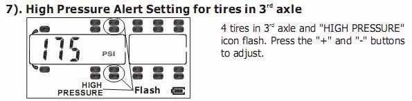
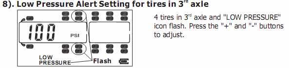
5

6 REPLACING THE SENSOR BATTERY The cap or feed through sensors supplied with the system already have batteries (CR1632) installed. If storing the system remove all the sensors and note or mark their position for reinstallation on the same wheel. The sensors do not use battery power when there is no air pressure applied to them. always replace any valve caps on feed through sensors. 1 Unscrew the cover 2 Remove the battery 3 Insert new battery + upwards


7 SENSOR INSTALLATION This should be done one at a time when you read Programming the Sensors below, do not just screw them all on at once. Remove any existing tire valve caps and screw the sensor on the valve, ensure the locking screw is backed off enough to allow the sensor to be screwed on without it rubbing the threads. Place a small amount of anti-seize or WD40 on the valve threads ensuring none enters the valve or sensor to stop any galvanic action. Hand tighten the sensor do not use any wrenches or tools to tighten. The locking screw can be tightened if required as a security measure. Ensure you keep the hex wrench to remove the locking screws. Programming the Sensors This is to tell the monitor on which wheels you are placing the sensors. After you have set all the parameters on the monitor 1 In Standby mode press the CODE button for 3 seconds until the monitor beeps. 2 The monitor will then flash on the right front wheel icon and because there is not yet any sensor code entered will show FFF FFF on the monitor. 3 With the monitor in hand, Go to the Right Front Wheel and screw on a sensor. 4 After the sensor has been hand tightened on the right front wheel the monitor will beep and the monitor will show that sensors code number on the screen as in the next picture. To delete the sensor if needed press the SET button for 3 seconds until it beeps and the code changes back to FFF FFF 5 The monitor now knows there is a sensor on that wheel and will monitor it within your set parameters 6 Press the + Button or - Button and move to the next wheel and follow the same procedure with another sensor. 7 Continue this procedure until all your sensors are installed, bypass any wheels you do not wish to use on the monitor 8 Please note it may take a few seconds for the monitor to detect the sensor 9 After all sensors are coded press the CODE button for 3 seconds to get out of the CODE setup 10 The monitor will go into standby mode if no buttons are pressed within 3 minutes Ensure you place sensors on the exact wheel you programmed on the monitor, Do not install the sensor on the inside dually of an axle, if you programmed the outside dually to be used. If you make this mistake you will get an alarm in standby mode due to pressure settings not been set correctly etc. MONITOR DISPLAY After the sensors have all been installed and the system is in standby mode the pressures and temperatures for each wheel will be displayed on the monitor in about 2-3 minutes. Mount the monitor away from other electronic devices such as a GPS and keep out of the hot sun. When in normal use the monitor display will automatically scroll through each monitored tire one by one showing its current pressure and temperature. There will be an audible alarm with tire flash if the monitor has not received a reading after 1 hour. The operator can also manually scroll through all wheel data by pressing the + or - button, If you manually select a particular tire the monitor will show its readings for 10 seconds. The monitor comes equipped with a light sensor and motion sensor. The backlight will normally come on if the vehicle is in motion and the light level is low enough. While the sensors are transmitting all the time, the monitor will also go to sleep if there is no motion of the vehicle and wake up when it detects motion. If you wish to turn the backlight on this can be done by pressing any button and turned off by pressing the + button for 3 seconds. It is recommended that the monitor is shut off if taken out of range or you are staying in the vehicle overnight. Monitor Alerts The Sensors send tire pressures to the monitor every 5 minutes for monitor updates, however if the readings are out of the set parameters for Pressure or Temperature the monitor audible and visual alarm will activate immediately when switched on. The alarm can be quieted by pressing any button however the visual light will continue to flash until the pressure or temperature is restored to your preset parameters.


8 OPTIONAL METHOD OF ENTERING SENSOR CODE How to input sensor code into the monitor directly 1 In Standby mode press the code button until you hear a beep 2 Press the + or - button to select the desired tire location for the sensor. 3 Hold the sensor next to the monitor, keeping other sensors out of monitor range. 3 Press the code button for 1 second the monitor will beep and show Id LF then the sensor code will appear. 4 Press the + or - button to move to the next sensor position and repeat with another sensor 5 Sensor code can be deleted on each wheel position by pressing the set button 6 After all sensors ID codes are input to the monitor, press the code button for 3 seconds to exit. Note if a sensor is coded twice into the same monitor, the previous setting will be deleted automatically. High Pressure Alert When a sensor detects a High Pressure it will immediately send an alert to the Monitor. The corresponding tire icon will flash along with its reading and The HIGH PRESSURE icon will display along with the audible and visual alarm. Low Pressure Alert When a sensor detects a Low Pressure it will immediately send an alert to the Monitor. The corresponding tire icon will flash along with its reading and The LOW PRESSURE icon will display along with the audible and visual alarm. High Temperature Alert When a sensor detects a High Temperature it will immediately send an alert to the Monitor. The corresponding tire icon will flash along with its reading and The TEMP HIGH icon will display along with the audible and visual alarm.


9 Fast Leakage Alert When a sensor detects an abnormal loss of air pressure it will immediately send an alert to the Monitor. The corresponding tire icon will flash along with its reading and The FAST LEAKAGE icon will display along with the audible and visual alarm. Sensor Low Battery Alert When a sensor detects a sensor has a low battery it will immediately send an alert to the Monitor. The corresponding tire icon will flash and The LOW BATTERY icon will display along with the audible and visual alarm. cancellation of the audible alarm with the pressing of any button will still leave a flashing red light and a low battery icon until a new sensor battery is installed CONNECTING/DISCONNECTING TRAILER OR TOWED VEHICLE To remove the trailer display from the Monitor Press LINK and "- " BUTTON together. To return the trailer display to the Monitor Press LINK and "+ " BUTTON together

10 OPTIONAL SIGNAL BOOSTERS An optional signal booster (ordered separately) is available from or your HawksHead Dealer. This should not be needed on total sensor to monitor distances of 45 feet or less Designed to boost the sensor transmitting range for vehicles with long distances from sensors to monitor or where sensors are shielded by bodywork etc causing sensor signal strength to be reduced and where extremely cold temperatures may reduce sensor battery power. The booster should be installed as low as possible on the rear of the towing vehicle or at the front of the trailed vehicle. The hard wired booster should have 12v DC supply powered when the vehicle is moving. The red cable is + and the black. There are two models of booster, Part number BOOSTER00 and Part number BOOSTER06. Booster part number BOOSTER00 is designed for drop and hook applications such as truck fleets where multiple trailers are used and requires the booster programming. Booster06 is designed for where the towed vehicle or trailer component will not change and is simply wired to 12 volts and does not need programming. Installing BOOSTER06 Install to 12 volt supply at back of tow vehicle or front of towed vehicle. Remove fuse for winter storage. Operates without any input from user. Installing BOOSTER00 HawksHead TNT (Truck & Trailer) allows a Transceiver/Booster to transmit trailer data to the tractors monitor. Installing a transceiver on each trailer will allow the switching of different trailers between different tractors.
11 The transceiver should be mounted near the front of the trailer as can be seen in the illustration above. It should be powered with 12volts DC from the trailer In a truck fleet it is common to have many tractors and many trailers. The transceiver allows the data from any trailer to be transmitted to any tractors monitor easily without having to set sensor codes all over again. This allows the system to monitor any combination of tractor and trailer in the fleet. Entering Tractor and Trailer ID for the first time. 1 In standby mode press the LINK button on the monitor a six digit code will appear for the current tractor as below. 2 Pressing the LINK button again will display the six digit ID for the trailer as below 3 Pressing the LINK button again for the 3rd time the system will enter the Tractor ID coding mode this will allow you to change the code for that particular tractor the monitor is associated with. This is done by pressing the + or - button to change the numbers after each number is changed the CODE button should be pressed to save the digit change and move to the next digit. After all digits have been set press the code button for 3 to save the Tractor ID code. 4 Pressing the LINK button again for the 4th time the system will enter the Trailer ID coding mode this will allow you to change the code for that particular trailer the monitor is associated with. This is done by pressing the + or - button to change the numbers after each number is changed the CODE button should be pressed to save the digit change and move to the next digit. After all digits have been set press the code button foe 3 seconds to save the Trailer ID code. If no action is taken for 1 minute, the system will return to the standby mode without making any changes.
12 Sending data from the Monitor to the Transceiver for the first time. If using the transceiver for the first time, you will need to code all the trailer sensors, ensure you have the correct ID, set the High and Low pressure and temperature alarms before sending the data to the transceiver. Ensure the transceiver is powered with the correct voltage of 12 volts. 1 In standby mode press and hold the LINK button on the monitor for 6 seconds to enter the sending mode. Do not release the button after hearing the first beep as it passes through the Accept mode. A flashing SEnd will be displayed on the monitor. 2 At this point press and hold the button on the transceiver for 3 seconds until a beep is heard. The monitor will now send the trailer ID and all the pressure and data etc to the transceiver. On successful transmission the monitor will issue a long beep along with the trailer ID and tire icons. 3 If the data is not received within 2 minutes the monitor will issue a double beep and a flashing FAIL will be displayed on the monitor. Press any button or wait 3 minutes to return the monitor to standby mode. NOTE the transceiver can only store the latest trailers data. It will automatically update the data in the transceiver if data is sent from the monitor. Sending Data from the transceiver to the monitor (Trailer Exchange) Press and hold the button on the transceiver for 3 seconds until you hear the second beep and the LED will light. Press and hold the LINK button on the monitor for 3 seconds within 2 minutes of pressing the monitor button. The monitor should display the icons of the new trailer with a flashing ACCEPt message. At this point the monitor enters the receiving ID mode. The transceiver will send the sensors ID pressure and temperature data and trailer ID to the monitor. The trailer icon will flash for 3 minutes then exit. On receiving the data the monitor will display all the tire icons in the trailer and the trailer ID. Press any button within the 3 minutes period to escape and cancel the operation. If there is an error and the monitor does not receive the data within 2 minutes, the monitor will issue a double beep and a flashing FAIL will be displayed with the flashing trailer icons. Press any button or wait 3 minutes to return to the standby mode. The transceiver can only store the latest trailers data even if no sensor data was recorded for tires in the trailer. TESTING THE SYSTEM The fast leak can be tested by unscrewing the sensors and retightening them before setting off on a trip. With the monitor in the drivers position, the alarm should activate and then reset on re tightening the sensors. GENERAL INFORMATION Tire pressure recommended operating pressures should be set when the ambient temperature is low or cold or where the tire has cooled down and is at a low temperature, out of the sun etc. Dramatic changes in tire pressure can occur because of increased or decreased ambient temperature; tire contact surface temperature, wheel and axle loads etc, these and other situations should be taken into consideration when setting initial tire operating pressures. This system cannot warn you of impending side wall failures or blowouts, however it can supply you with irregular pressures and temperature information that may help to prevent this.. If the monitor is shut off overnight simply switch the monitor back on prior to departure and your realtime tire pressures and temperatures will be updated within 5 to 7 minutes on the Monitor. Even if the monitor is in the sleep mode the system is always monitoring and will alarm should any pressure settings or temperatures be out of your set parameters. The TALON System, relies on a good air connection between the Sensors and the tire valve (known as the Dill Valve) which is located inside the tire valve stem. The Dill Valve should be the correct size, be in good condition and be able to be depressed fully to allow the release of air to the sensor so it can operate. Some valve stem extensions may cause inaccurate readings if they do not allow the sensor to operate correctly, metal bodied stems or T-Valve type are recommended for best performance. Should you have difficulty with a pressure sensor not operating correctly we recommend that you contact a tire professional to ensure that the tire stem and Dill Valve are installed and operating correctly. Do not use tire sealants or balancing compounds that can enter the sensor body when using this system. A filtered valve core may be an option but ensure nothing enters the sensor. Over a period of time tires may loose pressure naturally, through the tire itself or for other reasons such as rim leakage etc.
13 However after the TALON valve sensors (including locking mechanism, if fitted) are installed it is recommended that the sensor and valve stem be completely covered in a soapy solution of 1 part liquid soap to 2 parts water, to see if there are any air bubbles coming from the valve and sensor area indicating that the tire is leaking air. If air bubbles are visualized in any of these areas, the tire may deflate and the TALON system will not operate correctly. The wheel sensors are weatherproof and can be run in the rain. A tire professional should be consulted should any of these areas prove to be a problem Please note, TALON Systems, operates on an RF system, as with many RF tire systems this system can suffer from interference depending on the systems location thus causing the system to be inaccurate or not operate at all. We cannot guarantee that the display will receive the sensor signal accurately. Purchasers of this product should not rely on this tire pressure monitoring system for safety and should check the condition and pressure of their vehicles tires on a regular basis as described by the manufacturer of the vehicle or tire manufacturer. Tire pressures and temperatures are not the only things that can affect tire safety; we suggest daily visual inspections and checks by tire professionals. LIMITED WARRANTY & GUARANTEE If you are not happy with your purchase we offer a 30 day Money Back (Less S/H) Guarantee, if returned in original shipped condition with proof of purchase. Please contact the dealer you purchased it from HawksHead will, within 12 months from date of original purchase, repair or replace free of charge any defective component (except batteries) which upon careful inspection is found, in our sole judgment, to have material or manufacturing defects, provided it is received freight prepaid, accompanied by the original purchasers sales slip and an authorized Return Merchandise Authorization number (RMA #.). You may obtain an RMA # by ing RMA@TPMS.CA DISCLAIMER OF WARRANTY: Neither the seller nor the manufacturer will be liable for any loss damage or injury directly or indirectly arising from the use or inability to determine the use of this product. Before using, the user shall determine the suitability of the product for its intended use, and the user shall assume all responsibility and risk in connection herewith. PLEASE NOTE: SOME STATES DO NOT ALLOW LIMITATIONS ON HOW LONG IMPLIED WARRANTIES MAY LAST OR DO NOT ALLOW EXCLUSIONS OR LIMITATIONS OF INCIDENTAL OR CONSEQUENTIAL DAMAGES, SO THOSE EXCLUSIONS OR LIMITATIONS MAY NOT BE APPLICABLE TO YOU. PLEASE CHECK OUR COMPLETE TERMS & CONDITION OF SALE ON OUR WEBSITE AT HawksHead Systems Inc
SYSTEM WIRELESS TIRE PRESSURE AND TEMPERATURE MONITORING SYSTEM (TPMS)
") EEZ RV PRODUCTS EezTire T515 SYSTEM WIRELESS TIRE PRESSURE AND TEMPERATURE MONITORING SYSTEM (TPMS) Instruction Manual Model No: TM-515T22/SP TABLE OF CONTENTS High Temperature Alert... 22 Fast Leakage
EEZ RV PRODUCTS EezTire T515 SYSTEM WIRELESS TIRE PRESSURE AND TEMPERATURE MONITORING SYSTEM (TPMS) Instruction Manual Model No: TM-515T22/SP TABLE OF CONTENTS High Temperature Alert... 22 Fast Leakage
Wireless Tire Pressure and Temperature Monitoring System Instruction Manual Model #: TM-507 SCE 507 Commercial Cap Sensors with Monochrome Display
 Wireless Tire Pressure and Temperature Monitoring System Instruction Manual Model #: TM-507 SCE 507 Commercial Cap Sensors with Monochrome Display Thank you for purchasing the TST Tire Pressure Monitoring
Wireless Tire Pressure and Temperature Monitoring System Color Display Manual. Wide Screen Color Display Model #: TST-507-D-C
 Wireless Tire Pressure and Temperature Monitoring System Color Display Manual Wide Screen Color Display Model #: TST-507-D-C Thank you for purchasing the TST Tire Pressure Monitoring System. With minimal
Tyre Pressure Monitoring System (TPMS)
") Tyre Pressure Monitoring System (TPMS) The Snooper Tyre Pilot application can monitor up to 22 tyres simultaneously, there are various kits and sensors available from your Snooper dealer or from www.snooper.co.uk.
Tyre Pressure Monitoring System (TPMS) The Snooper Tyre Pilot application can monitor up to 22 tyres simultaneously, there are various kits and sensors available from your Snooper dealer or from www.snooper.co.uk.
Wireless Tire Pressure and Temperature Monitoring System Instruction Manual Model #: TM Cap Sensors
 Wireless Tire Pressure and Temperature Monitoring System Instruction Manual Model #: TM-510 510 Cap Sensors Thank you for purchasing the TST Tire Pressure Monitoring System. With minimal care, your new
Valve stems pictured may differ from stems packed in kit.
 1504-1510 Key Features: Visual and audible warnings Set desired PSI level Mounts to windshield or dashboard Alerts when tire pressure is too low Alerts when tire pressure is too high Alerts when tire temperature
Tyre Pressure Monitoring System TyrePal Solar. Innovative safety solutions for your peace of mind
 SOLAR Tyre Pressure Monitoring System TyrePal Solar Innovative safety solutions for your peace of mind TyrePal, Wheel Solutions Ltd, Unit 2 Upper Keys Business Park, Keys Park Road, Hednesford, Cannock,
Key Features: Visual and audible warnings Set desired PSI levels Adjustable windshield mount included
 Key Features: Visual and audible warnings Set desired PSI levels Adjustable windshield mount included Alerts when tire pressure is too low or too high Alerts when tire temperature is too high Easy Plug-In
STP116 STP188. Tyre Pressure Monitoring System. User manual
 STP116 STP188 Tyre Pressure Monitoring System User manual What s Included Standalone display In-Vehicle Charger Wireless LCD display unit Built-in rechargeable lithium battery Auto backlight Selectable
Tyre Pressure Monitoring System TyrePal Solar. Innovative safety solutions for your peace of mind
 SOLAR Tyre Pressure Monitoring System TyrePal Solar Innovative safety solutions for your peace of mind TyrePal, Wheel Solutions Ltd, Unit 2 Upper Keys Business Park, Keys Park Road, Hednesford, Cannock,
Key Features: Alerts when tire pressure is too low Alerts when tire pressure is too high Alerts when tire temperature is too high
 Key Features: Visual and audible warnings Set desired PSI level Alerts when tire pressure is too low Alerts when tire pressure is too high Alerts when tire temperature is too high Mounts to windshield
The monitor can be placed on the dashboard, on the sun visor or mounted in any convenient place in the vehicle.
 1 Introduction Congratulations on purchasing the new TYREGUARD 400 - TYRE PRESSURE MONITORING SYSTEM (TPMS). This system is a safety system for monitoring vehicle s tyre air pressure and temperature. It
PN# A,13-316A,13-317A, , , & TireGard
 PN# 13-315A,13-316A,13-317A, 13-325, 13-326, & 13-327 TireGard Wireless Tire Pressure Monitoring System Table of Contents Precautions 2 TireGard Features and Benefits 2 Controls 3 LCD Receiver/Monitor
Owners Manual for TPMS plus GPS
 To ensure correct operation and service please read these instructions before installing and operating the TPMS feature of the TPMS/GPS unit. Owners Manual for TPMS plus GPS TABLE OF CONTENTS TIRE PRESSURE
Please read this Manual carefully before using this product.
 Manufacturing LLC Please read this Manual carefully before using this product. 360SL Monitors up to 38 different wheel positions I. INTRODUCTION The Doran 360SL (SmartLink) is a full-time wireless electronic
To ensure correct operation and service please read these instructions before installing and operating the TPMS P451 TPMS Manual TABLE OF CONTENTS
 To ensure correct operation and service please read these instructions before installing and operating the TPMS P451 TPMS Manual TABLE OF CONTENTS TIRE PRESSURE MONITORING SYSTEMS, TPMS... 2 NOTICE...
Mazda New CX-5 TPMS Pressure by Location Display TABLE OF CONTENTS TIRE PRESSURE MONITORING SYSTEMS, TPMS... 2
 Mazda New CX-5 TPMS Pressure by Location Display TABLE OF CONTENTS TIRE PRESSURE MONITORING SYSTEMS, TPMS... 2 NOTICE... 2 SPECIFICATIONS OF TPMS... 4 ACCESSORIES... 4 DISPLAY UNIT INSTALLATION... 5 SYSTEM
GoSafe TPMS 100 USER S MANUAL. Copyright 2016, PAPAGO Inc., All Right reserved.
 GoSafe TPMS 100 USER S MANUAL Copyright 2016, PAPAGO Inc., All Right reserved. V6.05.05 CONTENTS Packing List... 2 Display Power On... 3 Sensor Installation... 4 Driving check... 5 USB charging Socket...
Product Manual. Mata 1 & Mata 1E. Tire Pressure Monitoring System
 Tire Pressure Monitoring System Mata 1 & Mata 1E Coast to Coast reserves the rights to change designs and specifications for improving the products without prior notice. www.coastrv.com.au Product Manual
TIRE PRESSURE MONITORING SYSTEM
 TIRE PRESSURE MONITORING SYSTEM CORPORATE OFFICES: ADVANTAGE PRESSUREPRO, LLC 205 W. WALL STREET HARRIS0NVILLE, MO 64701 PRIMARY and TOW Reads up to 16 Tires Monitors pressures for up to 16 locations RV/Van
TIRE PRESSURE MONITORING SYSTEM TPMS 1.0
 TIRE PRESSURE MONITORING SYSTEM TPMS 1.0 Operating & Installation Instructions SPECIFICATION Sensor Operating frequency Battery voltage Battery lifetime Operating temperature Pressure range Display Operating
Introduction. TyreGuard 400 Assembly. Unit Conversion DAVIES, CRAIG PTY LTD TYREGUARD
 Issue date: December 2012 DAVIES, CRAIG PTY LTD Introduction Congratulations on purchasing your new 400 TYRE PRESSURE MONITORING SYSTEM (TPMS). Please check the assembly list (opposite page) to ensure
T P M S. Multi Wheel Bluetooth. Tire Pressure Monitoring System. User Manual. Model: External
 T P M S Multi Wheel Bluetooth Tire Pressure Monitoring System User Manual Model: External Table of Contents 1. PRODUCT INTRODUCTION... 2 2. NOTICE... 2 3. BLE TPMS SPECIFICATION... 3 4. BLE TPMS PACKAGE...
Multi Wheel Bluetooth Tire Pressure Monitoring System User Manual Model: External
 T P M S Multi Wheel Bluetooth Tire Pressure Monitoring System User Manual Model: External Table of Contents 1. PRODUCT INTRODUCTION... 2 2. NOTICE... 2 3. BLE TPMS SPECIFICATION... 3 4. BLE TPMS PACKAGE...
FEATURES AND OPERATIONS
 REMOTE STARTER - ANTI-START SYSTEM SECURITY SYSTEM For An Automatic Or Manual Transmission Vehicles Table Of Contents Welcome Important Information Remote starter with Automatic Transmission Keyless running
Components. Options Accessory Harness USB Charger. Quick Connector. Hook & Loop / Cable-ties. RFID Antenna. Module. Main Harness.
 SRX SERIES Table of Contents - Components - Planning The Install - Mounting - Switched Power - Attach Accessory Harness - Plug In Module - Back-Up Battery - Remote Encoding - 2-Way RFID Remote User Instructions
Instruction Manual. SmarTire Dealer Programming Tool. PN: Revision Copyright 2006 SmarTire Systems Inc.
 SmarTire Dealer Programming Tool PN: 710.0021 Revision 1.04 Instruction Manual Copyright 2006 SmarTire Systems Inc. Duplication of this document in whole or in part for any purposes other than those for
Full Function Display User s Manual
 Full Function Display User s Manual SmarTire Systems Inc. reserves the right to change the contents of this manual at any time and without notice. The information contained in this manual is proprietary
DLS-TP400 USER S MANUAL
 DLS-TP400 USER S MANUAL TPMS CONTENTS Safety Precautions...... 2 Packing List... 3 Standard Tools and Accessories... 4 Display Desktop Base Installation... 5 Cigarette Lighter Bracket Installation... 6
Attitude Instructions Ford 6.0 Powerstroke
 Attitude Instructions Ford 6.0 Powerstroke Attitude 2003, Edge Products Incorporated All rights reserved. Edge Products Incorporated 5875 South Adams Avenue Suite 100 Ogden, UT 84405 (801) 476-3343 www.edgeproductsinc.com
TIRE PRESSURE MONITORING SYSTEM TPMS 2.0
 TIRE PRESSURE MONITORING SYSTEM TPMS 2.0 Operating & Installation Instructions SPECIFICATION Sensor Operating frequency Battery voltage Battery lifetime Operating temperature Pressure range Display Operating
TPMS TP200 USER S MANUAL
 TPMS TP200 USER S MANUAL V6.03.21 CONTENTS Packing List... 2 Standard Tools and Accessories... 3 Display Power On... 4 Installation of tire sensors... 5 Driving checking... 6 USB charging Socket... 6 Display
To ensure correct operation and service please read these instructions before installing and operating the TPMS. TPMS Manual
 To ensure correct operation and service please read these instructions before installing and operating the TPMS TPMS Manual TABLE OF CONTENTS TIRE PRESSURE MONITORING SYSTEMS, TPMS... 2 NOTICE... 2 SPECIFICATIONS
SmarTire TPMS Maintenance Hand Tool. Revision User Manual
 SmarTire TPMS Maintenance Hand Tool Revision 1.04 User Manual Page 2 Table of Contents FCC Compliance Label... 4 User Interface Illustration... 4 Introduction... 5 Testing Tire Sensors... 5 Main Menu...
Owner s Manual. Model: X4. For Technical Assistance, please call (800) , or visit
 , or visit") Owner s Manual Model: X4 For Technical Assistance, please call (800) 638-3600, or visit www.magnadyne.com 2 Congratulations on your purchase of a quality Marksman automotive security system. Marksman security
Owner s Manual Model: X4 For Technical Assistance, please call (800) 638-3600, or visit www.magnadyne.com 2 Congratulations on your purchase of a quality Marksman automotive security system. Marksman security
翔鑫科技股份有限公司. Oro Technology Co., LTD. 無線胎壓監測器 Tire Pressure Monitoring System 型號 : W410
 翔鑫科技股份有限公司 Oro Technology Co., LTD 無線胎壓監測器 Tire Pressure Monitoring System 型號 : W410 ORO TPMS User Manual To ensure correct operations and services please read these instructions before installing and
SELECT DIAGNOSTIC GUIDE. INST028 Doc 3.02
 SELECT DIAGNOSTIC GUIDE INST028 Doc 3.02 CONTENTS General Information...2 Select Call-Outs...3 Wire Diagram and Legend...4 Diagnostics...6 Excessive Voltage Drop Diagnostics...6 Static Diagnostics...7
USER MANUAL. Keep this User Manual in the vehicle on which Halos are installed.
 Keep this User Manual in the vehicle on which Halos are installed. USER MANUAL 3 IMPORTANT SAFETY INFORMATION The Halo is not intended to replace regular pressure-checks and tire maintenance practices
Installation and User Manual. with RAIN SENSOR.
 with RAIN SENSOR www.solarsmartopener.com Revision..0 TABLE OF CONTENTS Features In The Box Further Items Required Basic Operation Solar Panel and Operator Installation Operator Installation Solar Panel
DODGE CUMMINS 24V ISB OEM BYPASS LIFT PUMP KIT Installation Instructions Part #
 2/15/2006 2000-2002 Dodge Cummins OEM Bypass Lift Pump Kit # 1050229-1 - 2000-02 DODGE CUMMINS 24V ISB OEM BYPASS LIFT PUMP KIT Installation Instructions Part # 1050229 PLEASE READ ALL INSTRUCTIONS CAREFULLY
Operation Manual V550/V600. DIGITALVehicleCompass
 Operation Manual V550/V600 DIGITALVehicleCompass TABLE OF CONTENTS CONGRATULATIONS... 1 Compass Features...1-2 DISPLAY AND BUTTONS...3-5 STEP I - INSTALLING (REPLACING) THE BATTERIES... 6 STEP 2- MOUNTING
C3-RS-665-2W PROFESSIONAL TWO WAY REMOTE CAR STARTER & 3 CHANNEL SECURITY SYSTEM OPERATIONS MANUAL. Compatible
 C3-RS-665-2W PROFESSIONAL TWO WAY REMOTE CAR STARTER & 3 CHANNEL SECURITY SYSTEM OPERATIONS MANUAL Compatible Please register your product at: www.autopageusa.com THIS PRODUCT IS DESIGNED FOR PROFESIONAL
SMARTIRE FOR RVs SYSTEM GUIDE
 SMARTIRE FOR RVs SYSTEM GUIDE Suite 150, 13151 Vanier Place Richmond, BC, Canada, V6V 2J1 info@smartire.com 604.276.9884 www.smartire.com SMARTIRE FOR RVs SYSTEM GUIDE Thank-you for purchasing SmarTire
MANUAL TPMS CRX 1002/1003
 MANUAL TPMS CRX 1002/1003 INDEX Precautions...4 The Main Purpose...5 The Feature of TPMS CRX-1002/1003...6 INSTALLATION...7 MANAGEMENT...8 RELIABILITY AND ROBUST...8 Location of controls and outlook...9
ca 5550SST Owner s Guide
 PROFESSIONAL SERIES ca 5550SST Owner s Guide Deluxe Vehicle Remote Start System with 900Mhz 2 Way Confirming LCD Remote Control IMPORTANT NOTE: The operation of the Security and Convenience System as described
MEGA WAY LCD PAGER ALARM WITH REMOTE ENGINE STARTER. Operation Manual MEGATRONIX CHATSWORTH, CA U.S.A. MEGA 2700 OPERATE 1
 MEGA 2700 2-WAY LCD PAGER ALARM WITH REMOTE ENGINE STARTER Operation Manual MEGATRONIX CHATSWORTH, CA U.S.A. MEGA 2700 OPERATE 1 2 WARNINGS: As with any product that performs automatic functions, there
CLASSIC II Portable Braking System
 39495 CLASSIC II Portable Braking System Inventor and Leader in Portable Technology! INSTRUCTIONS NEED HELP? CALL - 1-800-470-2287 (MONDAY - FRIDAY 8AM - 5PM CST) WARNING Read all instructions before installing
AUTOMATIC AND MANUAL TRANSMISSION MODELS* *MUST USE M SERIES REMOTE STARTER!
 REV.2011.7.22 80 SERIES Advanced Remote Starters & Vehicle Security Systems AUTOMATIC AND MANUAL TRANSMISSION MODELS* *MUST USE M SERIES REMOTE STARTER! WARING: NEVER USE AN AUTOMATIC TRANSMISSION STARTER
½ DODGE CUMMINS OEM BYPASS LIFT PUMP KIT Installation Instructions Part #
 29 July 2005 2003-04.5 Dodge Cummins OEM Bypass Lift Pump Kit # 1050227-1 - 2003-04½ DODGE CUMMINS OEM BYPASS LIFT PUMP KIT Installation Instructions Part # 1050227 PLEASE READ ALL INSTRUCTIONS CAREFULLY
TripTek Tire Car Kit Installation Procedure
 TripTek Tire Car Kit Installation Procedure ANTENNA INSTALLATION 1. Assemble the antenna. Be sure to install the rubber washer and tighten the assembly using a wrench. 2. Magnetically mount the antenna
SmarTire TPMS Maintenance Hand Tool. Revision User Manual
 SmarTire TPMS Maintenance Hand Tool Revision 1.03 User Manual Page 2 Table of Contents FCC Compliance Label...4 User Interface Illustration...4 Introduction...5 Testing Tire Sensors...5 Main Menu...6 Main
7C MERGER M40/50RF SYSTEM INSTALLERS GUIDE
 7C MERGER M40/50RF SYSTEM INSTALLERS GUIDE Contents Glossary... 3 M40/50RF Motor... 3 SUITE Remote... 3 Battery Installation... 3 Introduction... 4 1) Install the Shade... 4 2) Create the Hub Motor...
The Minder Research, Inc SE Waaler Street Stuart, FL
 The Minder Research, Inc. 3000 SE Waaler Street Stuart, FL 34997 772 463-6522 info@minderresearch.com www.minderresearch.com Wireless Tire Pressure Monitoring System for cars, light trucks and SUVs The
SMARTER THAN A CAMERA...
 SMARTER THAN A CAMERA... Includes SmartZone Sensing SmartZone Technology is the combination of sensors that detect the exact location of an object and a wide angle camera that allows the driver to see
2 WAY REMOTE STARTER & ALARM SYSTEM USER S OPERATION GUIDE. FCC ID NOTICE
 REV.6 ARS.2 2 WAY REMOTE STARTER & ALARM SYSTEM USER S OPERATION GUIDE www.security.soundstream.com FCC ID NOTICE This device complies with Part 5 of the FCC rules. Operation is subject to the following
Model 2008 I Battery Operated Irrigation Timer with 3/4 in. Anti-Siphon Valve
 i n s t r u c t i o n m a n u a l Model 2008 I Battery Operated Irrigation Timer with 3/4 in. Anti-Siphon Valve Features Weekly or cyclical programming 4 start times per day in weekly program Irrigation
M40/50RF System - Installers Guide
 M40/50RF System - Installers Guide Contents Glossary... 3 M40/50RF Motor... 3 SUITE Remote... 3 Battery Installation... 3 Introduction... 4 1) Install the Shade... 4 2) Create the Hub Motor... 4 3) Join
MARS Way Controller OPERATING & INSTALLATION INSTRUCTIONS LIMITED LIFETIME WARRANTY
 LIMITED LIFETIME WARRANTY Products manufactured and sold by OMEGA RESEARCH & DEVELOPMENT, INC. (the Company), are warranted to be free from defects in materials and workmanship under normal use. If a product
4-SIDED HOCKEY SCOREBOARD LED BAR DIGIT INSTRUCTION MANUAL REVISION DATE: PART#:
 4-SIDED HOCKEY SCOREBOARD LED BAR DIGIT INSTRUCTION MANUAL REVISION DATE: 05-15-07 PART#: 98-0006-06 SERVICE & CUSTOMER INFORMATION CUSTOMER MUST HAVE PART NUMBER WHEN ORDERING ITEMS THROUGH THE SERVICE
Active Controlled Cooling System
 Active Controlled Cooling System April 2011 3267 Progress Dr Orlando, FL 32826 www.apecor.com Preliminary www.apecor.com Table of Contents General Information... 3 Safety... 3 Introduction... 3 What s
OPERATING INSTRUCTIONS
 DS7 2-WAY REMOTE START SYSTEM OPERATING INSTRUCTIONS CONGRATULATIONS on your choice of a Data Start Remote Engine Starter and Keyless Entry by Crimestopper Security Products Inc. This system is designed
Owner s Guide APS596Z
 Owner s Guide For Models: APS596Z Security / Keyles Entry System IMPORTANT NOTE: The operation of the Security and Convenience System as described in this manual is applicable to most vehicles. However,
Superchips Model 2704 MAX MicroTuner GM Trucks with 6.6L Duramax Diesel Engines Vehicle Programming Instructions
 Page 1 of 12 Form 0137D 11/30/2004 Superchips Inc. Superchips Model 2704 MAX MicroTuner 2004-2005 GM Trucks with 6.6L Duramax Diesel Engines Vehicle Programming Instructions PLEASE READ THIS ENTIRE INSTRUCTION
OPERATING INSTRUCTIONS
 LCPRO-7 2-WAY REMOTE START SYSTEM OPERATING INSTRUCTIONS CONGRATULATIONS on your choice of a PRO Start Remote Engine Starter and Keyless Entry by Crimestopper Security Products Inc. This system is designed
Ultimate 5th Wheel Connection Rail Mount. Part #3200 Gooseneck Mount, 20,000 lbs GTWR - 4,500 lbs Tongue INSTALLATION MANUAL
 Ultimate 5th Wheel Connection Rail Mount Part #3200 Gooseneck Mount, 20,000 lbs GTWR - 4,500 lbs Tongue INSTALLATION MANUAL andersenhitches.com Table of Contents Table of Contents Important Safety Information...
Warranty Information Operators Manual Installation Instructions. Sudenga
 Warranty Information Operators Manual Installation Instructions Sudenga Rust Sales, Inc. 2964 164 th Ave SE Harwood, ND 58042 (800) 478-7801 (701) 282-9194 www.hopperwalker.com Limited Warranty Statement
Dodge Ram 5.9L Cummins LOW FUEL PRESSURE ALARM LIGHT - Installation Manual -
 29 September 2005 Dodge Cummins Low Fuel Pressure Alarm Light Kit 1081130-33 1 1999-2005 Dodge Ram 5.9L Cummins LOW FUEL PRESSURE ALARM LIGHT - Installation Manual - Part Number Sequence: 1081130 Red 1081133
OWNER S MANUAL. LOEGERING th Street SE Casselton, ND USA Fax:
 OWNER S MANUAL TRAIL BLAZERS and D SERIES TRACKS LOEGERING 800-373-5441 15514 37 th Street SE 701-347-5441 Casselton, ND 58012 USA Fax: 701-347-4323 E-Mail: lmi@loegering.com Internet: www.loegering.com
Sanitary Roof Hydrant Installation Instructions
 Installation Instructions Freeze Flow hydrants are designed for heavy-duty commercial use where safe potable water is needed. This hydrant drains into the canister below the roof line to prevent freeze
CA 6550 Owner s Guide
 PROFESSIONAL SERIES CA 6550 Owner s Guide 2 Way LCD Vehicle Security and Remote Start System IMPORTANT NOTE: The operation of the Security and Convenience System as described in this manual is applicable
OPERATING INSTRUCTIONS
 LCPRO-3 and LCPRO-4 LOW CURRENT REMOTE START SYSTEM OPERATING INSTRUCTIONS CONGRATULATIONS on your choice of a PRO Start Remote Engine Starter and Keyless Entry by Crimestopper Security Products Inc. This
RF6 / RF10 / RF18 Installation Instructions
 RF6 / RF10 / RF18 Installation Instructions Thank you very much for purchasing PIAA product. Read this instruction manual thoroughly for proper use of the product. After completing your installation, please
Owner s Guide. ca5354
 PROFESSIONAL SERIES Owner s Guide for models: ca5354 Deluxe Vehicle Remote Start System with 900Mhz 2 Way Confirming LED Remote Control IMPORTANT NOTE: The operation of the Security and Convenience System
advanced FLOW engineering Instruction Manual P/N:
 advanced FLOW engineering Instruction Manual P/N: 77-84010 Make: Chevrolet Model: Silverado HD Year: 2017-2018 Engine: V8-6.6L (td) Duramax (L5P) Make: GMC Model: Sierra HD Year: 2017-2018 Engine: V8-6.6L
A U T O M A T I C T R A N S M I S S I O N M U L T I - C H A N N E L T W O - W A Y L C D R E M O T E S T A R T E R AS-2510 TW.
 A U T O M A T I C T R A N S M I S S I O N M U L T I - C H A N N E L T W O - W A Y L C D R E M O T E S T A R T E R S Y S T E M AS-2510 TW User Guide Transmitter Part Number and Module Serial Number...2
TireMoni Checkair TM-4xx / 5xx / 6xx
 TireMoni Checkair TM-4xx / 5xx / 6xx Tire Pressure Monitoring System for Motorbikes, Trikes, Quads User's Guide Supplier: Distributor: tpm-systems AG tpm UG (haftungsbeschränkt) Romanshornerstr. 117 Posthof
DIAGNOSIS AND TESTING
 204-04-1 Wheels and Tires 204-04-1 DIAGNOSIS AND TESTING Tire Pressure Monitoring System Special Tool(s) Vehicle Communication Module (VCM) and Integrated Diagnostic System (IDS) software with appropriate
Westfield, Mayrath, Hutchinson, Wheatheart
 Warranty Information Operators Manual Installation Instructions Westfield, Mayrath, Hutchinson, Wheatheart Rust Sales, Inc. 2964 164 th Ave SE Harwood, ND 58042 (800) 478-7801 (701) 282-9194 www.hopperwalker.com
Subject Underhood G System Error Codes and Symptoms System or Parts affected
 System or Parts affected Index Underhood70G (V90Gxxx) System or Parts affected... 1 Overview... 1 Identifying your System... 1 Retrieving Logged Error Messages... 1 Error Messages... 3 Error Message Table...
Dan is looking forward to taking the family to Johnathan Dickinson State Park for a relaxing kayaking adventure.
 Here s Dan. Dan is an avid RVer and loves to take his family on trips to enjoy the outdoors. Dan also tows his car behind him to make life a little easier. Dan is looking forward to taking the family to
4-SIDED BASKETBALL SCOREBOARD LED BAR DIGIT INSTRUCTION MANUAL REVISION DATE: PART#:
 4-SIDED BASKETBALL SCOREBOARD LED BAR DIGIT INSTRUCTION MANUAL REVISION DATE: 12-04-07 PART#: 98-0001-09 SERVICE & CUSTOMER INFORMATION CUSTOMER MUST HAVE PART NUMBER WHEN ORDERING ITEMS THROUGH THE SERVICE
OWNER S MANUAL Z SERIES TRACKS. Rev. 355_05
 OWNER S MANUAL Z SERIES TRACKS Rev. 355_05 LOEGERING 800-373-5441 15514 37 th Street SE 701-347-5441 Casselton, ND 58012 USA Fax: 701-347-4323 E-Mail: lmi@loegering.com Internet: www.loegering.com Loegering
WARNING ATTENTION. Please read this information carefully before operating your safe.
 WARNING Please use caution when unbolting this safe from its shipping skid. Sports Afield recommends anchoring your safe to the floor. Failure to do so may cause the safe to fall forward. ATTENTION Please
FIGURE 2 FIGURE 3 AFTER BEFORE
 OUTBOARD Stud Location OUTBOARD Left hand bracket shown - Right hand side opposite Bolt Location Left Hand Side Air Port Left Hand Side UPPER BRACKET ASSEMBLY (Top View) FIGURE 2 FRONT NORMAL RIDE HEIGHT:
REMOVAL OF FACTORY GAUGE ULTRA FLHT & FLHX (STREET GLIDE
 MCL-36K-SPD Thank you for purchasing the Dakota Digital MCL-36K-SPD gauge for your Harley Davidson Touring bike. This kit is designed to be a direct, plug in replacement for all touring models from 2004
Solar TPMS. Operating Manual
 The sales package may offer products with color on color or packaging shown in this manual are different. Picture only for reference, technical specifications subject to change without notice. Parts supply
Solar TPMS. Operating Manual
 The sales package may offer products with color on color or packaging shown in this manual are different. Picture only for reference, technical specifications subject to change without notice. Parts supply
INSTALLATION AND OPERATION MANUAL FOR MCH-GPS17 GPS Compass and Ambient Temperature Gauge. NUTS (x3) 1 +12V TEMP SENSOR
 1 +12V TEMP SENSOR") KIT INCLUDES: INSTALLATION AND OPERATION MANUAL FOR MCH-GPS17 GPS Compass and Ambient Temperature Gauge MCH-GPS17 GAUGE (x1) SWITCH (x1) MANUAL (x1) NUTS (x3) GAUGE FEATURES: WIRE TIES (x6) 2 3 1 +12V
KIT INCLUDES: INSTALLATION AND OPERATION MANUAL FOR MCH-GPS17 GPS Compass and Ambient Temperature Gauge MCH-GPS17 GAUGE (x1) SWITCH (x1) MANUAL (x1) NUTS (x3) GAUGE FEATURES: WIRE TIES (x6) 2 3 1 +12V
Installation Instructions and Warranty Information
 Installation Instructions and Warranty Information For JBA Headers 1997-2004 Chevrolet Corvette and z06 LS-1 / LS-6 V-8 Part# Application 1817 97-99 with 1-5/8 tube 1817-1 01-04 with 1-5/8 tube 1817-2
 OWNER S GUIDE Covers All 45xx Series Advanced 2-Way Remote Starter/Alarms www.ultrastarters.com Warning!! The system must be placed into Service Mode before any service work is started on the CARBON MONOXIDE
Service Manual CDFI1000P CDFI500P
 Service Manual Model Part Number CDFI1000P 6909660100 CDFI500P 6909660200 IMPORTANT SAFETY INFORMATION: Always read this manual first before attempting to service this cassette. For your safety, always
UTV-1200 Multi Gauge for 2008 Yamaha Rhino
 IMPORTANT NOTE! This gauge has an hour meter and odometer preset option available only for the first 1.0 engine hour and 10 miles (16km). See ODO/HR PRESET for instructions. UTV-1200 Multi Gauge for 2008
ODY-19-6 DUAL, TRIPLE, or QUAD AIR PRESSURE GAUGE
 BIM-xx-2 power & data connectors. Either one can be used. TNK + TNK TNK - LR - LR LR + RR - RR RR + LF - LF LF + RF - RF RF + PWR GND DIM SW WRN ODY-19-6 DUAL, TRIPLE, or QUAD AIR PRESSURE GAUGE Warning
SL Channel. Two-Way Security System USERS MANUAL. For Warranty information: Please visit our website at
 USERS MANUAL SL- 42 3-Channel Two-Way Security System This unit is designed for professional installation only. For Warranty information: Please visit our website at www.silencer.com Magnadyne Corporation
Remote Programming Guide
 THE SHADE STORE MOTORIZATION Remote Programming Guide BY: THE SHADE STORE 11/4/2016 Table of Contents Each battery & plug-in motor from The Shade Store will come preprogramed from the factory. The preprograming
Please read these instructions completely before proceeding with installation.
 Kit Numbers 60808 by MN-583 (02701) ECR 5967 Please read these instructions completely before proceeding with installation. DO NOT INFLATE AIR CYLINDERS BEFORE READING THE MAINTENANCE/OPERATION SECTION
30100VA. Tire Pressure Monitoring System. Driver Awareness Solutions. Owner s Manual. Leave The Pressure To Us 1
 Driver Awareness Solutions Tire Pressure Monitoring System TM 30100VA Owner s Manual Leave The Pressure To Us 1 2 GETTING STARTED It is important to read and understand your owner s manual. It contains
POLYAIR INSTALLATION (03006) INSTRUCTIONS KIT 60756
 INSTRUCTIONS KIT 60756") MN-87 POLYAIR INSTALLATION (03006) INSTRUCTIONS KIT 60756 Quantity PART # Description 2 ea. 41088 Cylinder 2 ea. 09333 Protector 2 ea. 09444 Styrofoam Protector 1 Kit 22007 Hose Kit Contains: 4 ea. 10466
MN-87 POLYAIR INSTALLATION (03006) INSTRUCTIONS KIT 60756 Quantity PART # Description 2 ea. 41088 Cylinder 2 ea. 09333 Protector 2 ea. 09444 Styrofoam Protector 1 Kit 22007 Hose Kit Contains: 4 ea. 10466
Tracer VM with User Interface
 Tracer with User Interface Flowmeter with FCI (Fluid Characteristic Indication) Operating Instructions General The Tracer Flowmeter provides: 0 to 5V or 0 to 10V Selectable Analog Flow Output 0 to 5V or
L I M I T E D L I F E T I M E W A R R A N T Y
 L I M I T E D L I F E T I M E W A R R A N T Y Products manufactured and sold by OMEGA RESEARCH & DEVELOPMENT, INC. (the Company), are warranted to be free from defects in materials and workmanship under